remote control power switch in track warrant territory snow melter (non-vital) œ ethernet...
TRANSCRIPT
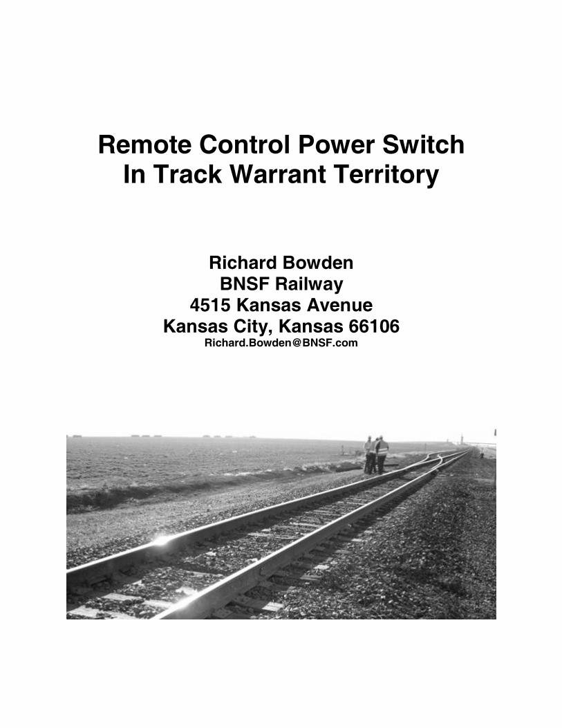
Remote Control Power Switch In Track Warrant Territory
Richard Bowden BNSF Railway
4515 Kansas Avenue Kansas City, Kansas 66106
ABSTRACT
Remote Control Power Switch in Track Warrant Territory
There is a need in the rail industry to provide remote control and remote monitoring of
main line switches in non-signaled track warrant control (TWC) territory. The ability to
remotely control and protect the movement of power switches has typically been to
install conventional Centralized Traffic Control (CTC). The installation costs of CTC can
be prohibitive to gain the operational benefits when the intent is only to control/monitor
the switch in TWC and not change the method of operations or speed of the track over
these switches. As a result, railroads have been reluctant to make this large capital
investment to achieve these operational benefits.
In a joint project with the Federal Railroad Administration (FRA), BNSF installed two
non-signaled remotely controlled power switch locations within track warrant control
territory in November, 2006. These locations provide the ability to remotely control non-
signaled main track switches from the BNSF train computer-aided dispatch (CAD)
system known as Train Management & Dispatch System (TMDS). The communications
medium to the Network Operation Center (NOC) uses authentication and data integrity
checks to increase security of switch movement requests and movement authority
requests to lock the switch. Logic in the vital programmable logic controller (US&S
Object Controller) allows the switch to be electrically locked to prevent the switch from
moving when there is a Track Warrant for train movement or the OS circuit is down.
When the switch is locked by an authority, it is mechanically and electronically locked
from moving.
This paper discusses the installation non-signaled remotely controlled power switches
within non-signaled track warrant control territory at Finney, TX, that uses much of the
conventional locking methodologies and conventional main track power switch
machines to achieve this objective.
KEY WORDS: FRA, RCPS, Warrant, Object Controller, SDR, M23
REMOTE CONTROL POWER SWITCH IN TRACK WARRANT TERRITORY
There is a need in the rail industry to provide remote control and remote monitoring of
main line switches in non-signaled track warrant control (TWC) territory. The ability to
remotely control and protect the movement of power switches has typically been to
install conventional Centralized Traffic Control (CTC). The installation costs of CTC can
be prohibitive to gain the operational benefits when the intent is only to control/monitor
the switch in TWC and not change the method of operations or speed of the track over
these switches. As a result, railroads have been reluctant to make this large capital
investment to achieve these operational benefits.
An operation and concept plan was developed to start implementation of a non-signaled
remote controlled power switch in non-signaled track warrant territory. The concept was
for the dispatcher to control the power switch directly through the Track Warrant system
(Figure 1). The track warrant system would be connected wirelessly to a wayside
controller which would retain much of the traditional CTC logic to control and lock the
switch.
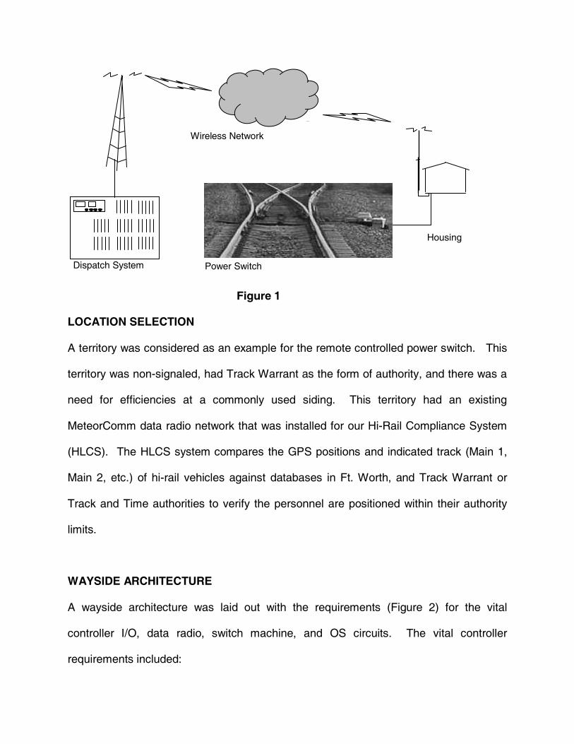
Figure 1
LOCATION SELECTION
A territory was considered as an example for the remote controlled power switch. This
territory was non-signaled, had Track Warrant as the form of authority, and there was a
need for efficiencies at a commonly used siding. This territory had an existing
MeteorComm data radio network that was installed for our Hi-Rail Compliance System
(HLCS). The HLCS system compares the GPS positions and indicated track (Main 1,
Main 2, etc.) of hi-rail vehicles against databases in Ft. Worth, and Track Warrant or
Track and Time authorities to verify the personnel are positioned within their authority
limits.
WAYSIDE ARCHITECTURE
A wayside architecture was laid out with the requirements (Figure 2) for the vital
controller I/O, data radio, switch machine, and OS circuits. The vital controller
requirements included:
Dispatch System
Wireless Network
Housing
Power Switch
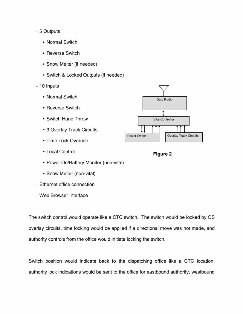
� 5 Outputs
� Normal Switch
� Reverse Switch
� Snow Melter (if needed)
� Switch & Locked Outputs (if needed)
� 10 Inputs
� Normal Switch
� Reverse Switch
� Switch Hand Throw
� 3 Overlay Track Circuits
� Time Lock Override
� Local Control
� Power On/Battery Monitor (non-vital)
� Snow Melter (non-vital)
� Ethernet office connection
� Web Browser Interface
The switch control would operate like a CTC switch. The switch would be locked by OS
overlay circuits, time locking would be applied if a directional move was not made, and
authority controls from the office would initiate locking the switch.
Switch position would indicate back to the dispatching office like a CTC location,
authority lock indications would be sent to the office for eastbound authority, westbound
Overlay Track Circuits Power Switch
Vital Controller
Data Radio
Figure 2
authority, and work between authority, expected train move complete indications would
be sent to the office when a train directionally shunts the OS circuits, and 8 minute time
locking would be evoked where train movement had not been completed, did not match
the authority control, or the authority was a work between. The wayside application
software would use CTC logic with the exception of Track Warrant authority replacing
signal controls and indications.
In addition to the above indications individual track overlay indications, power off, low
battery, manual operate and switch heater would be implemented.
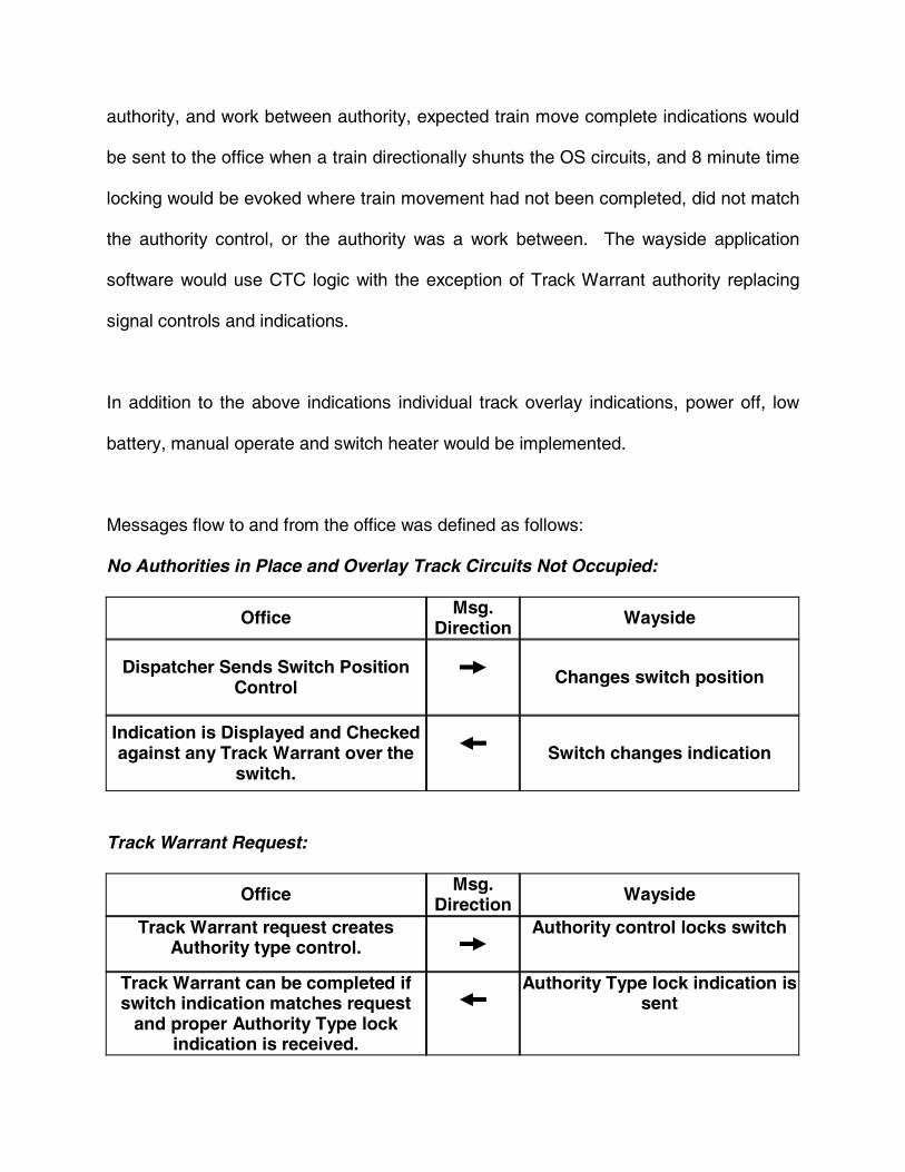
Messages flow to and from the office was defined as follows:
No Authorities in Place and Overlay Track Circuits Not Occupied:
Office Msg. Direction Wayside
Dispatcher Sends Switch Position Control
Changes switch position
Indication is Displayed and Checked against any Track Warrant over the
switch. Switch changes indication
Track Warrant Request:
Office Msg. Direction Wayside
Track Warrant request creates Authority type control.
Authority control locks switch
Track Warrant can be completed if switch indication matches request
and proper Authority Type lock indication is received.
Authority Type lock indication is sent
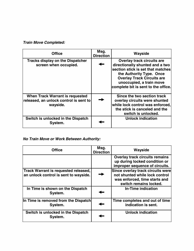
Train Move Completed:
Office Msg. Direction Wayside
Tracks display on the Dispatcher screen when occupied.
Overlay track circuits are directionally shunted and a two section stick is set that matches
the Authority Type. Once Overlay Track Circuits are unoccupied, a train move
complete bit is sent to the office.
When Track Warrant is requested released, an unlock control is sent to
wayside.
Since the two section track overlay circuits were shunted
while lock control was enforced, the stick is canceled and the
switch is unlocked. Switch is unlocked in the Dispatch
System.
Unlock indication
No Train Move or Work Between Authority:
Office Msg. Direction Wayside
Overlay track circuits remains up during locked condition or improper sequence of circuits.
Track Warrant is requested released, an unlock control is sent to wayside.
Since overlay track circuits were not shunted while lock control was enforced, time starts and
switch remains locked. In Time is shown on the Dispatch
System.
In-Time indication
In Time is removed from the Dispatch System.
Time completes and out of time indication is sent.
Switch is unlocked in the Dispatch System.
Unlock indication
FUNDING
The Federal Railroad Administration (FRA) had announced that funds were available for
demonstration projects and technology advancements. They specifically were looking
for projects that demonstrated cost reductions in constructing and maintaining track and
facilities, more efficient operations, improved reliability, improved safety, among other
criteria. Submittals were made to the FRA and after clarifying scope, costs, and
timeline, the FRA participated in funding and oversight of this development project.
WAYSIDE EQUIPMENT
For this project BNSF selected the US&S Object Controller for protocol, size, cost, and
Ethernet capability. US&S�s Peer Protocol was used between the office and the
wayside vital Object Controller. This protocol gives the capability to handle latent,
duplicate, corrupt, and pacing of messages. Within the Peer Protocol, ATCS messages
were used to give addressing redundancy and message type handling capability. On
top of the Peer Protocol an HMAC (keyed-Hash Message Authentication Code - a type
of message authentication code (MAC) calculated using a cryptographic hash function
in combination with a secret key) was added. The HMAC is used to provide both data
integrity and authenticity of a message. With it you verify the correct unit sent the
message and are able to verify the bits in the message are exactly what were sent by
the wayside unit or office.
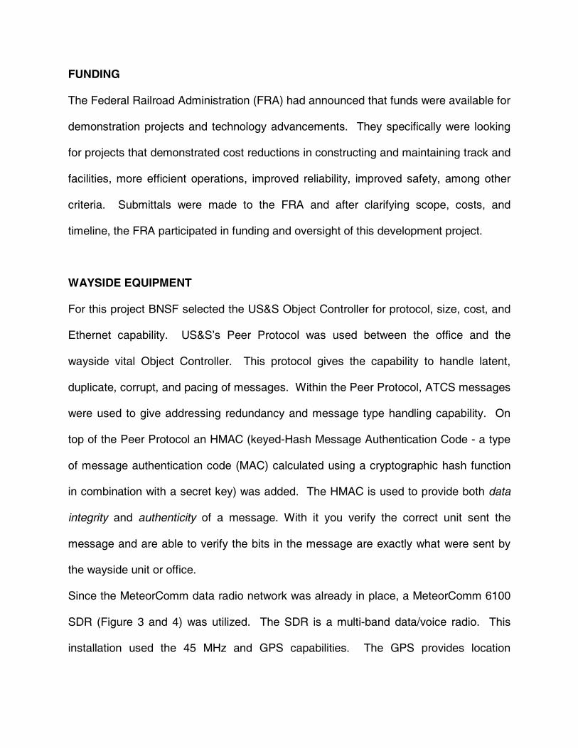
Since the MeteorComm data radio network was already in place, a MeteorComm 6100
SDR (Figure 3 and 4) was utilized. The SDR is a multi-band data/voice radio. This
installation used the 45 MHz and GPS capabilities. The GPS provides location
information and time to the unit. The 45 MHz band is used for data to the office. The
unit includes USB, Ethernet, serial, and miscellaneous I/O capabilities. The SDR
utilizes an external CIM module to backup the data radio application program.
The MeteorComm antenna installation
(Figure 5) is simple since it does not
require an external structure for
installation.
The SDR (Figure 6) was wall mounted
along with the DC-DC converter.
Figure 3
Figure 4
Figure 6
Figure 5
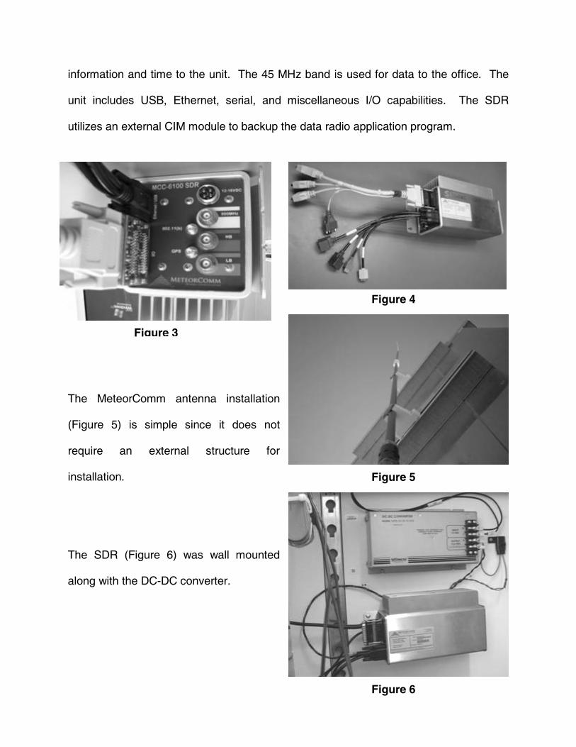
The connection to the Object Controller (Figure 7) is through a rolled (twisted) Ethernet
cable since there is not a hub between the data radio and the Object Controller. The
Object Controller�s Web Tool and local control panel (LCP) Ethernet ports are
connected through a hub to a laptop PC for programming and LCP capability.
The Object Controller (Figure 8) used has 12 inputs and 12 outputs and three Ethernet
ports. Health, port status, and user assigned LEDs are provided along with input and
output status LEDs.
Figure 7
Figure 8
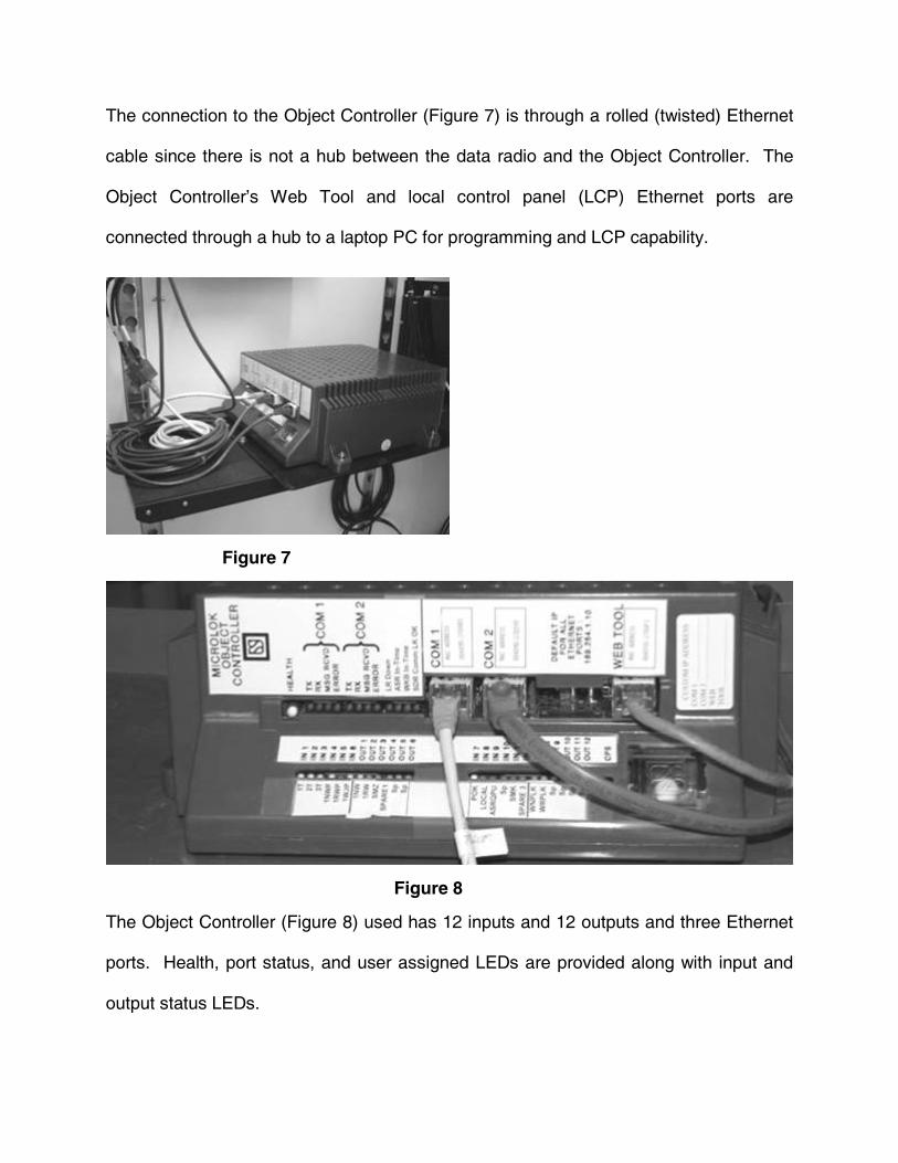
The Ethernet connected laptop PC
(Figure 9) provides programming access
to the Object Controller Web Tools and
LCP capability.
To access the Object Controller�s Web
port (Figure 10), set the laptop�s IP
address, type in the address of the Object
Controller and login. The Microlok Upload
button gives the ability to upload
application and Ethernet port software,
reboot the unit or Ethernet ports, and
display various settings.
The Network Diagnostic Tool (Figure 11)
displays executive and application
software versions along with the
application program name. This interface
also allows you to display board, link,
variable, and configuration information.
User data and event logs are also
available through this web interface.
Figure 9
Figure 10
Figure 11
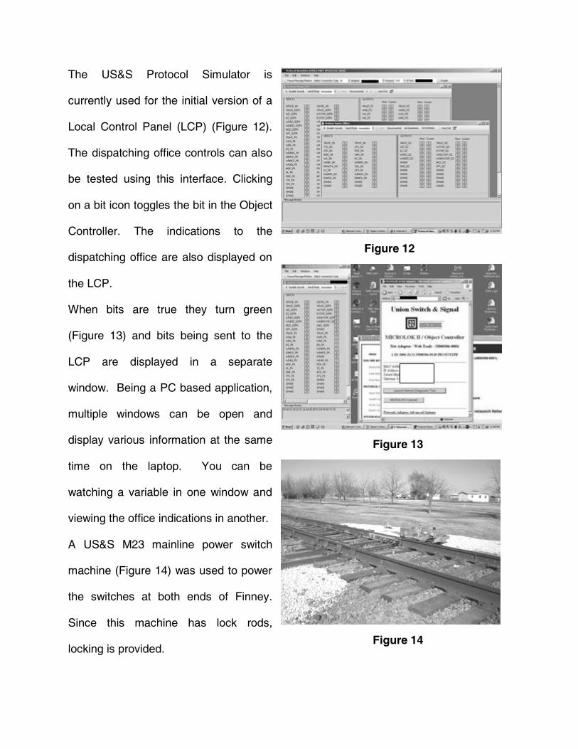
The US&S Protocol Simulator is
currently used for the initial version of a
Local Control Panel (LCP) (Figure 12).
The dispatching office controls can also
be tested using this interface. Clicking
on a bit icon toggles the bit in the Object
Controller. The indications to the
dispatching office are also displayed on
the LCP.
When bits are true they turn green
(Figure 13) and bits being sent to the
LCP are displayed in a separate
window. Being a PC based application,
multiple windows can be open and
display various information at the same
time on the laptop. You can be
watching a variable in one window and
viewing the office indications in another.
A US&S M23 mainline power switch
machine (Figure 14) was used to power
the switches at both ends of Finney.
Since this machine has lock rods,
locking is provided.
Figure 12
Figure 13
Figure 14
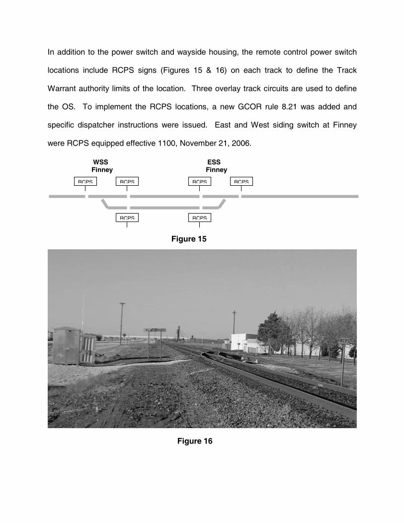
In addition to the power switch and wayside housing, the remote control power switch
locations include RCPS signs (Figures 15 & 16) on each track to define the Track
Warrant authority limits of the location. Three overlay track circuits are used to define
the OS. To implement the RCPS locations, a new GCOR rule 8.21 was added and
specific dispatcher instructions were issued. East and West siding switch at Finney
were RCPS equipped effective 1100, November 21, 2006.
ESS Finney
WSS Finney
RCPS RCPS
RCPS
RCPS RCPS
RCPS
Figure 15
Figure 16
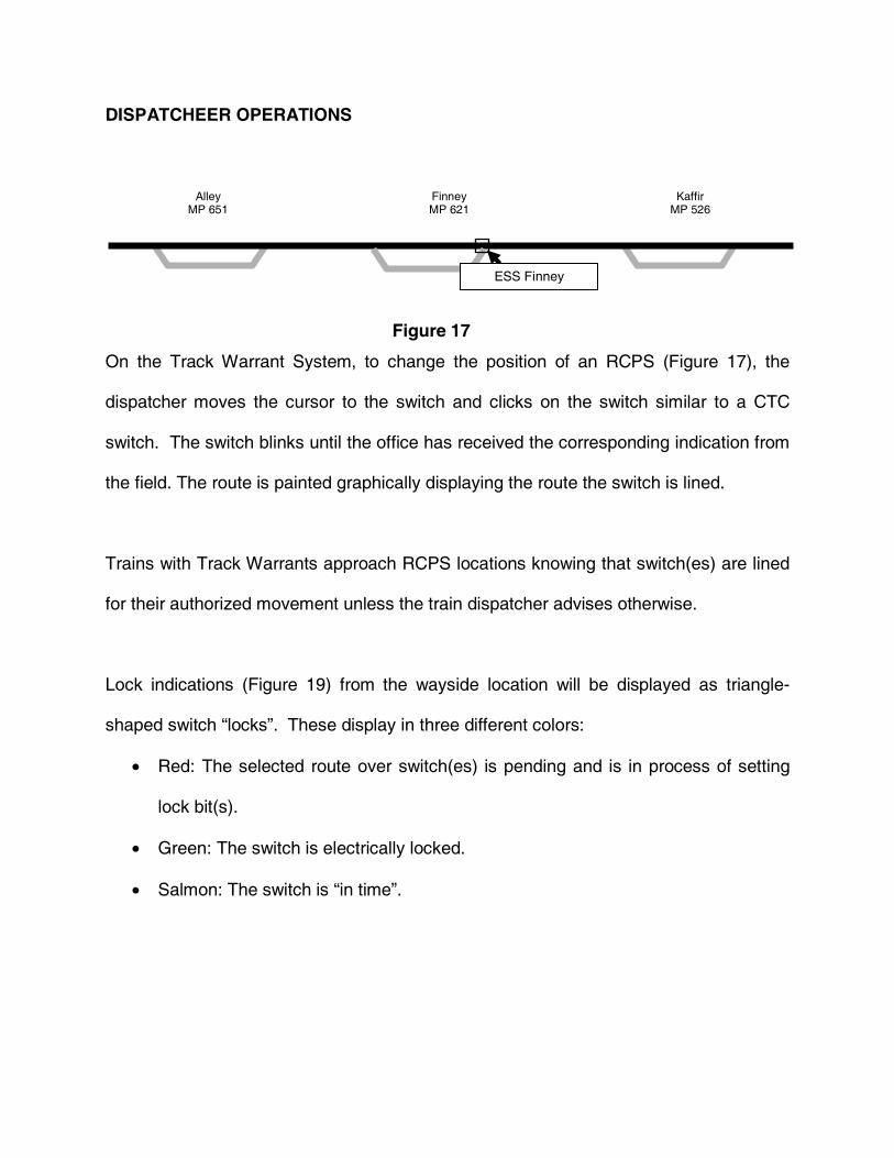
DISPATCHEER OPERATIONS
On the Track Warrant System, to change the position of an RCPS (Figure 17), the
dispatcher moves the cursor to the switch and clicks on the switch similar to a CTC
switch. The switch blinks until the office has received the corresponding indication from
the field. The route is painted graphically displaying the route the switch is lined.
Trains with Track Warrants approach RCPS locations knowing that switch(es) are lined
for their authorized movement unless the train dispatcher advises otherwise.
Lock indications (Figure 19) from the wayside location will be displayed as triangle-
shaped switch �locks�. These display in three different colors:
• Red: The selected route over switch(es) is pending and is in process of setting
lock bit(s).
• Green: The switch is electrically locked.
• Salmon: The switch is �in time�.
Alley MP 651
Finney MP 621
Kaffir MP 526
ESS Finney
Figure 17
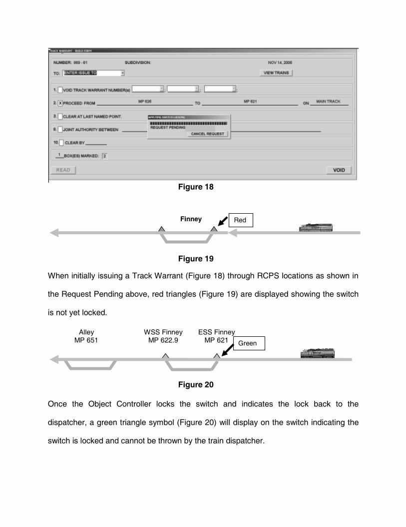
When initially issuing a Track Warrant (Figure 18) through RCPS locations as shown in
the Request Pending above, red triangles (Figure 19) are displayed showing the switch
is not yet locked.
Once the Object Controller locks the switch and indicates the lock back to the
dispatcher, a green triangle symbol (Figure 20) will display on the switch indicating the
switch is locked and cannot be thrown by the train dispatcher.
Finney Red
Alley MP 651
ESS Finney MP 621
WSS Finney MP 622.9 Green
Figure 18
Figure 19
Figure 20
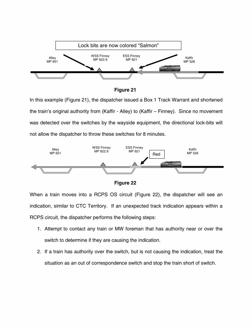
In this example (Figure 21), the dispatcher issued a Box 1 Track Warrant and shortened
the train�s original authority from (Kaffir - Alley) to (Kaffir � Finney). Since no movement
was detected over the switches by the wayside equipment, the directional lock-bits will
not allow the dispatcher to throw these switches for 8 minutes.
When a train moves into a RCPS OS circuit (Figure 22), the dispatcher will see an
indication, similar to CTC Territory. If an unexpected track indication appears within a
RCPS circuit, the dispatcher performs the following steps:
1. Attempt to contact any train or MW foreman that has authority near or over the
switch to determine if they are causing the indication.
2. If a train has authority over the switch, but is not causing the indication, treat the
situation as an out of correspondence switch and stop the train short of switch.
Alley MP 651
Kaffir MP 526
Lock bits are now colored �Salmon�
ESS Finney MP 621
WSS Finney MP 622.9
Alley MP 651
Kaffir MP 526
ESS Finney MP 621
WSS Finney MP 622.9
Red
Figure 21
Figure 22
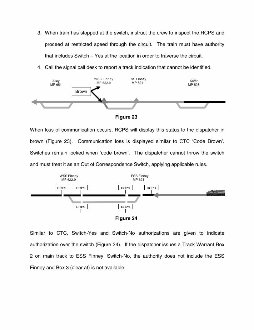
3. When train has stopped at the switch, instruct the crew to inspect the RCPS and
proceed at restricted speed through the circuit. The train must have authority
that includes Switch � Yes at the location in order to traverse the circuit.
4. Call the signal call desk to report a track indication that cannot be identified.
When loss of communication occurs, RCPS will display this status to the dispatcher in
brown (Figure 23). Communication loss is displayed similar to CTC �Code Brown�.
Switches remain locked when �code brown�. The dispatcher cannot throw the switch
and must treat it as an Out of Correspondence Switch, applying applicable rules.
Similar to CTC, Switch-Yes and Switch-No authorizations are given to indicate
authorization over the switch (Figure 24). If the dispatcher issues a Track Warrant Box
2 on main track to ESS Finney, Switch-No, the authority does not include the ESS
Finney and Box 3 (clear at) is not available.
Alley MP 651
Kaffir MP 526
ESS Finney MP 621
WSS Finney MP 622.9
Brown
WSS Finney MP 622.9
RCPS RCPS
RCPS
ESS Finney MP 621
RCPS RCPS
RCPS
Figure 23
Figure 24

If the dispatcher issues a Track Warrant Box 2 on main track to ESS Finney, Switch-
Yes (Figure 25). The authority does include the ESS Finney and Box 3 (clear at) is
available.
If an authority such as: �Box 2, Proceed from ESS Kaffir to WSS Alley on main track.� is
given and the switch which is locked, indicates out of correspondence (Figure 26), the
switch will flash. An alarm message will appear at the bottom of the dispatcher screen
(Figure 27). This alarm is required to be addressed before proceeding to other items.
WSS Finney MP 622.9
RCPS RCPS
RCPS
ESS Finney MP 621
RCPS RCPS
RCPS
Alley MP
Finney MP
Kaffir MP
Figure 25
Figure 26
Figure 27
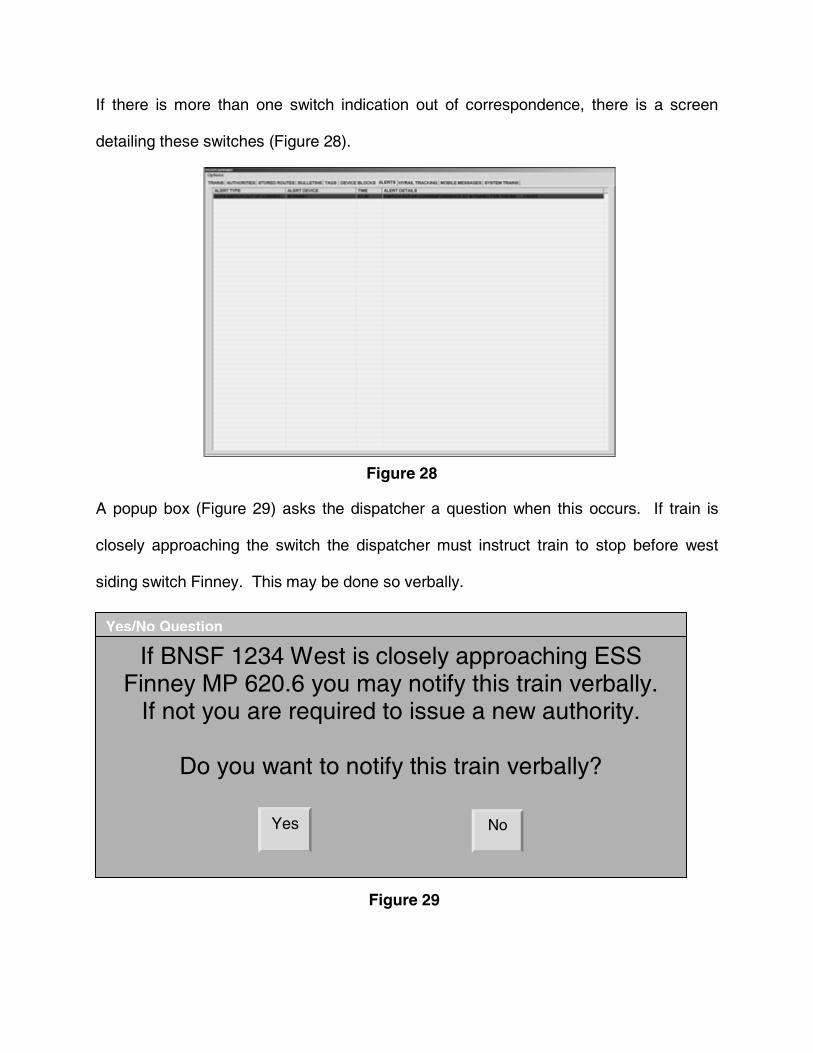
If there is more than one switch indication out of correspondence, there is a screen
detailing these switches (Figure 28).
A popup box (Figure 29) asks the dispatcher a question when this occurs. If train is
closely approaching the switch the dispatcher must instruct train to stop before west
siding switch Finney. This may be done so verbally.
Yes/No Question
If BNSF 1234 West is closely approaching ESS Finney MP 620.6 you may notify this train verbally.
If not you are required to issue a new authority.
Do you want to notify this train verbally?
Yes
No
Figure 28
Figure 29
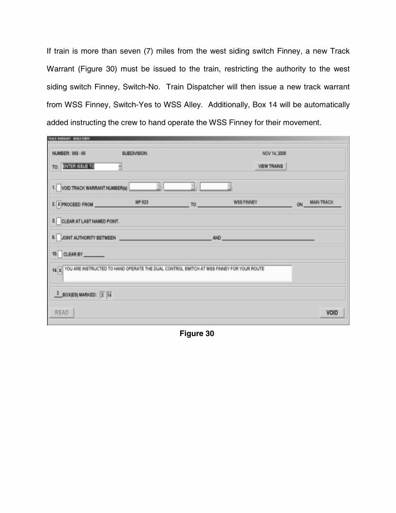
If train is more than seven (7) miles from the west siding switch Finney, a new Track
Warrant (Figure 30) must be issued to the train, restricting the authority to the west
siding switch Finney, Switch-No. Train Dispatcher will then issue a new track warrant
from WSS Finney, Switch-Yes to WSS Alley. Additionally, Box 14 will be automatically
added instructing the crew to hand operate the WSS Finney for their movement.
Figure 30
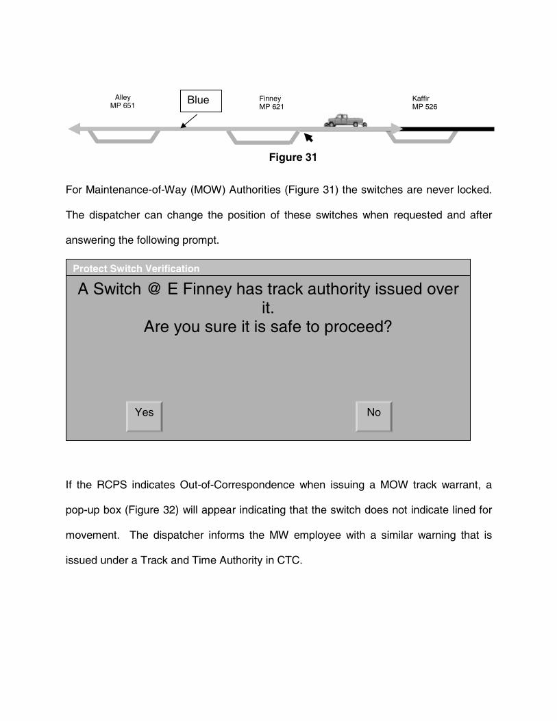
For Maintenance-of-Way (MOW) Authorities (Figure 31) the switches are never locked.
The dispatcher can change the position of these switches when requested and after
answering the following prompt.
If the RCPS indicates Out-of-Correspondence when issuing a MOW track warrant, a
pop-up box (Figure 32) will appear indicating that the switch does not indicate lined for
movement. The dispatcher informs the MW employee with a similar warning that is
issued under a Track and Time Authority in CTC.
Alley MP 651
Finney MP 621
Kaffir MP 526
Protect Switch Verification
A Switch @ E Finney has track authority issued over it.
Are you sure it is safe to proceed?
Yes No
Figure 31
Blue
CONCLUSIONS
Did we meet the original goals? These are just some of the criteria that met our
expectations:
1. Compared to installation of CTC to provide a power switch, there were cost
reductions in constructing and maintaining track and facilities due to:
� Fewer locations required
� Fewer track insulated joints required
� Fewer changes to existing crossing warning systems (none in this
case)
� Lower installation costs
2. More efficient operations were provided by:
� Switches positioned for meets
� Switches lined behind trains
3. Reliability was improved by:
� Direct indication to Dispatcher of current switch position
4. Safety was improved by:
� Switches are positioned for trains before authority is given.
� Dispatcher is notified of an out-of-correspondence switch.
� Crews don�t have to stop their train, disembark, hand line switches,
climb back on their train, and continue their movement.
� Switch point is monitored to ¼�.
� Lock rod backup is provided for the throw rod.

BNSF is currently working on follow up paperwork and documentation for the FRA on
this project. As a result of this joint project, RCPS is being integrated with ETMS on an
end of siding on our Beardstown Subdivision in Illinois and two other locations are in
progress on the Avard Subdivision in Oklahoma.
ACKNOWLEDGEMENTS
For any project there are a number of participants, BNSF construction and maintenance
personnel, signal engineering, and Mike Bratcher�s Ft. Worth Network Operations
Center group were just one team that made this happen. In addition, the following
agency and businesses supported the effort with countless hours of support and
creativity:
The Federal Railroad Administration (FRA) provided partial funding for this project.
The FRA also supported the project through review, comment, and field testing.
Union Switch & Signal supplied the containerized wayside material including the wired
housing, object controller, and switch machine. US&S also modified their peer protocol
to incorporate HMAC and developed PC Web browser interfaces. They also provided
personnel to test the office protocol and also provided excellent field support.
Meteor Communications modified the data radio and server software to support the
application, protocol and HMAC. They also provided personnel to test the protocol and
support the data radio network.
Wabtec supported the dispatching office implementation of switch control, HMAC, and
controls and indications for the remote control power switch. They also provided
personnel to test the protocol.
FIGURES
Figure 1 RCPS Concept
Figure 2 Wayside Architecture
Figure 3 MCC-6100 DSR Radio
Figure 4 MCC-6100 DSR Radio
Figure 5 Meteor Communication Antenna
Figure 6 MCC-6100 DSR Radio and DC/DC Converter
Figure 7 US&S Object Controller
Figure 8 US&S Object Controller
Figure 9 Laptop PC
Figure 10 US&S Object Controller Network Adapter
Figure 11 Network Diagnostic Tool
Figure 12 US&S Protocol Simulator
Figure 13 Multiple PC Applications
Figure 14 US&S M23 Switch Machine
Figure 15 RCPS Signs
Figure 16 West Finney
Figure 17 Changing Switch Position
Figure 18 Issuing Track Warrant
Figure 19 Lock Request Pending
Figure 20 Switch Locked
Figure 21 Switch in Time
Figure 22 Track Occupancy
Figure 23 Loss of Communication
Figure 24 �Switch No� in Authority
Figure 25 �Switch Yes� in Authority
Figure 26 Switch Out-of-Correspondence with Authority
Figure 27 Dispatcher Screen with Alarm
Figure 28 Switch List Screen
Figure 29 Popup Question for Out-of-Correspondence Switch
Figure 30 Revised Track Warrant
Figure 31 Maintenance of Way Authority
Figure 32 Popup Question for Throwing Switch with MOW Authority
REFERENCES
1. Website, http://www.fra.dot.gov, Federal Railroad Administration
2. Website, http://www.switch.com, Union Switch & Signal Incorporated
3. Website, http://www.meteorcomm.com, Meteor Communications Corporation
4. Website, http://www.wabtec.com, Wabtec Corporation
5. Website, http://www.bnsf.com, BNSF Railway