remote control extender - fcc id · introduction your wireless infrared extender kit consists of a...
TRANSCRIPT
Remote Control Extender
AUDIO / VIDEO DEVICES EXTENDING SYSTEM
MODEL NO.: AWX 701-A/AWX 701-B/AWX 701-C
OPERATION MANUAL

Remote Control Extender
AUDIO / VIDEO DEVICES EXTENDING SYSTEM
MODEL NO.: AWX 701-A/AWX 701-B/AWX 701-C
OPERATION MANUAL
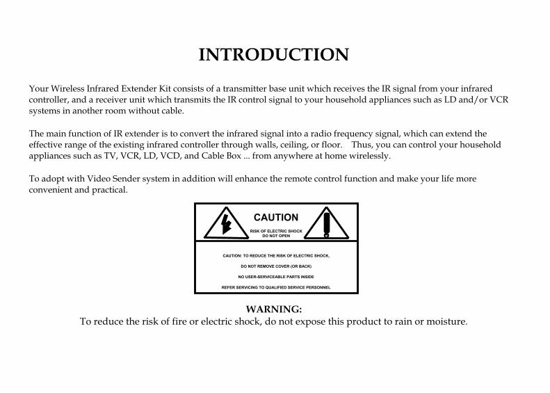
INTRODUCTION
Your Wireless Infrared Extender Kit consists of a transmitter base unit which receives the IR signal from your infrared
controller, and a receiver unit which transmits the IR control signal to your household appliances such as LD and/or VCR
systems in another room without cable.
The main function of IR extender is to convert the infrared signal into a radio frequency signal, which can extend the
effective range of the existing infrared controller through walls, ceiling, or floor. Thus, you can control your household
appliances such as TV, VCR, LD, VCD, and Cable Box ... from anywhere at home wirelessly.
To adopt with Video Sender system in addition will enhance the remote control function and make your life more
convenient and practical.
WARNING:
To reduce the risk of fire or electric shock, do not expose this product to rain or moisture.
CAUTION
RISK OF ELECTRIC SHOCK
DO NOT OPEN
CAUTION: TO REDUCE THE RISK OF ELECTRIC SHOCK,
DO NOT REMOVE COVER (OR BACK)
NO USER-SERVICEABLE PARTS INSIDE
REFER SERVICING TO QUALIFIED SERVICE PERSONNEL

SAFETY INSTRUCTIONS
1. Read Instructions - All the safety and operating instructions should be read before the product is operated.
2. Retain Instructions - The safety and operating instructions should be kept for future reference.
3. Heed Warnings - All warnings on the product and in the operating instructions should be adhered to.
4. Follow Instructions - All operating and use instructions should be followed.
5. Cleaning - Unplug this product from the wall outlet before cleaning. Do not use liquid cleaners or aerosol cleaners. Use
a damp cloth for cleaning.
6. Attachments - Do not use attachments not recommended by the product manufacturer as they may cause hazards.
7. Water and Moisture - Do not use this product near water - for example, near a bath tub, wash bowl, kitchen sink, or
laundry tub, in a wet basement, or near a swimming pool; and this like.
8. Accessories - Do not place this product on an unstable cart, stand, tripod, bracket, or table. The product may fall,
causing serious injury to a child or adult, and serious damage to the product. Use only with a cart, stand, tripod,
bracket, or table recommended by the manufacturer, or sold with the product. Any mounting of the product should
follow the manufacturer‘s instructions, and should use a mounting accessory recommended by the manufacturer.
9. A product and cart combination should be moved with care. Quick stops, excessive force and uneven surfaces may
cause the product and cart combination to overturn.
1
10. Ventilation - Slots and openings in the cabinet are provided for ventilation and to ensure reliable operation of the
product and to protect it from overheating, and these openings must be blocked or covered. The openings should
never be blocked by placing the product on a bed, sofa, rug, or other similar surface. This product should not be placed
in a built-in installation such as a bookcase or rack unless proper ventilation is provided or the manufacturer‘s
instructions have been adhered to.
11. Power Sources - This product should be operated only from the type of power source indicated on the marking label. If
you are not sure of the type or power supply to your home, consult your product dealer or local power company. For
products intended to operate from battery power, or other sources, refer to the operating instructions.
12. Power-Cord Protection - Power supply cords should be routed so that they are not likely to be walked on or pinched
by items placed upon or against them, paying particular attention to cords at plugs, convenience receptacles, and the
point where they exit from the product.
13. Lightning - For added protection for this product during a lightning storm, or when it s is left unattended and unused
for long periods of time, unplug it from the wall outlet and disconnect the antenna or cable system. This will prevent
damage to the product due to lightning and power-line surges.
14. Overloading - Do not overload wall outlets, extension cords, or integral convenience receptacles as this can result in a
risk of fire or electric shock.
15. Object and Liquid Entry - Never push objects of any kind into this product through openings as they may touch
dangerous voltage points or short-out parts that could result in a fire or electric shock. Never spill liquid of any kind on
the product.
16. Servicing - Do not attempt to service this product yourself as opening or removing covers may expose you to
dangerous voltage or other hazards. Refer all servicing to qualified service personnel.
2
17. Damage Requiring Service - Unplug this product from the wall outlet and refer servicing to qualified service personnel
under the following conditions:
18. When the power-supply cord or plug is damaged,
19. If liquid has been spilled, or objects have fallen into the product,
20. If the product has been exposed to rain or water,
21. If the product does not operate normally by following the operating instructions. Adjust only those controls that are
covered by the operating instructions as an improper adjustment of other controls may result in damage and will often
require extensive work by a qualified technician to restore the product to its normal operation,
22. If the product has been dropped or damaged in any way, and
23. When the product exhibits a distinct change in performance - this indicates a need for service.
24. Heat - The product should be situated away from heat sources such as radiators, hear registers, stoves, or other
products including amplifiers that produce heat.
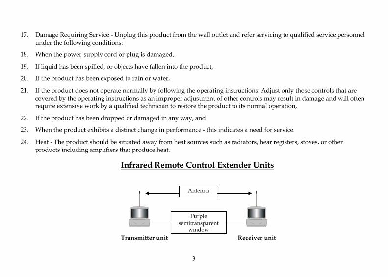
Infrared Remote Control Extender Units
Transmitter unit Receiver unit
Antenna
Purple
semitransparent
window
3

Installation of IR Extender:
1. Power Supply of IR Extender:
1.1. Transmitter unit:
The transmitter unit can operate by using a power adapter :
1.1.1. Using Power Adapter:
1.1.1.1. Plug the input port (AC 110/220V) of Power Adapter into an AC outlet.
1.1.1.2. Plug the output port (DC 12/9V) of Power Adapter into the input jack on the rear of the transmitter.
1.2. Receiver unit:
Must apply adapter for power supply only. Please refer to the above clause of item 1.2.
(AC outlet)(power adapter)
(DC input jack)
(back view of the transmitter)
(antenna)
(IR OUT)
option
4

2. Installation Process of IR Extender system:
2.1. Connect power supply for transmitter and receiver as per step in item A.
2.2. Insert the attached antenna into the socket on the top of the transmitter and receiver unit individually.
(The antenna is optional not for standard Accessories.)
2.3. Set up the receiver unit in front of your electronic appliances (TV, VCR, ...) to be remotely controlled and arrange
the unit so that its purple semitransparent window faces the electronic appliances.
2.4. Aim the infrared controller of your electronic appliance at the purple semitransparent windows of the transmitter
unit and operate the transmitter unit in the same way as aiming directly at the electronic appliance.
2.5. If the transmitter receives the infrared signal successfully, the purple semitransparent windows of transmitter
will flash the red LED light and transmit RF signal to the receiver.
2.6. If the IR receiver receives the RF signal successfully, its window will also flash the red LED light simultaneously
and emit IR signal to the household appliances (TV/VCR) and the remote control process is totally completed by
now.
3. Application Example:
Rx
Tx
IR LED
* Remote
Controlor Mouse IR LED
IR Sensor
5
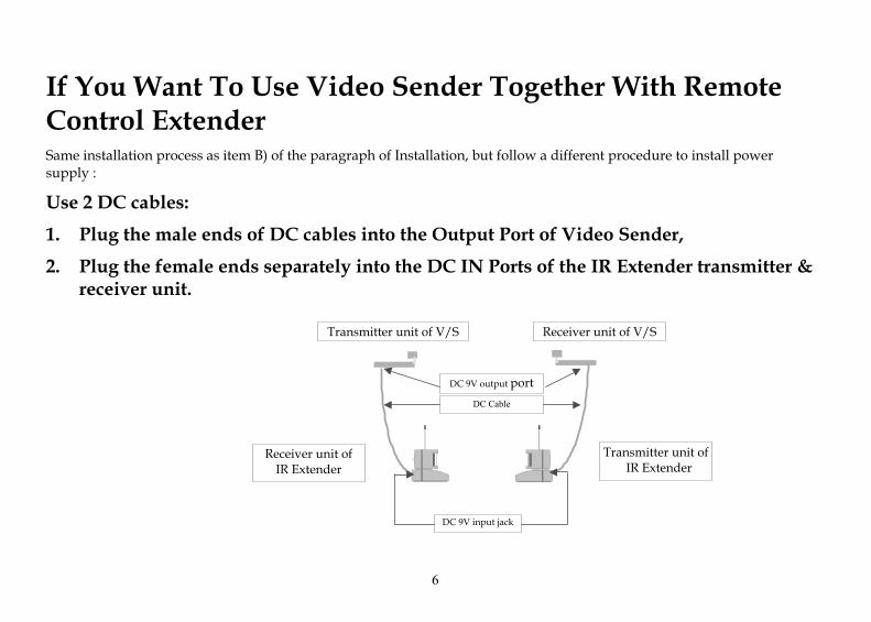
If You Want To Use Video Sender Together With Remote
Control Extender
Same installation process as item B) of the paragraph of Installation, but follow a different procedure to install power
supply :
Use 2 DC cables:
1. Plug the male ends of DC cables into the Output Port of Video Sender,
2. Plug the female ends separately into the DC IN Ports of the IR Extender transmitter &
receiver unit.
Transmitter unit of V/S Receiver unit of V/S
Receiver unit of
IR Extender
Transmitter unit of
IR Extender
DC 9V output port
DC Cable
DC 9V input jack
6
Trouble Shooting
1. Transmitter unit does not follow the commands from infrared controller
1.1. Check the power supply of transmitter first,
1.2. For batteries power only -
Check the batteries and be sure the “+, - ” ends are correct and double check if the batteries still work.
1.3. Check the distance between your infrared controller and the transmitter unit of IR Extender - its effective
transmitting range is within 10 meters.
2. If receiver unit does not work, but transmitter unit works with the commands from
infrared controller
2.1. Check the power supply of receiver first - normally when the power is on, the semitransparent window of
receiver will flash the read LED light once.
2.2. Check the antenna of the transmitter & receiver of IR extender- be sure they are firmly installed.
2.3. Check the distance between the transmitter & its receiver of IR Extender - normally the effective transmitting
range at line of sight is about 100 meters.
3. The transmitter & receiver units do work but cannot follow the right commands from
your infrared controller
3.1. Check the direction of transmitter semitransparent window of the receiver unit of IR Extender - be sure its
direction is to the household appliance to control,
7
3.2. Check the batteries power of the remote controller of your electronic appliance - be sure the batteries are still able
to work,
3.3. Check the distance between the receiver unit of IR Extender and your household appliance to control - the
distance can not be over 10 meters,
3.4. Confirm the RF frequency of 418 MHz transmitting between the transmitter unit of IR Extender and its receiver
units not being interfered - if someone else uses the same frequency for transmitting nearby (such as wireless
headphone), the signal will certainly get worse.
4. If you do follow the above mentioned process, double check your IR extender system
and the problem still exists, please call your product dealer for maintenance.
Warning:
• This device complies with Part 15 of the FCC Rules. Operation is subject to the
following two conditions: (1) this device may not cause harmful interference, and (2)
this device must accept any interference received, including interference that may
cause undesired operation.
Any changes or modifications not expressly approved by the party responsible for
compliance could void the authority to operate equipment.
8

DOC0000-0167

AWX701 SPECIFICATIONS
General
Operate frequency range 418±0.1MHz(USA) Power ON indicater LED(Red)
IR operating indicate LED(Red)
Antenna type dipole
IR RF Operating distance 30M Line sight Supply voltage DC 9V
Operation temperature 0℃-50℃ Indoor use only
Storage temperature -20℃-70℃
418MHz±100kHz 65mm×147mm×57mm Weight 50g
Transmitter Transmission measure level 82.33dBuV(Vertical)
Modulation type ASK IR frequency stability ±1MHz Infrared emission wavelength 940nm
IR Sensor Operation Range 7.5M (min) Standby current consumption 3±2mA Current consumption 12±5mA
Receiver IR RF receive senstivity -95±3dBm min IR carrier frequency 34KHz ±1.5KHz IR sensor half angle 45° Horizontals IR LED operation Range 3M(min) Standby current consumption 9±5mA Current consumption 16±5mA
AWX701 SPECIFICATIONS
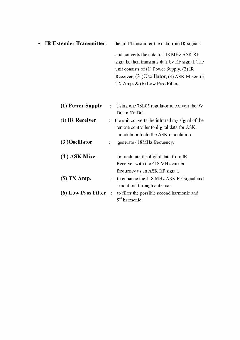
˙ IR Extender Transmitter: the unit Transmitter the data from IR signals
and converts the data to 418 MHz ASK RF signals, then transmits data by RF signal. The unit consists of (1) Power Supply, (2) IR Receiver, (3 )Oscillator, (4) ASK Mixer, (5) TX Amp. & (6) Low Pass Filter.
(1) Power Supply : Using one 78L05 regulator to convert the 9V DC to 5V DC.
(2) IR Receiver : the unit converts the infrared ray signal of the remote controller to digital data for ASK
modulator to do the ASK modulation. (3 )Oscillator : generate 418MHz frequency. (4 ) ASK Mixer : to modulate the digital data from IR
Receiver with the 418 MHz carrier frequency as an ASK RF signal.
(5) TX Amp. : to enhance the 418 MHz ASK RF signal and send it out through antenna.
(6) Low Pass Filter : to filter the possible second harmonic and 5rd harmonic.