remine d5.1 noemalife wp5 - european commission · contract no: 216134 d7.4 – remine 3rd pilot...
TRANSCRIPT
PROPRIETARY RIGHTS STATEMENT
This document contains information, which is proprietary to the REMINE Consortium. Neither this
document nor the information contained herein shall be used, duplicated or communicated by any
means to any third party, in whole or in parts, except with prior written consent of the REMINE
Consortium.
ReMINE
High performances prediction, detection and monitoring
platform for patient safety risk management
FP7 Contract: 216134
– Deliverable –
D7.4
ReMINE 3rd Pilot Platform

Contract No: 216134
D7.4 – ReMINE 3rd Pilot Platform
Revision: Final Security: Confidential (Consortium only)
Page 2/85
Document Information
Document Name: ReMINE_D7.4_NoemaLife_WP7_V0.11.doc Revision: Final Revision Date: 25/11/2011 Author: Cristiano Querzè (NoemaLife) Contributors: --------------------------------------------------------- Security: Confidential (Consortium Only)
Document Information
Consortium only
Approvals
Name Beneficiary Date Visa
Project Coordinator Michele CARENINI NOEMALIFE
Technical Manager Efstathia KORMARI ICCS
Document History
Revision Date Modification Author
Version 0.1 12/10/2011 ToC first draft NL
Version 0.2 13/10/2011 ToC Refinement and circulation to the consortium
ICCS
Version 0.3 26/10/2011 NoemaLife Contributions NL
Version 0.4 2/11/2011 added contributions LINK, TUW, IW
Version 0.5 2/11/2011 added contributions INDRA
Version 0.6 3/11/2011 added contributions ICCS
Version 0.7 8/11/2011 added contributions NL
Version 0.8 8/11/2011 added contributions and refinements
ICCS
Version 0.9 9/11/2011 refinements TUW
Version 0.10 10/11/2011 refinements
Version 0.11 11/11/2011 Executive Summary NL, ICCS
Final 25/11/2011 Contribution integration, overall check
NL, ICCS, INDRA

Contract No: 216134
D7.4 – ReMINE 3rd Pilot Platform
Revision: Final Security: Confidential (Consortium only)
Page 3/85
Table of contents
1. Executive summary ......................................................................................................................... 6 1.1. Project Overview ..................................................................................................................... 6 1.2. Task Description ...................................................................................................................... 6
2. Abbreviations .................................................................................................................................. 7 3. 2nd and 3rd Prototype components ............................................................................................. 10 4. Pilots Server Specifications ............................................................................................................ 13 5. H-ERP Bridge .................................................................................................................................. 14
5.1. Purpose .................................................................................................................................. 14 5.2. 2nd Prototype Functionalities................................................................................................. 14 5.3. 3rd Final Prototype Functionalities ........................................................................................ 15 5.4. Dependencies ........................................................................................................................ 15 5.5. Interfaces with other components ........................................................................................ 15 5.6. Resources .............................................................................................................................. 16 5.7. Data/Messages ...................................................................................................................... 16 5.7.1. Niguarda (IT) ...................................................................................................................... 16 5.7.1.1. Data ............................................................................................................................... 16 5.7.1.2. Messages ....................................................................................................................... 17 5.7.2. Sacco (IT) ........................................................................................................................... 18 5.7.2.1. Data ............................................................................................................................... 18 5.7.2.2. Messages ....................................................................................................................... 20 5.7.3. TRFT (UK) ........................................................................................................................... 21 5.7.3.1. Data ............................................................................................................................... 21 5.7.3.2. Messages ....................................................................................................................... 23 5.7.4. SEK (FIN) ............................................................................................................................ 24 5.7.4.1. Data ............................................................................................................................... 24 5.7.4.2. Messages ....................................................................................................................... 26 5.8. Installation instructions ......................................................................................................... 26
6. Data Acquisition Layer ................................................................................................................... 27 6.1. Purpose .................................................................................................................................. 27 6.2. 2nd Prototype Functionalities ............................................................................................... 27 6.3. 3rd Prototype Functionalities ................................................................................................ 27 6.4. Dependencies ........................................................................................................................ 28 6.5. Interfaces with other components ........................................................................................ 28 6.6. Resources .............................................................................................................................. 28 6.7. Data/Messages ...................................................................................................................... 28 6.8. Installation instructions ......................................................................................................... 33
7. Intalio Processes ............................................................................................................................ 33 7.1. Purpose .................................................................................................................................. 33 7.2. 2nd and 3rd Prototype Functionalities Comparison ............................................................. 34 7.3. Dependencies ........................................................................................................................ 34 7.4. Interfaces with other components ........................................................................................ 35 7.5. Resources .............................................................................................................................. 35 7.6. Data/Messages ...................................................................................................................... 35 7.7. Installation instructions ......................................................................................................... 36
8. ReMINE Database .......................................................................................................................... 37

Contract No: 216134
D7.4 – ReMINE 3rd Pilot Platform
Revision: Final Security: Confidential (Consortium only)
Page 4/85
8.1. Purpose .................................................................................................................................. 38 8.2. 2nd Prototype Functionalities ............................................................................................... 38 8.3. 3rd Prototype Functionalities ................................................................................................ 39 8.4. Dependencies ........................................................................................................................ 39 8.5. Interfaces with other components ........................................................................................ 39 8.6. Resources .............................................................................................................................. 39 8.7. Data/Messages ...................................................................................................................... 40 8.8. Installation instructions ......................................................................................................... 49
9. Data mining and Knowledge Extraction ........................................................................................ 56 9.1. Purpose .................................................................................................................................. 56 9.2. 2nd Prototype Implementation............................................................................................. 56 9.3. 3rd Prototype Implementation ............................................................................................. 56 9.4. Dependencies ........................................................................................................................ 57 9.5. Interfaces with other components ........................................................................................ 57 9.6. Resources .............................................................................................................................. 57 9.7. Data/Messages ...................................................................................................................... 57
10. Guideline Execution Engine ....................................................................................................... 59 10.1. Purpose .............................................................................................................................. 59 10.2. 2nd Prototype Functionalities ........................................................................................... 59 10.3. 3rd Prototype Functionalities ............................................................................................ 59 10.4. Dependencies .................................................................................................................... 59 10.5. Interfaces with other components .................................................................................... 59 10.6. Resources .......................................................................................................................... 59 10.7. Data/Messages .................................................................................................................. 60 10.8. Installation instructions ..................................................................................................... 60
11. Visualisation tool (Research Prototype Component -not integrated with ReMINE platform) . 60 11.1. Purpose .............................................................................................................................. 60 11.2. 2nd Prototype Functionalities ........................................................................................... 60 11.3. 3rd Prototype Functionalities ............................................................................................ 60 11.4. Dependencies .................................................................................................................... 60 11.5. Interfaces with other components .................................................................................... 61 11.6. Resources .......................................................................................................................... 61 11.7. Data/Messages .................................................................................................................. 61 11.8. Installation Instructions ..................................................................................................... 61
12. User Interface ........................................................................................................................... 62 12.1. Purpose .............................................................................................................................. 62 12.2. 2nd and 3rd Prototype Functionalities Comparison ......................................................... 63 12.3. Dependencies .................................................................................................................... 64 12.4. Interfaces with other components .................................................................................... 66 12.5. Resources .......................................................................................................................... 66 12.6. Data/Messages .................................................................................................................. 66 12.7. Installation instructions ..................................................................................................... 67
13. Alerting System ......................................................................................................................... 67 12.8. Purpose .............................................................................................................................. 67 13.2. 2nd Prototype Functionalities ........................................................................................... 68 13.3. 3rd Prototype Functionalities ............................................................................................ 68 13.4. Dependencies .................................................................................................................... 68
Contract No: 216134
D7.4 – ReMINE 3rd Pilot Platform
Revision: Final Security: Confidential (Consortium only)
Page 5/85
13.5. Interfaces with other components .................................................................................... 68 13.6. Resources .......................................................................................................................... 69 13.7. Data/Messages .................................................................................................................. 70 13.8. Installation instructions ..................................................................................................... 72
14. Rules Engine .............................................................................................................................. 75 14.1. Purpose .............................................................................................................................. 75 14.2. 2nd Prototype Functionalities ........................................................................................... 75 14.3. 3rd Prototype Functionalities ............................................................................................ 75 14.4. Dependencies .................................................................................................................... 76 14.5. Interfaces with other components .................................................................................... 76 14.6. Resources .......................................................................................................................... 76 14.7. Data/Messages .................................................................................................................. 77 14.8. Installation instructions ..................................................................................................... 77
15. DVD Structure ............................................................................................................................ 78 16. Annex ......................................................................................................................................... 79 16.1. SLA ......................................................................................................................................... 79 16.2. Pilots Remote Access (added the other 2 pilots SEK and TRFT) ............................................ 79 16.2.1. Niguarda Hospital .................................................................................................................. 79 16.2.2. Sacco Hospital ....................................................................................................................... 82 16.2.3. TRFT Hospital (UK) ................................................................................................................. 84 16.2.4. Kauhajoki Hospital (FIN) ........................................................................................................ 85
Contract No: 216134
D7.4 – ReMINE 3rd Pilot Platform
Revision: Final Security: Confidential (Consortium only)
Page 6/85
1. Executive summary
1.1. Project Overview
The present document constitutes a deliverable of the Work Package (WP) 7 –Demonstration, Task
7.2 - ‘System integration, testing and validation (DEM)’ of the REMINE FP7 EU co-funded R&D
project.
This deliverable describes in detail the final platform prototype. It is important to notice that, as
agreed upon by the reviewers and the Commission during ATR2, the first and second prototypes
were merged in a single prototype, so in this deliverable are described all the components of the final
ReMINE platform (3rd prototype) and a comparison between the 1&2nd Prototype with the 3rd.
Moreover is described all the additional work implemented from the last ATR.
The final platform has received a number of improvements and now includes all the functionalities
originally foreseen.
NoemaLife, the deliverable responsible, has coordinated the analysis of the platform described in this
deliverable; all the technical partners involved in task T7.2 activities and, in general, in WP7 activities
have participated and contributed to the completion of the deliverable.
1.2. Task Description
The objective of the task is to define and develop the “Running PILOTs Site ” REMINE Platform, integrated with the all components and deployed in the PILOTS site, that will be called the “REMINE Production Prototype (RPP)”. The Deliverable D7.4 takes in account the ReMINE Final Platform (RFP) describing the last developments and modifications passing from RPP2 to RFP.
Contract No: 216134
D7.4 – ReMINE 3rd Pilot Platform
Revision: Final Security: Confidential (Consortium only)
Page 7/85
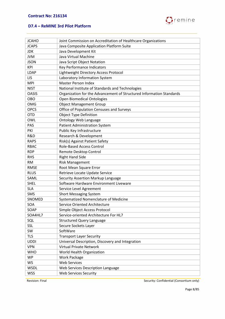
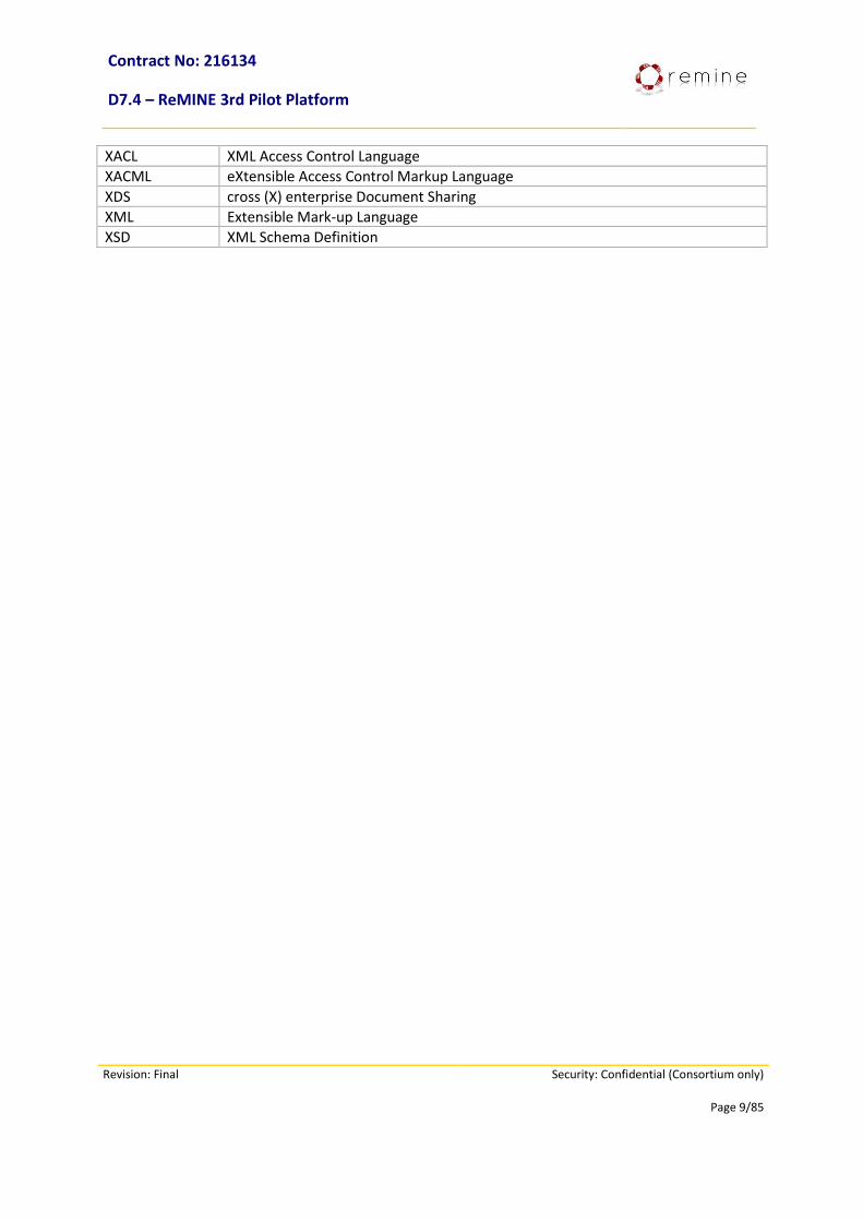
2. Abbreviations Abbreviation Stands for
A&E Accident & Emergency
ACM Association of Computing Machinery
AE Adverse Event
API Application Programming Interface
ATNA Audit Trail and Node Authentication
B2B Business-to-Business
BAM Business Activity Monitoring
BFO Basic Formal Ontology
BPEL Business Process Execution Language
BPM Business Process Management
BPMI Business Process Management Initiative
BPMN Business Process Modeling Notation
BRE Business Rule Engine
CA Certification Authority
CDA Clinical Document Architecture
CEN Committee Européen de Normalisation
CIA Confidentiality, Integrity, Authentication
CTS Common Terminology Service
DAL Data Acquisition Layer
DB DataBase
DBMS DataBase Management System
DEMS Data Events Management System
DOLCE Descriptive Ontology for Linguistic and Cognitive Engineering
DRL Drools Rule Language
DSL Domain Specific Languages
EHR Electronic Health Record
EIS Entity Identification Service
ERP Enterprise Resource Planning
ESB Enterprise Service Bus
ETL Extract Transform Load
EU European Union
GUI Graphical User Interface
H-ERP Hospital Enterprise Resource Planning
HIS Hospital Information System
HL7 Health Level 7
HSSP Healthcare Services Specification Project
HTML Hyper Text Markup Language
HTTPS Hyper Text Protocol Secure
HW HardWare
ICD International Classification of Diseases and related health problems
IHE Integrating the Healthcare Enterprise
ISO International Organization for Standardization
Contract No: 216134
D7.4 – ReMINE 3rd Pilot Platform
Revision: Final Security: Confidential (Consortium only)
Page 8/85
JCAHO Joint Commission on Accreditation of Healthcare Organizations
JCAPS Java Composite Application Platform Suite
JDK Java Development Kit
JVM Java Virtual Machine
JSON Java Script Object Notation
KPI Key Performance Indicators
LDAP Lightweight Directory Access Protocol
LIS Laboratory Information System
MPI Master Person Index
NIST National Institute of Standards and Technologies
OASIS Organization for the Advancement of Structured Information Standards
OBO Open Biomedical Ontologies
OMG Object Management Group
OPCS Office of Population Censuses and Surveys
OTD Object Type Definition
OWL Ontology Web Language
PAS Patient Administration System
PKI Public Key Infrastructure
R&D Research & Development
RAPS Risk(s) Against Patient Safety
RBAC Role-Based Access Control
RDP Remote Desktop Control
RHS Right Hand Side
RM Risk Management
RMSE Root Mean Square Error
RLUS Retrieve Locate Update Service
SAML Security Assertion Markup Language
SHEL Software Hardware Environment Liveware
SLA Service Level Agreement
SMS Short Messaging System
SNOMED Systematized Nomenclature of Medicine
SOA Service Oriented Architecture
SOAP Simple Object Access Protocol
SOA4HL7 Service-oriented Architecture For HL7
SQL Structured Query Language
SSL Secure Sockets Layer
SW SoftWare
TLS Transport Layer Security
UDDI Universal Description, Discovery and Integration
VPN Virtual Private Network
WHO World Health Organization
WP Work Package
WS Web Services
WSDL Web Services Description Language
WSS Web Services Security
Contract No: 216134
D7.4 – ReMINE 3rd Pilot Platform
Revision: Final Security: Confidential (Consortium only)
Page 9/85
XACL XML Access Control Language
XACML eXtensible Access Control Markup Language
XDS cross (X) enterprise Document Sharing
XML Extensible Mark-up Language
XSD XML Schema Definition
Contract: 216134
D7.4 – ReMINE 3rd Pilot Platform
Revision: V0.11 Security: Confidential (Consortium only)
Page 10/85
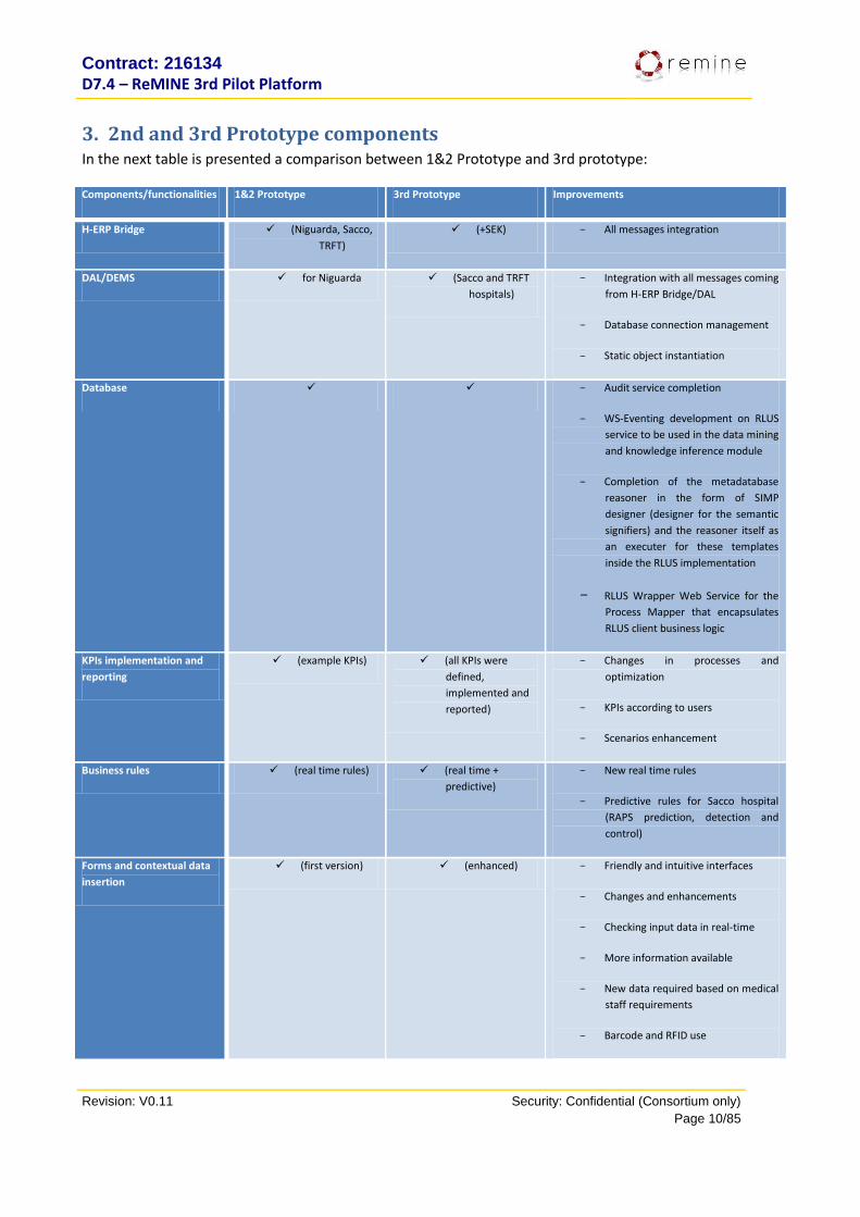
3. 2nd and 3rd Prototype components In the next table is presented a comparison between 1&2 Prototype and 3rd prototype:
Components/functionalities 1&2 Prototype 3rd Prototype Improvements
H-ERP Bridge (Niguarda, Sacco,
TRFT)
(+SEK) - All messages integration
DAL/DEMS for Niguarda (Sacco and TRFT
hospitals)
- Integration with all messages coming
from H-ERP Bridge/DAL
- Database connection management
- Static object instantiation
Database - Audit service completion
- WS-Eventing development on RLUS
service to be used in the data mining
and knowledge inference module
- Completion of the metadatabase
reasoner in the form of SIMP
designer (designer for the semantic
signifiers) and the reasoner itself as
an executer for these templates
inside the RLUS implementation
- RLUS Wrapper Web Service for the
Process Mapper that encapsulates
RLUS client business logic
KPIs implementation and
reporting
(example KPIs) (all KPIs were
defined,
implemented and
reported)
- Changes in processes and
optimization
- KPIs according to users
- Scenarios enhancement
Business rules (real time rules) (real time +
predictive)
- New real time rules
- Predictive rules for Sacco hospital
(RAPS prediction, detection and
control)
Forms and contextual data
insertion
(first version) (enhanced) - Friendly and intuitive interfaces
- Changes and enhancements
- Checking input data in real-time
- More information available
- New data required based on medical
staff requirements
- Barcode and RFID use
Contract: 216134
D7.4 – ReMINE 3rd Pilot Platform
Revision: V0.12 Draft Security: Confidential (Consortium only)
Page 11/85
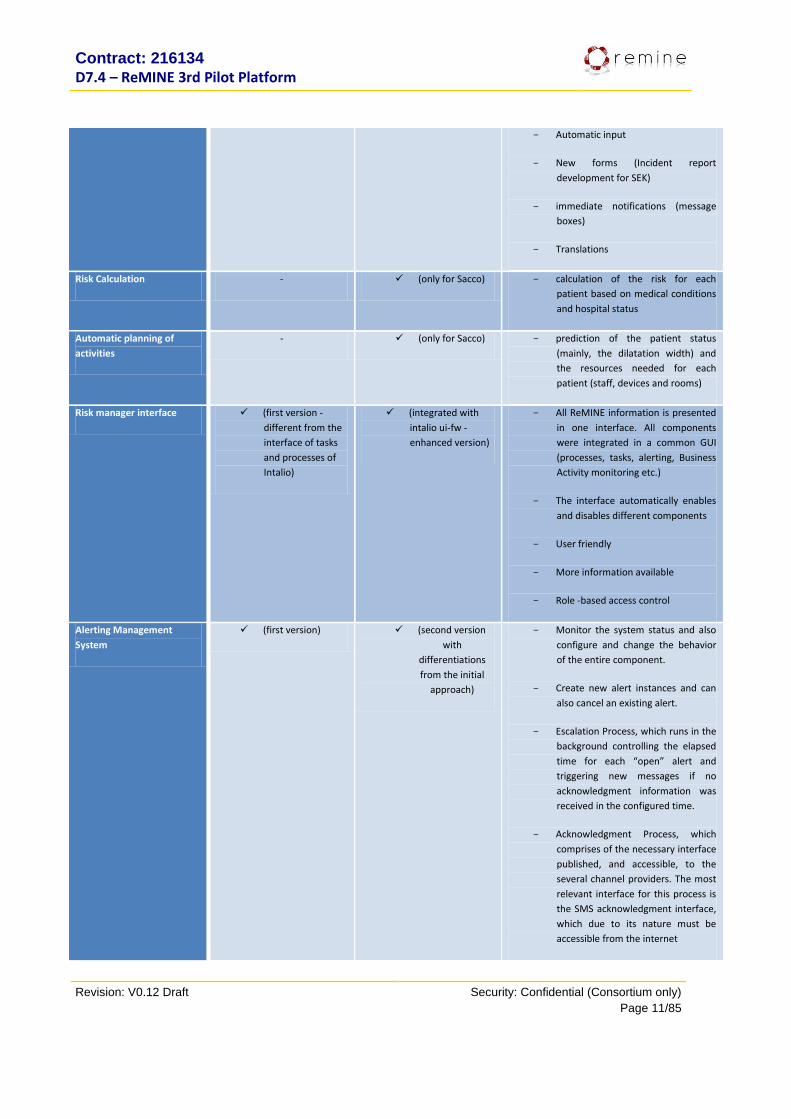
- Automatic input
- New forms (Incident report
development for SEK)
- immediate notifications (message
boxes)
- Translations
Risk Calculation - (only for Sacco) - calculation of the risk for each
patient based on medical conditions
and hospital status
Automatic planning of
activities
- (only for Sacco) - prediction of the patient status
(mainly, the dilatation width) and
the resources needed for each
patient (staff, devices and rooms)
Risk manager interface (first version -
different from the
interface of tasks
and processes of
Intalio)
(integrated with
intalio ui-fw -
enhanced version)
- All ReMINE information is presented
in one interface. All components
were integrated in a common GUI
(processes, tasks, alerting, Business
Activity monitoring etc.)
- The interface automatically enables
and disables different components
- User friendly
- More information available
- Role -based access control
Alerting Management
System
(first version) (second version
with
differentiations
from the initial
approach)
- Monitor the system status and also
configure and change the behavior
of the entire component.
- Create new alert instances and can
also cancel an existing alert.
- Escalation Process, which runs in the
background controlling the elapsed
time for each “open” alert and
triggering new messages if no
acknowledgment information was
received in the configured time.
- Acknowledgment Process, which
comprises of the necessary interface
published, and accessible, to the
several channel providers. The most
relevant interface for this process is
the SMS acknowledgment interface,
which due to its nature must be
accessible from the internet
Contract: 216134
D7.4 – ReMINE 3rd Pilot Platform
Revision: V0.12 Draft Security: Confidential (Consortium only)
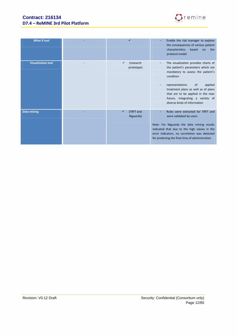
Page 12/85
What if tool - - Enable the risk manager to explore
the consequences of various patient
characteristics based on the
protocol model
Visualization tool - (research
prototype)
- The visualization provides charts of
the patient’s parameters which are
mandatory to assess the patient’s
condition
- representations of applied
treatment plans as well as of plans
that are to be applied in the near
future, integrating a variety of
diverse kinds of information
Data mining - (TRFT and
Niguarda)
- Rules were extracted for TRFT and
were validated by users
Note: For Niguarda the data mining results
indicated that due to the high values in the
error indicators, no correlation was detected
for predicting the final time of administration

Contract: 216134
D7.4 – ReMINE 3rd Pilot Platform
Revision: V0.12 Draft Security: Confidential (Consortium only)
Page 13/85
4. Pilots Server Specifications This section will describe in brief the specifications in terms of HW and SW associated with the REMINE
pilots. The set-up prescribed here is common for all 4 of the REMINE pilots. Since a precise setup cannot be
achieved due to the nature of the different OEM suppliers and hardware manufacturers, small deviations
are permitted as long as the changes are checked with the integration leader (Q&R).
The following Hardware specifications apply to the REMINE Pilots’ Server:
Hardware
Processors Type Intel: Xeon E7450
Multi-Core processor technology: 6-core
64-bit processor: Yes
Processor Qty: 1
Processor number: E7450
Clock speed: 2.4 GHz
Cache Memory Installed Size L2 cache – 3x3=9 MB
Installed Size L3 cache - 12 MB
RAM 8 GB
Storing capacity At least 500 GB usable (redundancy level: at least Raid 1 or 5)
It is strongly suggested that the Server is constructed in such a way so as to allow for future expansion
capabilities in terms of CPU, RAM and storing capacity.
Contract: 216134
D7.4 – ReMINE 3rd Pilot Platform
Revision: V0.12 Draft Security: Confidential (Consortium only)
Page 14/85
5. H-ERP Bridge This section provides information regarding the ‘H-ERP Bridge’ Module which is responsible for
gathering data from Hospital Information Systems, in order to make them available via HL7/XML schemas
to the ‘Data Acquisition Layer’ and subsequently the ‘Data Event Management System’, responsible for
coding, tagging and ‘classifying’ this data based on the REMINE ontology rules and the ‘Data Events’
definitions established, while also for thereafter storing them into the REMINE Database.
5.1. Purpose The ‘H-ERP Bridge’ (‘H-ERP’ in following) inputs data directly from the HIS’s of the Pilots, including such
information as patient historical data, test results, etc, through a number of dedicated/customised
interfaces. This module is also responsible for the communication with ‘Data Acquisition Layer’ (DAL)
module via a messaging and queuing system.
5.2. 2nd Prototype Functionalities As previous described the H-ERP bridge is responsible for gathering information from HISs and send
them to DAL module in standard way (HL7/XML V2.5) via a dedicated set of customised interfaces
specifically deployed for the Pilot’s HISs, developed and running on a specific integration middleware
In the second prototype H-ERP bridge developed the whole engine and the main integration adapters for IT
pilots (Niguarda and Sacco).
To address effectively this particular requirement in the most ‘generic’ fashion, the H-ERP has been
designed to be capable of handling data from hospital data sources in two different ways as follows:
Data Mart PUSH: Connection with these data sources must be maintain at all times by the H-ERP in order to:
o Retrieve all data coming from those sources. o Select data of interest. o Queue data into a dedicated message queue. o Transform them for the ‘Data Acquisition Layer’ (HL7/XML Protocol Transformation). o ‘Push’ them to the ‘Data Acquisition Layer’.
Data Mart PULL: These sources must be available for ‘querying’ at any time by the H-ERP in order to:
o Retrieve the results of specific queries posed by the DAL on the data marts agreed. o Perform data queries to the HIS. o Retrieve queried data from the HIS. o Select data of interest. o Queue them into a dedicated message queue. o Transform them for the ‘Data Acquisition Layer’ (HL7/XML Protocol Transformation). o Push them to the ‘Data Acquisition Layer’.
Contract: 216134
D7.4 – ReMINE 3rd Pilot Platform
Revision: V0.12 Draft Security: Confidential (Consortium only)
Page 15/85
The two different ways are used in the pilots as described in the following:
Push WebService exposed by Data Acquisition Layer and used by H-ERP Bridge for the “pushing” integration of the HL7 messages. This way is used for pushing messages from the HIS of Niguarda, Sacco and TRFT (3 Push scenarios).
Pull WebService exposed by the H-ERP Bridge and used by the Data Acquisition Layer for retrieving (“pulling”) the available type of messages. This way is also used in SEK Hospital for getting clinical information from SEK HIS using Effica (The name of SEK HIS) Web Services. Then H-ERP bridge process the clinical information gathered from HIS and convert them in standard HL7 messages sent via HL7 in push way to DAL.
5.3. 3rd Final Prototype Functionalities For the Final Prototype of the H-ERP Bridge module, the main enhancements are related to the following
items:
- NIGUARDA Pilot (IT)
o Consolidation of the integrations developed for 1st and 2nd prototype.
o Bug fixing.
- SACCO Pilot (IT)
o Consolidation of the integrations developed for 1st and 2nd prototype.
o Bug fixing.
- TRFT Pilot (UK)
o Development, test and Go Live of all the integrations required
- SEK Pilot (FIN)
o Development, test and Go Live of all the integrations required
5.4. Dependencies For its role, the H-ERP depends in particular from two main actors:
1) The Pilot’s HIS’s interface with 3rd parties
2) The DAL module:
5.5. Interfaces with other components As described before for its role, the H-ERP is directly linked with to two main actors:
3) The Pilot’s HIS: H-ERP depends directly on the associated SW platforms deployed for performing
the ‘role’ of the local Hospital Information System. For the 4 pilots involved in the project H-ERP has
been developed in order to manage 4 different type of HIS with 4 different types of integration
Adapter:
a. NIG: HL7 V2.5 Piped to HL7 V2.5 XML integration adapter
Contract: 216134
D7.4 – ReMINE 3rd Pilot Platform
Revision: V0.12 Draft Security: Confidential (Consortium only)
Page 16/85
b. SACCO: DB materialized Views to HL7V2.5 XML integration adapter
c. TRFT: HL7 V2.4 Piped to HL7 V2.5 XML integration adapter
d. SEK: Web Services to HL7V2.5 XML integration adapter
4) The DAL module: H-ERP is directly connected to the DAL module for 2 activities:
a. Sending data via HL7 version 2.5 and XML.
b. Receiving specific queries via Web services in order to retrieve specific associated clinical or
other data (for SEK Scenario)
5.6. Resources The H-ERP module places the following two specific resources requirements on the REMINE platform:
The Enterprise Service Bus JCAPS (Java Composite Application Platform Suite (ORACLE-SUN)) application to standardize and manage all data integrations between Clinical SW platforms.
A physical Server (HW and O.S.) in order to host the JCAPS application and the Runtime of the integration adapters.
5.7. Data/Messages
5.7.1. Niguarda (IT)
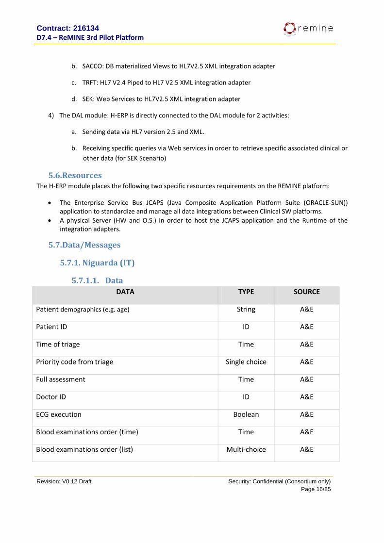
5.7.1.1. Data
DATA TYPE SOURCE
Patient demographics (e.g. age) String A&E
Patient ID ID A&E
Time of triage Time A&E
Priority code from triage Single choice A&E
Full assessment Time A&E
Doctor ID ID A&E
ECG execution Boolean A&E
Blood examinations order (time) Time A&E
Blood examinations order (list) Multi-choice A&E
Contract: 216134
D7.4 – ReMINE 3rd Pilot Platform
Revision: V0.12 Draft Security: Confidential (Consortium only)
Page 17/85
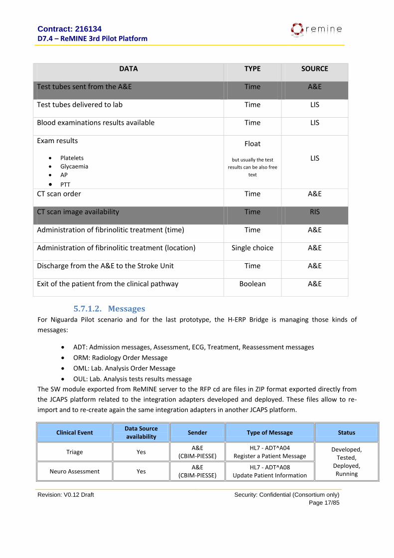
DATA TYPE SOURCE
Test tubes sent from the A&E Time A&E
Test tubes delivered to lab Time LIS
Blood examinations results available Time LIS
Exam results
Platelets
Glycaemia
AP
PTT
Float
but usually the test
results can be also free
text
LIS
CT scan order Time A&E
CT scan image availability Time RIS
Administration of fibrinolitic treatment (time) Time A&E
Administration of fibrinolitic treatment (location) Single choice A&E
Discharge from the A&E to the Stroke Unit Time A&E
Exit of the patient from the clinical pathway Boolean A&E
5.7.1.2. Messages For Niguarda Pilot scenario and for the last prototype, the H-ERP Bridge is managing those kinds of
messages:
ADT: Admission messages, Assessment, ECG, Treatment, Reassessment messages
ORM: Radiology Order Message
OML: Lab. Analysis Order Message
OUL: Lab. Analysis tests results message
The SW module exported from ReMINE server to the RFP cd are files in ZIP format exported directly from
the JCAPS platform related to the integration adapters developed and deployed. These files allow to re-
import and to re-create again the same integration adapters in another JCAPS platform.
Clinical Event Data Source availability
Sender Type of Message Status
Triage Yes A&E
(CBIM-PIESSE) HL7 - ADT^A04
Register a Patient Message Developed,
Tested, Deployed, Running Neuro Assessment Yes
A&E (CBIM-PIESSE)
HL7 - ADT^A08 Update Patient Information

Contract: 216134
D7.4 – ReMINE 3rd Pilot Platform
Revision: V0.12 Draft Security: Confidential (Consortium only)
Page 18/85
Lab tests Order Yes A&E
(CBIM-PIESSE)
HL7 - OML^O33 Laboratory Order for Multiple
Orders Related to a Single Specimen Message
Lab samples CheckIN Yes LIS
(NoemaLife-DNLab)
HL7 - OML^O21 Laboratory Order
Lab tests Results Yes LIS
(NoemaLife-DNLab)
HL7 - OUL_R22 Unsolicited Specimen Oriented
Observation Message
Radiology tests Order (Head CT Scan)
Yes A&E
(CBIM-PIESSE) HL7 - ORM-O01 General Order
Image Ready from Radiology dept.
NO RIS
(Agfa - Elefante) NA NA
ECG Execution Yes A&E
(CBIM-PIESSE)
HL7 - ADT^A08 Update Patient Information
Message
Developed, Tested,
Deployed, Running
Fibrinolitic Treatment Yes A&E
(CBIM-PIESSE)
HL7 - ADT^A08 Update Patient Information
Message
A&E ReAssesment Yes A&E
(CBIM-PIESSE)
HL7 - ADT^A08 Update Patient Information
Message
A&E Exit from Clinical Pathway
Yes A&E
(CBIM-PIESSE)
HL7 - ADT^A08 Update Patient Information
Message
A&E Discharge Yes A&E
(CBIM-PIESSE) HL7 - ADT^A03
Discharge/End Visit Message
5.7.2. Sacco (IT)
5.7.2.1. Data DATA TYPE SOURCE
Admission A&E
Patient demographics (e.g. age) String ISOLA BELLA
Patient ID ID ISOLA BELLA
Time of triage Time ISOLA BELLA
Active labour diagnosis check list Form
Nulliparous vs. Parous Single choice

Contract: 216134
D7.4 – ReMINE 3rd Pilot Platform
Revision: V0.12 Draft Security: Confidential (Consortium only)
Page 19/85
DATA TYPE SOURCE
Contractions ≥ 2 in 10 minutes, regular and painful? Boolean
Cervical length %
Low risk labour diagnosis check list Form
Physiological medical and obstetric history Boolean
Singleton healthy gestation in vertex position Boolean
Absence of known fetal disease Boolean
37-41+6 completed weeks of gestational age confirmed by
ultrasound
Boolean
Intact membranes or rupture of the membranes < 24 hours
with clear amniotic fluid and negative vaginal tampon
Boolean
Estimate of fetal weight between 2500 and 4000 grams Boolean
Normally inserted placenta Boolean
Spontaneous labour Boolean
FHR monitoring registration Form/Barcode
Start of monitoring Time
End of monitoring Time
Patient name String
Patient ID ID
Midwife name String
Midwife ID ID
Device ID String
Obstetrician assessment monitoring Form
Contract: 216134
D7.4 – ReMINE 3rd Pilot Platform
Revision: V0.12 Draft Security: Confidential (Consortium only)
Page 20/85
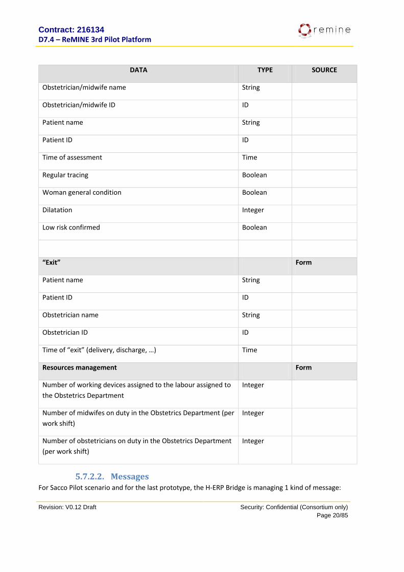
DATA TYPE SOURCE
Obstetrician/midwife name String
Obstetrician/midwife ID ID
Patient name String
Patient ID ID
Time of assessment Time
Regular tracing Boolean
Woman general condition Boolean
Dilatation Integer
Low risk confirmed Boolean
“Exit” Form
Patient name String
Patient ID ID
Obstetrician name String
Obstetrician ID ID
Time of “exit” (delivery, discharge, …) Time
Resources management Form
Number of working devices assigned to the labour assigned to
the Obstetrics Department
Integer
Number of midwifes on duty in the Obstetrics Department (per
work shift)
Integer
Number of obstetricians on duty in the Obstetrics Department
(per work shift)
Integer
5.7.2.2. Messages For Sacco Pilot scenario and for the last prototype, the H-ERP Bridge is managing 1 kind of message:

Contract: 216134
D7.4 – ReMINE 3rd Pilot Platform
Revision: V0.12 Draft Security: Confidential (Consortium only)
Page 21/85
ADT: Admission messages
The SW module exported from ReMINE server to the RFP cd are files in ZIP format exported directly from the JCAPS platform related to the integration adapters developed and deployed. These files allow to re-import and to re-create again the same integration adapters in another JCAPS platform.
Clinical Event Data
Source availability
Sender Type of Message Status
Patient Admission Yes A&E
(Praezision-Isolabella) HL7 - ADT^A04
Register a Patient Message
Developed, Tested,
Deployed, Running
5.7.3. TRFT (UK)
5.7.3.1. Data
DATA TYPE SOURCE
Use Case 1
Patient name String PAS/Form
Patient address String PAS
Previous MRSA infections Boolean PAS
Previous C. diff. flag Boolean PAS
Previous ESBL flag Boolean PAS
Patient infection code Single choice Form
Patient actual ward String PAS
Patient previous wards String PAS
Last MRSA test date Date LIS
Last MRSA test results String LIS
Last C. diff. test date Date LIS
Last C. diff. test results String LIS
Last ESBL test date Date LIS

Contract: 216134
D7.4 – ReMINE 3rd Pilot Platform
Revision: V0.12 Draft Security: Confidential (Consortium only)
Page 22/85
DATA TYPE SOURCE
Last ESBL test results String LIS
Use Case 2
Cubicle ID String Form
Patient name String Form
Patient infection code Single choice Form
Cubicle status Single choice Form
Kind of cleaning Single choice Form
Assigned staff String Form
Completed cleaning Time Form
Use Case 3
Patient name String LIS/Form
Patient infection code Single choice Form
Kind of infection String Form
MRSA screening order Date & Time LIS
MRSA screening results String LIS
Use Case 4
Patient name String PAS/Form
Patient infection code Single choice Form
Patient actual ward String PAS
Patient previous wards String PAS

Contract: 216134
D7.4 – ReMINE 3rd Pilot Platform
Revision: V0.12 Draft Security: Confidential (Consortium only)
Page 23/85
DATA TYPE SOURCE
Ward admittance Date PAS
Ward discharge Date PAS
5.7.3.2. Messages For TRFT Pilot scenario and for the last prototype, the H-ERP Bridge is managing 2 kind of messages:
ADT: Admission and Patient messages
ORU: Lab. Analysis tests results message
The SW module exported from ReMINE server to the RFP cd are files in ZIP format exported directly from
the JCAPS platform related to the integration adapters developed and deployed. These files allow to re-
import and to re-create again the same integration adapters in another JCAPS platform.
Clinical Event Data
Source availability
Sender Type of Message Status
Patient Admission Yes PAS
(Totalcare) HL7 - ADT^A01
Admit/Visit notification message
Developed, Tested,
Deployed, Running
Patient Update Yes PAS
(Totalcare) HL7 - ADT^A08
Update Patient Information message
Lab. Tests Results Yes LIS
(WinPath) HL7 - ORU^R01
Unsolicited Observation message
Patient Transfer Yes PAS
(Totalcare) HL7 - ADT^A02
Transfer Patient Message
Patient Discharge Yes PAS
(Totalcare) HL7 - ADT^A03
Discharge/End Visit message
Patient Registration Yes PAS
(Totalcare) HL7 - ADT^A28
Patient Registration
Patient Details Update Yes PAS
(Totalcare) HL7 - ADT^A31 Patient Update
Patient Merge Yes PAS
(Totalcare) HL7 - ADT^A34 Patient Merge
Change Patient ID Yes PAS
(Totalcare) HL7 - ADT^A47
Change Patient ID
Contract: 216134
D7.4 – ReMINE 3rd Pilot Platform
Revision: V0.12 Draft Security: Confidential (Consortium only)
Page 24/85
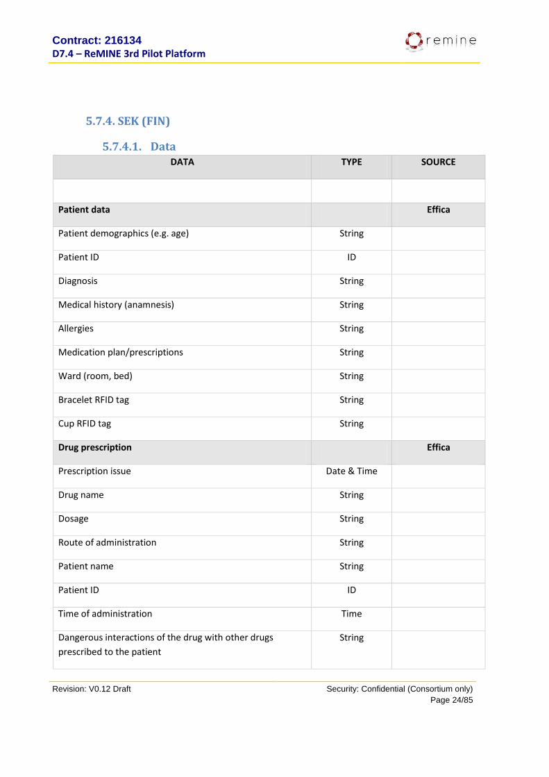
5.7.4. SEK (FIN)
5.7.4.1. Data DATA TYPE SOURCE
Patient data Effica
Patient demographics (e.g. age) String
Patient ID ID
Diagnosis String
Medical history (anamnesis) String
Allergies String
Medication plan/prescriptions String
Ward (room, bed) String
Bracelet RFID tag String
Cup RFID tag String
Drug prescription Effica
Prescription issue Date & Time
Drug name String
Dosage String
Route of administration String
Patient name String
Patient ID ID
Time of administration Time
Dangerous interactions of the drug with other drugs
prescribed to the patient
String
Contract: 216134
D7.4 – ReMINE 3rd Pilot Platform
Revision: V0.12 Draft Security: Confidential (Consortium only)
Page 25/85
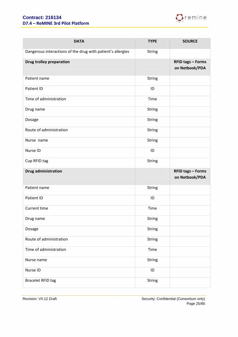
DATA TYPE SOURCE
Dangerous interactions of the drug with patient’s allergies String
Drug trolley preparation RFID tags – Forms
on Netbook/PDA
Patient name String
Patient ID ID
Time of administration Time
Drug name String
Dosage String
Route of administration String
Nurse name String
Nurse ID ID
Cup RFID tag String
Drug administration RFID tags – Forms
on Netbook/PDA
Patient name String
Patient ID ID
Current time Time
Drug name String
Dosage String
Route of administration String
Time of administration Time
Nurse name String
Nurse ID ID
Bracelet RFID tag String
Contract: 216134
D7.4 – ReMINE 3rd Pilot Platform
Revision: V0.12 Draft Security: Confidential (Consortium only)
Page 26/85
DATA TYPE SOURCE
Cup RFID tag String
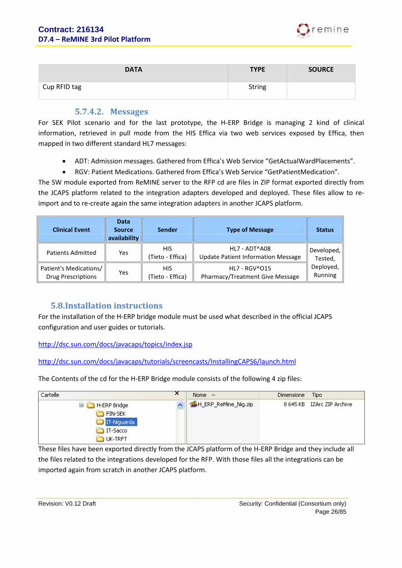
5.7.4.2. Messages For SEK Pilot scenario and for the last prototype, the H-ERP Bridge is managing 2 kind of clinical
information, retrieved in pull mode from the HIS Effica via two web services exposed by Effica, then
mapped in two different standard HL7 messages:
ADT: Admission messages. Gathered from Effica’s Web Service “GetActualWardPlacements”.
RGV: Patient Medications. Gathered from Effica’s Web Service “GetPatientMedication”.
The SW module exported from ReMINE server to the RFP cd are files in ZIP format exported directly from
the JCAPS platform related to the integration adapters developed and deployed. These files allow to re-
import and to re-create again the same integration adapters in another JCAPS platform.
Clinical Event Data
Source availability
Sender Type of Message Status
Patients Admitted Yes HIS
(Tieto - Effica) HL7 - ADT^A08
Update Patient Information Message Developed,
Tested, Deployed, Running
Patient's Medications/ Drug Prescriptions
Yes HIS
(Tieto - Effica) HL7 - RGV^O15
Pharmacy/Treatment Give Message
5.8. Installation instructions For the installation of the H-ERP bridge module must be used what described in the official JCAPS
configuration and user guides or tutorials.
http://dsc.sun.com/docs/javacaps/topics/index.jsp
http://dsc.sun.com/docs/javacaps/tutorials/screencasts/InstallingCAPS6/launch.html
The Contents of the cd for the H-ERP Bridge module consists of the following 4 zip files:
These files have been exported directly from the JCAPS platform of the H-ERP Bridge and they include all
the files related to the integrations developed for the RFP. With those files all the integrations can be
imported again from scratch in another JCAPS platform.
Contract: 216134
D7.4 – ReMINE 3rd Pilot Platform
Revision: V0.12 Draft Security: Confidential (Consortium only)
Page 27/85
6. Data Acquisition Layer
6.1. Purpose This component is responsible for processing the largely varied data received from the Hospital information
System (HIS), before storing them as part of the REMINE DB. This processing mainly includes the
transformation of the hospital ‘messages’ passed on by the ‘H-ERP Bridge’ component from their HL7 XML
form into the CDA/non-CDA used by the REMINE DB. Moreover, this layer will also ‘enrich’ the associated
data with appropriate ‘coding’ references (i.e. SNOMED, LOINC, ICD9/10).
The DAL component consists one of the core ReMINE components where a semantic transformation of the
data coming from pilots HIS, is taking place for further usage by the ReMINE platform.
6.2. 2nd Prototype Functionalities The functionality of the component is described as follows:
Receive/collect, parse and transform a new HL7 v2.x message from ‘H-ERP Bridge’ component.
There are two different ways that this functionality is offered. The first and simpler way is a “PUSH”
scenario where the H-ERP bridge pushes the HL7 v2.x messages through a web service exposed by
the DAL component. The second way is a “PULL” scenario. In this case the DAL component after a
request for another REMINE component, requests from the H-ERP bridge the appropriate
information. The request is made using a web service exposed by the H-ERP bridge for this purpose.
Following the “PULL” request made to the H-ERP bridge component, the component sends to the
DAL component the appropriate HL7 messages. Following the collection of the messages the DAL
component parses the messages, appropriately normalizes them with respect to the
selected/applicable coding schemas (e.g. ICD9/10, SNOMED or other) and transforms them in CDA
documents (HL7 v3.0).
Create or Update a CDA document (HL7 v3.0) and store it to the REMINE metadatabase.
6.3. 3rd Prototype Functionalities In the 3rd Prototype of the Remine platform the following improvements were added to the main
functionality of DAL component already implemented in the 2nd prototype:
Database connection management for optimizing the memory usage of the component, a database
connection pooling mechanism was added
Static object instantiation for optimizing the use, and reuse, of shared (such as
javax.xml.xpath.XPath – used to retrieve data from XML, Logger – used to log messages) objects
A monitoring extension module that enables the notification by email when the DAL service has
stopped (due to server restarts etc.) in order for the system administrator to take proper actions.
Contract: 216134
D7.4 – ReMINE 3rd Pilot Platform
Revision: V0.12 Draft Security: Confidential (Consortium only)
Page 28/85
6.4. Dependencies The DAL component depends on the ‘H-ERP bridge’ component in order to acquire data produced from the
Hospital Information System. It also depends on the on the RLUS service of the Remine Database
component for the persistence storage of the newly created or updated CDA documents.
6.5. Interfaces with other components For being able to accept incoming data from the ‘H-ERP bridge’ component, the DAL Component exposes a
web service interface that the ‘H-ERP bridge’ can use to push the data to the component. In case of ‘PULL’
scenario the component uses a web service exposed by the ‘H-ERP bridge’ in order to ask for incoming
data. The component also utilizes the RLUS web service provided by the Remine Database component.
6.6. Resources
In terms of software prerequisites, DAL component requires the following:
· SAXXON XSLT and XQUERY processor
· Apache Tomcat
· Apache AXIS2 libraries
· JDOM java library
· MySQL server
· JDBC driver library
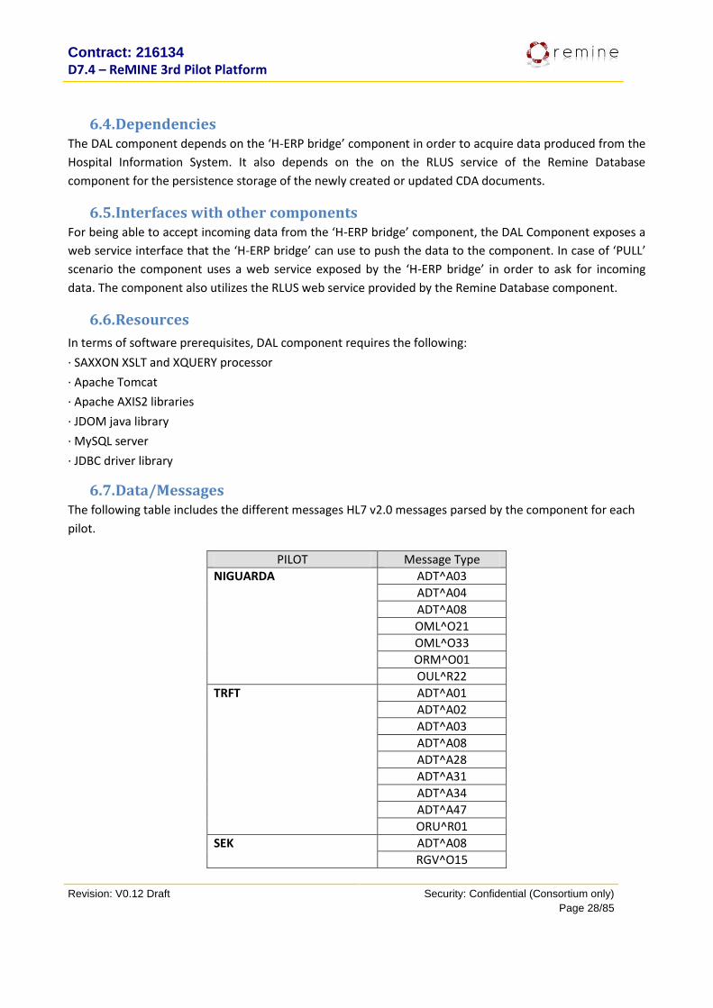
6.7. Data/Messages The following table includes the different messages HL7 v2.0 messages parsed by the component for each
pilot.
PILOT Message Type
NIGUARDA ADT^A03
ADT^A04
ADT^A08
OML^O21
OML^O33
ORM^O01
OUL^R22
TRFT ADT^A01
ADT^A02
ADT^A03
ADT^A08
ADT^A28
ADT^A31
ADT^A34
ADT^A47
ORU^R01
SEK ADT^A08
RGV^O15

Contract: 216134
D7.4 – ReMINE 3rd Pilot Platform
Revision: V0.12 Draft Security: Confidential (Consortium only)
Page 29/85
BAR^P12
SACCO ADT^A04
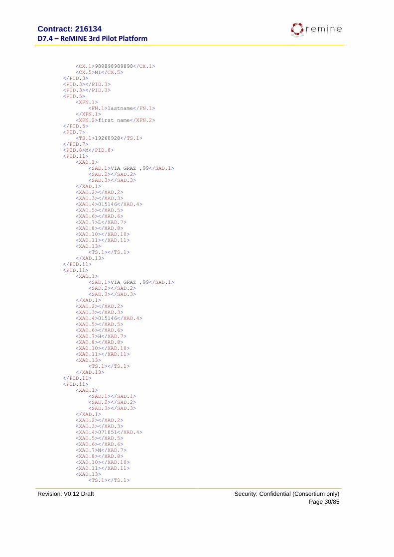
An example of a sample ADT^A04 from the Niguarda pilot and its corresponding CDA Document created by
the Parser-Transformer module is shown below.
ADT^A04 message <?xml version="1.0" encoding="UTF-8"?>
<ADT_GENERICO xmlns="urn:hl7-org:v2xml" xmlns:xsi="http://www.w3.org/2001/XMLSchema-instance">
<MSH>
<MSH.1>|</MSH.1>
<MSH.2>^~&|</MSH.2>
<MSH.3>
<HD.1>PIESSE</HD.1>
</MSH.3>
<MSH.4>
<HD.1>CBIM</HD.1>
</MSH.4>
<MSH.5>
<HD.1>REMINE</HD.1>
</MSH.5>
<MSH.6>
<HD.1>REMINE</HD.1>
</MSH.6>
<MSH.7>
<TS.1>201009011945</TS.1>
</MSH.7>
<MSH.9>
<MSG.1>ADT</MSG.1>
<MSG.2>A04</MSG.2>
</MSH.9>
<MSH.10>355c6908-ffe3-4690-9c77-42deb8e58798</MSH.10>
<MSH.11>
<PT.1>P</PT.1>
</MSH.11>
<MSH.12>
<VID.1>2.5</VID.1>
</MSH.12>
</MSH>
<EVN>
<EVN.1>A04</EVN.1>
<EVN.2>
<TS.1>201009011945</TS.1>
</EVN.2>
</EVN>
<PID>
<PID.3>
<CX.1>456456456</CX.1>
<CX.4>
<HD.1>PK</HD.1>
</CX.4>
<CX.5>FI</CX.5>
<CX.6>
<HD.1>BDA</HD.1>
</CX.6>
<CX.9>
<CWE.1>R</CWE.1>
</CX.9>
</PID.3>
<PID.3>
<CX.1>321321321</CX.1>
<CX.5>SS</CX.5>
</PID.3>
<PID.3>
Contract: 216134
D7.4 – ReMINE 3rd Pilot Platform
Revision: V0.12 Draft Security: Confidential (Consortium only)
Page 30/85
<CX.1>989898989898</CX.1>
<CX.5>NI</CX.5>
</PID.3>
<PID.3></PID.3>
<PID.3></PID.3>
<PID.5>
<XPN.1>
<FN.1>lastname</FN.1>
</XPN.1>
<XPN.2>first name</XPN.2>
</PID.5>
<PID.7>
<TS.1>19260928</TS.1>
</PID.7>
<PID.8>M</PID.8>
<PID.11>
<XAD.1>
<SAD.1>VIA GRAZ ,99</SAD.1>
<SAD.2></SAD.2>
<SAD.3></SAD.3>
</XAD.1>
<XAD.2></XAD.2>
<XAD.3></XAD.3>
<XAD.4>015146</XAD.4>
<XAD.5></XAD.5>
<XAD.6></XAD.6>
<XAD.7>L</XAD.7>
<XAD.8></XAD.8>
<XAD.10></XAD.10>
<XAD.11></XAD.11>
<XAD.13>
<TS.1></TS.1>
</XAD.13>
</PID.11>
<PID.11>
<XAD.1>
<SAD.1>VIA GRAZ ,99</SAD.1>
<SAD.2></SAD.2>
<SAD.3></SAD.3>
</XAD.1>
<XAD.2></XAD.2>
<XAD.3></XAD.3>
<XAD.4>015146</XAD.4>
<XAD.5></XAD.5>
<XAD.6></XAD.6>
<XAD.7>H</XAD.7>
<XAD.8></XAD.8>
<XAD.10></XAD.10>
<XAD.11></XAD.11>
<XAD.13>
<TS.1></TS.1>
</XAD.13>
</PID.11>
<PID.11>
<XAD.1>
<SAD.1></SAD.1>
<SAD.2></SAD.2>
<SAD.3></SAD.3>
</XAD.1>
<XAD.2></XAD.2>
<XAD.3></XAD.3>
<XAD.4>071051</XAD.4>
<XAD.5></XAD.5>
<XAD.6></XAD.6>
<XAD.7>N</XAD.7>
<XAD.8></XAD.8>
<XAD.10></XAD.10>
<XAD.11></XAD.11>
<XAD.13>
<TS.1></TS.1>
Contract: 216134
D7.4 – ReMINE 3rd Pilot Platform
Revision: V0.12 Draft Security: Confidential (Consortium only)
Page 31/85
</XAD.13>
</PID.11>
<PID.13>
<XTN.3>PH</XTN.3>
<XTN.12>8787878787</XTN.12>
</PID.13>
<PID.14>
<XTN.3>PH</XTN.3>
</PID.14>
<PID.18>
<CX.1>6546546545654</CX.1>
</PID.18>
<PID.19>456465465</PID.19>
<PID.23>071051</PID.23>
<PID.26>
<CE.2>100</CE.2>
</PID.26>
<PID.28>
<CE.2>100</CE.2>
</PID.28>
<PID.33>
<TS.1>200704020756</TS.1>
</PID.33>
</PID>
<PV1>
<PV1.2>E</PV1.2>
<PV1.3>
<PL.1>300</PL.1>
</PV1.3>
<PV1.4>E</PV1.4>
<PV1.19>
<CX.1>2010563265</CX.1>
</PV1.19>
<PV1.44>
<TS.1>201009011936</TS.1>
</PV1.44>
</PV1>
<PV2>
<PV2.3>
<CE.1>32</CE.1>
<CE.2>DISTURBI NEUROLOGICI FOCALI E CONVULSIONI - DEFICIT DI FORZA UNO O PIU' ARTI
- INSORTO DA > 4 ORE - cardiopatico noto, diabetico NID. vomito.</CE.2>
</PV2.3>
<PV2.25>V</PV2.25>
</PV2>
</ADT_GENERICO>
CDA Document <?xml version="1.0" encoding="UTF-8" standalone="no"?>
<ClinicalDocument xmlns="urn:hl7-org:v3" xmlns:xsd="http://www.w3.org/2001/XMLSchema"
xmlns:xsi="http://www.w3.org/2001/XMLSchema-instance">
<typeId extension="POCD_HD000040" root="2.16.840.1.113883.1.3"/>
<templateId root="2.16.840.1.113883.3.27.1776"/>
<id extension="355c6908-ffe3-4690-9c77-42deb8e58798" root="2.16.840.1.113883.3.270.1.1"/>
<code code="51855-5" codeSystem="2.16.840.1.113883.6.1" codeSystemName="LOINC"
displayName="Clinical note"/>
<effectiveTime value="201009011945"/>
<confidentialityCode code="N" codeSystem="2.16.840.1.113883.5.25"
codeSystemName="Confidentiality" displayName="Normal"/>
<setId extension="456456456" root="2.16.840.1.113883.3.270.1.2"/>
<versionNumber value="1"/>
<recordTarget>
<patientRole>
<id extension="456456456" root="2.16.840.1.113883.3.270.1.3"/>
<patient>
<name>
<given>lastname</given>
Contract: 216134
D7.4 – ReMINE 3rd Pilot Platform
Revision: V0.12 Draft Security: Confidential (Consortium only)
Page 32/85
<family>first name</family>
</name>
<administrativeGenderCode code="M" codeSystem="2.16.840.1.113883.5.1"
codeSystemName="AdministrativeGender" displayName="Male"/>
<birthTime value="19260928"/>
</patient>
</patientRole>
</recordTarget>
<author>
<time value="200704020756"/>
<assignedAuthor>
<id extension="PIESSE" root="2.16.840.1.113883.3.270"/>
<representedOrganization>
<id root="2.16.840.1.113883.3.270"/>
</representedOrganization>
</assignedAuthor>
</author>
<custodian>
<assignedCustodian>
<representedCustodianOrganization>
<id root="2.16.840.1.113883.3.270"/>
<name>CBIM</name>
</representedCustodianOrganization>
</assignedCustodian>
</custodian>
<componentOf>
<encompassingEncounter>
<code code="338709012" codeSystem="2.16.840.1.113883.6.96"
codeSystemName="SNOMED-CT" displayName="Triage">
<qualifier>
<name code="388521012" codeSystem="2.16.840.1.113883.6.96"
codeSystemName="SNOMED-CT" displayName="Priority"/>
<value code="394848005" codeSystem="2.16.840.1.113883.6.69"
codeSystemName="SNOMED-CT" displayName="Normal priority"/>
</qualifier>
</code>
<effectiveTime value="201009011936"/>
</encompassingEncounter>
</componentOf>
<component>
<structuredBody>
<component>
<section>
<code code="11496-7" codeSystem="2.16.840.1.113883.6.1"
codeSystemName="LOINC" displayName="Assessment"/>
<title>Patient visit additional information</title>
<entry>
<observation classCode="COND" moodCode="EVN">
<code code="8319008"
codeSystem="2.16.840.1.113883.6.96" codeSystemName="SNOMED CT" displayName="Principal diagnosis"/>
<text>DISTURBI NEUROLOGICI FOCALI E CONVULSIONI
- DEFICIT DI FORZA UNO O PIU' ARTI - INSORTO DA > 4 ORE - cardiopatico noto, diabetico NID.
vomito.</text>
<statusCode code="completed"/>
<targetSiteCode code="449662019"
codeSystem="2.16.840.1.113883.6.69" codeSystemName="SNOMED-CT" displayName="Neurological disorder"/>
</observation>
</entry>
</section>
</component>
</structuredBody>
</component>
</ClinicalDocument>
Contract: 216134
D7.4 – ReMINE 3rd Pilot Platform
Revision: V0.12 Draft Security: Confidential (Consortium only)
Page 33/85
6.8. Installation instructions DAL is consisted of a single file packaged as a Web application archive. To install it to the Apache Tomcat
server it is only required that is copied inside the “webapps” folder under the installed Tomcat folder tree
structure.
7. Intalio Processes
7.1. Purpose A business process is a collection of related, structured activities or tasks that produce a specific service or
product to accomplish a specific organizational goal. It often can be visualized with a flowchart as a
sequence of activities. Business process modeling (BPM) in software engineering is the activity of
representing processes of an enterprise, so that the current process may be analyzed and improved. The
business processes representing the business logic of the different clinical procedures have been developed
under Intalio platform using Business Process Modeling Notation Language (BPMN). The aim of this
language is to facilitate communication between IT and line-of-business (LOB).
BPM offers several key advantages to define the business processes of an organization. BPM makes a
business process absolutely transparent, greatly improving visibility and efficiency. Bottlenecks can literally
be seen, and removed. It can show where the most delays are occurring, and where is each transaction
stuck as it passes from one stage to another. Data about each and every transaction is logged and can be
retrieved as and when required. Therefore, it is possible to analyze accurately what happened. Referencing
is also easier as embedded searches allow for data to be picked up as required for study.
The BPMN is translated to Business Process Execution Language (BPEL), a standard executable language to
be processed for a server.

Contract: 216134
D7.4 – ReMINE 3rd Pilot Platform
Revision: V0.12 Draft Security: Confidential (Consortium only)
Page 34/85
Figure 1. Business Process Example
7.2. 2nd and 3rd Prototype Functionalities Comparison The 3rd Prototype functionality highly increases the quality of service provided by the platform. As the core
of the application an improvement in any subcomponent drives to a modification and consequently an
enhancement of the business processes. Moreover the processes have been enriched to improve the
functionality and to deal with potential failures. Mainly the enhancements can be listed as follows:
Scenarios enhancement for a better description of the clinical business procedures
Fully Integration with the sub-modules of ReMINE
Processing all messages coming from H-ERP Bridge/DAL
Improvement of the outcoming data storage (quantity and quality): the information stored in the internal database and the data related to Key Performance Indicators (KPIs)
Development of RLUS Wrapper Web Service for the Process Mapper that encapsulates RLUS client business logic
Changes in processes according to enhancements in sub-modules and optimization
Recovering from some failures due to input data or the unavailable services
Integration with new business rules to offer more flexibility in the clinical pathways
7.3. Dependencies The processes define the clinical pathway and coordinate the remainder modules of the system. We can
find dependencies between the business processes and all the single modules of ReMINE. Consequently,
the dependencies between the processes and the sub-systems of the platform are really strong. The
Contract: 216134
D7.4 – ReMINE 3rd Pilot Platform
Revision: V0.12 Draft Security: Confidential (Consortium only)
Page 35/85
malfunction of some modules can produce failures in the whole business process. This tight dependency is
intrinsic to Software Oriented Architecture (SOA) systems.
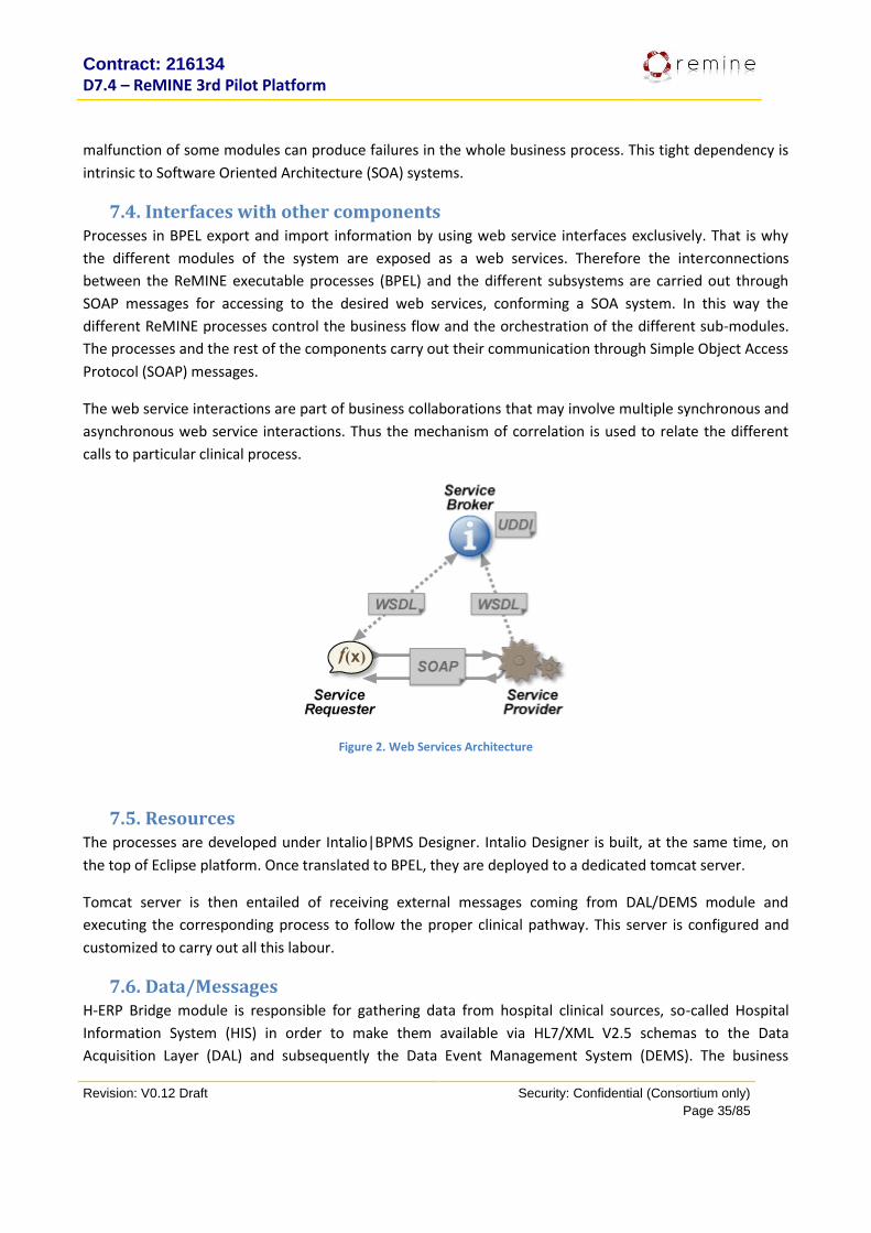
7.4. Interfaces with other components Processes in BPEL export and import information by using web service interfaces exclusively. That is why
the different modules of the system are exposed as a web services. Therefore the interconnections
between the ReMINE executable processes (BPEL) and the different subsystems are carried out through
SOAP messages for accessing to the desired web services, conforming a SOA system. In this way the
different ReMINE processes control the business flow and the orchestration of the different sub-modules.
The processes and the rest of the components carry out their communication through Simple Object Access
Protocol (SOAP) messages.
The web service interactions are part of business collaborations that may involve multiple synchronous and
asynchronous web service interactions. Thus the mechanism of correlation is used to relate the different
calls to particular clinical process.
Figure 2. Web Services Architecture
7.5. Resources The processes are developed under Intalio|BPMS Designer. Intalio Designer is built, at the same time, on
the top of Eclipse platform. Once translated to BPEL, they are deployed to a dedicated tomcat server.
Tomcat server is then entailed of receiving external messages coming from DAL/DEMS module and
executing the corresponding process to follow the proper clinical pathway. This server is configured and
customized to carry out all this labour.
7.6. Data/Messages H-ERP Bridge module is responsible for gathering data from hospital clinical sources, so-called Hospital
Information System (HIS) in order to make them available via HL7/XML V2.5 schemas to the Data
Acquisition Layer (DAL) and subsequently the Data Event Management System (DEMS). The business
Contract: 216134
D7.4 – ReMINE 3rd Pilot Platform
Revision: V0.12 Draft Security: Confidential (Consortium only)
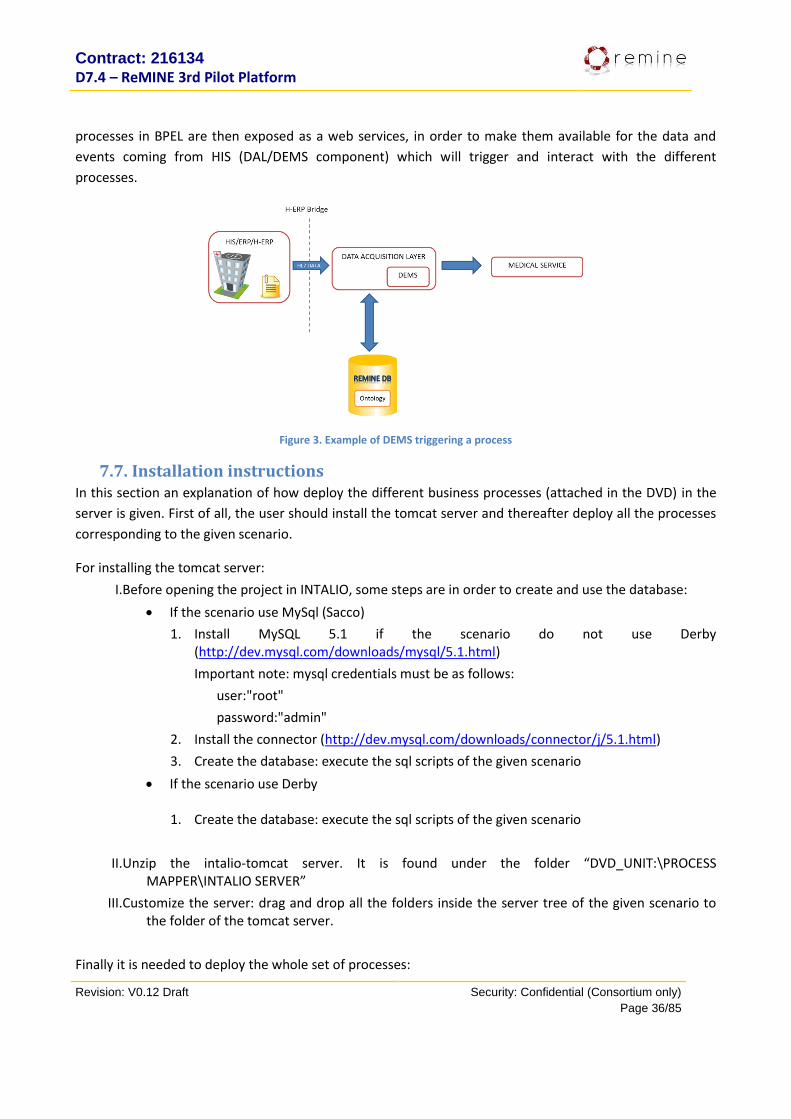
Page 36/85
processes in BPEL are then exposed as a web services, in order to make them available for the data and
events coming from HIS (DAL/DEMS component) which will trigger and interact with the different
processes.
Figure 3. Example of DEMS triggering a process
7.7. Installation instructions In this section an explanation of how deploy the different business processes (attached in the DVD) in the
server is given. First of all, the user should install the tomcat server and thereafter deploy all the processes
corresponding to the given scenario.
For installing the tomcat server:
I.Before opening the project in INTALIO, some steps are in order to create and use the database:
If the scenario use MySql (Sacco)
1. Install MySQL 5.1 if the scenario do not use Derby (http://dev.mysql.com/downloads/mysql/5.1.html)
Important note: mysql credentials must be as follows:
user:"root"
password:"admin"
2. Install the connector (http://dev.mysql.com/downloads/connector/j/5.1.html)
3. Create the database: execute the sql scripts of the given scenario
If the scenario use Derby
1. Create the database: execute the sql scripts of the given scenario
II.Unzip the intalio-tomcat server. It is found under the folder “DVD_UNIT:\PROCESS MAPPER\INTALIO SERVER”
III.Customize the server: drag and drop all the folders inside the server tree of the given scenario to the folder of the tomcat server.
Finally it is needed to deploy the whole set of processes:
Contract: 216134
D7.4 – ReMINE 3rd Pilot Platform
Revision: V0.12 Draft Security: Confidential (Consortium only)
Page 37/85
1. Open Intalio|Designer and import the projects.
2. Select all and with right click in the project folders select the option “Clean and build now”.
3. Deploy the projects in the server.
8. ReMINE Database Metadatabase services are structured in 2 modules: RLUS (Retrieve Locate and Update Service) and
TOS (Taxonomy and Ontology Service). These modules are designed as web services using SQL2008 for data
persistence.
RLUS API is the main interface for the database. It is based on HL7 service contracts. RLUS works with
two databases: Metadatabase and Data Repository. Having a RLUS entry, its metadata will be in the first
database and its content in the second. The content can be binary or simply a reference to where the real
data persists thus the name of metadatabase. RLUS is used to provide for the location, retrieval, and
update of clinical and non-clinical information. In ReMINE project RLUS represents the API interface layer of
the database allowing the management of documents (clinical and non-clinical) with dynamic structure.
RLUS can be configured to accept different metadata information for a specific type of information
(documents) trough the configuration of slots (metadata information).
The taxonomy and ontology service (TOS) is based on a HL7 CTS1 (Common Terminology Services v1)
implementation. The Health Level Seven Version 3 standards are based on a Reference Information Model
(RIM) which is flexible and general in structure. Representation of information within this model is
dependent on the availability of terminological resources which can be used to populate the properties of
the model with appropriate semantic content. Whenever possible, the HL7 Version 3 standard references
existing terminological resources instead of attempting to create a new resource within the standard itself.
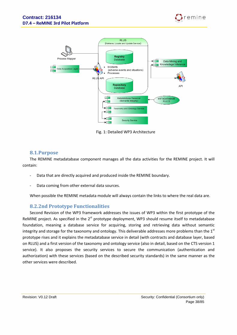
The metadatabase services represent de core of WP3 modules as seen in the following detailed WP3
architecture diagram:
Contract: 216134
D7.4 – ReMINE 3rd Pilot Platform
Revision: V0.12 Draft Security: Confidential (Consortium only)
Page 38/85
Fig. 1: Detailed WP3 Architecture
8.1. Purpose The REMINE metadatabase component manages all the data activities for the REMINE project. It will
contain:
- Data that are directly acquired and produced inside the REMINE boundary.
- Data coming from other external data sources.
When possible the REMINE metadata module will always contain the links to where the real data are.
8.2. 2nd Prototype Functionalities Second Revision of the WP3 framework addresses the issues of WP3 within the first prototype of the
ReMINE project. As specified in the 2st prototype deployment, WP3 should resume itself to metadatabase
foundation, meaning a database service for acquiring, storing and retrieving data without semantic
integrity and storage for the taxonomy and ontology. This deliverable addresses more problems than the 1st
prototype rises and it explains the metadatabase service in detail (with contracts and database layer, based
on RLUS) and a first version of the taxonomy and ontology service (also in detail, based on the CTS version 1
service). It also proposes the security services to secure the communication (authentication and
authorization) with these services (based on the described security standards) in the same manner as the
other services were described.
Contract: 216134
D7.4 – ReMINE 3rd Pilot Platform
Revision: V0.12 Draft Security: Confidential (Consortium only)
Page 39/85
8.3. 3rd Prototype Functionalities Third Revision of the WP3 framework represents the last steps that were taken for WP3 framework in
the form of WP3 service enhancements:
- Audit service completion: all WP3 services are audit trailed on their main operations
- WS-Eventing development on RLUS service to be used in the data mining and knowledge inference
module
- Completion of the metadatabase reasoner in the form of SIMP designer (designer for the semantic
signifiers) and the reasoner itself as an executer for these templates inside the RLUS
implementation
- RLUS Wrapper Web Service for the Process Mapper that encapsulates RLUS client business logic
8.4. Dependencies The metadatabase as a concept doesn’t necessarily depend on any other component of the
ReMINE project, but the other way around. However, RLUS data structure is based on the metadata
concept (called slots), allowing it to change easily by matter of configuration to the needs of the
metadatabase consumers.
Master Patient Index service works as well with metadata (called traits) adapting to new patient
information while TOS has a strict internal data representation and yet allowing it to store various
ontologies with different structures.
8.5. Interfaces with other components Access to the metadatabase is done only trough the existing API of the web services: RLUS for clinical
and non clinical documents, MPI for patient management, QED to easily query RLUS data and TOS to
manage and query the ontology.
8.6. Resources The metadata structure of the metadatabase (RLUS tables in a relationship database) is described in detail in the ‘Data section’. Access speed is very important for this database. The repository database of RLUS will contain all the binary data, thus size is very important for this database. Required resources depend on the size of the data stored. The server must run a Microsoft SQL 2005 or SQL 2008 instance. RLUS service will require at least the following resources:
- 1GB RAM - 100MB hard disk space - 1GHz CPU - Microsoft .NET 3.5 Framework SP1
Contract: 216134
D7.4 – ReMINE 3rd Pilot Platform
Revision: V0.12 Draft Security: Confidential (Consortium only)
Page 40/85
The server that runs the MS-SQL server will comply with Microsoft’s hardware requirements for SQL2005 (or SQL2008). Regarding storage space, it is premature to estimate the space that the database will require for the whole REMINE project.
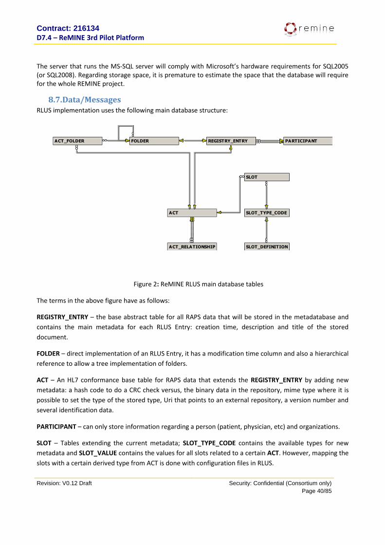
8.7. Data/Messages RLUS implementation uses the following main database structure:
ACT
ACT_FOLDER
ACT_RELATIONSHIP
FOLDER PARTICIPANTREGISTRY_ENTRY
SLOT
SLOT_DEFINITION
SLOT_TYPE_CODE
Figure 2: ReMINE RLUS main database tables
The terms in the above figure have as follows:
REGISTRY_ENTRY – the base abstract table for all RAPS data that will be stored in the metadatabase and
contains the main metadata for each RLUS Entry: creation time, description and title of the stored
document.
FOLDER – direct implementation of an RLUS Entry, it has a modification time column and also a hierarchical
reference to allow a tree implementation of folders.
ACT – An HL7 conformance base table for RAPS data that extends the REGISTRY_ENTRY by adding new
metadata: a hash code to do a CRC check versus, the binary data in the repository, mime type where it is
possible to set the type of the stored type, Uri that points to an external repository, a version number and
several identification data.
PARTICIPANT – can only store information regarding a person (patient, physician, etc) and organizations.
SLOT – Tables extending the current metadata; SLOT_TYPE_CODE contains the available types for new
metadata and SLOT_VALUE contains the values for all slots related to a certain ACT. However, mapping the
slots with a certain derived type from ACT is done with configuration files in RLUS.
Contract: 216134
D7.4 – ReMINE 3rd Pilot Platform
Revision: V0.12 Draft Security: Confidential (Consortium only)
Page 41/85
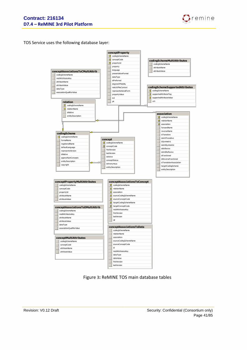
TOS Service uses the following database layer:
associationcodingSchemeName
relationName
association
forwardName
reverseName
isTransitive
isAntiTransitive
isSymmetric
isAntiSymmetric
isReflexive
isAntiReflexive
isFunctional
isReverseFunctional
isTranslationAssociation
targetCodingScheme
entityDescription
codingSchemecodingSchemeName
formalName
registeredName
defaultLanguage
representsVersion
isNative
approxNumConcepts
entityDescription
copyright
codingSchemeMultiAttributescodingSchemeName
attributeName
attributeValue
codingSchemeSupportedAttributescodingSchemeName
supportedAttributeTag
supportedAttributeValue
urn
conceptcodingSchemeName
conceptCode
firstVersion
lastVersion
isActive
conceptStatus
isAnonymous
entityDescription
conceptAssociationsToCMultiAttribcodingSchemeName
multiAttributesKey
attributeName
attributeValue
dataType
associationQualifierValue
conceptAssociationsToConceptcodingSchemeName
relationName
association
sourceCodingSchemeName
sourceConceptCode
targetCodingSchemeName
targetConceptCode
multiAttributesKey
firstVersion
lastVersion
dir
conceptAssociationsToDatacodingSchemeName
relationName
association
sourceCodingSchemeName
sourceConceptCode
id
multiAttributesKey
dataType
dataValue
firstVersion
lastVersion
conceptAssociationsToDMultiAttribcodingSchemeName
multiAttributesKey
attributeName
attributeValue
dataType
associationQualifierValue
conceptMultiAttributescodingSchemeName
conceptCode
attributeName
attributeValue
conceptPropertycodingSchemeName
conceptCode
propertyId
property
language
presentationFormat
dataType
isPreferred
degreeOfFidelity
matchIfNoContext
representationalForm
propertyValue
aui
pk
conceptPropertyMultiAttributescodingSchemeName
conceptCode
propertyId
attributeName
attributeValue
relationcodingSchemeName
relationName
isNative
entityDescription
Figure 3: ReMINE TOS main database tables

Contract: 216134
D7.4 – ReMINE 3rd Pilot Platform
Revision: V0.12 Draft Security: Confidential (Consortium only)
Page 42/85
Table Field Description
codingScheme approxNumConcepts An approximation of the number of codes in the coding scheme.
This approximation can be used by interface software to determine
whether to return complete lists of coding scheme content as a
single block or to take alternate action. This field is strictly a "hint"
and should never be counted on to have an exact value.
codingSchemeName This is a short "local name" that is used to reference this specific
coding scheme within the context of the containing service. There
is no guarantee that the same local name will always be used for
the same coding scheme. One service or repository may identify
SNOMED-CT as "SCT", and another as "Snomed", etc. The
registeredName of the coding scheme should always be used to
reference the coding scheme from outside the context of the
containing service. SNOMED-CT should always be referenced
externally using the official urn, "urn:oid:2.16.840.1.113883.6.96".
defaultLanguage The local name of the default language used by the coding scheme.
This attribute must be a local name in a corresponding
supportedLanguage mapping entry. As an example:
<codingScheme codingScheme="NCI" ... defaultLanguage="en"...>
would correspond to
<supportedLanguage
urn="urn:oid:2.16.840.1.113883.6.84:en">en</supportedLanguage>
formalName The official name of the coding scheme as defined by the primary
authors. Example: "SNOMED Clinical Terms"
isNative Used to indicate that this coding scheme is the primary coding
scheme for a containing service. The intent of this attribute was to
allow "consuming" coding schemes such as the NCI Thesaurus or
the UMLS to be identified as the primary scheme supported by a
service and that other coding schemes were secondary.
registeredName The official URN of this coding scheme. Example:
<codingScheme codingScheme="NCI"
registeredName="urn:oid:2.16.840.1.113883.3.26.1.1"...>
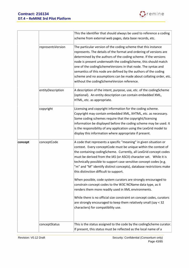
Contract: 216134
D7.4 – ReMINE 3rd Pilot Platform
Revision: V0.12 Draft Security: Confidential (Consortium only)
Page 43/85
This the identifier that should always be used to reference a coding
scheme from external web pages, data base records, etc.
representsVersion The particular version of the coding scheme that this instance
represents. The details of the format and ordering of versions are
determined by the authors of the coding scheme. If the versions
node is present underneath the codingScheme, this should match
one of the codingSchemeVersions in that node. The syntax and
semantics of this node are defined by the authors of the coding
scheme and no assumptions can be made about collating order, etc.
without the codingSchemeVersion reference.
entityDescription A description of the intent, purpose, use, etc. of the codingScheme
(optional). An entity description can contain embedded XML,
HTML, etc. as appropriate.
copyright Licensing and copyright information for the coding scheme.
Copyright may contain embedded XML, XHTML, etc. as necessary.
Some coding schemes require that the copyright/licensing
information be displayed before the coding scheme may be used. It
is the responsibility of any application using the LexGrid model to
display this information where appropriate if present.
concept conceptCode
A code that represents a specific "meaning" in given situation or
context. Every conceptCode must be unique within the context of
the containing codingScheme. Currently, all LexGrid concept codes
must be derived from the IA5 (or ASCII) character set. While it is
technically possible to support case sensitive concept codes (e.g.
"m" and "M" identify distinct concepts), database restrictions make
this distinction difficult to support.
When possible, code system curators are strongly encouraged to
constrain concept codes to the W3C NCName data type, as it
renders them more readily used in XML environments.
While there is no official size constraint on concept codes, curators
are strongly encouraged to keep them relatively small (say < 32
characters) for compatibility use.
conceptStatus This is the status assigned to the code by the codingScheme curator.
If present, this status must be reflected as the local name of a
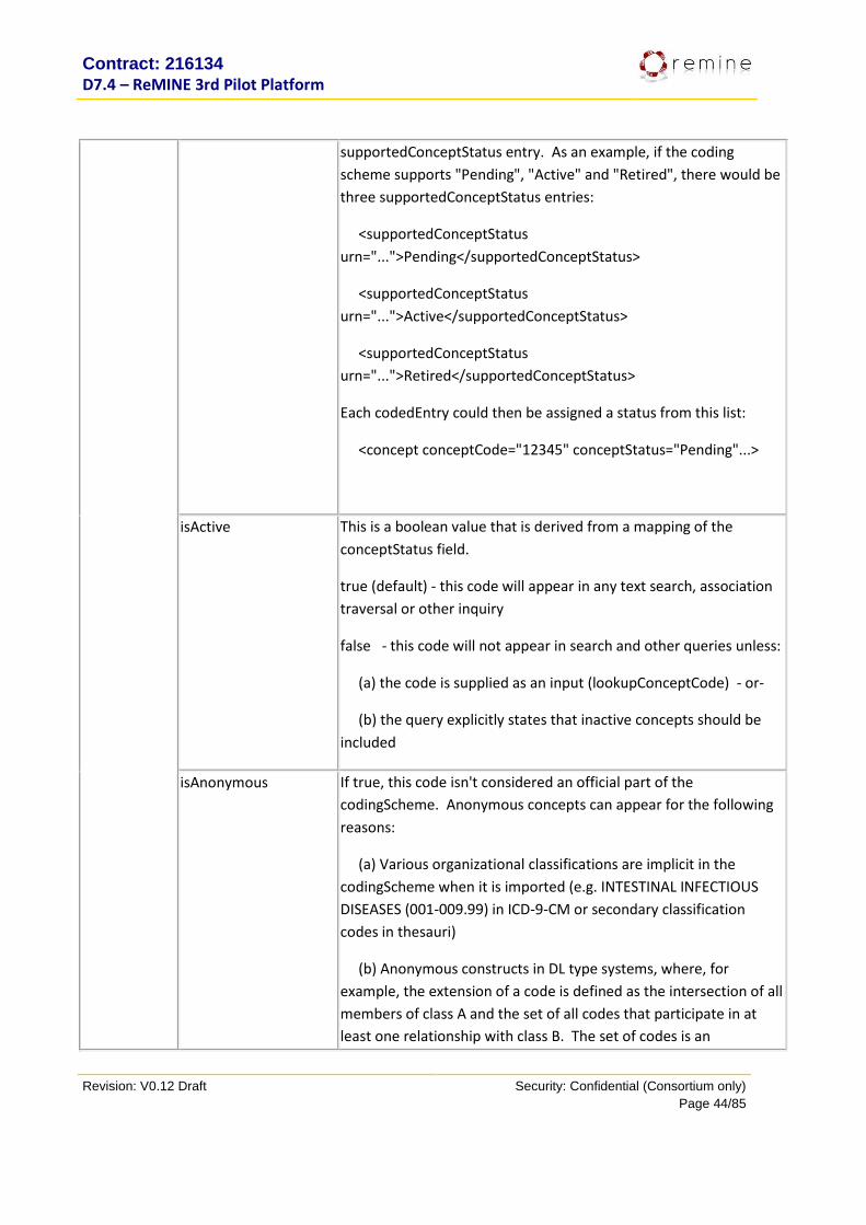
Contract: 216134
D7.4 – ReMINE 3rd Pilot Platform
Revision: V0.12 Draft Security: Confidential (Consortium only)
Page 44/85
supportedConceptStatus entry. As an example, if the coding
scheme supports "Pending", "Active" and "Retired", there would be
three supportedConceptStatus entries:
<supportedConceptStatus
urn="...">Pending</supportedConceptStatus>
<supportedConceptStatus
urn="...">Active</supportedConceptStatus>
<supportedConceptStatus
urn="...">Retired</supportedConceptStatus>
Each codedEntry could then be assigned a status from this list:
<concept conceptCode="12345" conceptStatus="Pending"...>
isActive This is a boolean value that is derived from a mapping of the
conceptStatus field.
true (default) - this code will appear in any text search, association
traversal or other inquiry
false - this code will not appear in search and other queries unless:
(a) the code is supplied as an input (lookupConceptCode) - or-
(b) the query explicitly states that inactive concepts should be
included
isAnonymous
If true, this code isn't considered an official part of the
codingScheme. Anonymous concepts can appear for the following
reasons:
(a) Various organizational classifications are implicit in the
codingScheme when it is imported (e.g. INTESTINAL INFECTIOUS
DISEASES (001-009.99) in ICD-9-CM or secondary classification
codes in thesauri)
(b) Anonymous constructs in DL type systems, where, for
example, the extension of a code is defined as the intersection of all
members of class A and the set of all codes that participate in at
least one relationship with class B. The set of codes is an
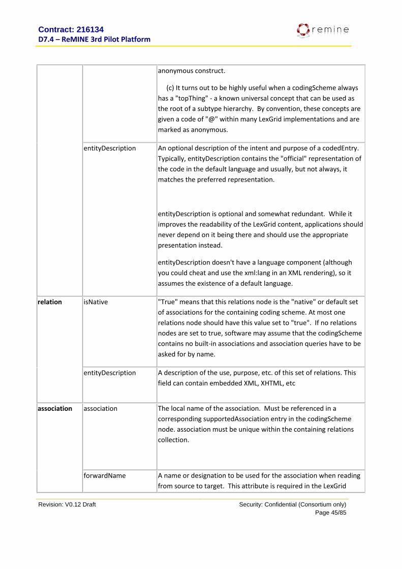
Contract: 216134
D7.4 – ReMINE 3rd Pilot Platform
Revision: V0.12 Draft Security: Confidential (Consortium only)
Page 45/85
anonymous construct.
(c) It turns out to be highly useful when a codingScheme always
has a "topThing" - a known universal concept that can be used as
the root of a subtype hierarchy. By convention, these concepts are
given a code of "@" within many LexGrid implementations and are
marked as anonymous.
entityDescription An optional description of the intent and purpose of a codedEntry.
Typically, entityDescription contains the "official" representation of
the code in the default language and usually, but not always, it
matches the preferred representation.
entityDescription is optional and somewhat redundant. While it
improves the readability of the LexGrid content, applications should
never depend on it being there and should use the appropriate
presentation instead.
entityDescription doesn't have a language component (although
you could cheat and use the xml:lang in an XML rendering), so it
assumes the existence of a default language.
relation isNative
"True" means that this relations node is the "native" or default set
of associations for the containing coding scheme. At most one
relations node should have this value set to "true". If no relations
nodes are set to true, software may assume that the codingScheme
contains no built-in associations and association queries have to be
asked for by name.
entityDescription
A description of the use, purpose, etc. of this set of relations. This
field can contain embedded XML, XHTML, etc
association association
The local name of the association. Must be referenced in a
corresponding supportedAssociation entry in the codingScheme
node. association must be unique within the containing relations
collection.
forwardName A name or designation to be used for the association when reading
from source to target. This attribute is required in the LexGrid

Contract: 216134
D7.4 – ReMINE 3rd Pilot Platform
Revision: V0.12 Draft Security: Confidential (Consortium only)
Page 46/85
model because it is often possible to label associations in a way that
is misleading. As an example, an association might be given the
local name "part". The assertion, "part(A,B)" is ambiguous here -
does it mean that A is a part of B or B is a part of A? The forward
name should unambiguously represent the intent of the association
in the language of the coding scheme. As an example, if the "part"
association is intended to represent the fact that the whole contains
the part, the forward name should be something like "hasPart".
Similarly, if the association is intended to represent that the part is a
part or component of the whole, the forward name should be
something akin to "isPartOf".
If the association is formally defined as a code in some coding
scheme, it is strongly recommended that it have a set of language-
specific forwardName and, if applicable, reverseName properties.
Without these properties and the associated descriptions it is easy
to make errors when determining which code fits the source and
which the target slot of a given association
isSymmetric and
isAntiSymmetric
isSymmetric "true" states that r(A,B) implies r(B,A). False states that
it is possible to have r(A,B) without r(B,A).
(a) symmetric associations are always navigable.
(b) the forwardName and reverseName of symmetric associations
should always be the same.
(c) The domain and range of symmetric associations must be
identical. Associations without the same domain and range are, by
default, non- symmetric.
isAntiSymmetric"true" states that r(A,B) and r(B,A) can never both
be true. The trivial case of antiSymmetry is the case where the
domain and range are mutually exclusive, and it isn't really
necessary to state anything about symmetry in this case. The
interesting case is where there is partial or complete overlap. The
association "hasChild" (referring to people, birth and the like) is
antiSymmetric.(Note - think about this. On the class level, it really
*is* symmetric...), while the association sibling is.
isReflexive and
isAntiReflexive
isReflexive "true" states that for any member A of the domain of the
association r, r(A,A) is true. False states that it is possible that r(A,A)
may not be true for all members of the domain and, in fact, it may

Contract: 216134
D7.4 – ReMINE 3rd Pilot Platform
Revision: V0.12 Draft Security: Confidential (Consortium only)
Page 47/85
be true for none.
isAntiReflexive "true" states that r(A,A) can never be true for any
member of the domain of r.
The most common purpose of the reflexive association is to define
exactly what is intended by the "subtype" association. One of the
questions that has to be asked about a subtype association is
whether is "proper" or "improper" in the mathematical sense - is a
class considered to be a subtype of itself, according to the authors
of the terminology. If it is, isReflexive would be "true" and, if not,
isAntiReflexive would be "true".
isFunctional and
isReferseFunctional
isFunctional and isReverseFunctional correspond to the
FunctionalProperty and InverseFunctionalProperty as defined in the
Web Ontology Language (OWL). An association defined with
isFunctional true has at most one association target for any given
source. An association defined with isInverseFunctional true has at
most one source associated with a given target.
isTranslationAssociation
This flag indicates that the association represents a "translation" or
"mapping" between the containing coding scheme and the coding
scheme named in targetCodingScheme. It is used by service
software to determine which association is to be used for coding
scheme mapping.
reverseName
The reverse name of the association - the text that would be used if
reading the association from target to source. See: forwardName
for a detailed description of the purpose of this attribute. Note that
the reverse name may not always be applicable - see isNavigable for
further details.
entityDescription
A description of the association. This field can contain embedded
XML, XHTML, etc.
targetCodingScheme
The local name of the codingScheme that, unless otherwise
specified, the targetConcept codes are drawn from. Must be a local
name in a supportedCodingScheme entry in the codingScheme
header.
For MPI, the database layer follows:
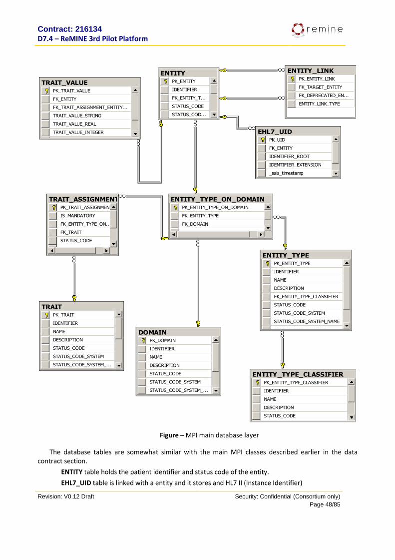
Contract: 216134
D7.4 – ReMINE 3rd Pilot Platform
Revision: V0.12 Draft Security: Confidential (Consortium only)
Page 48/85
DOMAINPK_DOMAIN
IDENTIFIER
NAME
DESCRIPTION
STATUS_CODE
STATUS_CODE_SYSTEM
STATUS_CODE_SYSTEM_...
ENTITY_TYPEPK_ENTITY_TYPE
IDENTIFIER
NAME
DESCRIPTION
FK_ENTITY_TYPE_CLASSIFIER
STATUS_CODE
STATUS_CODE_SYSTEM
STATUS_CODE_SYSTEM_NAME
STATUS_DISPLAY_NAME
ENTITY_TYPE_CLASSIFIERPK_ENTITY_TYPE_CLASSIFIER
IDENTIFIER
NAME
DESCRIPTION
STATUS_CODE
STATUS_CODE_SYSTEM
ENTITY_TYPE_ON_DOMAINPK_ENTITY_TYPE_ON_DOMAIN
FK_ENTITY_TYPE
FK_DOMAIN
_ssis_timestamp
TRAITPK_TRAIT
IDENTIFIER
NAME
DESCRIPTION
STATUS_CODE
STATUS_CODE_SYSTEM
STATUS_CODE_SYSTEM_...
ENTITYPK_ENTITY
IDENTIFIER
FK_ENTITY_T...
STATUS_CODE
STATUS_COD...
ENTITY_LINKPK_ENTITY_LINK
FK_TARGET_ENTITY
FK_DEPRECATED_EN...
ENTITY_LINK_TYPE
TRAIT_ASSIGNMENTPK_TRAIT_ASSIGNMENT
IS_MANDATORY
FK_ENTITY_TYPE_ON...
FK_TRAIT
STATUS_CODE
STATUS_CODE_SYSTEM
TRAIT_VALUEPK_TRAIT_VALUE
FK_ENTITY
FK_TRAIT_ASSIGNMENT_ENTITY...
TRAIT_VALUE_STRING
TRAIT_VALUE_REAL
TRAIT_VALUE_INTEGER
TRAIT_VALUE_DATETIME
EHL7_UIDPK_UID
FK_ENTITY
IDENTIFIER_ROOT
IDENTIFIER_EXTENSION
_ssis_timestamp
Figure – MPI main database layer
The database tables are somewhat similar with the main MPI classes described earlier in the data contract section.
ENTITY table holds the patient identifier and status code of the entity.
EHL7_UID table is linked with a entity and it stores and HL7 II (Instance Identifier)
Contract: 216134
D7.4 – ReMINE 3rd Pilot Platform
Revision: V0.12 Draft Security: Confidential (Consortium only)
Page 49/85
ENTITY_LINK table holds information for linked patients (similar patients).
ENTITY_TYPE table is similar to the EntityType class, holding information of what type of entity we are dealing with. For patient, the type is “HL7-RIM-V3-Person”.
ENTITY_TYPE_CLASSIFIER table stores one row: “This classifier identifiers entity types that are specializations of the HL7 RIM V3 ‘Entity’ class”.
ENTITY_TYPE_ON_DOMAIN table stores the link between entity types and domains.
DOMAIN table hold information about current domains. The active one is “ReMINE”.
TRAIT table contains a list of all traits (similar to an above table stating patient traits).
TRAIT_ASSIGMENT table links a TRAIT with an entity type and domain.
TRAIT_VALUE table contains actual values of traits assigned to an entity (patient)
8.8. Installation instructions i) Prerequisites installation:
RLUS and TOS require Microsoft .Net Framework 3.5 with Service Pack 1 prior the installation (can be downloaded on the Microsoft web site).
Microsoft SQL 2008 server is required as the Database Management System. A standard setup is suffice, however the following script must be ran on the master database to enable .net common language runtime on SQL:
sp_configure 'clr enabled', 1
GO
RECONFIGURE
GO
The following directory structure applies to the metadatabase services:
+---BD | \---Backup +---CLIENT | \---ManagementConsole | \---EVS_Import_Export_Console +---DOCUMENTS | +---CS&VS | \---GUIDES \---SERVICES +---RLUS | +---DBRepository | \---RegistryEntryDefinitions \---TOS +---DBRepository \---Temp
ii) Database installation:
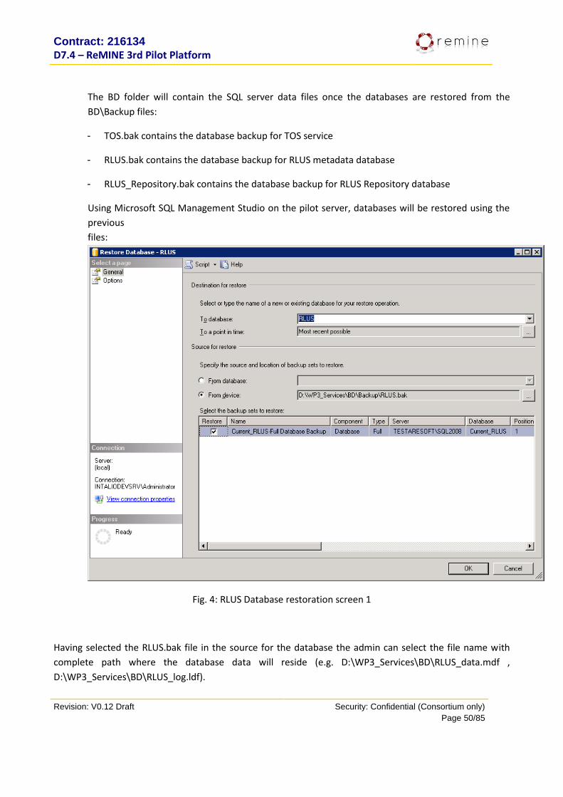
Contract: 216134
D7.4 – ReMINE 3rd Pilot Platform
Revision: V0.12 Draft Security: Confidential (Consortium only)
Page 50/85
The BD folder will contain the SQL server data files once the databases are restored from the
BD\Backup files:
- TOS.bak contains the database backup for TOS service
- RLUS.bak contains the database backup for RLUS metadata database
- RLUS_Repository.bak contains the database backup for RLUS Repository database
Using Microsoft SQL Management Studio on the pilot server, databases will be restored using the
previous
files:
Fig. 4: RLUS Database restoration screen 1
Having selected the RLUS.bak file in the source for the database the admin can select the file name with
complete path where the database data will reside (e.g. D:\WP3_Services\BD\RLUS_data.mdf ,
D:\WP3_Services\BD\RLUS_log.ldf).
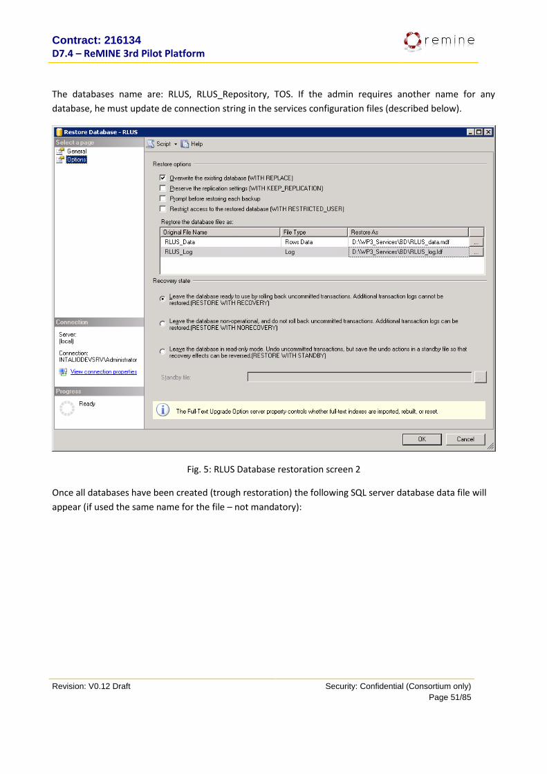
Contract: 216134
D7.4 – ReMINE 3rd Pilot Platform
Revision: V0.12 Draft Security: Confidential (Consortium only)
Page 51/85
The databases name are: RLUS, RLUS_Repository, TOS. If the admin requires another name for any
database, he must update de connection string in the services configuration files (described below).
Fig. 5: RLUS Database restoration screen 2
Once all databases have been created (trough restoration) the following SQL server database data file will
appear (if used the same name for the file – not mandatory):
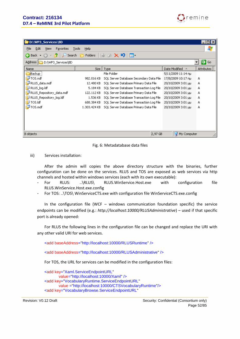
Contract: 216134
D7.4 – ReMINE 3rd Pilot Platform
Revision: V0.12 Draft Security: Confidential (Consortium only)
Page 52/85
Fig. 6: Metadatabase data files
iii) Services installation:
After the admin will copies the above directory structure with the binaries, further configuration can be done on the services. RLUS and TOS are exposed as web services via http channels and hosted within windows services (each with its own executable): - For RLUS: ..\RLUS\ RLUS.WinService.Host.exe with configuration file
RLUS.WinService.Host.exe.config - For TOS: ..\TOS\ WinServiceCTS.exe with configuration file WinServiceCTS.exe.config
In the configuration file (WCF – windows communication foundation specific) the service
endpoints can be modified (e.g.: http://localhost:10000/RLUSAdministrative) – used if that specific
port is already opened:
For RLUS the following lines in the configuration file can be changed and replace the URI with
any other valid URI for web services.
<add baseAddress="http://localhost:10000/RLUSRuntime" />
<add baseAddress="http://localhost:10000/RLUSAdministrative" />
For TOS, the URL for services can be modified in the configuration files:
<add key="Xaml.ServiceEndpointURL" value="http://localhost:10000/Xaml" />
<add key="VocabularyRuntime.ServiceEndpointURL" value ="http://localhost:10000/CTSVocabularyRuntime"/>
<add key="VocabularyBrowse.ServiceEndpointURL"
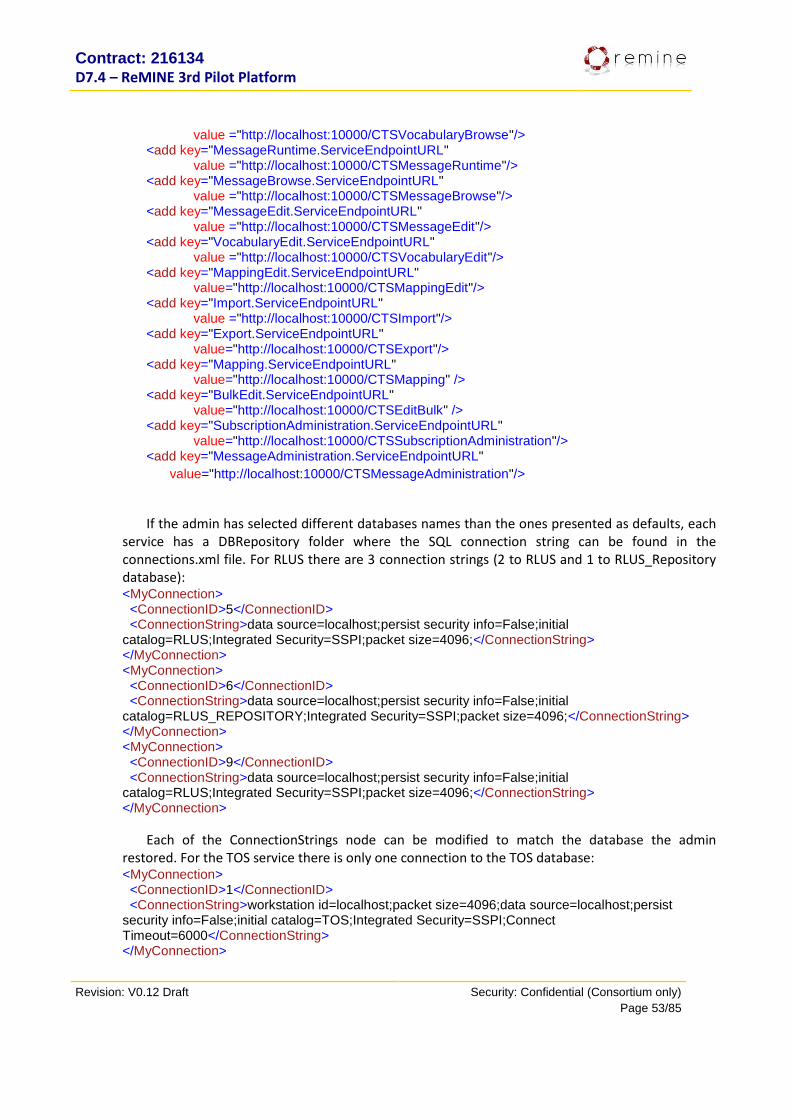
Contract: 216134
D7.4 – ReMINE 3rd Pilot Platform
Revision: V0.12 Draft Security: Confidential (Consortium only)
Page 53/85
value ="http://localhost:10000/CTSVocabularyBrowse"/> <add key="MessageRuntime.ServiceEndpointURL"
value ="http://localhost:10000/CTSMessageRuntime"/> <add key="MessageBrowse.ServiceEndpointURL"
value ="http://localhost:10000/CTSMessageBrowse"/> <add key="MessageEdit.ServiceEndpointURL"
value ="http://localhost:10000/CTSMessageEdit"/> <add key="VocabularyEdit.ServiceEndpointURL"
value ="http://localhost:10000/CTSVocabularyEdit"/> <add key="MappingEdit.ServiceEndpointURL"
value="http://localhost:10000/CTSMappingEdit"/> <add key="Import.ServiceEndpointURL"
value ="http://localhost:10000/CTSImport"/> <add key="Export.ServiceEndpointURL"
value="http://localhost:10000/CTSExport"/> <add key="Mapping.ServiceEndpointURL"
value="http://localhost:10000/CTSMapping" /> <add key="BulkEdit.ServiceEndpointURL"
value="http://localhost:10000/CTSEditBulk" /> <add key="SubscriptionAdministration.ServiceEndpointURL"
value="http://localhost:10000/CTSSubscriptionAdministration"/> <add key="MessageAdministration.ServiceEndpointURL"
value="http://localhost:10000/CTSMessageAdministration"/>
If the admin has selected different databases names than the ones presented as defaults, each
service has a DBRepository folder where the SQL connection string can be found in the connections.xml file. For RLUS there are 3 connection strings (2 to RLUS and 1 to RLUS_Repository database): <MyConnection> <ConnectionID>5</ConnectionID> <ConnectionString>data source=localhost;persist security info=False;initial catalog=RLUS;Integrated Security=SSPI;packet size=4096;</ConnectionString> </MyConnection> <MyConnection> <ConnectionID>6</ConnectionID> <ConnectionString>data source=localhost;persist security info=False;initial catalog=RLUS_REPOSITORY;Integrated Security=SSPI;packet size=4096;</ConnectionString> </MyConnection> <MyConnection> <ConnectionID>9</ConnectionID> <ConnectionString>data source=localhost;persist security info=False;initial catalog=RLUS;Integrated Security=SSPI;packet size=4096;</ConnectionString> </MyConnection>
Each of the ConnectionStrings node can be modified to match the database the admin restored. For the TOS service there is only one connection to the TOS database: <MyConnection> <ConnectionID>1</ConnectionID> <ConnectionString>workstation id=localhost;packet size=4096;data source=localhost;persist security info=False;initial catalog=TOS;Integrated Security=SSPI;Connect Timeout=6000</ConnectionString> </MyConnection>
Contract: 216134
D7.4 – ReMINE 3rd Pilot Platform
Revision: V0.12 Draft Security: Confidential (Consortium only)
Page 54/85
Next the admin has to create the windows services for RLUS and TOS using the “sc create” windows shell command. For example, having a user ‘user’ with password ‘password’ belonging to a windows domain ‘domain’, the batch looks like: >sc create ReMINE.RLUS binPath= "D:\WP3_Services\RLUS\ RLUS.WinService.Host.exe" start= auto
obj= user@domain password= password
>sc create ReMINE.TOS binPath= "D:\WP3_Services\TOS\ WinServiceCTS.exe " start= auto obj=
user@domain password= password
From the “Services” management console the admin can start the services:
Fig. 7: Metadatabase installed services
Once the services started, the admin can test the WSDL in any browser based on the URL given to
each service:
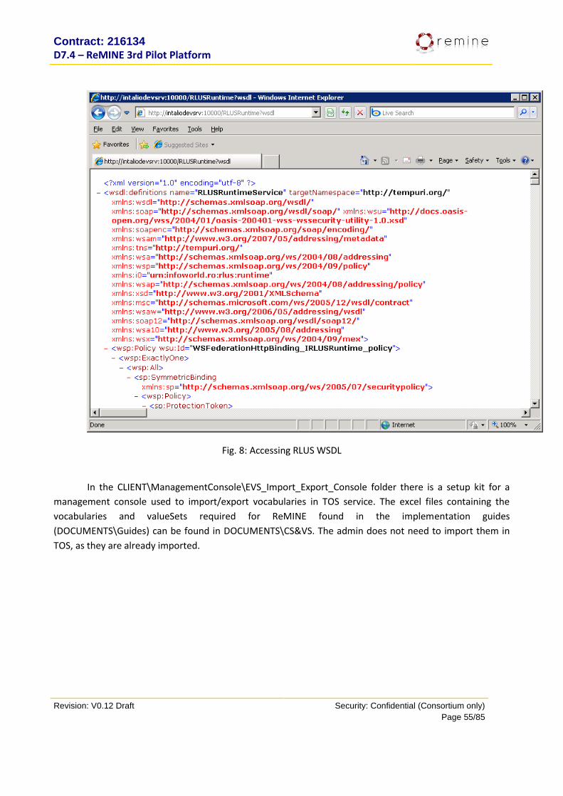
Contract: 216134
D7.4 – ReMINE 3rd Pilot Platform
Revision: V0.12 Draft Security: Confidential (Consortium only)
Page 55/85
Fig. 8: Accessing RLUS WSDL
In the CLIENT\ManagementConsole\EVS_Import_Export_Console folder there is a setup kit for a
management console used to import/export vocabularies in TOS service. The excel files containing the
vocabularies and valueSets required for ReMINE found in the implementation guides
(DOCUMENTS\Guides) can be found in DOCUMENTS\CS&VS. The admin does not need to import them in
TOS, as they are already imported.
Contract: 216134
D7.4 – ReMINE 3rd Pilot Platform
Revision: V0.12 Draft Security: Confidential (Consortium only)
Page 56/85
9. Data mining and Knowledge Extraction
9.1. Purpose The REMINE Data Mining Module is dedicated to the extraction of useful patterns from heterogeneous
clinical and other HIS (and beyond) data with the aid of semantic modeling. It is part of the core of the
system’s decision support process, analyzing the enriched/semantically structured data stored in the
REMINE DB (gathered from the complex patients’ clinical profiles, history and/or other information
available in the HIS) to discover patterns in the data which could help the Risk Manager to optimize the
associated risk management processes and policies. The output of the module, the discovered patterns
in the data is fed to the decision support logical reasoner, the Knowledge Inference System sub-module) for
their further elaboration.
The module’s primary functionality is to extract the most similar patient’s profiles from the integrated and normalized complex clinical data stored in the REMINE Repository. This is done in two steps: firstly the numerical and categorical data will be mined, and later the results will be fed to the semantic component (Knowledge Inference System) describing the risk assessments connected with specific medical symptoms.
9.2. 2nd Prototype Implementation Deliverable D3.7 – First revision of the data mining and knowledge extraction module addresses the
development process of both the data mining component, responsible for obtaining a descriptive model of
clinical data, and of the knowledge extraction module, which realizes the detection of risky situations based
on the clinical data model.
By using data mining scenarios, this deliverable models the situations in which data collected over time
can be of effective help in real-time risk identification and mitigation. The data mining and the knowledge
inference processes are presented by the application ontology, summarizing the data requirements and the
inter-relation between the two processes. The mining process is presented into details, outlining how the
data is saved into RLUS (with respect to semantic and syntactic integration issues), data acquisition from
RLUS into the general mining database, pre-processing steps including selection, cleaning, transformations
and loading into a scenario-specific data warehouse. The technologies chosen and the implementation
itself of the mining project are well documented and explained.
As regarding the tightly-related Knowledge Inference System, an Application Programming Interface is
proposed, comprising the service, data and fault contracts. The first prototype also details the Risk
Manager Interface that receives alerts from the Application Programming Interface and eventually delivers
the alerts to the clinicians.
9.3. 3rd Prototype Implementation Third revision of the data mining and knowledge extraction module addresses the implementation of
data mining component and the modelling of the selected mining scenarios, as also the development of the

Contract: 216134
D7.4 – ReMINE 3rd Pilot Platform
Revision: V0.12 Draft Security: Confidential (Consortium only)
Page 57/85
Knowledge Inference System and of the Risk Manager Interface, which consists in the risk manager
interface for the alerts produced by the Knowledge Inference System.
Deliverable D3.8 documents the development of the TRFT data mining scenarios, which aims at
providing expressive modelling of the historical data of patient administration and related MRSA infection
control activities. The laboratory results which confirms MRSA infections together with patient hospital and
ward admission are employed for identifying patterns that help predicting future risky situations for the
patients. The resulting mining models were used as the rule base for the Knowledge Inference System.
The Knowledge Inference System was implemented by relying on the well-defined foundation of
business rule engines. The deliverable specifies how the mining models are reused in this knowledge-based
inference engine for producing reliable risk pattern detection in new, real-time incoming data. The Risk
Manager Interface was also developed to deliver easy to use visual alerting capabilities to the risk manager
user.
9.4. Dependencies The data mining module depends only on the ReMINE Database from where the training and validating
subsets are selected. The CDAService ensures this process. There are two data mining tools used in ReMINE
Project, thus creating a dependency on these tools:
- SQL Server Analysis Services - WEKA
9.5. Interfaces with other components The Data Mining module provides knowledge representation models for the Knowledge Inference
System presented in the following chapter. The knowledge inference system directly accesses the data
mining results to see if any new data knowledge is available.
9.6. Resources Data mining is a computationally and storage intensive operation because it exhaustively searches
for recurring patterns in large datasets. Because mining is not an online operation, it works in periodic
batches; the use of a dedicated server is not required. The current pilot server specs satisfy the need for
this module.
9.7. Data/Messages The methodology used for data mining is Cross Industry Standard Process for Data Mining (CRISP-DM).
This is a data mining process model that describes commonly used approaches that expert data miners use
to tackle problems.
Data is sourced into the ReMINE Platform from HIS by using the H-ERP Bridge passes through the Data
Acquisition Layer and is stored into the RLUS database. However, the data from HIS must endure some
transformations to become conformant to the CDA standards enforced by the RLUS repository. Every data
mining scenario must define its own data requirements with respect to the HIS data contract and the CDA
document specifications.
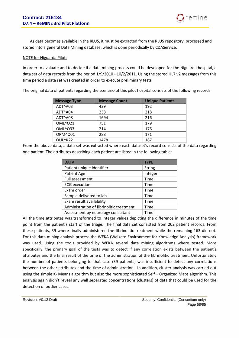
Contract: 216134
D7.4 – ReMINE 3rd Pilot Platform
Revision: V0.12 Draft Security: Confidential (Consortium only)
Page 58/85
As data becomes available in the RLUS, it must be extracted from the RLUS repository, processed and
stored into a general Data Mining database, which is done periodically by CDAService.
NOTE for Niguarda Pilot:
In order to evaluate and to decide if a data mining process could be developed for the Niguarda hospital, a
data set of data records from the period 1/9/2010 - 10/2/2011. Using the stored HL7 v2 messages from this
time period a data set was created in order to execute preliminary tests.
The original data of patients regarding the scenario of this pilot hospital consists of the following records:
Message Type Message Count Unique Patients
ADT^A03 439 192
ADT^A04 238 218
ADT^A08 1694 216
OML^O21 751 179
OML^O33 214 176
ORM^O01 288 171
OUL^R22 1478 187
From the above data, a data set was extracted where each dataset’s record consists of the data regarding
one patient. The attributes describing each patient are listed in the following table:
DATA TYPE
Patient unique identifier String
Patient Age Integer
Full assessment Time
ECG execution Time
Exam order Time
Sample delivered to lab Time
Exam result availability Time
Administration of fibrinolitic treatment Time
Assessment by neurology consultant Time
All the time attributes was transformed to integer values depicting the difference in minutes of the time
point from the patient’s start of the triage. The final data set consisted from 202 patient records. From
these patients, 39 where finally administered the fibrinolitic treatment while the remaining 163 did not.
For this data mining analysis process the WEKA (Waikato Environment for Knowledge Analysis) framework
was used. Using the tools provided by WEKA several data mining algorithms where tested. More
specifically, the primary goal of the tests was to detect if any correlation exists between the patient’s
attributes and the final result of the time of the administration of the fibrinolitic treatment. Unfortunately
the number of patients belonging to that case (39 patients) was insufficient to detect any correlations
between the other attributes and the time of administration. In addition, cluster analysis was carried out
using the simple K- Means algorithm but also the more sophisticated Self – Organized Maps algorithm. This
analysis again didn’t reveal any well separated concentrations (clusters) of data that could be used for the
detection of outlier cases.
Contract: 216134
D7.4 – ReMINE 3rd Pilot Platform
Revision: V0.12 Draft Security: Confidential (Consortium only)
Page 59/85
10. Guideline Execution Engine Notes to the reader:
The Guideline Execution Engine is described in D4.6, Version 2. This section takes a view on the
same topic from a different angle.
This section focuses on the What-If Tool. The execution of the MRSA Guideline to obtain daily
colour coding at TRFT is described elsewhere.
10.1. Purpose The purpose of the What-If Tool is to interactively explore the consequences of different input
combinations for treatment under the modeled guideline. It has two different uses:
The risk manager or other staff exploring risk situations related to that part of the care which is
described by the modeled guideline, may gain insights in the consequences of certain
constellations, i.e., combinations of patient conditions, which may relate to risks against patient
safety.
The domain experts can compare their expectations of the guideline execution with the output of
executing its model. Differences are commonly seen after initial modeling. In particular the
interpretation of missing data is rarely specified in guidelines and must be discussed on a per-case
basis.
10.2. 2nd Prototype Functionalities The What-If Tool was not scheduled to be part of the second prototype.
10.3. 3rd Prototype Functionalities At the 3rd review, the What-If Tool was not available. It was completed September 2011 when D4.6 was
submitted which fully describes its functionalities.
10.4. Dependencies The What-If Tool does not depend on other parts of the Remine system. It depends on the availability of a
web server and the Asbru Interpreter as described below.
10.5. Interfaces with other components The What-If Tool was implemented as a stand-alone prototype and does not interface with other parts of
the Remine system.
10.6. Resources The What-If Tool is implemented as a set of CGI scripts. It therefore runs on a web server. This web server
must have the programming language Perl installed, which is standard on Linux-style systems.

Contract: 216134
D7.4 – ReMINE 3rd Pilot Platform
Revision: V0.12 Draft Security: Confidential (Consortium only)
Page 60/85
The What-If Tool uses the Asbru Interpreter, which is enclosed with the What-If Tool.
10.7. Data/Messages Data is only passed between the different forms forming the tool. It is temporally stored locally when
starting the Asbru Interpreter, but not meant for reuse.
Messages are not exchanged with the rest of the system.
10.8. Installation instructions Copy the content of folder WHAT_IF_TOOL on the DVD to a newly created folder which is configured to
contain CGI scripts as described in the documentation of the web server in question.
Insure that the files with extension .cgi have execute permission set for everyone (world).
Append start.cgi to the URL of the folder containing the What-If Tool. E.g., if the folder is accessed as
http://www.ifs.tuwien.ac.at/cgiseyfang/remine/
then the What-If Tool is started at URL
http://www.ifs.tuwien.ac.at/cgiseyfang/remine/start.cgi .
11. Visualisation tool (Research Prototype Component -not integrated
with ReMINE platform) Note to the reader: The Visualisation tool is described in D4.8. This section takes a view on the same topic
from a different angle – we added cross references to reduce redundancy.
11.1. Purpose The purpose of the visualisation tool is to show patient data together with plans that were executed. These
plans represent care actions as modeled using Asbru.
11.2. 2nd Prototype Functionalities The intermediate state of work was described in an internal deliverable at M24. The actual implementation
was scheduled to be completed in M33.
11.3. 3rd Prototype Functionalities The final functionalities of the Visualisation Tool are described in Sections 8 and 9 of D4.8. They were
implemented before end of October 2010.
11.4. Dependencies The Visualisation Tool does not depend on other parts of the Remine system.
Contract: 216134
D7.4 – ReMINE 3rd Pilot Platform
Revision: V0.12 Draft Security: Confidential (Consortium only)
Page 61/85
11.5. Interfaces with other components The Visualisation Tool was implemented as a stand-alone research prototype and does not interface with
other parts of the Remine system.
11.6. Resources The Visualisation Tools is implemented as a JAR file. It requires the Java Runtime Engine, which is included
in standard Windows and Linux installations.
11.7. Data/Messages Data is not exchanged with other parts of the Remine system.
Local storage of data is described in Section 11 of D4.8.
11.8. Installation Instructions Copy the content of folder CARECRUISER on the DVD to a new folder "carecruiser".
In a DOS window, change to folder carecruiser and there, type:
carecruiser.jar examples\remineData\guidelines\BirthAsbruWithIntentions.xml
Alternatively, use another XML file that you created before.
We provide synthesised patient data for the BirthAsbruWithIntentions.xml guideline.
If you want to add (real or other synthesised) patient data to view in combination with one of the
guidelines, you need to edit
carecruiser\examples\remineData\guidelines\BirthAsbruWithIntentions.config
(or another guideline (+.config)) with a text editor of your choice.
In the first line of this file you need to add the name of the file with the additional patient data.
Please put the file with the patient data (a .txt file) into the directory
carecruiser\examples\remineData\patients.

Contract: 216134
D7.4 – ReMINE 3rd Pilot Platform
Revision: V0.12 Draft Security: Confidential (Consortium only)
Page 62/85
12. User Interface
12.1. Purpose The User Interface (GUI) allows the interaction between the system and the users (clinical staff and
administrators). Through the interface the user is able to insert data into the application, modify policies
(BRs), configure the system and check the different information and reports that ReMINE provides.
The framework looks different for each user depending on their roles. The interface automatically enables
and disables different components and features to ensure proper use of permissions for the different kind
of users. Although there is a unique workspace, the Graphical User Interface (GUI) can be divided in two
broad parts: Medical Process Interface (MPI) and Risk Manager Interface (RMI).
The Medical Process Interface (MPI) is intended for the clinical staff and it differs from one scenario to
another. Mainly the MPI use to be comprised of a tab for the patient admission; a different one for the
different clinical tasks to carry out for each patient; one more for the possibility of launching different
medical processes; and finally a tab for notifying the RAPS, showing all the alerts triggered for each patient.
There are special tabs for each pilot as in the case of Sacco scenario that presents a tab to provide the
patient risk level and a tab displaying a scheduler with the monitoring activity.
The Risk Manager Interface (RMI) is used for the administrator and manager users. This interface is the
same in the four different scenarios. It contains three tabs. The first one, Alert Management System (AMS)
tab, for managing all the settings and information related to Alert Management System. The second one,
Business Activity Monitoring (BAM) tab, provides the report created in run-time based on the information
obtained from the database. The Reports are created according to the Key Performance Indicators (KPIs)
defined for each scenario and building be means of different charts. These KPIs provide information about
the status of processes; medical information regarding the patients; and detailed statistics of the alerts
managed by the system. Finally, BPMS tab, allows the Risk Manager user to check the current situation of
the system regarding the execution and the performance of the processes (e.g. lifecycle status, process
flow, failures, etc.). Moreover, in case the user has the proper rights and permissions, the console allows
performing the following actions: start, stop, deploy and undeploy processes.
Figure 4. Graphical User Interface of Sacco scenario (MPI and RMI tabs)

Contract: 216134
D7.4 – ReMINE 3rd Pilot Platform
Revision: V0.12 Draft Security: Confidential (Consortium only)
Page 63/85
12.2. 2nd and 3rd Prototype Functionalities Comparison The 3rd Prototype functionality highly increases the user experience. The interaction between the interface
and the users is more friendly and predictable. High efforts for increasing the performance and the visual
aspect of the application have been carried out. The results are a faster and nice user interface and
consequently a higher acceptance and reliability in ReMINE application. In addition the interface
functionality has been enriched and increased. Mainly the enhancements can be listed as follow:
All ReMINE information is presented in one interface. All components were integrated in a common
GUI (processes, tasks, alerting, Business Activity monitoring etc.)
The interface automatically enables and disables different components based on user roles and
privileges
Friendly and intuitive interfaces
More information available for the users
Forms enhancement and optimization:
o New forms
o New data required based on medical staff requirements
o Barcode and RFID use
o Automatic input
o Checking input data in real-time for avoiding failures
o Immediate notifications for data input mistakes (message boxes)
o Translations
Risk level patient chart showing the risk for each patient based on medical conditions and hospital
status
Calendar with prediction of monitorings and virtual future protocol violationsprediction of the
patient status (mainly, the dilatation width) and the resources needed for each patient (staff,
devices and rooms)
Role -based access control to the application interface by using Light Directory Active Protocol
(LDAP).
Reports enhancement KPIs according to users

Contract: 216134
D7.4 – ReMINE 3rd Pilot Platform
Revision: V0.12 Draft Security: Confidential (Consortium only)
Page 64/85
Figure 5. Patient Risk Level tab
12.3. Dependencies The GUI is directly interconnected with the processes, the internal database modules and with the security
layer for the whole platform. The GUI is able launch different processes and also to interact with the
process trough dedicated forms. On the other hand the connection between the GUI and the database
allows showing relevant information to the end-user, among them reports and performance statics.
Due to the environment within the project is developed and the information managed, the security
implemented for the data handled by the system and the communications is a critical task. The data
collected in the hospital for each patient should be confidential and private, hence the security to protect a
potential modification or illegal access to the information or any violation of the patient privacy was one of
the main goals of the project. Also the communications among all the subsystems and the different access
points to the scenarios have to be secured, as they can present several security problems. As the
architecture of the system is service-oriented (SOA) the security over the communications presents an
important issue.
The REMINE pilot server is placed within the confines of the local HIS Firewall. The local HIS Firewall and the
use of specific user access list (with the associated credentials) are the main security measures for avoiding
any malicious access to the platform. Also the access to the different parts is restricted depending on the
user roles.
The security is implemented under a role based interface and managed by means of LDAP, taking in
account the possibilities of Intalio server security. In other words, the different users of the system need to
authenticate and obtain rights and permissions for the different resources and task. It is controlled by the
security system, denying unauthorized access depending on the roles of the users assigned by the manager
of the system.
The ReMINE login makes use of RBAC. Role-based access control (RBAC) is an approach to restricting
system access to authorized users. The permissions to perform certain operations are assigned to specific
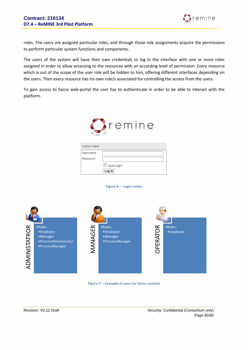
Contract: 216134
D7.4 – ReMINE 3rd Pilot Platform
Revision: V0.12 Draft Security: Confidential (Consortium only)
Page 65/85
roles. The users are assigned particular roles, and through those role assignments acquire the permissions
to perform particular system functions and components.
The users of the system will have their own credentials to log in the interface with one or more roles
assigned in order to allow accessing to the resources with an according level of permission. Every resource
which is out of the scope of the user role will be hidden to him, offering different interfaces depending on
the users. Then every resource has his own role/s associated for controlling the access from the users.
To gain access to Sacco web-portal the user has to authenticate in order to be able to interact with the
platform.
Figure 6: – Login screen
Figure 7: – Example of users for Sacco scenario
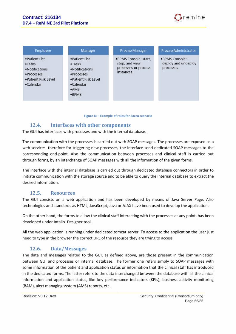
Contract: 216134
D7.4 – ReMINE 3rd Pilot Platform
Revision: V0.12 Draft Security: Confidential (Consortium only)
Page 66/85
Figure 8: – Example of roles for Sacco scenario
12.4. Interfaces with other components The GUI has interfaces with processes and with the internal database.
The communication with the processes is carried out with SOAP messages. The processes are exposed as a
web services, therefore for triggering new processes, the interface send dedicated SOAP messages to the
corresponding end-point. Also the communication between processes and clinical staff is carried out
through forms, by an interchange of SOAP messages with all the information of the given forms.
The interface with the internal database is carried out through dedicated database connectors in order to
initiate communication with the storage source and to be able to query the internal database to extract the
desired information.
12.5. Resources The GUI consists on a web application and has been developed by means of Java Server Page. Also
technologies and standards as HTML, JavaScript, Java or AJAX have been used to develop the application.
On the other hand, the forms to allow the clinical staff interacting with the processes at any point, has been
developed under Intalio|Designer tool.
All the web application is running under dedicated tomcat server. To access to the application the user just
need to type in the browser the correct URL of the resource they are trying to access.
12.6. Data/Messages The data and messages related to the GUI, as defined above, are those present in the communication
between GUI and processes or internal database. The former one refers simply to SOAP messages with
some information of the patient and application status or information that the clinical staff has introduced
in the dedicated forms. The latter refers to the data interchanged between the database with all the clinical
information and application status, like key performance indicators (KPIs), business activity monitoring
(BAM), alert managing system (AMS) reports, etc.
Contract: 216134
D7.4 – ReMINE 3rd Pilot Platform
Revision: V0.12 Draft Security: Confidential (Consortium only)
Page 67/85
12.7. Installation instructions This module does not need a particular procedure for its installation. By following the installation
instructions explained in section 7.7 for the installation of the server is enough. The GUI has been pre-
installed as a web application in the dedicated tomcat server, so it is no needed to take further actions.
13. Alerting System
12.8. Purpose The alerting system intends to enrich Remine with the ability to send Alerts through different channels,
namely: SMS, Email. As an administrative tool, the Alert system also provides a connector that stores an
“alert” into the database allowing a log to be stored. The system is composed of three main entities: alert,
along with the intended delivery channels, and alert instance. An alert might have one, or more, delivery
channels configured, which will be used, by the alerting system, when the alert is triggered when an alert is
created. Currently, the alerting system supports three different channels:
1. Log message into database, used mainly for administrative purposes and where the alert will not
require to be acknowledged.
2. SMS, where an alert message will be delivered to the mobile phone configured in the recipients
profile. The acknowledgment of these alerts will be received through the same channel, meaning
that the recipient shall reply to the system with an SMS.
3. Email, where an alert message will be delivered to the email configured in the recipients profile. In
this case the recipient will acknowledge the alert by following the instructions in the email and
accessing the provided URL.
In send email and/or SMS actions, there must be defined one or more recipients, belonging to hospital
staff.
The system was entirely implemented in Java and is divided into two deploys, one to be deployed in a
Tomcat webapp folder, and the other on Axis2 services folder, these components and how to configure and
setup them will be described in a section below.
The main interface is a web application, named RemAlerting, which combines two servlets, RemAlerting
and SMSResponse. RemAlerting servlet contains the Risk Manager Interface, while the SMSResponse
contains a web form that is used by the contracted SMS hosting Service to notify the Remine alerting
system of any SMS Acknowledgment.
Finally, the Axis2 service, named RemineNotifierWS, exposes a web service, available to the other Remine
modules, and that allows them to initiate and cancel alerts.
Contract: 216134
D7.4 – ReMINE 3rd Pilot Platform
Revision: V0.12 Draft Security: Confidential (Consortium only)
Page 68/85
13.2. 2nd Prototype Functionalities The Alert server on the second Prototype had a stable interface with the remaining modules and presented
to the system the basic functionalities to send an Alert to the configured recipients. In a brief description,
on this release the system presented the following functionalities:
Alert Sending through Email and SMS
Alert escalation, by sending a new alert to the next recipient on the alerts recipients list.
Risk Manager Interface to manage Alert configurations and Alert Recipients information.
13.3. 3rd Prototype Functionalities The Alert Module was slightly improved on the third Remine Prototype, the major functionalities of the
system were already in place, but the users requests have showed the need to change the system a bit. So,
the third instalment included a few bug fixes and the following new functionalities:
Alert sending to a database log, mainly used has a possible log file.
Programmatically Cancel, or Stop, Alerts. This new functionality allowed the “client” modules to
forcibly cancel an alert through the Alerts Web Methods. This also forced a change on second
instalment interface.
13.4. Dependencies The alerting system requires the existence of an email server, along with an email account to be able to
send alerts through this channel. Additionally, it also requires a SMS hosting account in order to be able to
send and receive acknowledgements through this channel. These information must be configured in the
“application.properties” section (detailed instructions on how to find and configure each module are
presented in detail under section 13.6).
13.5. Interfaces with other components The alerting system is mainly used by Intalio in order to alert hospital staff by SMS and/or Email, and the
chosen interface was a web service, making it a decoupled module. The decoupling allows other modules
to use of the alerting system, and will also allow to scale the system performance horizontally since it can be
installed in a different machine from the rest of the application and accessed remotely.
The web service provides two methods to be used by the other modules:
startAlert: which triggers an alert and execute his actions.
stopAlert: cancel the execution of pending actions.
Contract: 216134
D7.4 – ReMINE 3rd Pilot Platform
Revision: V0.12 Draft Security: Confidential (Consortium only)
Page 69/85
It also provides an HTTP Form that should be used by SMS host service to notify alerting system of reply
messages. This simplified, and more limited, interface was required, since the chosen SMS provided were
not able to use a Web Service interface.
13.6. Resources Alerting System uses properties files to store its configuration and enable the system administrator to easily
change and configure the entire module by editing a text files. The RemAlerting application allows the
configuration of database, while the RemineNotifierWS allows the configuration of SMS hosting service and
Email provider.
The RemAlerting application contains an application.properties file under “WebContent/WEB-INF/classes/”
folder. The table below presents the properties used in this file.
Propriety Description Example
db.url The connection string to database jdbc:mysql://neomark.link.pt/remine
db.user The username to get access to database remine
db.password The password to get access to database PasswordToBeChanged
Table 1 – RemAlerting application properties
The RemineNotifierWS deploy contains a similar application.properties file under “resources/META-INF/”
folder, and contains the follow properties:
Propriety Description Example
smsservice.address The endpoint address to SMS hosting
web service
http://ws.smshosting.it/smsWS/se
rvices/smsService
smsservice.user The username to log-in into SMS hosting
service
Remine
smsservice.password The password to log-in into SMS hosting
service
passwordToBeChanged
smsservice.originator The SMS hosting service phone number,
used to acknowledge the Alerts sent by
SMS.
00393470000000
smsservice.hostemailaddress The address to where SMS provider will
forward any SMS reply.
192.168.10.1
smsservice.hostemailport The port on the previous address that 80

Contract: 216134
D7.4 – ReMINE 3rd Pilot Platform
Revision: V0.12 Draft Security: Confidential (Consortium only)
Page 70/85
the SMS provider will try to reach.
smsservice.reply_message Fixed text to explain the reply
mechanism in the SMS message
Please reply with the follow
message
smsservice.key The keyword that the recipient shall use
in the reply to an alert.
Remine
mail.subject The email subject [ALERT] Remine Message Alert
mail.mail The email from where emails are sent [email protected]
mail.smtp.host The SMTP server name or ip mail.remine.eu
mail.smtp.port The port where SMTP server is listening 25
mail.smtp.user The username to log-in into SMTP server Remine
mail.smtp.pwd The password to log-in into SMTP server passwordToBeChanged
mail.smtp.ssl Specify if connection is secured using SSL True
mail.smtp.auth Specify if SMTP server requires
authentication
True
Table 2 – RemineNotifierWS application properties
13.7. Data/Messages The follow image (Illustration 1) presents the Alerting system model, which is currently persisted in a
MySQL database, but could easily be changed to other database engine.

Contract: 216134
D7.4 – ReMINE 3rd Pilot Platform
Revision: V0.12 Draft Security: Confidential (Consortium only)
Page 71/85
Illustration 1 – Alerting System Model
The alerting system receives messages from other Remine modules, over the published interface named
RemineNotifierWS, and also from SMS hosting Service, over SMSResponse Servlet. The Illustration 2
presents a diagram with the input and output messages for the Alerting System.
Illustration 2 – Alerting System messages flow

Contract: 216134
D7.4 – ReMINE 3rd Pilot Platform
Revision: V0.12 Draft Security: Confidential (Consortium only)
Page 72/85
The alerting system receives requests to start and stop alerts and send notifications to hospital staff from
Email provider and a SMS Hosting Service, in case of an SMS reply message the system is notified from
SMSResponse servlet.
The RemineNotifierWS interface can be seen in Table 3.
Method Method’s Arguments Explanation
startAlert
Create an alert’s instance, which result in the
execution of the actions associated to the alert
(String) name The name of the alert that should be sent.
(String) reason
The reason to send the alert, this will make part of
the text send by SMS, Email or write into the
database.
[Return Value] int
The method returns the ID for the alert created,
which can then be used to cancel/stop it. If an error
occurs, then the method returns the value -1.
stopAlert Cancel the execution of an alert instance.
(int) alertId The alert’s instance identifier that wants to cancel.
[Return Value] boolean
The return value is true case everything goes right,
and false otherwise
Table 3 – RemineNotifierWS interface
The SMSResponse Servlet is a single http form, with the follow interface:
Parameter Description
testo The SMS text
Number The phone number that sent the message
Table 4 – SMSResponse interface
13.8. Installation instructions The alert system is divided into two packages 'deploy', RemAlerting and RemineNotifierWS. The
RemAlerting package holds two servlets, RemAlerting and SMSResponse. The servlet RemAlerting contains
the implementation of the Risk Manage Web Interface while SMSResponse is a web form that functions as
the interface that allows the SMS hosting service to notify the alerting system of replies coming from

Contract: 216134
D7.4 – ReMINE 3rd Pilot Platform
Revision: V0.12 Draft Security: Confidential (Consortium only)
Page 73/85
hospital staff. The RemineNotifierWS package holds a web service that provides an interface to other
Remine modules initiate and cancel alerts.
The alert system must be accessible to the SMS Provider that it’s in the internet, outside the security zone
of the application, so as a security precaution, the system architecture will deploy the servlet SMSResponse
in the DMZ and the remaining application on the intranet, inaccessible by the outside.
The following image presents a suggested architecture, however some of the system functions may all be
aggregated in the same machine instead of being divided as shown in the illustration (eg: email server,
database server and web server may all reside in a single machine). It’s also possible to reduce physical
architecture complexity by using a reverse proxy, and so in that case the reverse proxy would take the
responsibility of filtering all internet requests and redirect those to the internal server where the
SMSResponse servelet would be installed.
Illustration 3 – Alerting system physical architecture
The Alert system module, requires, and assumes, that the following software and service are already
installed:
Apache HTTP Server
Tomcat
Apache Axis2/Java version
MySQL Server
Email Server
The system administrator should also have the follow information to correctly configure the application:
MySQL Database connection string
MySQL user login

Contract: 216134
D7.4 – ReMINE 3rd Pilot Platform
Revision: V0.12 Draft Security: Confidential (Consortium only)
Page 74/85
SMS Hosting Service endpoint
SMS Hosting Service user login
Email Server Ip/Name
Email Server Port
Email Provider user login (if required)
NOTE: We assume that the MySQL has a database with the schema presented in Illustration 1.
Next we present the steps to install RemineNotifierWS:
1. Open RemineNotifierWS.aar file with a compression program like 7zip or WinRar;
2. Go to META-INF folder;
3. Open application.properties file with a text editor;
4. Fill the file with the help of Table 2 that you can find in this document (page 70);
5. Save the application.properties file and close RemineNotifierWS.aar file;
6. Copy the resulting RemineNotifierWS.aar file to %TOMCAT-INSTALLATION-FOLDER%\webapps\axis2\WEB-INF\services directory;
7. Restart Tomcat;
8. Open a browser and go to http://httpserver/axis2/services/listServices, you should see RemineNotifierWS in the available services’s list.
Step-by-step installation of RemAlerting (intranet and DMZ):
1. Go to RemAlerting\WebContent\WEB-INF\classes folder;
2. Open application.properties file with a text editor;
3. Fill the file with the help of Table 1 that you can find in this document (page 69);
4. Copy RemAlerting folder to %TOMCAT-INSTALLATION-FOLDER%\webapps directory;
5. Restart Tomcat;
6. (Only needed for a DMZ installation) Disable RemAlerting servlet
6.1. Go to RemAlerting\WebContent\WEB-INF\ folder
6.2. Open web.xml and comment the follow block:
<servlet-mapping>
<servlet-name>remalerting</servlet-name>
<url-pattern>*.html</url-pattern>
</servlet-mapping>
6.3. Test application
6.3.1. (Intranet) Open a browser and go to http://httpserver/RemAlerting you should see the alerting system back office.
6.3.2. (DMZ) Open a browser and go to http://httpserver/RemAlerting/SMSResponse it should give you a java error
6.3.3. (DMZ) Open a browser and go to http://httpserver/RemAlerting it should give you an HTTP 404 message

Contract: 216134
D7.4 – ReMINE 3rd Pilot Platform
Revision: V0.12 Draft Security: Confidential (Consortium only)
Page 75/85
14. Rules Engine
14.1. Purpose This sub-model provides recommendations or solutions for driving the flow of a particular situation in order
to control and influence the behavior of the business within the healthcare service. The business rules aims
to establish the guidelines, defining policies and medical protocols, requirements and conditional
statements.
ReMINE is a rule-based application, which allow to the clinical responsible of the scenario to drive the
scenario and the clinical pathway based on the medical protocols and their own policy.
Figure 9: Architecture of a rule-based application system.
14.2. 2nd Prototype Functionalities The 2nd Prototype had a reduced set of business rules (BRs) integrated. Thus it had less flexibility to control
the clinical pathway. In addition less notification messages and alerts due to protocol violation were
managed and sent to the clinical staff.
14.3. 3rd Prototype Functionalities The 3rd Prototype has added a new set of business rules, improving and optimizing the clinical pathway.
Furthermore the module for managing predictive business rules has been developed. As the reader may
know by previous deliverables, the BRs can be divided in two groups (just for Sacco scenario):
Real Time Business Rules: support real time management of a contingent risky situation for
a specific patient, thus their effect on patient safety is immediate.
Predictive Business Rules: detect a potential future risky situation for a (group of)
patient(s), thus their effect on patient safety is in the future. In other words, RAPS
prediction, detection and control.
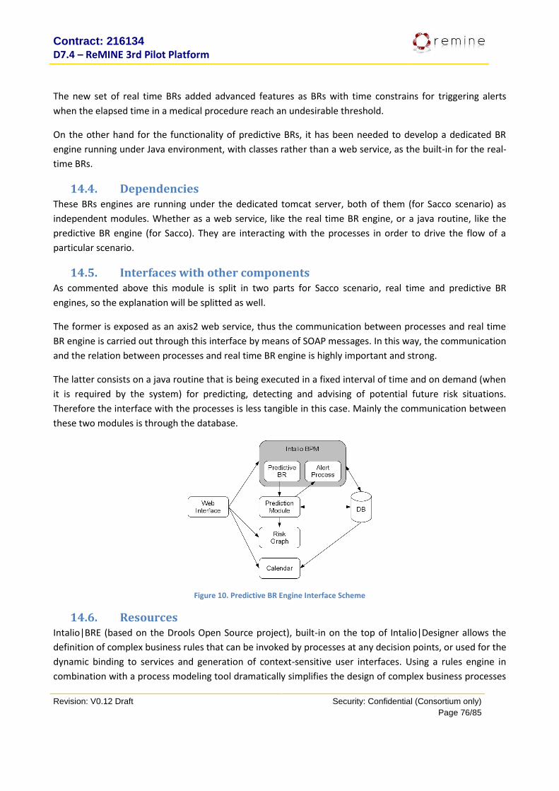
Contract: 216134
D7.4 – ReMINE 3rd Pilot Platform
Revision: V0.12 Draft Security: Confidential (Consortium only)
Page 76/85
The new set of real time BRs added advanced features as BRs with time constrains for triggering alerts
when the elapsed time in a medical procedure reach an undesirable threshold.
On the other hand for the functionality of predictive BRs, it has been needed to develop a dedicated BR
engine running under Java environment, with classes rather than a web service, as the built-in for the real-
time BRs.
14.4. Dependencies These BRs engines are running under the dedicated tomcat server, both of them (for Sacco scenario) as
independent modules. Whether as a web service, like the real time BR engine, or a java routine, like the
predictive BR engine (for Sacco). They are interacting with the processes in order to drive the flow of a
particular scenario.
14.5. Interfaces with other components As commented above this module is split in two parts for Sacco scenario, real time and predictive BR
engines, so the explanation will be splitted as well.
The former is exposed as an axis2 web service, thus the communication between processes and real time
BR engine is carried out through this interface by means of SOAP messages. In this way, the communication
and the relation between processes and real time BR engine is highly important and strong.
The latter consists on a java routine that is being executed in a fixed interval of time and on demand (when
it is required by the system) for predicting, detecting and advising of potential future risk situations.
Therefore the interface with the processes is less tangible in this case. Mainly the communication between
these two modules is through the database.
Figure 10. Predictive BR Engine Interface Scheme
14.6. Resources Intalio|BRE (based on the Drools Open Source project), built-in on the top of Intalio|Designer allows the
definition of complex business rules that can be invoked by processes at any decision points, or used for the
dynamic binding to services and generation of context-sensitive user interfaces. Using a rules engine in
combination with a process modeling tool dramatically simplifies the design of complex business processes
Contract: 216134
D7.4 – ReMINE 3rd Pilot Platform
Revision: V0.12 Draft Security: Confidential (Consortium only)
Page 77/85
that require many variations across multiple dimensions, such changes in policies or circumstances in the
pilots. In other words real time BRs are developed under Intalio|Designer and developed in the server at
the same time as the process development. In this development, the business rules engine is exposed as an
axis2 web service in the dedicated tomcat server to be accessed by the ReMINE processes.
The predictive BRs (Sacco scenario) are developed in Java code. The routine is running in the dedicated
tomcat server and exposed as java classes.
14.7. Data/Messages The data and messages interchange between real time BR engine service and the processes are carried out
through SOAP messages, as the former one is exposed as axis2 web service to handle the communications
between these two modules. The SOAP request is sent from the processes, attaching the required
information, according to the BR consult. The BR engine by looking up in the BR table, sends the response
to the processes with the corresponding results.
Basically the structure of the business rule system consist of two inputs (facts and rules) that are applied to
the business rules engine in order to produce the results required. The rules are the policy stated in BR
tables and defined by the clinical staff. The facts are sent by the processes depending on the status of the
clinical procedure. The output or results are the information returned by the BR engine service. More
specifically, the three parts of the BR system are:
Facts: medical information
Rules: guidelines based on clinical protocols, defining:
• Clinical pathway
• Protocol constrains
• Time constrains
Results:
• Process flow, i.e. clinical pathway
• Messages and alerts when violation of protocol occurs
• Messages and alerts when violation of protocol have been foreseen by the system
• Current and future patient risks and predictions
On the other hand, the predictive BR engine (developed for Sacco scenario) is exposed as java classes, thus
the calls to this engine are through the developed java routine. The information of the patients and
contextual information of the hospital is extracted from the internal database where the processes have
stored all the required information for such module.
14.8. Installation instructions This module does not need a particular procedure for its installation. By following the installation
instructions explained in section 7.7 for the installation of the processes is enough. The real time BR engine
is automatically deployed into the server as axis2 services just by deploying the different processes. Also
the predictive BR engine has been pre-installed in the dedicated tomcat server for Sacco scenario, so it is no
needed to take further actions.
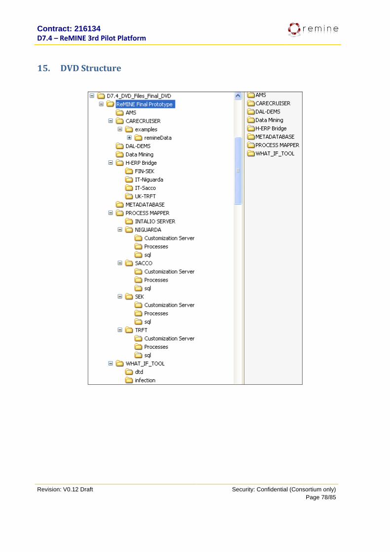
Contract: 216134
D7.4 – ReMINE 3rd Pilot Platform
Revision: V0.12 Draft Security: Confidential (Consortium only)
Page 78/85
15. DVD Structure
Contract: 216134
D7.4 – ReMINE 3rd Pilot Platform
Revision: V0.12 Draft Security: Confidential (Consortium only)
Page 79/85
16. Annex
16.1. SLA No modifications in the RFP. What has been described in D7.3 is still up to date.
16.2. Pilots Remote Access (added the other 2 pilots SEK and TRFT)
16.2.1. Niguarda Hospital
Architectural description
The VPN Service available at Niguarda is based on two different technologies: VPN IPSec and VPN SSL.
- VPN IPSec is a VPN which links together two networks through a tunnel over the Internet. This kind of protocol requires that the client machine, which accesses the local network from the outside, has a VPN client installed in order to enable the use of an IP address dedicated to remote connection. In order to access a VPN IPSec network, it is mandatory to manually specify an IP address and the settings related to a digital certificate. Moreover, it may not be possible to set a VPN connection due to the features of the network where the client is placed. For these reasons, it is preferred to provide the service by using the VPN SSL technology, in order to make easier, safer and more functional the connection for external users.
- VPN SSL does not require to install applications or to set particular features on the client machine. The SSL protocol (Secure Socket Layer) is used to grant protection over communication between the Web server and the client PC at application level. Since most web browsers support SSL, this protocol turns out to be simple to be implemented even on a wide number of PCs. Network security for VPN SSL moves from network and operating system level to application level, by applying common network protocols applied over the Internet, without having to implement any relevant modification on the client system. User authentication is prevalently based on token SMS, which requires to enter domain username and password followed by the access code received with a sms sent on user’s personal mobile phone. It is even possible to ask for a token hardware to be used as an alternative to the sms code.
Based on the previous descriptions, it has been chosen to prefer VPN SSL, while VPN IPSec has been left
just to marginal features. By now, VPN IPSec access is available just to authorized users from a proper
service page, after VPN SSL authentication.
VPN SSL of Azienda Ospedaliera Niguarda Ca’ Granda is based on a private application realized by Juniper,
whose use is allowed to 350 simultaneous users.

Contract: 216134
D7.4 – ReMINE 3rd Pilot Platform
Revision: V0.12 Draft Security: Confidential (Consortium only)
Page 80/85
VPN Access and authentication
The user opens one of the compatible Web browsers, Internet Explorer ver. 6 and 7 or Opera ver.
9.26, and access the home page at the following address: http://accessoweb.ospedaleniguarda.it/Example,
where “Example” will be substituted by the name of the authentication profile set for the external user.
Then he fills in the first authentication field by typing Domain username and password, which are the same
already present in Active Directory (Figure 11).
Figure 11 – Domain authentication
After the first authentication, a new form has to be filled in with the code received through SMS (Figure
12).
Figure 12 – SMS code authentication
If a token hardware has been required, the second form will ask to insert the PIN code shown in the Token
display (Figure 13).
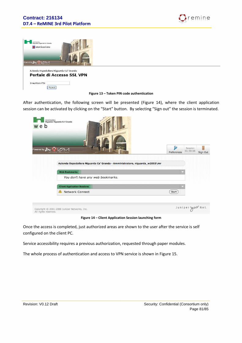
Contract: 216134
D7.4 – ReMINE 3rd Pilot Platform
Revision: V0.12 Draft Security: Confidential (Consortium only)
Page 81/85
Figure 13 – Token PIN code authentication
After authentication, the following screen will be presented (Figure 14), where the client application
session can be activated by clicking on the “Start” button. By selecting “Sign out” the session is terminated.
Figure 14 – Client Application Session launching form
Once the access is completed, just authorized areas are shown to the user after the service is self
configured on the client PC.
Service accessibility requires a previous authorization, requested through paper modules.
The whole process of authentication and access to VPN service is shown in Figure 15.

Contract: 216134
D7.4 – ReMINE 3rd Pilot Platform
Revision: V0.12 Draft Security: Confidential (Consortium only)
Page 82/85
Paper module to ask for VPN authorization
User
https://accessoweb.ospedaleniguarda.it/Example
SYSTEM
Figure 15 – Authentication and access procedure to VPN service
16.2.2. Sacco Hospital Remote access to Sacco Hospital VPN is based on Netasq IPSec .
Client installation and Ospedale Sacco VPN LAN access instructions:
Install the netasq IPSec client, downloadable from http://vpn.netasq.com/, using the serial number
provided by Ospedale Sacco
After successful installation, open the VPN client from desktop icon. The online activation process will
starts. To accomplish this step is necessary to use the s/n as mentioned before while having an active
online internet connection.
After successful online activation, opening client will appear the following mask
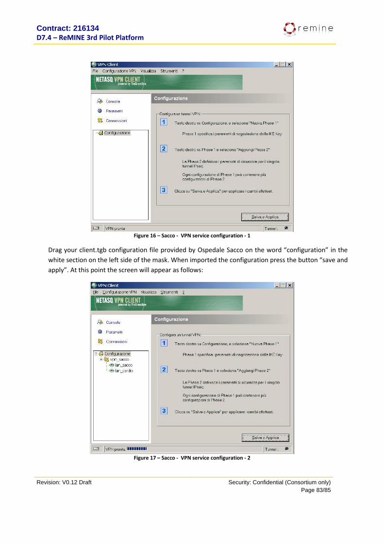
Contract: 216134
D7.4 – ReMINE 3rd Pilot Platform
Revision: V0.12 Draft Security: Confidential (Consortium only)
Page 83/85
Figure 16 – Sacco - VPN service configuration - 1
Drag your client.tgb configuration file provided by Ospedale Sacco on the word “configuration” in the
white section on the left side of the mask. When imported the configuration press the button “save and
apply”. At this point the screen will appear as follows:
Figure 17 – Sacco - VPN service configuration - 2

Contract: 216134
D7.4 – ReMINE 3rd Pilot Platform
Revision: V0.12 Draft Security: Confidential (Consortium only)
Page 84/85
Close the configuration panel. You can now open the vpn tunnel towards Ospedale Sacco pressing the
right mouse key on the tray bar icon and selecting “open tunnel lan_sacco”
Screen will changes as follows:
The IPSec tunnel is open and the connection to the Ospedale Sacco LAN is now active.
The communication from IPSec VPN client to lan sacco need the following port and protocols to be opened
and active both sides: 500 UDP, protocol ESP, 4500 UDP
After successfully opening tunnel it’s possible to test communication pinging the address: 10.1.10.254
16.2.3. TRFT Hospital (UK) The user opens the Web browsers and access the home page at the following address:
https://secure.therotherhamft.nhs.uk/dana-na/auth/url_0/welcome.cgi.
Then he fills in the first authentication field by typing the company username (e.g. TP-NOEMALIFE, TP-
INDRA,….) and password made by the Domain password + a PIN sent by sms.
Figure 18 – VPN authentication
After the authentication, a new form pops up where the only server available for the user is the ReMINE
server. The link starts a Remote desktop control session. In the same time a new password is sent via sms
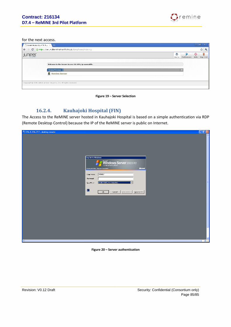
Contract: 216134
D7.4 – ReMINE 3rd Pilot Platform
Revision: V0.12 Draft Security: Confidential (Consortium only)
Page 85/85
for the next access.
Figure 19 – Server Selection
16.2.4. Kauhajoki Hospital (FIN) The Access to the ReMINE server hosted in Kauhajoki Hospital is based on a simple authentication via RDP
(Remote Desktop Control) because the IP of the ReMINE server is public on Internet.
Figure 20 – Server authentication