remedial action work plan - new york state department of
TRANSCRIPT

REMEDIAL ACTION WORK PLAN
FOR
UST AREA CHEMICAL OXIDATION
ESSEX JAMESTOWN SITE
129 HOPKINS AVENUE
JAMESTOWN, NY
NYDEC Site ID No. 9-07-015
Prepared for:
ESSEX SPECIALTY PRODUCTS INC.
(A FORMER SUBSIDIARY OF THE DOW CHEMICAL COMPANY)
Prepared by:
URS CORPORATION
PITTSBURGH, PA
URS Project No. 41568097
May, 2011

TABLE OF CONTENTS
Page No.
1.0 Background .................................................................................................... 1-1
1.1 Purpose .................................................................................................. 1-1
1.2 Remedial Action Objectives ................................................................... 1-1
2.0 SITE HISTORY AND DESCRIPTION .......................................................... 2-1
2.1 Site History ............................................................................................ 2-1
2.2 Site Description...................................................................................... 2-3
2.3 Site Geology .......................................................................................... 2-3
2.4 Hydrogeology ........................................................................................ 2-4
3.0 SUMMARY OF SITE CONTAMINATION ................................................... 3-1
3.1 Soil Analytical Results ........................................................................... 3-1
3.2 Groundwater Analytical Results ............................................................. 3-2
4.0 PROPOSED REMEDIAL ACTION ............................................................... 4-1
4.1 General .................................................................................................. 4-1
4.2 Chemical Oxidation Treatability Study................................................... 4-2
4.2.1 Test Sample Baseline Characterization.................................... 4-2
4.2.2 Desorption Testing.................................................................. 4-3
4.2.3 Stirred Reactor Batch Testing.................................................. 4-3

4.2.4 Soil Column Testing ............................................................... 4-4
4.2.5 Conclusion.............................................................................. 4-5
4.3 Proposed Remedial Action ..................................................................... 4-5
5.0 REMEDIAL ACTION SCOPE OF WORK..................................................... 5-6
5.1 Stormwater Drainage System Modifications ........................................... 5-6
5.1.1 Drywell Closure...................................................................... 5-6
5.1.2 New Stormwater Drainage System.......................................... 5-7
5.2 Permits................................................................................................... 5-7
5.3 Construction Health and Safety Plan....................................................... 5-8
5.4 Mobilization & Site Preparation ............................................................. 5-9
5.4.1 Temporary Facilities ............................................................. 5-10
5.4.1.1 Employee Parking..........................................................5-10
5.4.1.2 Availability and Use of Utility Services .........................5-11
5.4.1.3 Storage Areas.................................................................5-11
5.4.2 Protection and Maintenance of Traffic................................... 5-11
5.4.3 Security Provisions ............................................................... 5-11
5.4.4 Erosion and Sediment Control............................................... 5-12
5.4.5 Equipment Decontamination ................................................. 5-12
5.4.6 Spill and Discharge Control .................................................. 5-12
5.4.7 Survey and Work Stake-out................................................... 5-13

5.5 Baseline Groundwater Sampling........................................................... 5-14
5.6 Pre-Work Injection and Infiltration Field Tests ..................................... 5-14
5.6.1 Injection Test ........................................................................ 5-14
5.6.2 Infiltration Test ..................................................................... 5-15
5.7 Chemical Oxidation Implementation Plan............................................. 5-16
5.7.1 InSitu Treatment Design Guidelines...................................... 5-17
5.7.1.1 Treatment Zone Pore Volume ........................................5-17
5.7.1.2 Injection Pressure Guideline...........................................5-18
5.7.1.3 Hydraulic Acceptance Rate ............................................5-19
5.7.1.4 Oxidant Formulation......................................................5-20
5.7.1.5 Oxidant Dosing..............................................................5-20
5.7.1.6 Oxidant Delivery Plan....................................................5-23
5.7.1.7 Groundwater Injection ...................................................5-25
5.7.1.8 Infiltration Beds .............................................................5-28
5.7.2 Process and Equipment Requirements ................................... 5-30
5.7.2.1 Oxidant Processing Equipment.......................................5-31
5.7.2.2 Injection Equipment.......................................................5-33
5.8 Cleanup and Site Restoration................................................................ 5-33
5.9 Demobilization..................................................................................... 5-34
5.10 Performance Monitoring..................................................................... 5-34
5.11 Field Modifications ............................................................................ 5-34
6.0 QUALITY CONTROL AND ASSURANCE .................................................. 6-1
6.1 Responsibilities ...................................................................................... 6-1
6.1.1 Regulatory Agency ................................................................. 6-1
6.1.2 Essex Specialty Products Inc. .................................................. 6-2
6.1.3 URS........................................................................................ 6-2
6.1.3.1 Project Engineer ..............................................................6-2
6.1.3.2 Construction Quality Assurance Inspector ........................6-3
6.1.4 Contractor............................................................................... 6-3
6.2 Site Meetings ......................................................................................... 6-3
6.3 Daily Construction Quality Assurance .................................................... 6-4
6.4 Field Change Request Process ................................................................ 6-5
6.5 Nonconformance Reporting.................................................................... 6-6
6.6 Project Closeout ..................................................................................... 6-7
7.0 SCHEDULE ................................................................................................. 7-11

TABLES
3-1 Soil VOC Data Summary
3-2 Shallow Groundwater VOC Data Summary
5-1 Performance Monitoring Summary
FIGURES
1-1 Site Location Map
2-1 General Site Plan with Site Photos A, B and C
2-2 Elevation of Upper Semi-Confining Layer
2-3 Shallow Groundwater Potentiometric Surface- June 29, 2010
2-4 Shallow Groundwater Potentiometric Surface- September 30, 2010
3-1 Total CTEX Isocontours (ppm) UST Area Shallow Soils
3-2 Total CTEX Isocontours (ppm) UST Area Shallow Groundwater
APPENDICES
Appendix A - Site Investigations Summary
Appendix B - Chemical Oxidation Treatability Study
Appendix C –Design Calculations
Appendix D- Oxidant Chemical Properties and MSDS’s

DRAWINGS (under separate Cover)
C-1 GENERAL SITE CONDITIONS
C-2 SITE PREPARATION
C-3 OXIDATION TREATMENT PLAN
C-4 SITE CLOSURE PLAN
C-5 MONITORING PLAN
C-6 CROSS-SECTIONS AND DETAILS
C-7 GEOLOGIC CROSS-SECTIONS
1-1
1.0 BACKGROUND
This Remedial Action Work Plan (RAWP) has been prepared for the planned in-situ
treatment of volatile organic compounds (VOCs) in soils and shallow groundwater in the former
UST Area of the Essex Hope Site located in Jamestown, New York. The site was identified and
entered into the New York State Department of Environmental Conservation (NYDEC)
CERCLA program in 1990. A Record of Decision (ROD) was issued on March, 1994. The
NYDEC Consent Order No. is B9-0354-94-05.
The general site location is shown on Figures 1-1 and 1-2.
1.1 Purpose
The purpose of this RAWP is to provide guidelines for remediation of VOC
contamination in shallow soils and groundwater in the UST Area of the Site. In-situ chemical
oxidation (ISCO) is the planned remedial technology.
This plan was developed with sufficient detail to serve as the basis for the Contractor’s
Field Operations Work Plan while satisfying the guidance provided in Section 5.3 of NYSDEC
DER-10.
URS will serve as the lead engineer (Engineer) for this project. The Remedial Contractor
has not been determined at this time.
1.2 Remedial Action Objectives
The primary objectives of the remedial actions are to:
Reduce or eliminate volatile organic compounds (VOCs) present in soil and
groundwater above the site remedial action objectives (RAOs) described in the Consent Order.
Minimize Dow’s long-term liabilities, O&M costs/efforts and constraints on
potential future site use or reuse due to VOC-contaminated soils and groundwater on site.

1-2
The ROD Remedial Action Objectives (RAOs) for site cleanup as outlined in the
NYDEC Consent Order are as follows:
Soils RAOs:
Total VOCs = 10 ppm
Individual VOCs = 1 ppm
Total Semi-VOCs = 500 ppm
Individual Semi-VOCs = 50 ppm
PCBs = 10 ppm
Groundwater RAOs:
Trans-1, 2- Dichloroethylene = 5 ppb
Trichloroethene = 5 ppb
Vinyl Chloride = 5 ppb
Ethylbenzene = 5 ppb
Toluene = 5 ppb
Xylene = 5 ppb
PCBs = 0.1 ppb
This RAWP was prepared to specifically address the UST Area of the overall Essex
Jamestown Site which is primarily impacted by VOCs: cumene, toluene, ethylbenzene and
xylenes.
For other compounds not listed groundwater RAOs default to compliance with NYDEC
Ambient Groundwater Quality Standards. For Site VOCs these would be at 5 ppb.

2-1
2.0 SITE HISTORY AND DESCRIPTION
2.1 Site History
The Essex/Hope Site has been operated as a manufacturing facility for paints and
industrial coatings since around 1900. Various companies owned the facility. Essex Specialty
Products (ESP) occupied the site and produced paints and coatings from 1982 to 1989, at which
time the facility was sold to Lily Industrial Coatings who operated the site until 1997. ESP was a
subsidiary company of The Dow Chemical Company (Dow). Hope Windows Inc., currently Hope
Architectural Products, Inc., also owned and occupied the Plant 5 building which was sold to ESP
in the mid-1980. The entire property was purchased by Custom Production Manufacturing (CPM)
in 2000. CPM operates a sheet metal fabrication business in the Plant 5 Building. CPM leases
other site buildings to various small businesses. Currently Master Machine Inc. occupies the
remaining site buildings on the south and southeast areas of the property. The general site plan is
shown on Figure 2-1. Site photos are contained in Appendix A.
In the early 1990’s, a Remedial Investigation and Feasibility Study (RI/FS) were
conducted at the site by Obrien and Gere Engineering. In March 1994, NYDEC wrote a
CERCLA Record of Decision (ROD) that outlined the scope of the proposed remedial actions.
Three site areas were identified in the ROD for remediation:
North Parking Lot Sump (NPLS) Area
Former Aboveground Storage Tank/Underground Storage Tank (AST/UST) Area
Previously Closed Underground Storage Tank (UST) Area
In October 1997 the Remedial Action Design and Construction was completed by Radian
Engineering Inc. (Radian), on behalf of ESP. The implemented remedial actions included the
following:
Source area soils excavation in the NPLS Area and off-site disposal at a RCRA facility,

2-2
Soil vapor extraction (SVE) and air sparge system installation in the NPLS, UST and
AST/UST Areas, including modification of existing wells and construction of air
treatment systems using activated carbon,
Shallow groundwater recovery in the UST and AST/UST Areas and a combined
shallow/deep groundwater recovery system in the NPLS Area,
An on-site groundwater treatment system using activated carbon, for all site groundwater,
including a 900 sf treatment plant building with office,
ANPLS Area cap using asphalt and concrete paving,
Construction actions were documented in the Remedial Action Construction Close-Out
Report, Radian Engineering, March 1998. Radian, now URS Corporation, has been operating the
treatment system, performing necessary maintenance, and conducting performance monitoring
since system start-up in 1998. Annual Performance Monitoring Reports containing all required
monitoring data are submitted to NYDEC.
Subsequent to the initial actions conducted in 1997, numerous additional site
investigations and supplemental remedial actions have been conducted at the site. The UST Area
SVE System and groundwater extraction wells (RW-4 and RW-5) were determined to be
ineffective and were shutdown in 2003. Subsequently, investigations conducted in the UST Area
discovered five (5) buried tanks that contained hazardous wastes from previous paints and
coatings manufacturing operations. These tanks and approximately 1100 tons of VOC-
contaminated soils were removed from the site in 2003. Further investigations were conducted to
delineate the residual soil and shallow groundwater contamination.
The UST Area is currently characterized as containing residual soil and shallow
groundwater contaminants consisting of VOCs, primarily cumene, toluene, ethylbenzene and
xylenes (CTEX).. A summary of the recent investigation results in the UST Area is contained in
Section 3.0 and Appendix A of this RAWP.

2-3
2.2 Site Description
The Essex Hope Site occupies about 4.7 acres at 125 Blackstone Avenue in the City of
Jamestown, NY. The site is located in a highly industrialized area that has contained various
industrial manufacturing facilities since 1900.
The site area is currently active and contains metal fabrication operations for CPM, Inc.
and Master Machine Inc. The general work area is flat, partially paved, and contains two large
concrete containment pads and two small metal buildings. The remaining area is vegetated. The
area of the former USTs has been backfilled with bank-run gravel. Underground public utilities
are not present in the UST Area work area, however, an electrical conduit and water line for
existing recovery well RW-6D cross the work area.
CPM Plant 5 building has a roof drainage system that conveys rainwater to three (3)
drywell sumps located directly south of the building. These sumps were discovered during
removal of the five USTs. Only one sump was opened and examined. The other two sumps
appear to be similar. Sump No. 1(west) is an open joint masonry structure with a concrete top.
The sump wall adjoins the building foundation wall and is about 3 ft. below ground surface
(BGS). Dimensions are 8-ft diameter at the base, and 56-in. dia at the top. The sump had a
concrete top with a 2-ft removable concrete lid. The sump is 8 ft. deep and was filled with water,
which started to drain into the test pit and tank excavation area. There were two 4-in. inlet pipes
in the sump. URS confirmed the roof connection by pouring water into the Building #5 roof drain
inlet and observing flow into the sump. The source of any waters flowing into the sump from the
other inlet pipe connection is unknown at this time.
General site conditions in the UST Area are presented on Drawing C-1.
2.3 Site Geology
The site is located within a glaciated region characterized by Pleistocene era outwash
deposits. In general, the shallow soil consists of fine-grained silty-clay soils in the upper five (5)
feet, below which is predominantly described as a sand and gravel zone, silty in some locations,
and typically wet to saturated. The sand and gravel layer generally extends from about 6 feet

2-4
BGS, to the top of the gray clayey-silt upper confining layer. This shallow zone at the Site has
been historically referred to as the upper water-bearing zone or “shallow zone”, where saturated.
The general site stratigraphy is as follows:
Upper Zone (0 to 16-ft): Silty sand and gravel with clayey fine sand. Unconfined aquifer
(shallow groundwater) starts at ~ 7-ft bgs with a saturated thickness ranging from 6 to 10-
ft across site.
Semi-Confining Layer (16 to 24-ft): Silt and /or Clay, varies in thickness from 1 to 20-ft.
Absent offsite to the north; Eroded to east with gravel channel in place.
Lower Zone (18 to 43-ft): Fine sand to sandy silt. Semi-confined aquifer (Lower Fine
Sand WBZ).
Lower Confining Unit (43 to 100-ft): Silt and interbedded clay
Glacial Till (100-ft +) (not investigated)
The semi-confining layer depth varies with ground surface elevation and the sloped
surface of the layer. The semi-confining layer was present throughout the UST Area, and
generally exhibited an eroded surface feature that sloped to the east. A map of the elevation of
top of the upper semi-confining clay in the UST Area is contained on Figure 2-2.
2.4 Hydrogeology
The subsurface geologic profile of interest in the UST Area ranges from approximately 0-
20 ft. BGS. This interval consists of a shallow unconfined water-bearing zone and an upper semi-
confining layer, generally described as clayey silt, which separates the shallow groundwater from
a lower semi-confined zone. A thick clayey confining layer occurs at the base of the lower water-
bearing semi-confined zone.
The geology of the upper water-bearing zone is composed of silty, sandy gravel with
occasional clayey fine sand and has been found to range in total thickness between 11 and 16 feet.
2-5
The upper semi-confining layer ranges in thickness between approximately 2 to 9.5 feet across
the site. The lower semi-confined water-bearing zone occurs within fine sandy silt to silty fine
sand unit with a thickness ranging between approximately 17 and 28.5 feet. Drilling for the deep
zone monitoring wells stopped at the top of the lower confining layer so additional data on this
layer’s thickness has not been obtained.
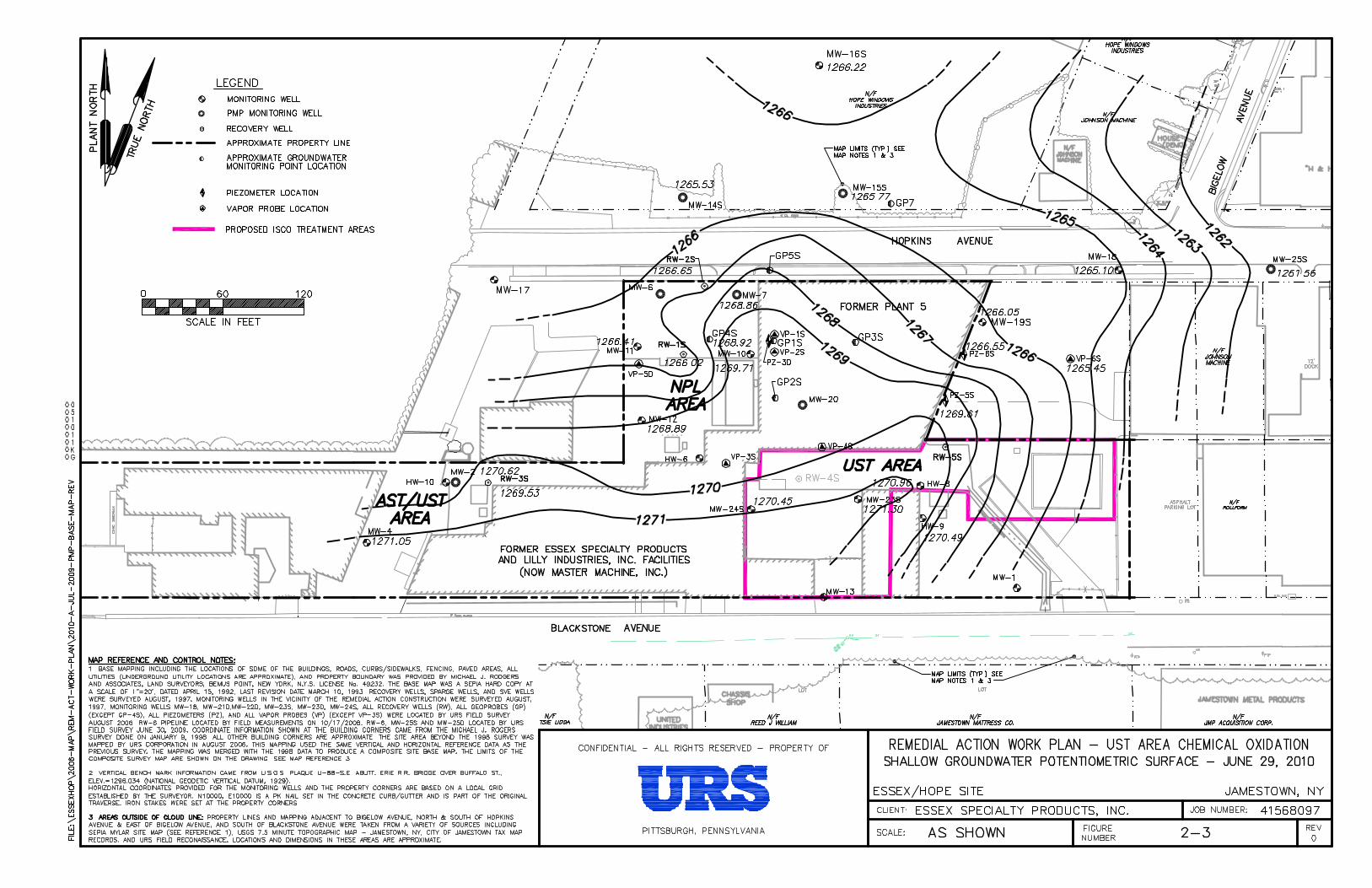
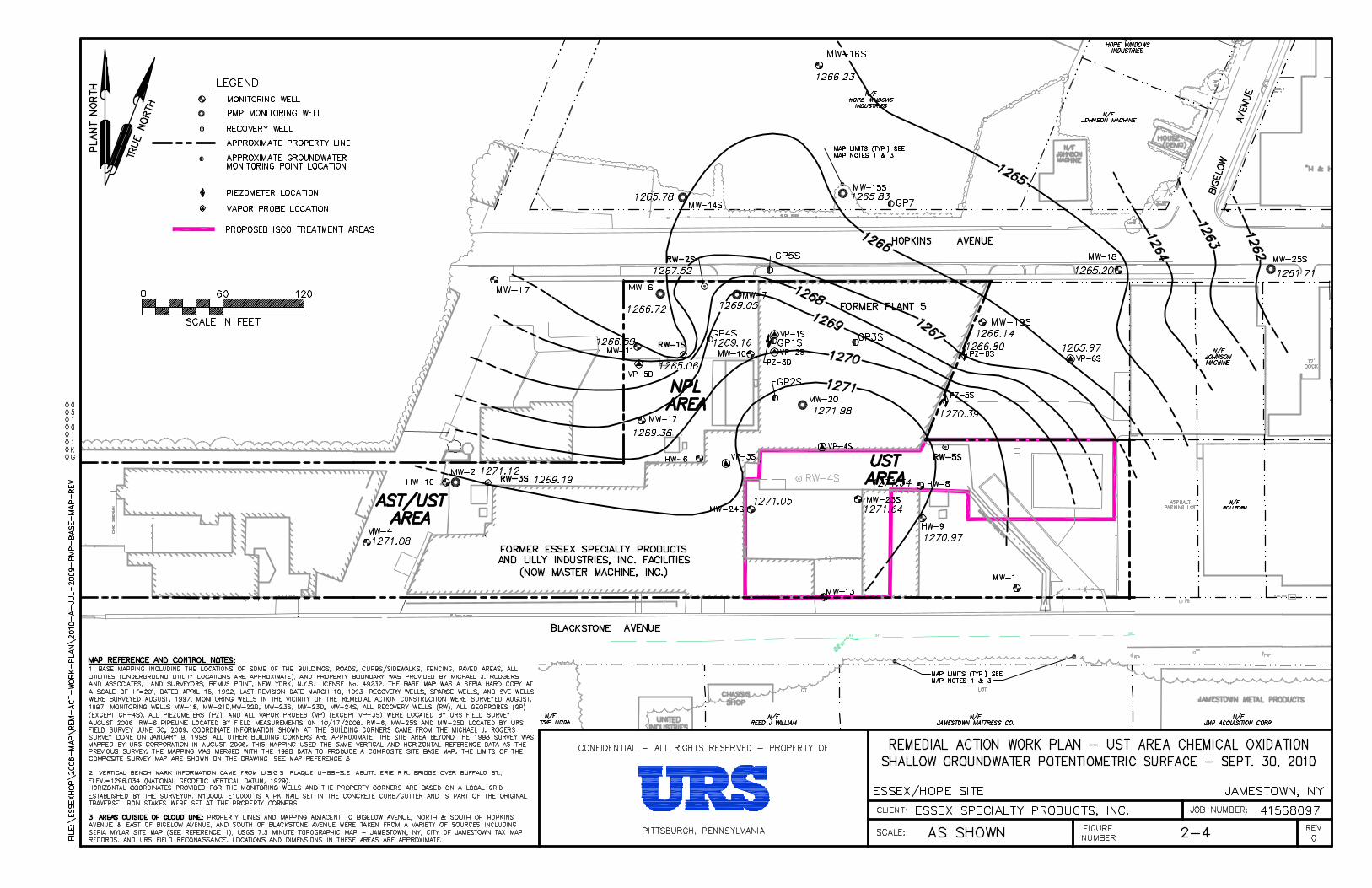
Groundwater contours representing normal pumping conditions are contained in the
Annual Reports and have been depicted in other site investigation reports. The most recent (June
and September, 2010) potentiometric surface contour maps for the shallow groundwater zone are
presented on Figures 2-3 and 2-4, respectively.

3-1
3.0 SUMMARY OF SITE CONTAMINATION
The nature and extent of contamination at the site were characterized through the
completion of various site investigations conducted from 1992, beginning with the CERCLA
Remedial Investigation, up to 2009 with the most recent UST Area investigations. The
investigations of interest occurred after removal of the USTs and contaminated soil in 2003.
The results of these previous site investigations are summarized in this section. Soil and
groundwater data are summarized on Tables 3-1 and 3-2, Figures 3-1 and 3-2, and Appendix A.
UST Area investigation history is summarized in Appendix A. Test boring and monitoring well
locations are shown on Drawing C-1. Geologic cross-sections are shown on Drawing C-7.
3.1 Soil Analytical Results
A total of 36 test borings were drilled to assess soils in the UST Area after removal of the
tanks and contaminated soils. Twelve (12) borings were completed in 2003, designated TBUST-1
through TBUST-12. These borings focused on the vadose zone soils in the areas directly south
and east of the former USTs. The remaining test borings TBUST-13 through TBUST-36 were
completed in 2005-2006. These test borings were located beyond the previous investigations to
determine the extent of VOCs. The test borings were advanced using direct-push drilling and
sampling techniques. Continuous soil samples were collected from ground surface to the top of
the upper semi-confining layer, located at approximately 12 to 16-feet in depth. All soil analyses
from the UST Area are summarized on Table 3-1.
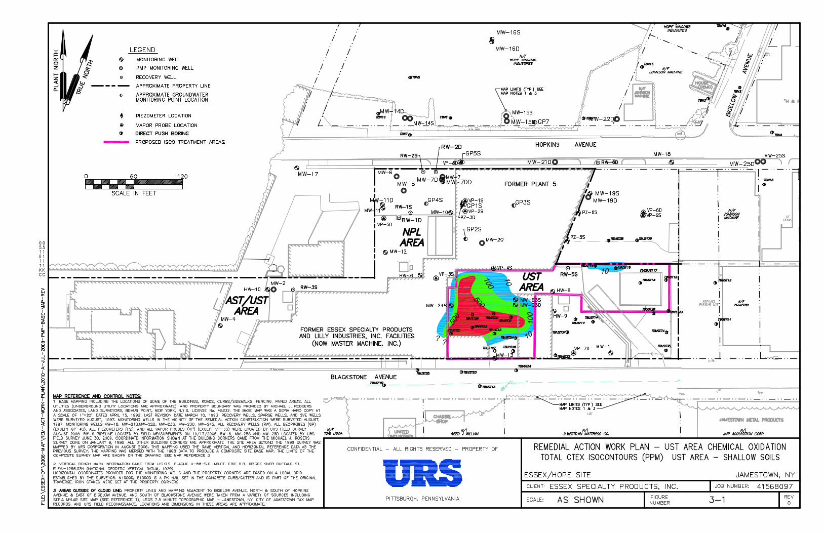
VOC‘s cumene, toluene, ethylbenzene and xylenes (CTEX) were most frequently
detected in the UST Area soils. Chlorinated VOCs were not detected. The CTEX compounds
were found at levels above the Remedial Action Objectives (RAOs primarily in the western end
of the UST Area, around former Tank T1. The elevated CTEX soil areas generally correlate with
the elevated CTEX in shallow groundwater. (See Section 3.2). These elevated CTEX areas are in
the historic truck access aprons for chemical deliveries and loading for the former UST Area
operations. The area is currently paved with concrete and is used as an access and parking area
3-2
for the Master Machine Inc. plastic and metal working operations in the building directly west.
See Figure 3-1 for a depiction of soil CTEX distribution.
3.2 Groundwater Analytical Results
Shallow zone groundwater samples have been taken from two newer monitoring wells
(MW-23S and MW-24S) and seven existing monitoring wells in the UST Area. In 2006, test
borings were advanced in the UST Area and adjoining properties for retrieval of shallow
groundwater samples by direct-push drilling methods. Groundwater samples were taken from a
short screened interval (~ 4 ft. or less) either near the top of the semi-confining layer (average 16
ft. BGS) or the top of the saturated zone (approximately 10-12 ft. BGS). All shallow groundwater
analyses for the UST Area are summarized on Table 3-2.
Consistent with the UST soils analyses, groundwater analyses indicates that the CTEX
volatile organics (cumene, toluene, ethylbenzene and xylenes) were the dominant compounds
detected in the UST Area. Chlorinated VOCs were found at relatively low levels.
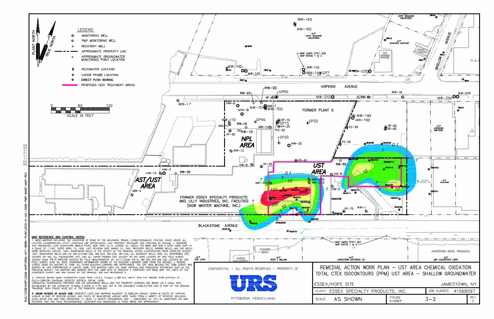
The CTEX groundwater plume (1 ppm isocontour) extends across the entire UST Area to
the former tank farm to the east, north to MW-20 (beneath Plant #5), and to the southwest, and
has been delineated in the recent investigations. The extent of the plume to the southwest and
eastern areas of the UST Area has been determined to be offsite onto adjoining properties. The
mean CTEX concentrations in the western portion of the UST Area are 1 to 2 orders of
magnitude greater than the mean CTEX concentrations in the eastern part of the UST Area. The
shallow groundwater CTEX distribution is presented on Figure 3-2.
The only monitoring well in or near the UST Area that is routinely sampled is MW-20,
beneath CPM Building No. 5. This well is within the shallow groundwater zone and it is
hydraulically downgradient of the UST Area. The most recent data (2010) shows that CTEX
levels have decreased to below detection limits (BDL). The total VOC levels in MW-20 have
been decreasing continuously since a maximum recorded value of 83.7 ppm was found in 2000.
MW-20 VOC data from years 2000 to 2010 is as follows:

3-3
83.7
40.4
21.6
44.3
27.3
10.2
6.2
0.54 0.06 0.04 0
0
10
20
30
40
50
60
70
80
90
2000 2001 2002 2003 2004 2005 2006 2007 2008 2009 2010
Total V
OCs, m
g/l
Year
MW‐20 ‐ Total VOCs, Years 2000‐2010
The reason for the significant decline in VOCs in downgradient monitoring well MW-20
has not been determined. Pre-work baseline groundwater sampling in the UST area will establish
the current CTEX distribution in the shallow groundwater zone. See Section 5.5.

4-1
4.0 PROPOSED REMEDIAL ACTION
4.1 General
The proposition of a supplemental remedial action at the UST Area was based on the
limited performance of the original remedial measures (pumping shallow groundwater with soil
vapor extraction) and the identification of more extensive site contamination. The discovery of
the inadequately closed USTs and the residual VOC contamination surrounding the tanks after
their removal prompted assessment of other remedial actions.
After removal of the USTs, URS conducted a series of subsurface investigations in the
UST Area to define the extent of the contamination (See Section 3.0). Based on a preliminary
evaluation of potential technologies, chemical oxidation was determined to be a feasible and cost-
effective approach for treatment of the residual site VOCs. The predominant VOCs in the UST
Area, CTEX, were amenable to chemical oxidation treatment based on review of remediation
literature and URS experience with oxidation technologies. URS subcontracted VeruTek in 2010
to perform a bench-scale treatability study for chemical oxidation of UST Area soil and
groundwater. The results of the study proved favorable for oxidation of the site contaminants with
activated sodium persulfate, combined with a surfactant. Based on the site conditions and the
results of the treatability studies, insitu chemical oxidation was selected as the preferred remedial
action for the UST Area.
It is expected that multiple applications of oxidant would be required to achieve the site
RAOs if insitu chemical oxidation alone is employed for remediation of the UST Area.
Performance monitoring of the initial oxidant application will provide data on treatment
effectiveness and residual VOCs, post-treatment. See Section 5.10. The results of the monitoring
will be evaluated to determine the most feasible remedial actions to address residual VOCs.
Additional chemical oxidation will be considered, and other approaches will also be assessed,
including bio-enhancement and natural attenuation. A supplemental RAWP will be prepared, if
necessary, to present proposed further remedial actions for the UST Area.

4-2
4.2 Chemical Oxidation Treatability Study
A laboratory treatability study was performed to evaluate the effectiveness of chemical
oxidation for reducing VOCs present in the UST Area. VeruTEK Technologies, Inc. of
Bloomfield, CT performed the study. URS collected representative soil samples for the study
from across the UST Area and from a depth of approximately 4-12 ft. BGS. A summary of the
treatability study samples, including field VOC headspace results are contained in Appendix B.
The sample locations are shown on Drawing C-1.
Oxidants sodium persulfate and hydrogen peroxide, with and without surfactant
augmentation, were used in the testing. The oxidants were blended with catalytic activators. The
surfactant was a plant-based extract (citrus oil) that is naturally biodegradable: VeruSOL-3. Batch
emulsion and soil column tests were performed. The treatability study report is contained in
Appendix B. A summary of the treatability study is as follows:
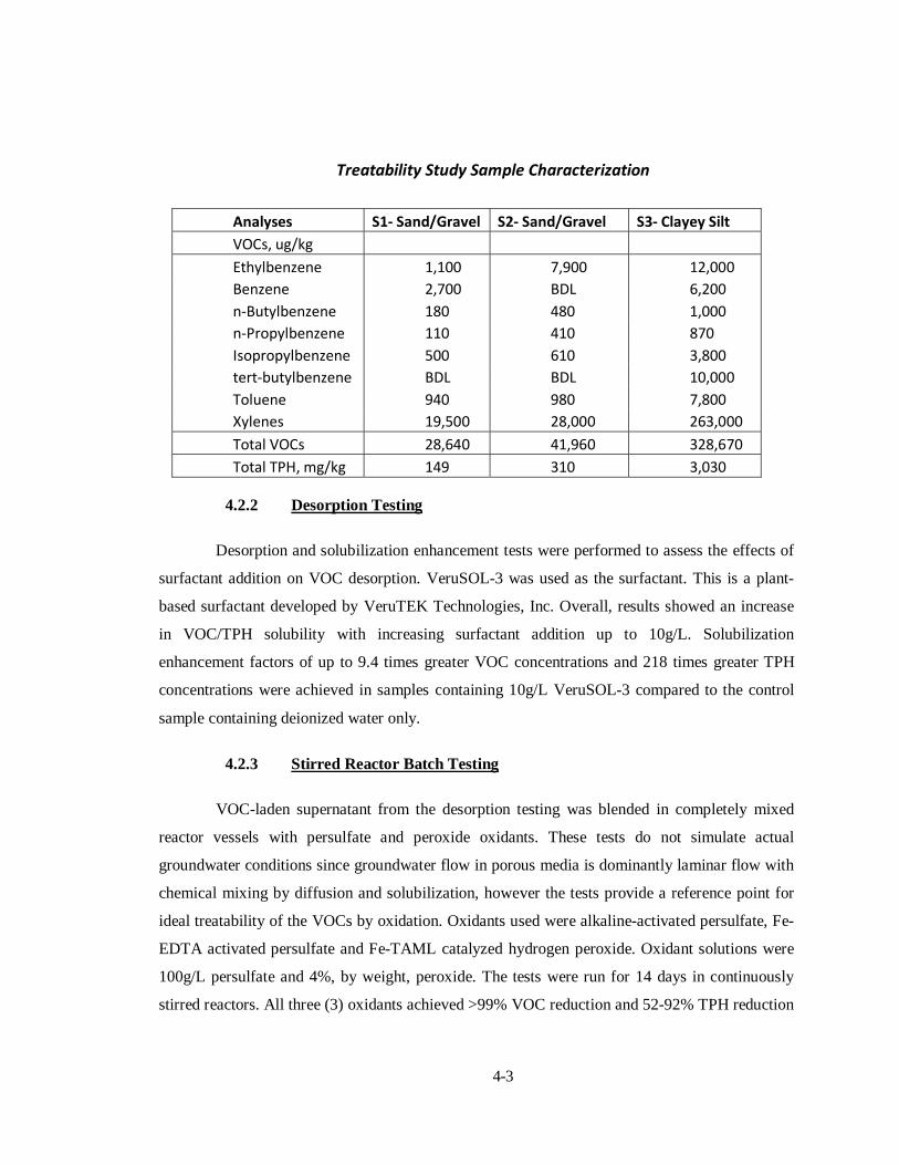
4.2.1 Test Sample Baseline Characterization
Soil samples were composited and characterized prior to testing. The samples
were primarily sand and gravel with clayey silts from interspersed lens throughout the site area.
The clayey silt fraction was manually separated from the samples for characterization. A
summary of the pre-treatment sample chemical analyses data is as follows:
4-3
Treatability Study Sample Characterization
Analyses S1‐ Sand/Gravel S2‐ Sand/Gravel S3‐ Clayey Silt
VOCs, ug/kg
Ethylbenzene 1,100 7,900 12,000
Benzene 2,700 BDL 6,200
n‐Butylbenzene 180 480 1,000
n‐Propylbenzene 110 410 870
Isopropylbenzene 500 610 3,800
tert‐butylbenzene BDL BDL 10,000
Toluene 940 980 7,800
Xylenes 19,500 28,000 263,000
Total VOCs 28,640 41,960 328,670
Total TPH, mg/kg 149 310 3,030
4.2.2 Desorption Testing
Desorption and solubilization enhancement tests were performed to assess the effects of
surfactant addition on VOC desorption. VeruSOL-3 was used as the surfactant. This is a plant-
based surfactant developed by VeruTEK Technologies, Inc. Overall, results showed an increase
in VOC/TPH solubility with increasing surfactant addition up to 10g/L. Solubilization
enhancement factors of up to 9.4 times greater VOC concentrations and 218 times greater TPH
concentrations were achieved in samples containing 10g/L VeruSOL-3 compared to the control
sample containing deionized water only.
4.2.3 Stirred Reactor Batch Testing
VOC-laden supernatant from the desorption testing was blended in completely mixed
reactor vessels with persulfate and peroxide oxidants. These tests do not simulate actual
groundwater conditions since groundwater flow in porous media is dominantly laminar flow with
chemical mixing by diffusion and solubilization, however the tests provide a reference point for
ideal treatability of the VOCs by oxidation. Oxidants used were alkaline-activated persulfate, Fe-
EDTA activated persulfate and Fe-TAML catalyzed hydrogen peroxide. Oxidant solutions were
100g/L persulfate and 4%, by weight, peroxide. The tests were run for 14 days in continuously
stirred reactors. All three (3) oxidants achieved >99% VOC reduction and 52-92% TPH reduction

4-4
compared to the control sample. The residual TPH presence in the treated samples is expected to
be due in large part to the presence of VeruSOL-3 surfactant which contains plant oils known to
cause false positive TPH readings. The VeruSOL-3 is expected to be further oxidized over time
under in-situ field conditions.
The batch reactor tests were run in 500 ml flasks using 100g/L persulfate and 4%
peroxide solutions. Based on the control sample VOCs and TPH concentrations, assuming
minimal organic degradation, the oxygen/organic mass ratio was approximately 3:1 for the
sodium persulfate reactors. Although natural organic matter was not measured in the test, its
effects on the overall oxygen demand, and VOC treatability, were accounted for in the testing.
4.2.4 Soil Column Testing
Soil column tests were performed to simulate saturated soil treatment conditions in the
field. The tests consisted of a control column, an Fe-EDTA activated persulfate treated column,
an alkaline activated persulfate treated column, and an Fe-TAML catalyzed hydrogen peroxide
treated column, each applied with and without VeruSOL-3. Oxidant solutions were 100g/l of
sodium persulfate and 4% hydrogen peroxide. The persulfate columns were run for 28 days and
the peroxide columns were run for 14 days. The difference was based on the expected reactivity
of the two oxidants.
Soil samples were selected from sacrificed columns at the completion of the testing.
Sampling and analyses of column effluent was performed after one pore volume was generated
(Day 1) and on various days thereafter. Each column experienced a minimum 1 PV/day.
Overall, the treated columns exhibited decreased VOC levels compared to the control
columns, with the exception of the Fe-TAML hydrogen peroxide column without surfactant. This
exception is likely due to running the column for 14 days which is not expected to be sufficient
time for VOC desorption. In all cases, the surfactant enhanced columns achieved significantly
better VOC removals than the comparative oxidant-only columns. The Fe-EDTA persulfate and
Fe-TAML hydrogen peroxide columns with VeruSOL-3 achieved VOC reductions to levels less
4-5
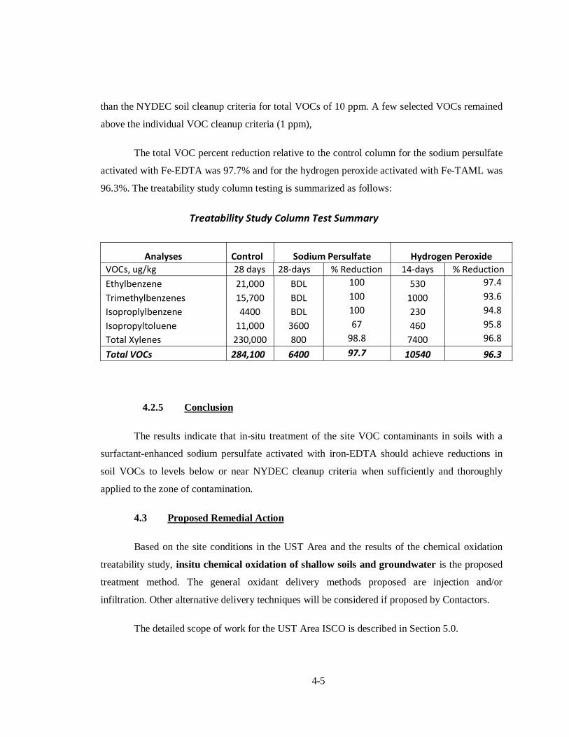
than the NYDEC soil cleanup criteria for total VOCs of 10 ppm. A few selected VOCs remained
above the individual VOC cleanup criteria (1 ppm),
The total VOC percent reduction relative to the control column for the sodium persulfate
activated with Fe-EDTA was 97.7% and for the hydrogen peroxide activated with Fe-TAML was
96.3%. The treatability study column testing is summarized as follows:
Treatability Study Column Test Summary
Analyses Control Sodium Persulfate Hydrogen Peroxide
VOCs, ug/kg 28 days 28‐days % Reduction 14‐days % Reduction
Ethylbenzene 21,000 BDL 100 530 97.4
Trimethylbenzenes 15,700 BDL 100 1000 93.6
Isoproplylbenzene 4400 BDL 100 230 94.8
Isopropyltoluene 11,000 3600 67 460 95.8
Total Xylenes 230,000 800 98.8 7400 96.8
Total VOCs 284,100 6400 97.7 10540 96.3
4.2.5 Conclusion
The results indicate that in-situ treatment of the site VOC contaminants in soils with a
surfactant-enhanced sodium persulfate activated with iron-EDTA should achieve reductions in
soil VOCs to levels below or near NYDEC cleanup criteria when sufficiently and thoroughly
applied to the zone of contamination.
4.3 Proposed Remedial Action
Based on the site conditions in the UST Area and the results of the chemical oxidation
treatability study, insitu chemical oxidation of shallow soils and groundwater is the proposed
treatment method. The general oxidant delivery methods proposed are injection and/or
infiltration. Other alternative delivery techniques will be considered if proposed by Contactors.
The detailed scope of work for the UST Area ISCO is described in Section 5.0.

5-6
5.0 REMEDIAL ACTION SCOPE OF WORK
This section describes the scope of work for implementation of ISCO of the UST Area.
The selected Contractor will be required to submit a Field Operations Work Plan (FOWP),
including a Health and Safety Plan that outlines all of the field operations and requirements for
implementation of the project. The scope of work outlined herein shall be followed at a
minimum, and any modifications to this scope must be approved by URS/Dow and if necessary
the NYDEC. Major changes to the scope of work as described in this section will be documented
and submitted to NYDEC for approval prior to implementation in the field.
5.1 Stormwater Drainage System Modifications
The existing stormwater drainage system for CPM Building No. 5 in the UST Area will
be modified to eliminate infiltration to local shallow groundwater in the UST Area. The three (3)
drywell sumps will be closed in-place, and the Building 5 roof drainage waters will be conveyed
to the City of Jamestown stormwater sewer on Blackstone Avenue. A new stormwater pipe
system will be constructed that connects the three main roof drain pipes to a new storm sewer
catch basin constructed adjacent to Blackstone Avenue. The existing drainage system is described
in Section 2.3.
Preliminary design requirements have been provided by the City of Jamestown. The city
is currently performing field surveys of their sewer and stormwater systems which will be
provided to URS for preparation of final designs.
5.1.1 Drywell Closure
The drywells will be closed in-place by backfill with clean fill. Portions of the drywell
walls may be demolished to allow routing and/or connections for the new stormwater pipe.
Backfill material will be placed to the top of the drywell walls. The existing concrete lids shall be
demolished.

5-7
5.1.2 New Stormwater Drainage System
The three (3) existing stormwater drainage pipes will be cut near the CPM Building 5
south foundation wall, upstream of their connection to the drywells. Individual inlet boxes will be
constructed at each new connection. HDPE drainage pipe will be used for the new stormwater
drains. All three inlet boxes will discharge to a new junction box inlet constructed onsite. The
junction box will discharge to a new stormwater catch basin connected to the Blackstone Avenue
storm sewer.
Engineering calculations and design details will be prepared and be submitted to the City
of Jamestown for approval. A city construction permit will be obtained by the Contractor prior to
starting the work.
Preliminary design of the stormwater system modifications is presented on Drawing C-3.
5.2 Permits
URS/Dow will obtain all necessary permits for the ISCO project, unless it proves to be
more appropriate for the selected Contractor to obtain construction work and other local permits.
A USEPA Underground Injection Control (UIC) Permit will be required to perform the
work. URS will prepare all necessary documentation for implementing the project, including this
RAWP, and will submit that information to USEPA Region II for approval. A USEPA
“authorization by rule” approval is anticipated.
The Contractor shall obtain all necessary local permits required for the performance of
the remedial activities. These permits will include at least the following:
City of Jamestown Construction Permits for stormwater drainage system and any
other work in city right-of-ways,
City of Jamestown permits for water line access and metering for onsite supply.

5-8
5.3 Construction Health and Safety Plan
The Contractor will be responsible for preparing a Construction Health and Safety Plan
(CHASP) and implementing the CHASP. An existing Health and Safety Plan (HASP) has been
prepared by URS for the Essex Jamestown Site that outlines all requirements necessary for
compliance with OSHA 1910.120 HAZWOPER regulations and any other applicable general
construction requirements. The HASP sets out personnel protection and action levels and
establishes procedures and specifies H&S controls such as exclusion and decontamination zones.
The URS HASP will be provided to the Contractor for reference purposes only. The CHASP will
be reviewed and approved by URS prior to commencement of site work.
The Contractor will be responsible for conducting air monitoring within his work zones
and taking appropriate action based on the results. Compliance with the CHASP will be
maintained throughout the planned Remedial Action. It is expected that all intrusive Site work
(i.e. soil excavation and injection ) will be conducted under Level D, but PPE levels will be
adjusted as per the HASP, based on air monitoring results.
Air monitoring will be conducted in accordance with the requirements of the CHASP.
Dust control measures will be implemented by the Contractor as required to meet the
requirements of the CHASP.
Based on the Site’s size, location, and setting, no impact to nearby residents is expected
as a result of the planned Remedial Action.
Notification of residents and all necessary site access will be obtained by URS/Essex.
Periodic air monitoring will be performed at perimeter and interior building locations for
VOC’s during intrusive (injection) work, and fugitive emissions control measures outlined in the
CHASP will assure that there will be no impact to residents.
The basic elements of the plan are as follows:
Project personnel and responsibilities
5-9
Training requirements and documentation
Medical surveillance requirements
Activity hazards analyses
Site work zones
Personnel protective equipment
Monitoring requirements
Emergency response plan, including spills and fugitive emissions control
measures
Decontamination procedures
5.4 Mobilization & Site Preparation
The Contractor will be responsible for mobilization and site setup. General work zones
and site preparation measures are shown on Drawing C-2. The Contractor will procure and
transport the necessary resources to accommodate the project requirements (i.e. labor, materials,
and equipment). Other requirements not specifically provided herein, but necessary for the
successful conduct and completion of the work, will be provided by Dow or URS to the
Contractor.
The UST Area is currently surrounded by a 6-ft high steel security fence with locking
gates. Work and staging areas will be maintained inside of the perimeter fencing. All access to the
site shall be via Blackstone Avenue and the two south perimeter gates.
Locating and marking underground utilities that may potentially be affected during site
work will be required. Existing underground utilities/piping identified by URS to-date are shown
on Drawing C-1.
Site preparation activities include the following operations:

5-10
Clearing of debris (e.g. scrap equipment and materials, vegetation, etc.), as
necessary to access the work areas. All materials are to be staged in areas
identified by URS.
Installation of five foot high, orange plastic construction safety fencing mounted
on driven steel fence posts at 10 foot spacing around active work areas. Signs
designating the work area and warning against trespass will be affixed to all sides
of the fence during the construction period.
Construction of temporary decontamination pad for personnel and equipment.
The existing concrete pad on the east end of the site shall not be used for
decontamination, however, it overlies the eastern injection area and it may be
compromised if oxidant injections are conducted through the concrete pad.
Mobilization of chemical injection and mixing equipment, reagent storage and
application equipment, tanker trucks and necessary personnel.
5.4.1 Temporary Facilities
The proposed locations and extent of areas for Contractor temporary facilities, including
any staging areas is shown on Drawing C-2. Limited water may be provided by URS for
incidental uses, if necessary from the URS treatment building, as its supply is limited to a 5-10
gpm city water tap. The Contractor is responsible for locating and obtaining an adequate potable
water supply for project needs.
Contractor shall provide a suitable small Site Office/Work Area to be used by Project
Management and NYSDEC personnel during work onsite.
Contractor shall provide portable sanitary facility for site workers.
5.4.1.1 Employee Parking
Contractor employees shall park privately owned vehicles in area designated by URS.

5-11
5.4.1.2 Availability and Use of Utility Services
The Contractor is responsible for providing all temporary utility services required during
construction.
5.4.1.3 Storage Areas
The Contractor shall designate a storage area in a portion of the Site, as approved by
URS. Materials shall not be stockpiled outside the designated area in preparation for the next
day’s work. Mobile equipment, such as drilling rigs, mixers, and trucks, shall be parked within
the designated area at the end of each work day, unless otherwise approved by URS.
The storage area will be kept in good repair. Should the Contractor elect to traverse, with
construction equipment or other vehicles, grassed or unpaved areas that are not established
roadways, such areas shall be protected as necessary to prevent rutting and the tracking of mud
onto paved or established roadways.
5.4.2 Protection and Maintenance of Traffic
During construction the Contractor shall maintain and protect traffic on Blackstone
Avenue when necessary. Measures for the protection and diversion of traffic, including the
provision of watchmen and flagmen, erection of barricades, placing of lights around and in front
of equipment and the work, and the erection and maintenance of adequate warning, danger, and
directional signs, shall be in accordance with applicable State and local laws. The traveling
public shall be protected from damage to person and property. The Contractor shall investigate
the adequacy and allowable load limit on these roads. The Contractor shall be solely responsible
for the repair of any damage to roads caused by construction operations.
5.4.3 Security Provisions
The Contractor shall be responsible for the security of its own equipment. If the Site is
used for staging or storage of equipment and supplies, the Contractor shall be responsible for
securing all vehicle gates and man gates at the end of each work day.
5-12
A daily visitor’s log will be maintained to document all visitors to the site.
5.4.4 Erosion and Sediment Control
In accordance with New York Guidelines for Urban Erosion and Sediment Control (New
York 1997), an erosion and sediment control plan must be prepared for any construction activity
that exceeds 1 acre in size.
During construction activities, erosion and sediment controls will be incorporated to
minimize storm water contacting disturbed areas and to control runoff. Silt fences shall be
installed around excavation areas and around the soil storage areas.
5.4.5 Equipment Decontamination
Vehicles and equipment that come into contact with affected media shall be
decontaminated prior to leaving the site. The Contractor shall utilize procedures for
decontamination of vehicles and equipment as outlined in the CHASP.
Injection rods and equipment in direct contact with oxidant solutions should be cleaned
daily. This includes injection pumps, delivery hose/piping and batch mixing tanks.
Pressurized water with a detergent solution (Alconox or equivalent) is preferred. A
temporary decontamination pad shall be established on-site that is of suitable size and provides
containment of all decon liquids and solids. The decon wastes shall be collected and disposed
offsite in accordance with NYDEC and City of Jamestown requirements. Some decon wastes may
be returned to the site upon the approval of URS .
5.4.6 Spill and Discharge Control
The Contractor shall prepare a Spill and Discharge Control Plan. The Spill and
Discharge Control Plan will be part of the CHASP and is to be implemented in the event of an
accidental release of potentially hazardous materials and shall contain the following elements:
5-13
Preventive Measures – the Contractor shall provide methods, means, and
facilities required to prevent contamination of soil, water, atmosphere,
uncontaminated structures, equipment, or material by the discharge of wastes
from spills due to the Contractor’s operations. Shovels, brooms, non-
combustible sorbent materials, polyethylene sheeting, and PPE shall be
maintained in accessible locations.
Emergency Measures – the Contractor shall provide equipment and personnel to
perform emergency measures required to contain any spillage and to remove
spilled materials, soil, or liquids that become contaminated due to spillage. The
collected spill materials shall be properly disposed of at the Contractor’s expense.
Decontamination Measures – the Contractor shall provide the equipment and
personnel to perform decontamination measures that may be required to remove
spillage from previously uncontaminated structures, equipment, or material.
Disposal of decontamination residues and confirmation samples shall be
performed at the Contractor’s expense.
Notification Procedure – the Contractor shall notify URS immediately after the
release of potentially hazardous materials as well as the National Response
Center and NYSDEC Hotline, as required (applicable phone numbers must be
listed in the HASP).
5.4.7 Survey and Work Stake-out
The Contractor will be responsible for staking out the limits of work in the field as shown
on the drawings. The exact locations of treatment areas and excavations will be staked from
established control points. Survey crews utilizing traditional survey equipment and/or GPS
equipment, as appropriate, will be employed. Each injection point will be numbered for
identification purposes and the depth of injection clearly shown for each area of the site.
5-14
5.5 Baseline Groundwater Sampling
Existing monitoring wells and discrete groundwater sampling will be conducted by USR
prior to initiating the project bidding and procurement process. The objective of the sampling
will be to confirm the extent and nature of VOCs in the UST Area shallow groundwater zone and
provide a baseline for ISCO performance. Any significant changes in the VOC characterization
from current interpretations outlined in Section 3.0 may require a modification to the ISCO
implementation plan. Major changes to the plan will be submitted to NYDEC for review. All data
and revised ISCO plans and treatment zones, if prepared, will be provided to the Contractors prior
to final project bidding.
5.6 Pre-Work Injection and Infiltration Field Tests
Prior to commencing full-scale treatment operations, field testing will be performed by
the Contractor in representative treatment area locations to confirm injection and infiltration
hydraulic design guidelines. These tests include injection and test pit infiltration tests using clean
water. URS will monitor the testing and prepare a pre-work testing memorandum. The findings of
the testing will be reviewed and modifications to the chemical oxidation treatment guidelines will
be made if necessary.
5.6.1 Injection Test
An injection test shall be conducted in the shallow groundwater zone in the area directly
east of the metal building (near well HW-9). The vertical test interval will be approximately 10-
18 ft. BGS. Test criteria area as follows:
Advance test injection point 5-ft from existing monitoring well HW-9, to the
maximum test depth (18 ft. BGS).
Injection clean water at a rate equivalent to 0.5, 1.0 and 2.0 times the calculated
maximum injection pressures (Pm) as measured at the injection rod head. The
estimated Pm’s for the site are 8-10 psi for depths of 10-15 ft.

5-15
Inject a minimum 0.5 pore volumes (PV) of water per foot interval over the range
of injection pressures. The estimated PV per foot for a 10-ft injection spacing is
224 gallons (at porosity = 0.3).
Record the time, depth, injection pressure, water volume, flow rate and any other
notable conditions observed during the tests. Measure the water levels in the
adjacent monitoring well (HW-9) pre-test, and at intervals not to exceed 30
minutes during each test. Record a minimum three measurements per test.
Adjustments to the injection test criteria may be made as a result of initial
performance of the tests. All modifications will be communicated to and
subsequently approved by URS prior to revising the testing criteria.
5.6.2 Infiltration Test
An infiltration test shall be conducted to assess area infiltration hydraulics prior to the
full-scale infiltration of chemical oxidant. The test will in the vadose zone in the area directly
west of the metal hut building, near monitoring well MW-23S. The vertical test interval will be
the unsaturated zone above the water table, approximately 4-8 ft. BGS. Test criteria area as
follows:
Advance three (3) test pit excavations at a distance of 5 ft from existing
monitoring well MW-23S. The test pits shall be approximately 2 ft. in width and
a minimum 5 ft. in length at the bottom. The pits will be required to be excavated
at depths of 2, 4 and 6 ft BGS. Orientations of the three pits will be north, west
and south of the monitoring well. Seepage tests will be done at each 2 ft depth
interval, starting at 2 ft. BGS. A minimum of 30 minute interval will be required
between each test to allow water seepage from the excavation bottom.
Fill the pit with clean water to achieve a 1-ft deep liquid depth.
Record the time, water depth, total water volume, any other notable conditions
observed during the tests over the period required to drain the initial water
5-16
volume completely into the subsurface. Measure the water levels in the
adjoining monitoring well (MW-23S) pre-test, and at intervals not to exceed 10
minutes during each test. Record a minimum three measurements per test.
After all of the tests are completed, backfill the test pit to original grade.
Adjustments to the infiltration test criteria may be made as a result of initial
performance of the tests. All modifications will be communicated to and
subsequently approved by URS prior to revising the testing criteria.
5.7 Chemical Oxidation Implementation Plan
The objective of the chemical oxidation of the UST Area is to achieve NYDEC cleanup
objectives for site contaminants in soil and groundwater throughout the designated zones of
treatment.
The UST Area presents some challenges for delivery of the oxidant to the zones of
interest. These include the shallow distribution (4-8 ft. BGS) of the highest levels of
contamination, the wide range of contaminant concentrations observed across the site (1-500
ppm), including minor groundwater VOC impacts of 1 ppm or less, and the shallow groundwater
table (6-8 ft. BGS)..
The shallow depth of the vadose zone VOCs, and the overall site in general, limits the
ability to inject oxidants at high pressures because of concerns with ground uplift, oxidant surface
breakthrough, and groundwater mounding. The nearly three (3) orders of magnitude range of
VOC concentrations increases the complexity of onsite preparation and delivery of optimum
oxidant dosages. For example, the relatively low VOC levels require an equivalent low dosing of
oxidant, however, the distribution of the oxidant by pore volume requires a site-wide fixed
volume of solution, and thus a correspondingly very dilute ( low % oxidant) solution for the low
VOC areas. The high VOC areas conversely require a relatively concentrated solution (high %
oxidant).

5-17
The RAWP proposes two (2) oxidant delivery methods as a performance specification
with a preference for injection and shallow zone infiltration. Infiltration methods may be by
trenches or open area (blanket). Alternative delivery methods will be considered by URS/Dow if
proposed by the Contractor.
The proposed treatment areas are based on the existing investigation database. See
Section 3.0. These areas may be modified based on the results of the pre-work confirmatory
baseline sampling as described in Section 5.5.
Two (2) treatment zones have been designated and are identified as follows:
West Area- High VOC area of soil and shallow groundwater
East Area- Low VOC area of soil and shallow groundwater
These areas are shown on Drawing C-3. The extent of the groundwater treatment areas
may be modified as a result of the pre-work baseline sampling.
5.7.1 InSitu Treatment Design Guidelines
General performance guidelines have been established for chemical oxidant formulation
and delivery to the treatment zones of interest. These guidelines are intended as preliminary
requirements for implementation of insitu chemical oxidation at the site. The pre-work water
injection and infiltration tests and full-scale field performance will provide actual site-specific
data that can be used to modify these guidelines as necessary. All major field modifications to the
oxidant formulation and delivery system must be approved by URS/Dow.
Design calculations are contained in Appendix C.
5.7.1.1 Treatment Zone Pore Volume
The UST area soil pore volumes (PVs) were estimated to provide an indicator of the
oxidant solution reference volume required to saturate the treatment zone. PVs were estimated
based on a porosity of 0.3. Unit pore volumes (per/ft.) were estimated for a range of injection

5-18
point spacings and for infiltration areas (per sq. ft.). A square injection area was assumed for the
calculations to account for the entire surface area, although the radius of influence at injection
may be typically more circular.
One (1) PV is the baseline volume for fully saturated distribution of the oxidant to the
contaminants in the treatment zone. The total treatment zone, vadose plus saturated zones, has an
estimated PV of 415,364 gallons at a porosity of 0.3. The average PV is 2.24 gallons per square
foot/foot. For the site design injection spacing of 10 foot, the per point PV is estimated at 2693 to
3142 gallons, depending on the formation thickness (12-14 ft). This volume will vary throughout
the site based on actual effective porosity and treatment zone thickness. The capacity of the
formation to accept 1 PV in a reasonable time frame is critical to critical to achieving a cost-
effective remedial action. The formation acceptance rate and time estimates are evaluated later in
this section. See Table C-1 for the PV estimates.
5.7.1.2 Injection Pressure Guideline
Maximum in-situ injection pressures were estimated over the thickness of the treatment
zone, approximately 6 to 16 feet BGS. A shallow zone average hydraulic conductivity of 2.69
ft./day used in the estimate was determined from a series of well slug tests performed in the UST
Area. The mitigating effects of soil tensile strength resistance was neglected to allow a
conservative estimate. Because the injection zone is relatively shallow, injection pressures will
need to be monitored and controlled to prevent surface uplift and fluid return.
For the range of injection depths, maximum injection pressures (insitu) were estimated at
5.0 to 9 psi, with allowable pressure increasing with depth of the injection point. See Table C-2
for the injection pressure estimates.
The time to inject one pore volume of liquid was estimated over a range of injection
pressures. The injection time is critical to deliver the oxidant in a reasonable time frame to reduce
operations costs. A target delivery time per injection point of 0.5 to 2.0 hours per point, or less, is
desirable.

5-19
Over the range of maximum injection pressures previously calculated, the injection times
will likely range from about 90-175 minutes per point for 10 ft injection spacings and 5-10 psi
injection pressures. The greater time frame is for the shallow zone (vadose) at the site. These
estimates do not take into account the injection effects on groundwater mounding. See Table C-3
for the injection time estimates.
5.7.1.3 Hydraulic Acceptance Rate
The hydraulic acceptance rate of the formation was evaluated to estimate the operating
limits to prevent groundwater mounding during injection. The shallow groundwater saturated
zone was conservatively estimated at 6 ft. BGS, although the depth varies over the site and over
the year and is typically deeper than 6 ft..
In general, the acceptance rate will decrease as the groundwater levels rise because of the
back pressure caused by the groundwater mound. For injection, the acceptance rate also increases
with depth because the allowable injection pressures also increases with depth.
The acceptance rates range from 6.7 to 13 gallons per minute (per injection point) at a
groundwater mounding of 2 ft., and from 1.3 to 3.4 gpm at a mounding 6 ft., for injection depths
ranging from 6 to 15 feet BGS, respectively. See Table C-4 for the injection acceptance rates.
For the minimum one (1) PV injection requirement of 224 gal/ft. injection (10 ft.
spacing), the injection times would range from 17 to 172 minutes per injection point, depending
on the depth and degree of mounding. The upper end of this range is within the injection time
range estimated for the range of acceptable pressures. See Section 5.7.1.2.
For infiltration, assuming a mounding of 4 ft. (2-ft below ground surface), the infiltration
rate can be estimated by Q = K * i * A, where the vertical gradient is the depth of the infiltration
head. At a 1 ft. head, the nominal infiltration rate is 20 gpd/sf. This rate will increase with
increasing the depth of the applied infiltration solution.

5-20
5.7.1.4 Oxidant Formulation
The oxidation treatability study evaluated three different oxidant-activator combinations,
each applied with and without surfactant addition. Based on the results of the study, sodium
persulfate activated with iron-EDTA, in combination with the VeruSOL-3 surfactant, is the
proposed oxidant for site treatment. The oxidant formulation shall be as follows:
Sodium persulfate (Na2S2O8) – percent (%) solution varies with application area
with higher concentrations of oxidant used in more highly contaminated areas.
Fe-EDTA activator- 0.35% by weight, (350 mg/l as Fe at 10% oxidant solution-
100g/L)- activator varies with oxidant percent solution
VeruSOL-3 surfactant- 1.0% by weight, (10 g/L at 10% oxidant solution)-
surfactant varies with a oxidant percent solution
The solubility of sodium persulfate has been reported to be 73g/ 100g water @ 25 deg C.
The active oxygen content of commercially available sodium persulfate is reported at 6-7%.
The oxidant and EDTA activator are commercially available. The VeruSOL-3 surfactant
is a proprietary product developed by VeruTEK Technologies, Inc., Bloomfield, CT. A spec sheet
and MS/DS for the oxidant, VeruSOL-3 and Fe-EDTA are contained in Appendix D.
5.7.1.5 Oxidant Dosing
Oxidant dosing is defined as the mass of oxygen in solution delivered to the specific
treatment zone. Dosing is based on the treatment zone VOC concentrations, the natural oxidant
demand (NOD) and the acceptance capacity of the specific treatment zone.
VOC Stoichiometric Oxidant Demand
The stoichiometric oxygen equivalent for degradation of a volatile organic compound
provides a baseline minimum oxygen requirement. Based on the highest molecular weight VOCs
at the site- ethylbenzene and xylenes, the amount of oxygen needed is as follows:

5-21
C8H10 + 10.5 O2 = 8 CO2 + 5 H2O
On a molecular weight basis, one mole of ethylbenzene/xylene (MW=106) would require
10.5 moles of oxygen (MW= 16 x 2), or, on a per weight basis, 3.2 lbs. of oxygen is required to
degrade 1 pound of VOCs. Commercial sodium persulfate has approximately 6.5% available
oxygen, by weight, for reaction with site VOCs. Therefore, approximately 49.2 lbs. (3.2/0.065) of
bulk sodium persulfate is required to oxidize 1 lb. of VOC based on xylene oxidation
stoichiometry. This is the minimum oxidant dose required for complete VOC destruction, based
on xylene equivalent VOCs.
Other non-VOC contaminants present in the subsurface will also exert oxygen demand.
TPH is the primary site non-VOC contaminant of interest from an oxidation standpoint.
Total Oxidant Demand
Naturally–occurring organic matter, petroleum hydrocarbons (TPH) and reduced
subsurface materials can exert additional oxidant demand. TPH was measured in the treatability
study. The treatability study did not assess specific natural oxygen demand (NOD) conditions,
however, the effects of NOD were accounted for in the overall emulsion and column testing
based on the use of site-specific soil samples used in the treatability testing.
The NOD/TPH demand was estimated as equivalent to 20% of the total VOCs in the west
vadose zone and groundwater area, and equivalent to approximately 5 ppm in the remaining
groundwater areas. Based on these estimates, a multiplier factor of 5.0 was used for the low VOC
zones (groundwater) to increase the oxidant dosage, and a multiplier factor of 1.2 was applied to
the vadose zones and high VOC (100 ppm) groundwater areas to account for NOD/TPH demand.
The majority of the oxidant (90%) is needed for the vadose zone areas West 1 and West 2. The
bulk oxidant required at the site is summarized on Table C-5. A total of 49,085 lbs. of bulk dry
oxidant is estimated for the entire site. The bulk dry oxidant requirements based on these factors
are as follows:

5-22
Treatment Area Bulk Dry Oxidant Estimate
Area Oxygen Equivalent, lbs Bulk Oxidant Req't, lbs
Vadose Groundwater Vadose Groundwater
West 1 1371 122 21090 1880
West 2 1645 8 25309 125
West 3 0 16 0 247
Subtotal West 3016 146 46399 2252
East 1 8 1.6 129 24
East 2 0 18 0 280
Subtotal East 8.4 20 129 304
Total Site 3024 166 46528 2557
Volume, cy: 24.6 1.4
Sodium persulfate is typically shipped dry, in bulk 1000 kg poly bags (~ one cubic yard),
at approximately 70 pcf. Bulk oxidant will be pre-mixed on-site with water, activator and
surfactant. In-line mixing is acceptable if suitably demonstrated by the Contractor. The bulk dry
oxidant will be blended onsite in the required percent solution with water to allow delivery to the
treatment areas. The oxidant solutions will vary by treatment area. More concentrated solutions
(10-20%) will be used in high VOC zones while less concentrated solutions (1 %) will be used in
low concentration zones.
Table C-6 summarizes the minimum oxidant volumes required across the site treatment
zones for a range of percent solutions.
The primary criteria for designing the specific solution for the treatment zones is the bulk
oxidant requirement and the reference pore volume saturation guideline. Essentially, the oxidant
application should be optimized to deliver the required oxidant dosage throughout the entire
treatment zone using the minimum amount of water. Other criteria to also consider include
injection pressure and time limitations, and groundwater acceptance limitations.

5-23
Low VOC Zones
In the case where the VOC levels are relatively low (1 ppm), such as the East Area
groundwater, the bulk oxidant dosages required are correspondingly low (304 lbs.). At a 10%
oxidant solution, the delivery volume would equal 362 gallons, which is significantly less than
the formation PV of approximately 148,000 gallons.
The equivalent % oxidant solution required in the East Areas to meet the PV design
criteria of a minimum of 1 PV would be less than 0.1%. On a per injection basis, this would
require about 200 gal oxidant solution/ft. for 10 ft. injection spacings.
High VOC Zones
In the case where the VOC levels are relatively high (> 100 ppm), such as the West Area
vadose zone, the bulk oxidant dosages required are correspondingly high (55,679 lbs.). At a 10%
oxidant solution, the delivery volume would equal 66,294 gallons, which is about 17% greater
than the formation PV of approximately 41,963 gallons.
Table C-7 summarizes the oxidant volumes per unit area for a range of injection and
infiltration oxidant delivery applications. Specific oxidant delivery plans for each treatment area
zone are described in the following section.
5.7.1.6 Oxidant Delivery Plan
Two oxidant delivery methods are proposed for the UST Area: injection and surface
infiltration. Injection is proposed for the groundwater zones with low VOCs: West 2 and West 3,
and both East areas. Surface infiltration is proposed for the high VOC groundwater zone West 1,
and the west and east high VOC vadose zones. These treatment zones are depicted on Drawing C-
3.
To optimize the oxidant usage for each site area, and maintain the practicality of onsite
oxidant mixing, specific oxidant dosages were designed for each treatment zone.. The oxidant
doses were developed to deliver the minimal required oxidant and pore volumes (1) in
5-24
consideration of the formation acceptance rate and a reasonable time for delivery of the oxidant
solution.
In addition, injection of 1 PV of liquid at the site would require large volumes of water
that may be impractical to manage. This is the case in the low VOC zones where oxidant
requirements are relatively low and oxidant solutions would be approximately 0.1% to meet the
unit PV goal.
Actual delivery of oxidant into the subsurface in these areas will be at volumes less than
1 PV since the effects of dispersion and diffusion of oxidants can also achieve oxidant
distribution throughout the treatment zone. In the low VOC areas, the oxygen requirement was
increased by a factor of 5.0 to overdose the zone with oxygen while injecting a PV < 1.0. This
will increase the oxygen diffusion rate, significantly reduce the water volumes required for
injection and reduce the potential negative effects of groundwater monitoring and contaminant
migration. Although subsurface dispersion/diffusion of oxidants is site-specific and is not
considered practical or useful to estimate, field monitoring of oxidant distribution at the selected
delivery rates will confirm the effectiveness of the planned applications or indicate the need to
modify the oxidant dosing.
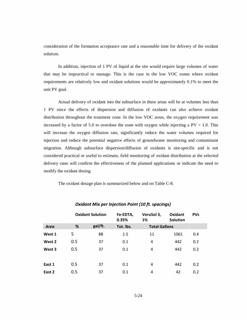
The oxidant dosage plan is summarized below and on Table C-8.
Oxidant Mix per Injection Point (10 ft. spacings)
Oxidant Solution Fe‐EDTA, 0.35%
VeruSol 3, 1%
Oxidant Solution
PVs
Area % gal/ft. Tot. lbs. Total Gallons
West 1 5 88 1.5 11 1061 0.4
West 2 0.5 37 0.1 4 442 0.2
West 3 0.5 37 0.1 4 442 0.2
East 1 0.5 37 0.1 4 442 0.2
East 2 0.5 37 0.1 4 42 0.2

5-25
Oxidant Mix per Infiltration Area‐ Vadose Zone
Oxidant Solution Fe‐EDTA, 0.35%
VeruSol 3, 1%
Oxidant Solution
PVs
Area % gal/sq. ft./ft. Tot. lbs. Total Gallons
West 1 20 2.1 105 181 18063 0.95
West 2 20 2.1 126 217 21676 0.95
West 3 groundwater‐injection only
East 1 0.5
1.7 0.6 44 4420 0.76
East 2 groundwater‐injection only
5.7.1.7 Groundwater Injection
Injection is proposed for the shallow groundwater zones in the east and west treatment
areas. Injections are proposed to be performed first, prior to infiltration (see Section 5.7.1.2).
Depth of injection will range from approximately 4 to 14 feet below ground surface (BGS),
depending on the depth of the clayey-silt confining layer. Nominal injection spacing is 10 foot
centers. Injection by direct-push drilling equipment is preferred. Any changes to the oxidant
injection plan as a result of field pre-injection testing or other field changes shall be as approved
and directed by URS. Oxidant injection dosages are described in Section 5.6.1 6, and the planned
injection areas are shown on Drawing C-3.
Some of the injections will require access to onsite building interiors (metal building on
Blackstone Ave). URS will coordinate with the property owner and tenants to obtain access to the
buildings and have manufacturing equipment and materials moved as needed to allow equipment
access. Existing vehicle entry doors on the buildings have free-openings as follows:

5-26
General criteria for injections are as follows:
Prior to injection, any surface/overhead utilities or obstructions and any
underground utilities/piping shall be identified. Surface pavement shall be pre-
cored prior to injections to achieve a clean hole for future repair, if the injection
point is not within a planned infiltration zone.
Each injection point shall be uniquely identified, and each injection point shall
have an Injection Log form that contains the following information: injection
number, date/time, oxidant dosage, oxidant flow rate and volume, injection
pressure at injection drive-head pipe,
The required oxidant dosages shall be pre-mixed in batches prior to injection.
The activators should not be added to the injection mix until the oxidant solution
is thoroughly mixed. A batch tank with a mixer is recommended for preparing
the required volume of oxidant for each injection point. The nominal batch tank
size required would be a minimum 1000 gallons based on the maximum oxidant
solution volume estimated for any single injection point as outlined in the
proposed injection plan (Table C-8, West Area 1). The batches may also be
mixed in smaller proportions (500-1000 gal) if necessary to facilitate field
operations. All oxidant batches shall be mixed for at least 5 minutes prior to
injection to assure a homogeneous mixture. Mixed oxidant batches shall be used
up on a daily basis.
Injections shall be on nominal 10 foot centers spacing. The spacing may be
modified based on the results of the pre-work injection testing (Section 5.6).
Single or multiple injection points may be employed at one time. If multiple
injection points are used, a manifold piping system may be used for oxidant
delivery.

5-27
Injections shall be performed from the bottom of the zone first, working towards
the upper part of the zone of treatment. Injections may be delivered on 1-foot
intervals or continuously to achieve a uniform oxidant dosage across the
treatment zone vertical interval, depending on the injection rod configuration and
the results of the pre-work injection testing.
Injection activities shall be done prior to vadose zone infiltration delivery
(Section 5.7.1.8). Treatment area perimeter injections shall be performed first.
Injections shall be staggered so as not to inject next to a point that was injected
immediately prior.
Injection pressures shall be within the guidelines described in Section 5.6.1.2
and they shall not be excessive as to cause soil or pavement uplift, or excessive
breakthrough of injected oxidant. Injection pressure shall be monitored
continuously during injection operations. Uniform oxidant flow rate shall be
maintained, if practicable without generating excessive back pressure in the
injection pipe or formation.
Existing monitoring wells and piezometers in and near the treatment zone shall
be monitored daily for water levels. Wells or piezometers closest to the injection
point shall be monitored more frequently during injection to check water levels.
See Section 5.10 for specific monitoring requirements.
Completed injection borings shall be backfilled and sealed immediately after
injection of the specified volume of oxidant. The injection zone interval shall be
backfilled with a clean sand, if possible.. Above the treatment zone the boring
shall be grouted with a Portland cement-bentonite grout mixture to the ground
surface.
5-28
5.7.1.8 Infiltration Beds
Infiltration is proposed for the vadose zones in the east and west treatment areas. Open
infiltration beds or trenches will be used to deliver the higher concentration oxidants to the high
VOC concentration vadose zones. Infiltration of oxidant solutions shall be by open shallow
pits/trenches above the vadose zone VOC areas. No liners are planned. Removal of surface
pavements will be necessary in the east treatment zone. Depth of the infiltration bed will range
from approximately 2 feet BGS. The infiltration bed area may be the entire treatment zone, or
subsections, depending on the Contractor’s work strategy and management of onsite traffic and
equipment. At a minimum, the West 2 Area should be implemented prior to the West 1 Area to
allow access to the Master Machine Building by their employees during treatment of the West 2
Area. None of the proposed infiltration treatment areas will require access to building interiors.
Any changes to the oxidant injection plan as a result of field pre-work infiltration testing or other
field changes shall be as approved and directed by URS. Oxidant infiltration bed dosages are
described in Section 5.6.1. 6 and planned infiltration areas are shown on Drawing C-3.
General criteria for infiltration are as follows:
Prior to constructing the infiltration beds, any surface/overhead utilities or
obstructions and any underground utilities/piping shall be identified. Surface
pavement shall be removed from the infiltration area and removed from the site
for offsite disposal in accordance with NYDEC and City of Jamestown
requirements.
The infiltration beds shall be excavated to a nominal depth of 2 feet BGS. The
finished bed floors shall be level. Excavation spoils may be temporarily stored
onsite for later backfill into the infiltration bed after treatment. The infiltration
beds may be the entire treatment zone area, approximately 5000 sf in the west
area, or they may be subareas of the treatment zones.
The perimeter of the bed excavations shall be secured with temporary
construction fencing to prevent onsite worker access or other visitor access.
5-29
Surface runoff into the beds shall be minimized by ditches and/or barriers.
Each infiltration bed shall be uniquely identified and have an Infiltration Bed Log
that contains the following information: infiltration bed number, date/time,
oxidant dosage, oxidant flow rate and volume, and bed liquid depths over time,
The required oxidant dosages shall be pre-mixed in batches prior to placement in
the infiltration bed. Multiple batches are anticipated for each infiltration area
based on the total volume requirements of up to about 22,000 gallons of oxidant
solution per area (Table C-8, West 2 Area). The activator should not be added to
the mix until the oxidant solution is thoroughly mixed. A batch tank with a mixer
is recommended for preparing the required volume of oxidant for each injection
point. All oxidant batches shall be mixed for at least 5 minutes prior to bed
placement to assure a homogeneous mixture. Mixed oxidant batches shall be
used up on a daily basis.
Mixed oxidant shall be placed uniformly over the entire infiltration bed by
spraying or flooding, depending on the volume of oxidant solution, the bed area,
and the infiltration rate. The maximum liquid level in any of the beds is expected
to be 1 ft. or less based on the proposed oxidant delivery plan. The largest beds,
West 1 & 2, have a total surface area of approximately 4700 sf, and a design
oxidant solution volume of approximately 40,000 gallons. Maximum liquid depth
at total volume would be approximately 13.5 inches.
Existing monitoring wells and piezometers in and near the treatment zone shall
be monitored daily for water levels. Wells or piezometers closest to the
infiltration area shall be monitored frequently to check water levels. See Section
5.10 for specific performance monitoring requirements.
After infiltration of the oxidant solution the beds shall be flushed with clean
water. A minimum water volume of 20% of the oxidant volume shall be applied.
Flush volumes are as follows:

5-30
Oxidant Solution Clean Water Flush
Area Gallons Gallons
West 1 18063 3600
West 2 21676 4300
East 1 4410 880
Treated infiltration beds shall be backfilled immediately after the total required
oxidant volume has infiltrated into the subsurface and the bed surface is
relatively dry. Onsite clean spoil materials previously removed from the area or
clean imported fill will be used for backfill of the beds.
In areas of previous pavement, a minimum of 8-inches of bituminous asphalt
pavement shall be placed. The pavement subbase fill shall be placed in 1 ft. thick lifts and
shall be compacted by a minimum 4 passes of a vibratory roller with a minimum 3500
lbs. dynamic force. In areas of previous vegetation (East), the backfilled area shall be
vegetated with a suitable grass mixture. See Drawing C-4 Site Closure Plan. The
schedule for backfill and paving of infiltration areas will be as directed by URS based on
the results of post-treatment monitoring.
5.7.2 Process and Equipment Requirements
In general, the majority of the necessary project equipment needed will be associated
with processing and injection of oxidants. Infiltration delivery of oxidants will require oxidant
batch processing and delivery of the oxidant into excavated beds or trenches. In-line continuous
mixing of oxidant solutions may be employed as an alternative approach, if these systems can be
demonstrated by the Contractor to meet the design requirements for the project. The selected
Contractor will propose specific equipment for the project which will be reviewed and approved
by URS prior to commencement of the work.
5-31
5.7.2.1 Oxidant Processing Equipment
Oxidant processing will require multiple onsite storage tanks, mixing tanks, a bulk
material handling system and pumping systems to prepare and deliver the oxidant solution to the
treatment zone. All of the materials of construction shall be compatible with the oxidant and
associated reagents.
Storage- Dry reagents such as sodium persulfate, surfactants and iron-EDTA
activators shall be stored in a secured dry condition, at a minimum on a dry
pad/base with a waterproof covering.
Water- ISCO processing will require significant volumes of water. For1 PV over
the treatment zone, 415,000 gallons of water will be required. Less water will
actually be needed since the current oxidant delivery plan proposes < 1 PV
volume of oxidant solution. See Section 5.7.1.6. The water volume based on the
current oxidant delivery plan is approximately 115,000 gallons. Additional water
will be needed for infiltration bed flushing and other site uses. These other
volumes are not estimated herein.
Onsite storage of the total project water supply volume is not practical. Onsite
storage of a minimum volume of water to supply 2 days of injection operations
will be required. The source of water will be determined by the Contractor. City
of Jamestown water lines are present on Blackstone Avenue. A fire water hydrant
is located on the north side of the street, directly southeast of the metal hut
building. The Contractor shall verify the availability of City of Jamestown water
prior to commencing work.
Mixing equipment will be needed to blend the dry oxidant and activator reagents
with water. The mix tank shall be of sufficient volume to allow batching of a
minimum volume needed for a single injection point. At a nominal 10-ft spacing,
this volume is estimated to be up to 1061 gallons (Table C-8). The mixer shall be
5-32
a high-shear unit capable of completely blending the dry oxidants and activators
into a uniform, non-flocculated solution.
The mix tank shall be placed within a secondary containment system capable of
collecting and storing the mix tank volume in the event of a tank leak, spill or
breach of piping.
Materials Handling Methods- Preparation of oxidant solutions will require bulk
feeding of dry products into mixing vessels. Mechanical or heavy equipment
transfer of bulk oxidant to conveyance systems or directly to mixing vessels is
anticipated. The mix proportions shall be accurately measured and controlled to
achieve the desired oxidant solutions for delivery to each treatment zone. All
oxidant and reagent mixing systems shall be placed within secondary
containment structures. The Contractor will propose specific materials handling
methods in the Contractor’s Field Operations Work Plan submittal.
Pumping Systems- A pumping system is required to transfer the mixed oxidant
solution to the treatment areas. Since the areas include infiltration beds and
injection points, the pumping requirements will vary. Injection pressures are
limited by the shallow depth of the treatment zone and low pressure/high volume
pump is more suitable for this application. Diaphragm and/or bladder pumps are
acceptable for injection. Transfer of oxidants to the larger area and volume
treatment beds may be accomplished by higher pressure pumping systems, such
as positive displacement pumps. Delivery of oxidant to infiltration areas will be
by open outfalls or spraying across the infiltration bed.
Monitoring – Sufficient gauging equipment shall be installed to measure oxidant
solution flow, transfer line and injection point pressures, injection and infiltration
volume/time and oxidant solution temperatures. These data shall be measured
and recorded on a Daily Log by the Contractor.

5-33
5.7.2.2 Injection Equipment
Injection by direct-push (DP) drilling equipment is preferred. These rigs provide greater
flexibility for site access and mobility and they are capable of injecting the volumes of oxidant to
the required depths of the site treatment zones. General requirements for the DP equipment are as
follows:
DP rigs shall be in good working condition and hydraulic lines shall be checked
and replaced as needed prior to the start of work. Multiple rigs may be used on
the project. Manifold systems shall each have multiple pressure gages and flow
meters to allow measurement of injected solutions at each point.
Drilling/injection rods shall be steel with threaded joints. All joints will have O-
rings that are compatible with the injected fluids.
Injection points may be slotted, retractable or pressure-activated, or a
combination of these. The injection point shall be able to deliver oxidant in a 360
degree distribution within the borehole. Expendable tips with open ended rods
are acceptable. The Contractor shall submit injection rod details for approval.
5.8 Cleanup and Site Restoration
Construction debris, waste materials, packaging material and miscellaneous solid wastes
shall be removed from the work site on a daily basis. Any dirt or mud that is tracked onto paved
or surfaced roadways shall be cleaned daily. Stored material shall be neatly stacked when stored.
Upon completion of the project and after removal of materials and equipment, the areas
used by the Contractor for storage of equipment or materials, and transporting equipment and/or
materials between work areas, shall be restored to original or better condition.
Any infiltration areas that had pavement removed shall be paved with bituminous
concrete as described in Section 5.7.1.8. URS will direct the Contractor on the schedule for final

5-34
paving based on the results of the performance monitoring. Disturbed vegetation areas shall be
graded to a smooth condition and re-seeded. See Drawing C-5 Site Closure Plan.
5.9 Demobilization
Following completion of the remedial activities and acceptance of the work by the
NYSDEC and Dow, the Contractor will remove all equipment, materials, supplies, debris/waste
generated by Contractor’s activities, temporary utilities and facilities, and manpower from the
Site.
The areas of the Site utilized and/or disturbed by the Contractor during the project are to
be left in a condition equal to, or better, than when the Contractor mobilized to the site.
5.10 Performance Monitoring
URS will conduct performance monitoring to monitor the site operations and evaluate the
effectiveness of the insitu treatment. Monitoring will involve hydraulic and chemical
measurements before, during and after the ISCO operations. The baseline pre-work sampling
described in Section 5.5 is not included as part of the monitoring described herein. Performance
monitoring is summarized on Table 5-1 and Drawing C-5 Site Monitoring Plan.
5.11 Field Modifications
Field modifications shall be managed in accordance with the construction quality
assurance and control plan (CQACP) as prepared by the Contractor in accordance with this
RAWP and as approved by URS.
Major changes to the scope of the ISCO operations as defined in the CQACP will require
NYDEC review and approval. Minor changes to the operations will be approved by Essex/URS.
All field changes will be documented per the CQACP. See Section 6.0.

6-1
6.0 QUALITY CONTROL AND ASSURANCE
The Contractor is responsible for quality control and shall establish and maintain an
effective quality control system monitored by URS. The quality control system shall consist of
plans, procedures, and organization necessary to produce an end product that complies with the
contract requirements. The system shall cover all construction operations and shall be keyed to
the proposed construct schedule. The work shall conform to the documents approved for
construction including all work plans and drawings.
The Contractor and its subcontractors shall comply with the construction documents
prepared by URS and the HASP prepared by the Contractor. The Contractor is responsible for
providing quality control during all phases of work. URS is responsible for quality assurance.
Changes significantly affecting the approved construction documents or project schedule
shall be brought to the prompt attention of URS. Work found to be out of compliance with
approved construction documents will be reviewed and halted, if necessary, until satisfactory
resolution acceptable to URS is achieved.
The Contractors construction quality assurance and control plan (CQACP) shall be
described in their Field Operations Work Plan (FOWP) submittal.
6.1 Responsibilities
The principal organizations involved in implementing the remediation at the site include
NYSDEC, ESP (Dow Chemical), URS, and the Contractor. Specific responsibilities and
authorities are delineated below to establish the lines of communications required to produce an
effective decision-making process during execution of the work.
6.1.1 Regulatory Agency
The lead regulatory agency involved with this project is the NYSDEC. In this capacity,
the NYSDEC will review construction documents for conformance with applicable requirements.

6-2
The NYSDEC has the authority to review and accept design revisions or requests for variances
that are submitted after the construction documents have been approved.
6.1.2 Essex Specialty Products Inc.
Essex Specialty Products Inc. (ESP), a former subsidiary of The Dow Chemical
Company (Dow), as owner, will be responsible for the proper permitting, design, and
construction of the project. ESP has retained URS as the project engineer and to confirm quality
assurance. The Contractor will be placed under contract with URS following approval of the
construction documents. ESP has the authority to dismiss all non-regulatory organizations
involved in the design, quality control and assurance, and construction of the items and activities
outlined in this RAWP.
6.1.3 URS
URS will function as Project Engineer and will provide construction quality assurance
personnel. URS’ responsibilities under these separate functions are defined below.
6.1.3.1 Project Engineer
As the Project Engineer, URS’ primary responsibility will be to provide engineering
technical support and QA oversight during ISCO implementation. In this capacity, URS will be
responsible for the monitoring of construction work and providing the Contractor with feedback
from questions regarding the RAWP. In addition, URS will be responsible for identifying,
documenting and correcting any deviations, as necessary, and to request and receive NYSDEC
approvals as may be required.
URS has the responsibility to review proposed design revisions associated with field
changes that deviate from the RAWP, and the authority to approve the revisions, and submit the
proposed revisions to Dow and the NYSDEC for approval. All field changes will be processed in
accordance with established procedures outlined in Section 6.3.

6-3
6.1.3.2 Construction Quality Assurance Inspector
URS will provide Construction Quality Assurance (CQA) during implementation of the
remediation activities. The CQA inspector has the responsibility and authority to halt work that is
not in conformance with the NYDEC-approved RAWP. The CQA inspector’s responsibilities
include:
Review Contractor Field Operations Work Plan (FOWP) for clarity and
completeness so that the work can be implemented correctly in a timely fashion.
Perform on-site inspections to ensure compliance with FOWP.
Verify that air monitoring activities have been properly completed and
documented.
Document the results of all inspection, test, and monitoring activities.
Report non-conforming conditions in accordance with the procedures explained
in Section 6.4, as well as other deviations from the FOWP to the Owner and
NYSDEC.
Verify the implementation of any corrective action measures.
6.1.4 Contractor
The Contractor’s responsibility is to perform the work in accordance with the FOWP.
Construction personnel will coordinate their work with the URS CQA inspector.
6.2 Site Meetings
Periodic CQA meetings will be held during implementation and construction. It is
anticipated that one meeting will be held each week for the duration of the project, unless
otherwise approved by the Engineer. Additional meetings will be held, if warranted during the
project. As availability allows, meeting attendees will include the URS Project Manager, the
6-4
CQA inspector, and the Contractor. Representatives of the NYSDEC and Dow may also attend,
as necessary, and timely notice of any meetings shall be distributed by URS.
The initial CQA meeting will be conducted on-site prior to initiating work. Subjects
proposed to be covered during this meeting include:
Providing appropriate parties with the NYSDEC-approved RAWP and project
FOWP and CHASP.
Resolving identified conflicts within the FOWP.
Reviewing the procedures and requirements for the tests and inspections to be
performed.
Reviewing methods for documenting and reporting inspection and monitoring
data (e.g. appropriate field book entries).
Reviewing procedures for identifying and correcting deviations.
Reviewing the HASP as needed.
Conducting a site walkover to review and discuss work issues.
Discussing the overall project schedule.
6.3 Daily Construction Quality Assurance
On a daily basis the CQA inspector will communicate with the Project Engineer (URS) to
discuss project activities. Discussion topics will include:
Previous activities and progress.
Planned activities.
Anticipated or potential construction issues.
6-5
Review of testing procedures, submittals, or inspection activities.
The CQA inspector will document the daily progress and activities. The documentation
will be utilized in preparation of the Remedial Action Report at completion of the project.
Specific inspection items will be outlined in the Contractors CQACP and will include,
but are not limited to, the following:
General work zone and treatment area layouts
Chemical manufacturer’s spec sheets and submittal data
Onsite chemical storage and security
Site water source verification
Oxidant solution preparation, mixing and delivery
Oxidant solution sampling and testing
Instrumentation calibration
Groundwater hydraulic monitoring during oxidant application
Offsite migration of dusts, particulates or vapors
Waste and debris management
Final site cleanup and restoration, including grading, pavement and vegetation
replacement and final surface drainage.
6.4 Field Change Request Process
The purpose of this procedure is to describe the method for requesting acceptance for the
implementation of field changes to the Work Plan and procedures applicable to the remedial
action.

6-6
A Field Change Request (FCR) is a document used to request and acquire the necessary
reviews and acceptance for implementing a field change involving design, process, or method.
During the course of field activities, conditions may be encountered that necessitate a change in
requirements affecting design, processes, or methods.
These changes may be necessary to correct or revise a design, institute use of additional
requirement, or request approval for relief from an existing requirement with suitable
justification. Field changes may also be requested to address and acquire guidance for unforeseen
or unanticipated conditions, or to acquire acceptance for alternate methods or processes to be
employed. A FCR form that includes a complete description of the requested change, seeks the
necessary acceptance, and provides for disposition of the request and identifies affected
documents is to be used for each proposed change.
6.5 Nonconformance Reporting
The purpose of this procedure is to establish and provide a system for identifying,
reporting, evaluating nonconforming items to prevent their inadvertent use or installation. This
procedure applies to permanent installations and items of hardware or materials, which are
procured, constructed, installed, or used in conjunction with remedial activities. This procedure
does not apply to expendable tools, supplies, or temporary equipment, items or materials. A
nonconformance is a deficiency in characteristic, documentation, or procedure that renders the
quality of an item or material unacceptable or indeterminate.
The CQA inspector initiating the Nonconformance Report will provide a detailed
description of the nonconforming condition(s), including any reference(s) to drawings, work
plans, specifications, or procedures which may provide acceptance criteria for the item or
material being reported. The CQA inspector, will maintain a log of NCRs.
If the NCR prompts any change to the intent of the construction documents, NYDEC
must approve of the change prior to implementation.

6-7
6.6 Project Closeout
Near the end of field activities work, URS will schedule a Site walk through with the
Contractor, and ESP/Dow personnel. Any remaining work necessary to satisfy the intent of the
RAWP will be identified and documented for follow-up action.
A draft Final Remedial Action Report will be prepared to include a description of
activities conducted to comply with the requirements of this RAWP and the Contractors FOWP.
Based on input from the NYDEC, the report will be finalized.

7.0 SCHEDULE
A general sequence of events is presented in this section. The Contractor will submit a
detailed construction schedule that outlines project tasks, sequences and durations. The final
project schedule will be approved by ESP/URS and be provided to NYDEC.
The general implementation schedule is as follows:
Submittal of draft RAWP (URS)
Baseline groundwater sampling (URS)
NYDEC review and comment on RAWP
RAWP revisions (URS) and final approval by NYDEC, as necessary
Issuance of UIC Permit from USEPA
Preparation of final project documents and bid package (URS)
Notice of Award of project to selected Contractor (URS)
Issuance of Subcontract/Work Order to perform project (URS)
Submittal of project documents (Contractor)
Approval of project documents and schedule (URS)
Issuance of Notice to Proceed (URS)
Pre-operations monitoring (URS)
Mobilization of materials and equipment (Contractor)
Site preparation activities (Contractor)
New monitoring well (3) construction (URS)
7-1

7-2
Groundwater ISCO Injection (Contractor)
Vadose zone ISCO Infiltration (Contractor)
CQA and operations monitoring (URS)
Bituminous pavement replacement (Contractor)
Final site grading and vegetation (Contractor)
Site final walk-through (all parties)
Demobilization and cleanup (Contractor)
Project Completion Report (URS)
Post-operations monitoring (URS)

TABLES

URS Corporation Essex Jamestown SiteUST Area ISCO
Soil VOC Data Summary
Table 3-1
2003‐2005 Data, mg/kgArea Sample
Depth
Date
Ft BGS Range Mean Range Mean Range Mean Range Mean Range Mean Range Mean
4 to 8 Nov, 2003 0.05-547 181.47 0.02-547 181.44 BDL-3.7 1.1 BDL-3.3 0.62 BDL-40 10.4 BDL-500 169
4 to 8 2005 403-2436 1000 339-2436 999.2 3.4-5.9 4.5 2.3-660 116 10-250 94.8 373-1520 751
4 to 8 Nov, 2003 0.11-0.41 0.26 0.03-0.36 0.2 BDL BDL BDL-0.013
0.009 0.007-0.063
0.035 0.026-0.284
0.155
4 to 8 2005 BDL-29.47 4.7 BDL-29.47 4.7 BDL-1.2 0.27 BDL-0.27 0.063 BDL-3.0 0.46 BDL-25 3.9
8 to 12 Nov, 2003 0.53-93.8 28.7 0.53-93.8 28.7 BDL-6.1 1.32 BDL BDL BDL-15 4.8 0.53-72.7 22.4
Notes:1. BDL values entered as 5 ug/kg in calculation for arithmetic mean
UST West
UST East
Soil VOC Summary
Total VOCs Total CTEX Cumene Toluene Ethylbenzene Total Xylenes
6/10/2011
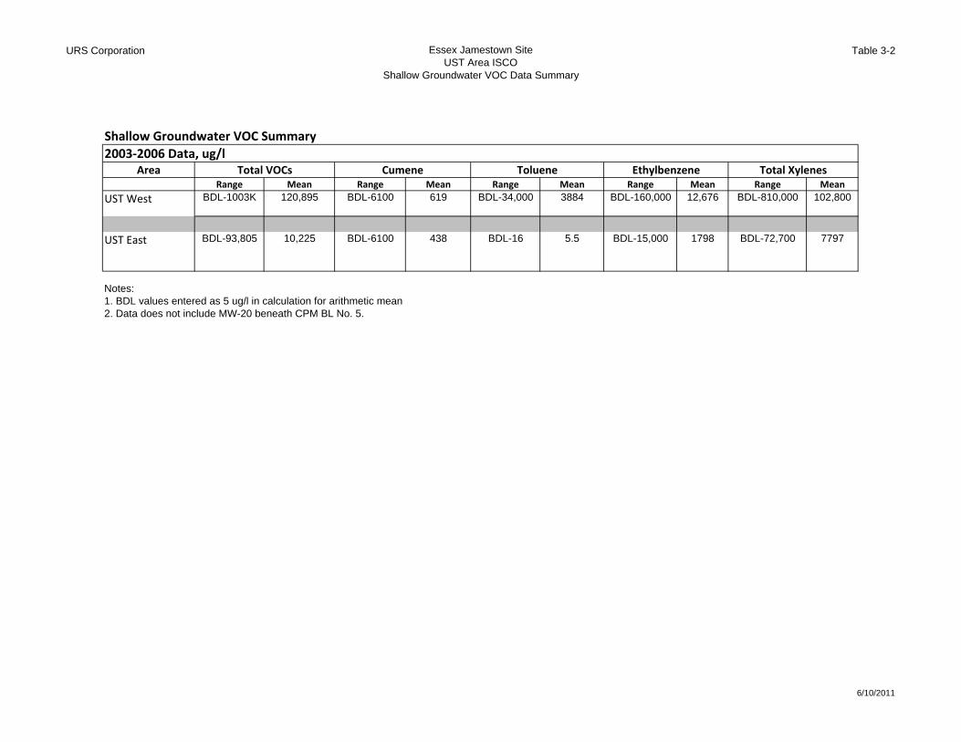
URS Corporation Essex Jamestown SiteUST Area ISCO
Shallow Groundwater VOC Data Summary
Table 3-2
2003‐2006 Data, ug/lArea
Range Mean Range Mean Range Mean Range Mean Range Mean
UST West BDL-1003K 120,895 BDL-6100 619 BDL-34,000 3884 BDL-160,000 12,676 BDL-810,000 102,800
UST East BDL-93,805 10,225 BDL-6100 438 BDL-16 5.5 BDL-15,000 1798 BDL-72,700 7797
Notes:1. BDL values entered as 5 ug/l in calculation for arithmetic mean2. Data does not include MW-20 beneath CPM BL No. 5.
Shallow Groundwater VOC Summary
Total VOCs Total XylenesCumene Toluene Ethylbenzene
6/10/2011

URS Corporation Essex Jamestown SiteUST Area ISCO
ISCO Performance Monitoring Summary
Table 5-1
Work Phase Objective Monitoring Locations Parameters FrequencyPre-Operations Measure Groundwater Levels
and Water Quality Indicators and VOCs to establish baseline conditions.
Wells- HW-9, MWs- 20, 23S, 24S, 26S, 27S and 28S, and PZ-5S
VOCs (EPA 8260), pH, cond, ORP, DO, sulfate, alkalinity, iron, and water levels
Within 2 weeks prior to the start of site oxidant applications
Operations Measure Groundwater Levels, Water Quality Indicators and VOCs to assess ongoing operations and short-term effects of ISCO.
Wells- HW-9, MWs- 20, 23S, 24S, 26S, 27S and 28S, and PZ-5S (use selected monitoring wells closest to weekly ISCO activities)
VOCs (EPA 8260), pH, cond, ORP, DO, sulfate, alkalinity, iron, and water levels
Chemical Parameters- Weekly during oxidant application periods. Well water levels- daily and increased to 2x/day min. for wells < 50 ft from injection points.
Post-Operations Groundwater- Measure Well Water Levels, Water Quality Indicators and VOCs to evaluate ISCO performance. Soils- Measure soil organic constituents to evaluate ISCO performance.
Wells- HW-9, MWs- 20, 23S, 24S, 26S, 27S and 28S, and PZ-5S. Soils- Continuous samples, 4 ft to water table. Select sample based on VOC headspace (HS) result. Sample vadose soils in west treatment area on 20 ft center grid and in east treatment area at centerline (E-W) on 10 ft centers.
Groundwater- VOCs (EPA 8260), pH, cond, ORP, DO, sulfate, alkalinity, iron and water levels. Soils- Field HS, VOCs and TPH.
Wells- Quarterly for 1-year after the end of site operations monitoring. Soils- 30 and 180 days after treatment
ISCO Performance Monitoring Summary
6/10/2011

FIGURES

, '
)
-i.! ~ ). 0 A' .: ~ \. ,, ' ]; <0 \ I
,
CONFlDENl1AL - ALL RIGITS RESER'oEll - PROPERlY <F
J
~i
ir~~~~~~~~
i , < C E '-
.I.ILW~~~~~~~~~II REFERENCE:!'> 4 0 2000 4000 BASE MAP IS A PORTION OF THE U.S.G.S. 7.5& -=-=-~!!!i!iii.':1 MINUTE TOPOGRAPHIC SERIES JAMESTOlNN, NYi!i: NEW YORK ~ QUADRANGLE. DATED: 1954, PHOTOREVISED:~ SCALE IN FEET 1979. SCALE: ,. = 2000', CONTOUR INTERVAL/' IS 10 FEET... QUADRANGLE LOCATlON
~ I-----.L-----"'T'"---....,.,==,.,..,==,.,."=,.",..,.,,.----!REMEDIAL ACTION WORK PLAN00 UST AREA CHEMICAL OXIDATION
!! URS ESSEX/HOPE SITE SITE LOCATION MAP JAMESTOWN, NY
g1 QJENT: ESSEX SPECIALTY PRODUCTS, INC. JOB NUIlIBER, 41568097
: L. ",,""',.;;;;.''''',.;;;'_";.;."""'-,.;;;,,,,";.,,"- ...."_"~_."-A"S;.;.S;.H..;;;O"W;.N__..,,:::","':::"':::"f,:;.. 1_-..;;;1 -",,'~'_'

REVo
JAMESTOWN, NY
JOB NUMBER: 41568097
2-1
/: ..=:::::::r,
'=:/
.. _ .. _1._ .. _ ..-..;.:..;:::;.:..:.;~
AVENUE
o
FIGURENUMBER
HOPKINS
METALBUILDING
FORMER PlANT 5
LOr
AS SHOWN
REMEDIAL ACTION WORK PLAN UST AREA CHEMICAL OXIDATIONGENERAL SITE PLAN
CLIENT: ESSEX SPECIALTY PRODUCTS, INC,
SCALE:
ESSEX/HOPE SITE
URS TREATMENTPLANT BUILDING
II
NPLI AREAII
-.J '00@VP.,. S
/
/
/
/
PITISBURGH. PENNSYLVANIA
oo
CONFIDENTIAL - ALL RIGHTS RESERVED - PROPERTY OF
,..,........._ .......~......""'""-....-""""'"/',.......,. . _ .. _ .. _ .. - .. - T _ .. _ .. - .. _ .. _ .. •~~':":'":l~~':":':::::':':~~~"::::':":".::~~:\.,..~"'-...::MAP Uhlns (lYP.) SEEMAP NOTES 1 • Ji
LOr
BLACKSTaIIE AVENUE
a 60 120
~~N~FE:E:T~~I
LEGEND
---- PROPERTY LINE
..-@ PHOTO ID AND DIRECTION
f==--------------------------------
lIJ II FORMER ESSEX SPECIALlY PRODUCTS> AND ULLY INDUSTRIES. INC. FACILITIES°L ~~~~
~ U~:::.:-:-::::~-:-::::~-~-::::~::::::::::::::::~::·::r:::r:~:~·:::::::::::i~:-:-::::-:-::::-:-~~~:-:-:::!E:E~::c:I:+"::c:c:c:':c:.:':.:.~!:~~~~~~=:=========::~:~:~::::~:::~:::::l~t:r~~?:::~t~:~~~=-~~
I. NEIl GUIIIE • QJU) LIE: PROPERTY LINES AND MAPPING ADJACENT TO BIGELOW AVENUE, NORTH &: SOUTH OF HOPKINSAVENUE It EAST OF BIGELOW AVENUE, AND SOUTH OF BLACKSTONE AVENUE WERE TAKEN FRON II VARIET't' OF SOURCES INCUJDINGSEPIA W'tlAR SITE t.lAP (SEE REFERENCE 1), USGS 7.5 t.lIHUTE TOPOGRAPHIC MAP - JAt.lESTOWN, NY, CITY OF JAMESTOWN TAX MAPRECORDS, AND URS FIELD RECONAISSANCE. LOCATIONS AND DII.4ENSIONS IN THESE AREAS ARE APPROXIMATE.
2. VERTICAL BENCH MAAK INFORIIM110N CAME FROM U.S.G.S. Pl.JQUE U-88-S.E. ABUTT. ERIE R.R. BRIDGE OVER BUFFALO ST.,ElEV.- 1296.034 (NATIONAl... GEODETlC \/ERTICAL DATUM, 1929).HORIZONTAL COORDINAlES PROVIDED FOR THE MONITORING WELLS AND THE PROPERTY CORNERS ARE BASED ON A LOCAL GRIDESTABLISHED BY THE SURVEYOR. N10ooo. E10000 IS A PK NAIL SET IN THE CONCRETE CURB/GUTTER NolO IS PART OF THE ORIGINALTRAVERSE. IRON STAKES WERE SET AT THE PROPERTY CORNERS.
005511301111KKGG
I 1. Bf.SE MAPPING INCLUDING THE LOCAllONS OF SOME OF THE BUILDINGS, ROADS, CURBS!SIDEWAI.J(S, FENCING, PAVED AREAS, ALl~ UTIUTIES (UNDERGROUND UTILIlY LOCATIONS ARE APPROXIMATE), AND PROPERTY BOUNDARY WAS PROVIDED BY MICHAEL J. RODGERSS AND ASSOCIATES, LAND SURVEYORS, BEMUS POINT, NEW YORK, N.Y.S. UCENSE No. 49232. THE BASE MAP WAS A SEPIA HARD COP"( ATI A SCN-E OF 1·"'20', DATED APRIL 15. 1992, LAST REVISION DATE MARCH 10. 1993. RECCNERY WELLS. SPARGE WELLS. AND SVE WELLSti WERE SURVEYED AUGUST. 1997. MONITORING WELLS IN lHE VICINrTY OF lHE RENEDIAl. N:TION CONSTRUCTION WERE SURVEYED AUGUST,<, 1997, MONITORING WELLS MW-18, MW-21D,MW-22D, MW-2JS, MW-2JD, MW-24S, ALl.. RECOVERY WELLS (RW), ALL GEOPROBES (GP)
(EXCEPT GP-4S), ALl.. PIEZOMETERS (PZ), AND ALl.. VAPOR PROBES (VP) (EXCEPT VP-JS) WERE LOCATED BY URS FIELD SURVEYC5 AUGUST 2006. RW-6 PIPEUNE LOCATED BY FIELD MEASURENENTS ON 10/17/2008. RW-6, MW-25S AND MW-25D LOCATED BY URS~!1c FIELD SURVEY JUNE 30, 2009. COORDINATE INFORMATION SHOWN AT lHE BUILDING CORNERS CAME FROM lHE MICHAEL J. ROGERS
SURVEY DONE ON JANUARY 9. 1998. All. OTHER BUILDING CORNERS ARE APPROXIMATE. lHE SITE AREA BEYOND THE 1998 SURVEY WAS
::I ~~~~~S~U~~~~°:t:~~NciN~G~rRG~~IlUil~Hr;;:G~i~TOTH~RO~~E~~g:-~~H~m:Z~~=:~C~~A0'1'~Eeb COMPOSITE SURVEY t.W' ARE SHOWN ON THE DRAWING. SEE MAP REFERENCE J.
~
I.:J~
Il:I"..;;;=~";;;;'~~=;;';;;;'=~~=~';";';;;;=;';;"';';';;';';'~~ """' """' ...I-__-------_.......1...-.....

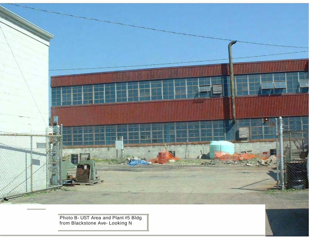
Photo B- UST Area and Plant #5 Bldgfrom Blackstone Ave- Looking N