remedial action master plan (ramp) · this remedial action master plan ... various types of...
TRANSCRIPT

REMEDIAL ACTION MASTER PLANFOR FACET ENTERPRISES SITE
Elaira Heights, NY
Work Assignment Z-l-12Under
Contract No. 68-03-1612
February 17, 1983
ByC.C. Johnson and Associates, Inc.
C300582*
cP
L
Irr
REMEDIAL ACTION MASTER PLANFOR
FACET ENTERPRISES
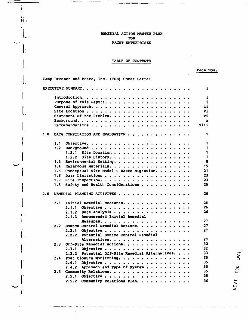
TABLE OF CONTENTS
Page Nos.
Camp Dresser and McKee, Inc. (COM) Cover Letter
EXECUTIVE SUMMARY. ....................... i
Introduction. ....................... iPurpose of this Report. .................. iGeneral Approach. ..................... iiSite Location ....................... viStatement of the Problem. ................. viBackground. ........................ xRecommendations ...................... xiii
1.0 DATA COMPILATION AND EVALUATION .............. 1
1.1 Objective. ...................... 11.2 Background ...................... 1
1.2.1 Site Location ................. 11.2.2 Site History. ................. 1
1.3 Environmental Setting. ................ 81.4 Hazardous Materials. ................. 151.5 Conceptual Site Model - Haste Migration. ....... 211.6 Data Limitations ................... 231.7 Site Inspection. ................... 231.8 Safety and Health Considerations ........... 25
2.0 REMEDIAL PLANNING ACTIVITES ................ 26
2.1 Initial Remedial Measures. ............... 262.1.1 Objective ................... 262.1.2 Data Analysis ................. 262.1.3 Recommended Initial Remedial
Measures. ................... 272.2 Source Control Remedial Actions. ........... 27
2.2.1 Objective ................... 272.2.2 Potential Source Control Remedial
Alternatives. ................. 282.3 Off-Site Remedial Actions. .............. 32
2.3.1 Objective ................... 322.3.2 Potential Off-Site Remedial Alternatives. ... 33 g
2.4 Post Closure Monitoring. ............... 35 Q2.4.1 Objective ................... 352.4.2 Approach and Type of System .......... 35 o
2.5 Community Relations. ................. 35 *_,2.5.1 Objective ................... 352.5.2 Community Relations Plan. ........... 36 <-•
00roen
'!
u.Page Nos.
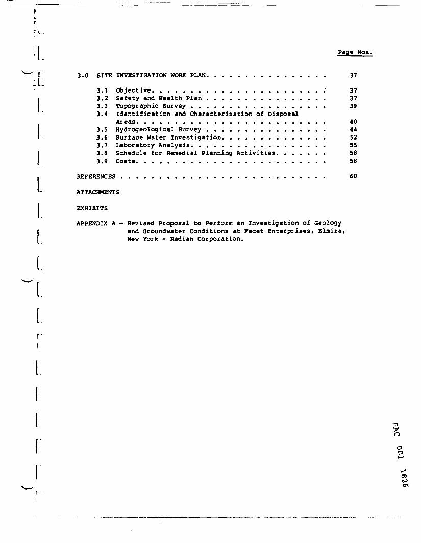
3.0 SITE INVESTIGATION WORK PLAN. ............... 37
3.1 Objective. ...................... 373.2 Safety and Health Plan ................ 373.3 Topographic Survey .................. 393.4 Identification and Characterization of Disposal
Areas. ........................ 403.5 Rydrogeological Survey ................ 443.6 Surface Water Investigation. ............. 523.7 Laboratory Analysis. ................. 553.8 Schedule for Remedial Planning Activities. ...... 563.9 Costs. ........................ 58
REFERENCES ........................... 60
ATTACHMENTS
EXHIBITS
APPENDIX A - Revised Proposal to Perform an Investigation of Geologyand Groundwater Conditions at Facet Enterprises, Elmira,New York - Radian Corporation.
L
rCO
r
'-1
I
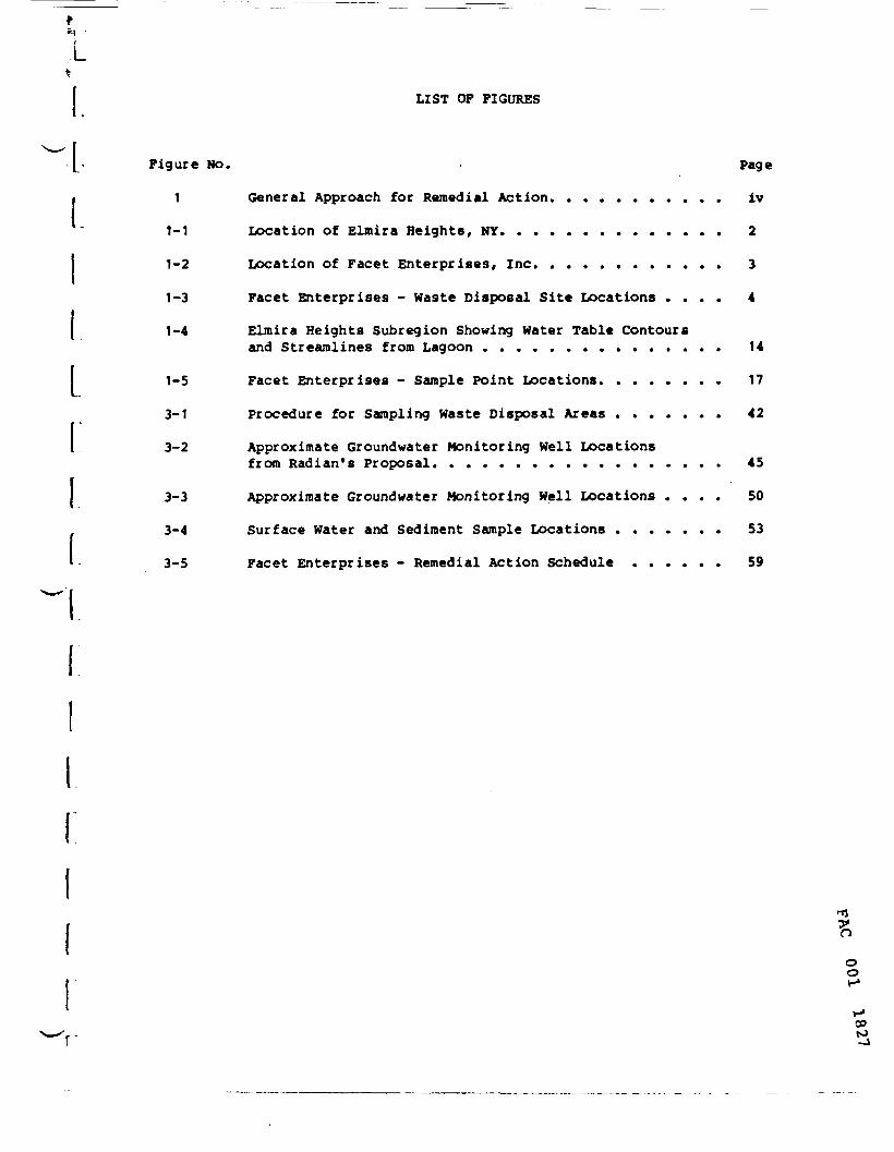
LIST OF FIGURES
Figure No. . Page
1 General Approach for Remedial Action. .......... iv
1-1 Location of Elmira Heights, NY. ............. 2
1-2 Location of Facet Enterprises, Inc. ........... 3
1-3 Facet Enterprises - Waste Disposal Site Locations .... 4
1-4 Elmira Heights Subregion Showing Water Table Contoursand Streamlines from Lagoon ............... 14
1-5 Facet Enterprises - Sample Point Locations. ....... 17
3-1 Procedure for Sampling Waste Disposal Areas ....... 42
3-2 Approximate Groundwater Monitoring Well Locationsfrom Radian's Proposal. ................. 45
3-3 Approximate Groundwater Monitoring Well Locations .... 50
3-4 Surface Water and Sediment Sample Locations ....... 53
3-5 Facet Enterprises - Remedial Action Schedule ...... 59
oo
CD

L
L
fCr
LIST OF TABLES
Table No. Page
1-1 Nells Producing within the Elmira Heights Subregion. ...... 13
1-2 Streamline Data, Elmira Heights Area .............. 13
1-3 Samples Collected at Facet Enterprises, Inc. ..........16
3-1 Priority Pollutants Proposed by Radian for Analysisin Core Samples Collected at the Facet Site. ..........47
3-2 RCRA Groundwater Analyses Proposed by Radian ..........48
3-3 Facet Enterprises Detailed Site Investigation -Samples Requiring Laboratory Analysis. .............56
ooo
00N>00

1»;LiL
LIST OF EXHIBITS
Exhibits
1-1 Chemung River Basin Aquifers
1-2 Surficial Geology - Newtown Creek Basin
1-3 Cross Sections - Newtown Creek Aquifer
1-4 Aquifer Thickness - Newtown Creek Aquifer
1-5 Potentiometric Surface - Newtown Creek Aquifer
1-6 Well Yield - Newtown Creek Aquifer
ooo
00N>
i.
LIST OF ATTACHMENTS
Attachment
A Facet Detailed Site Investigation - Consultant Direct Labor
B Facet Detailed Site Investigation - Other Direct Costs
ooo
00OJo
i
i
r
EXECUTIVE SUMMARY
Introduction
This Remedial Action Master Plan (RAMP) is prepared in accordancewith the proposed rules of the National Contingency Plan (NCP) (F.R. Vol.47 No. 49, March 12, 1982) originally published pursuant to Section 311 ofthe Federal Hater Pollution Control Act. Remedial actions are thoseresponses to releases on the National Priority List that require long-termand expensive efforts to prevent or mitigate the migration of a release ofhazardous substances. The specific aspects of remedial actions are pre-sented as Phase IV, Section 300.67 of the NCP. This RAMP will form thebasis of a scoping decision to be made by the EPA or the New York StateDepartment of Environmental Conservation (NYSDEC) as to the remedialinvestigations, feasibility studies and other on-site or off-site remedialactions particularly applicable to the hazardous waste sites discussedherein. The scoping decision allows the implementation of limited remedialactions, where the RAMP has identified such action as appropriate, in ashort time. It is anticipated that this RAMP will serve as the primaryplanning document for all remedial action activities at the site followingEPA Region and Headquarters review. The final version incorporating EPA'scomments is anticipated to form the basis of EPA - NY State cooperativeagreement.
Purpose of this Report
The purpose of this RAMP is to assemble and analyze existing data, toidentify the scope and sequence of remedial projects, and to present acomprehensive schedule for implementing remedial actions. The planaddresses the phasing requirements identified in the National ContingencyPlan and provides order of magnitude cost estimates for each project.A draft work statement for the first project to be initiated at each siteis included along with data limitations, community relations strategies,and identification of any special problems in project implementation.
oo
00u>

I!LL
^
L
L
General Approach
This RAMP is prepared from a review of existing relevant information.This includes research reports, and information from the files in the NewYork State Department of Environemntal Conservation, the New York StateDepartment of Health, the Chemung County Health Department and the Environ-mental Protection Agency. Based on this information, remedial actionmeasures are evaluated. The remainder of this section discusses thevarious types of remedial measures as set forth in the NCP.
There are three types of remedial actions identified in the NCPincluding:
o Initial Remedial Measureso Source Control Remedial Actionso Off-site Remedial Actions
Initial Remedial Measures are used when a significant threat topublic health, welfare or the environment is found to exist and when theproblems causing the threat have a straightforward solution available. Themeasures should be initiated before selection of a final remedy and must befeasible and cost-effective. Initial Remedial Measures require a minimumof planning, can be completed quickly and are consistent with the finalremedy. Examples of Initial Remedial Measures include: fencing of sitesfor security precautions, removal of hazardous waste in exposed drums thatpose a threat of fire or explosion, and construction of drainage ditches toprovide an effective drainage control system.
Source Control Remedial Actions are taken when substantial concentra-tions of hazardous substances remain on-site, barriers to retard migrationof hazardous substances are inadequate, and/or there is a serious threat topublic health, welfare, or the environment. Source Control RemedialActions are not appropriate if all hazardous substances have migrated fromthe area of original location or if the lead agency determines that thematerial cannot be adequately contained. An example of source controlremedial action is the removal of subsurface wastes that are contaminatinga drinking water supply.
oo
00U)
ii

*
I
I:
L
Off-site Remedial Actions are taken when Source Control RemedialActions are inappropriate or not effective in mitigating a significantthreat posed by the migration of hazardous substances from the site.Off-site Remedial Actions may include provision of permanent alternativewater supplies, management of a drinking water aquifer plume or treatmentof contaminated drinking water aquifers. Source Control and Off-siteRemedial Actions can proceed in parallel if appropriate.
The general approach for a remedial action investigation is presentedin Figure 1. The first step in the remedial action activities is tocompile the pertinent existing data on the site and to evaluate the datafor accuracy and completeness. One visit to the site is scheduled toverify existing data, observe first-hand the problem areas, and to meetwith the owner, if appropriate, or local representatives familiar with thehistory of the site. NO air, water, or soil samples are taken from thesite at this time. Limitations of the existing data are also identified.
The second step is to scope the appropriate remedial actions, ifthere is sufficient information. The scoping decision requires a detailedreview of existing data on the site background, environmental setting,hazardous material characterization, and data limitations. Based on thisreview, appropriate Initital Remedial Measures, Source Control and Off-siteRemedial Actions can be scoped in an effort to reduce a threat to thepublic health, welfare, or environment.
The most cost-effective Initial Remedial Measure is selected andimplemented with a minimum level of additional site investigation, feasi-bility study, and engineering design. After the Initital Remedial Measuresare complete, scoping of the next phases for action proceeds. Based on thescoping decision it may be necessary to initiate a remedial site investi-gation and feasibility study for Source Control and Off-site RemedialActions during which a limited number of alternatives are evaluated fortheir feasibility and cost-effectiveness.
2?noo
CD00co
iii

COLLECT AND EVALUATEEXISTING SITE DATA
OBTAINENFORCEMENT PLAN
FIGURE 1 APPROACH FOR
SITE REMEDIAL INVESTIGATION
PREPARE REMF.DIAL ACTIONMASTER PLAN (RAMP)
1 r
INITIAL REMEDIALMEASURES
^
IDENTIFY DATAREQUIREMENTS
l
CONDUCTREMEDIAL INV
FEASIBILtAND D
SCOP INCDECISION
^
SOURCE CONTROL[ REMEDIAL PLANNING
^
IS DATA ADEQUATETO PROPOSE REMEDIAL
ALTERNATIVES AND PERFORMFEASIBILITY STUDY?
-e. IDENTIFY ADDITIONALDATA REQUIREMENTS
1
LIMITEDESTICATION,TY STUDY:SICN
4
IMPLEMENTCOST EFFECT I VB
ALTERNATIVE
DEVELOP ANUMBER OF Al
1
LIMITEDTERNATIVES
rSCREEN
ALTERNATIVES
« ————— CONDUCTINVEST
^r
^ f
OFF -SITEREMEDIAL PLANNING
+
IS DATA ADEQUATETO PROPOSE REMEDIAL
ALTERNATIVES AND PERFORMFEASIBILITY STUDY?
1REMEDIALCATION
^DEVELOP A LIMITED
NUMBER OF ALTERNATIVES
^ t
SCREENALTERNATIVES
1 1
FEASIBILITY OFALTERNATIVES
1SELECT COST EFFECTIVE
ALTERNATIVES
FEASIBILITY OFALTERNATIVES
1
SELECT COST EFFECTIVEALTERNATIVES
too
DESIGN AND IMPLEMENT___ REMEDY______
DES ICN AND IMPLEMENTREMEDY.

\i\iiir.rr
In some situations, Off-site Remedial Actions may be necessary becausehazardous substances have migrated off the site or are not contained. Theneed for Off-Site Remedial Actions is often dependent on the outcome ofsite investigations and cannot be recommended without additional datacollection and analysis.
Post-closure monitoring is the last phase of the RAMP. This phaseis important because it closes the loop on the remedial action activitiesand provides a basis for judging the need for and the effectiveness ofremedial actions at a site. The post closure monitoring program is depen-dent on the remedial actions implemented and the potential for contaminantmigration from the site.
Critical to any RAMP is the early involvement of the affected commu-nity. A community relations strategy usually includes formation of anadvisory committee and organization of public meetings. The communityrelations plan is designed to involve the public in all stages of activi-ties associated with remedial actions contemplated.
Oo
00U)U1

i
i
r
Site Location
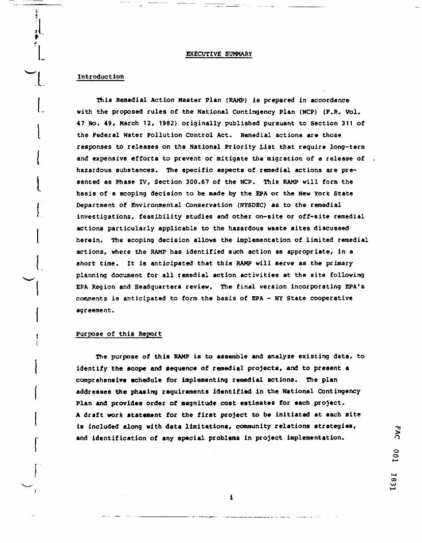
Facet Enterprises is located approximately 3/4 of a mile north ofthe city of Elmira in Chemung County, New York. The plant is situatedwest of Route 14 at 18th Street (see Figures 1-1 and 1-2).
Statement of the Problem
The Facet Enterprises hazardous waste site located in Chemung County,New York is listed on the US Environmental Protection Agency'sList of 418 top-priority disposal sites. The site is eligible for fundsunder the Comprehensive Environmental Response, Compensation, and Lia-bility Act (CERCLA) of 1980, known as "Superfund." Remedial actionsare subject to the requirements of State participation pursuant to Section104(c}(3) of CERCLA. Negotiations are anticipated between the DSEPA andthe current and past site owners over responsibility for cleanup activi-ties. Superfund monies may be used for a portion of the site cleanup.
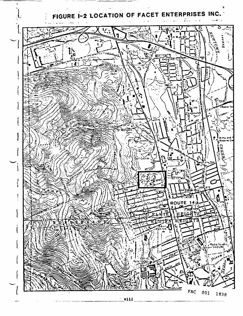
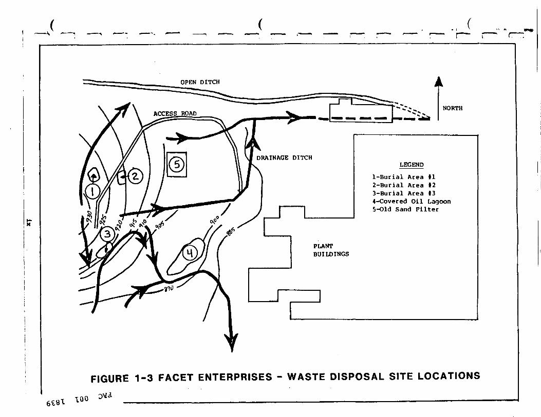
At the Facet site, the major environmental threat is a result ofimproper on-site disposal of plating waste, grinding waste, spent solvents,oil sludge and waste oil into 3 waste burial areas, a covered oil lagoon,and a sand filter which was also used as a sludge drying bed (see Figure1-3). Sampling investigations conducted at Facet have shown high levels ofa number of metals in all of the disposal areas as well as PCBs in thecovered oil lagoon. These uncontrolled hazardous wastes have contaminatedsurface and possibly groundwaters. Surface water from the Facet site wassampled from the two ditches which carry it to a nearby stream. Highlevels of TCE and other volatile organic compounds were detected in thesamples. In addition, sediment samples collected from the bottom of theseditches contained high concentrations of metals. Groundwater contaminationwith TCE has been detected at the Facet process water wells approximately2500 feet east of the site, and also at the Sullivan Street wells southeastof Facet. There are other potential sources of this aquifer contaminationin the area and the available information is inadequate for identifying £Ja specific source or sources. There is also a lack of information on
oo
00U)
vi
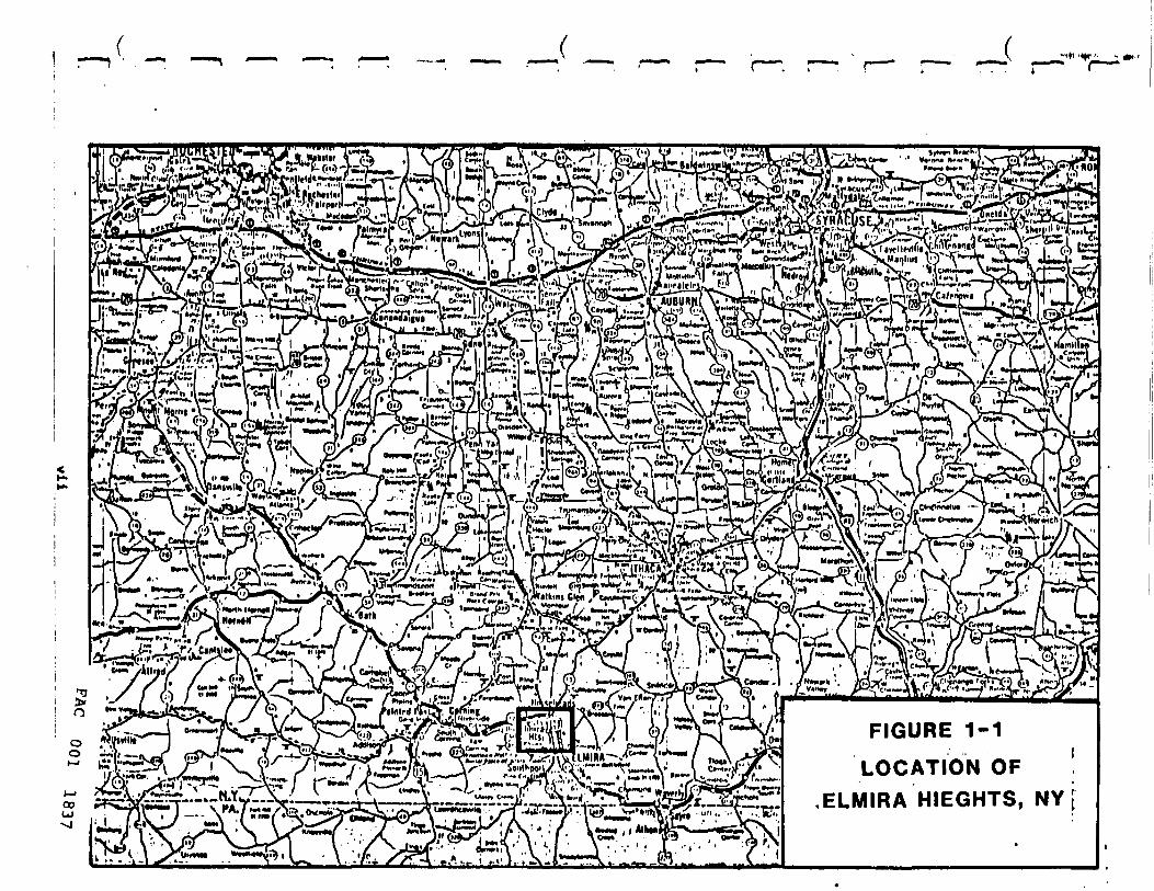
FIGURE 1-1
LOCATION OFELMIRA HIEGHTS, NY [
i FIGURE 1-2 LOCATION OF FACET ENTERPRISES INC
_-«••-' I —V u fri'te. ;^-^- I 0S rf*-.S»r**~ ~~*1 * « B _ -r*- "V.j j?^ei-^ . ^——
*%!/ \ ,iw \TI'WoTA.tStkA '•A *5jJ ^^** '.
OPEN DITCH
NORTH
LEGEND
1-Burial Area II2-Burial Area 123-Burial Area 134-Covered Oil Lagoon5-Old Sand Filter
FIGURE 1-3 FACET ENTERPRISES - WASTE DISPOSAL SITE LOCATIONS
ioo

I'*:(
I
the hydrogeology of the Facet site which compounds the problem. This RAMPaddresses the problem by carefully evaluating the available data anddeveloping a site investigation work plan for obtaining the necessaryinformation for remedial action planning.
Background
Facet Enterprises Motor Components Division is an active motorparts manufacturing firm occupying a 31 acre site. On-site disposalof metal wastes-liquids and sludges, oil wastes, solvent wastes and othermaterials-occurred from at least the 1940's to late 1978 or early 1979.NYSDEC documents indicate that the majority of the disposal was done bythe former plant owner, the Bendix Corporation. Facet Enterprises tookover the plant in 1976, and discontinued all on-site disposal except thatof metal hydroxide sludge from their industrial wastewater treatment plantto a sludge drying bed. This practice was discontinued in 1979. Exten-sive grading was done by Facet in 1979 as well as the construction ofditches to divert surface water around the waste disposal areas. Facili-ties were also constructed for the collection and treatment of leachatefrom the disposal areas. These actions were taken in compliance with aconsent decree entered into by Facet Enterprises and the New York StateDepartment of Environmental Conservation (NYSDEC).
The site consists of a relatively flat area containing the facility's30 buildings and an area with slopes of 5 to 10% rising to the west inwhich the disposal areas are located. These disposal areas include threesolid and liquid waste burial areas, one covered oil lagoon, and onecovered sand filter which was also used as a sand drying bed. All ofthese facilities are presently inactive. There is also a pond areawhich collects leachate from the solid and liquid disposal sites. Thisleachate is stabilized with lime and pumped into the plant's wastewatertreatment system. Wastes known to have been disposed on the Facet propertyinclude: cyanide salt heat treating waste, heavy metal sludge from awastewater treatment plant, zinc, nickel, cadmium, chromium, polymer «jcoagulating agents, chloride, sulfides, solvents and various quenching and Ocutting oils. oo
CP*»o

^^/i^m...., ...\*b&V-*rfrM#
. V .•<-\:-n '•"::;;?=- \ \\>/-•. U M>~- >.\
R S.OOfo52OOO
oo
00
POTEHTIQMCTtIC COHTOUR—lliov* apprOltMt* ll-tltude «t which v*t*r vould (tand In tightlycased w*lla. Contour tnttival 10 (cat.HatlonalCcod*ttc Vertical Da tun of HJ». Krrm Indl-catea direction of fround water Clou.
DOUNMIIY—daahed «l>ere lull e.tanl olaquiCer la not ahown
WELL STHBOLS
00414000 COWUNITT MATER stsrm WELL on HELL ritLD-I nunbeied by Hex York stata Department of Health
OATH POINTx
Ol OBSERVATION HELt—veil for which hydroqraph laahown, numbered by U.S. Ceoloflcal Survey
MAJOR INFLOW TO AO.UtrEB.--itrea« and aroundvatar(low alonf «aln valleya beyond entent of mappedaquifer
MAJOR OUTrUW PROM AOUIFCR—atrea* and oround-vater flow beyond extent of «pped aquifer
NOTE
The contouri repreaent the eatlmated averaqa altitude oftha water table In the aquifer baaed on aurface-water levelaand water lavela In limited wella meaaured In the period H)lto ltd with moat of the data from the late UiO'a and earlyIWO'a (Randall, l»'J and Relaenauer. 1*77). Hater levelahave not changed over the yeara other than aaaaonally. Thewaiir table fluctuatee aeaaonally In reaponae to recharge anddlacharqe. Recharge occur• generally over the entire aquiferwhereever the land aurface la permeable. Induced recharqefrom atreaaia occura where pumpinq wella cauae reveraed qra-dlenta. Olecharo/e occura principally aa Inflow to atreama andaa pumpaqe from wella. Seaaonal fluctuatlona are laaat along,•a)or atreama and lakea.
Fluctuation! ate repreaented by the hydroqraph of thaobaervatlon well cm 41 In the eaatern part of the aquifer. Thawater-level fluctuatlona are believed repreaentatIve of theaquifer for the period of record.
Sourca: MHIar at al. 1982
EXHIBIT 1-5
POTENTIOMETRIC SURFACE-
NEWTOWN CREEK AQUIFER
, I,(.
ri:
i;' I"
Facet site is located on the western boundary of the NewtownCreek aquifer which consists of outwash gravels and alluvial depositsextending fron north of Borseheads to eastern Elraira (see Exhibit 1-5) .Regional groundwater flow in the aquifer is generally fron northwestto southeast. Preliminary indications are that groundwater flow fromthe Facet site would be in an east-southeasterly direction becoming moresoutherly towards the Sullivan Street public water supply wells located inone of the most productive sections of the aquifer.
A high concentration of 44 ppb of TCE has been found in a FacetEnterprises well located 2500 feet east of the disposal areas. WhileFacet may be a contributor to this pollution, other sources upgradient ofthe well may also be partially or full contributory to it. Insufficientdata exists for a definitive answer.
•A public water supply well, the Kentucky Avenue Hell, is locatedabout one mile north (upgradient) of the plant site. This well is part ofa public water supply system which serves over 60,000 residents in Elmira,Elmira Heights, and Horseheads. The well is presently closed due tocontamination by trichloroethylene (TCE) . The exact source of the well'scontamination has not been definitely determined but is more likely to beupgradient sources rather than Facet. Two miles downgradient of the plantsite are the two Sullivan Street public water supply wells. Low levelcontamination with TCE has been detected in these wells. Facet may possi-bly be a contributor to this contamination. Groundwater modeling studiesin 1977 using the Chemung River Basin Groundwater Model have shown thatcontaminated flow from a lagoon probably located at the Facet site would bein the direction of the Sullivan Street Wells and affect 3 wells locatedabout two-thirds of the distance to the Sullivan Street Wells in 14 to 20years from entry into the aquifer.
In summary, the Newtown Creek aquifer is being contaminated by hazar-dous wastes which pose a threat to the public water supply as well asprivate wells. Facet Enterprises waste disposal sites as well as othersnorth of Facet may be contributors to this problem. Detailed site investi-gations are needed to define the problem, identify and characterize thewaste disposal sources, locate the contamination plume and determine theextent of the pollution prior to development of remedial action plans.
oo
00

Migration of pollutants from the Facet site by surface water routeshas been demonstrated. The persistence of the pollution off-site andits significance have not been determined. While this nay be a lesserhazard than the potential groundwater pollution, investigations are neces-sary to define the problem.
Recommendations
This RAMP recommends that no initial remedial measures be undertakenin view of those implemented by Facet Enterprises under the consent decreeof 1979. It also recommends that detailed site investigations be under-taken prior to the development of any Source Control or Off-site RemedialActions. A site investigation work plan has been presented together withcost estimates and a schedule. The site investigation work plan is com-prised of the following sections:
o Safety and Health Plano Topographic Surveyo Identification and Characterization of Disposal Areaso Hydrogeological Surveyo Surface Hater Investigationo Laboratory Analysis
Safety and Health Plan
This would include the collection and analysis of (a) air samples toestablish ambient air quality on and off site, and (b) personal air samplesfrom on-site personnel. Photoionization measurements of organic andinorganic vapors, and a radioactive waste survey (gamma) would also beundertaken. On-site personnel would be required to undergo a baselinemedical profile or a complete physical examination and use appropriateprotection equipment based on the findings of the above surveys.
ooo
00
xiii *
Ir.
Topograhic Survey
A detailed topographic map of the Facet Enterprises site would beprepared to a scale of 1 inch * 40 feet with contours at one footintervals. It would be based on recently flown aerial photography conductedby the EPA Environmental Photographic Interpretataion Center (EPIC).
Identification and Characterization of Disposal Areas
This task would use a set of boreholes into and around each disposalsite to define the boundaries and depths of each site accurately, and toobtain waste and groundwater samples for complete priority pollutantscans. An additional effort would investigate an underground tunnel on theplant site.
Hydrogeological Survey
This survey would provide site-specific hydrogeological information onthe Facet site, locate the contamination plume (if any), and analyzegroundwater samples from the plume for the complete set of priority pollu-tants. It would make use of a modified form of the revised Radian Proposal(1982) to Facet Enterprises for such a survey. The Chemung River BasinGroundwater Model would be used to estimate the location of the contaminantplume through the aquifier downgradient from the Facet site.
Surface Water Investigation
A sampling and analysis program would be undertaken to determinethe extent of migration of pollutants via surface water on-site and off-site towards the discharges into Newtown Creek. Samples would be analyzedfor the complete list of priority pollutants.
noo
00
xiv

rr
Laboratory Analysis
The laboratory analyses required for the above tasks would be doneunder the national Contractor Laboratory Program (CLP) using EPA approvedanalytical methods.
Cost/Schedule
Detailed estimates of direct labor requirements and costs are pre-sented in Attachment A. Other direct costs are detailed in Attachment B.It is estimated that the site investigation work plan would require 977manhours of direct labor at a cost of $14,000 - $18,000. Other directcosts would range from $160,000 - $185,000.
A bar chart schedule of the work plan is presented in Figure 3-5.It estimated that all work involved in the site investigations includingthe request for proposal and contractor selection would be completedin 21 weeks. A subsequent feasibility study of remedial actions shouldrequire approximately 12 weeks. The start and duration of the design andimplementation tasks are presently undefinable.
2oo
00XV •**
r
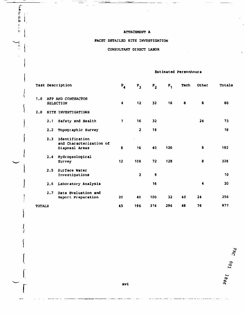
ATTACHMENT A
FACET DETAILED SITE INVESTIGATION
CONSULTANT DIRECT LABOR
Task Description
Estimated Personhours
P P P P Tech Other Totals
1.0 RFP AND CONTRACTORSELECTION
2.0 SITE INVESTIGATIONS
2.1 Safety and Health
2.2 Topographic Survey
2.3 Identificationand Characterization ofDisposal Areas
2.4 HydrogeologicalSurvey
2.5 Surface WaterInvestigations
2.6 Laboratory Analysis
2.7 Data Evaluation andReport Preparation
TOTALS
12 32 16 8 80
1
8
12
20
45
16
2
16
108
2
40
196
32 24
16
40 120 8
72 128 8
8
16 4
100 32 40 24
316 296 48 76
73
18
192
328
10
20
256
977
xvi03

;l
U
ATTACHMENT A (continued)
FACET DETAILED SITE INVESTIGATION
CONSULTANT DIRECT LABOR COSTS
Task Description
Rates ($ per hour)
1.0 RFP AND CONTRACTORSELECTION
2.0 SITE INVESTIGATIONS
2.1 Safety and Health
2.2 Topographic Survey
2.3 Identification andCharacterization ofDisposal Areas
2.4 HydrogeologicalSurvey
2.5 Surface HaterInvestigations
2.6 Laboratory Analysis
2.7 Data Evaluation andReport Preparation
Totals
Range
23
Estimated Cost ($)
P P2 P1 Tech Other Total
18 15 13 10
92 216 480 208 80 56 1132
23 288 480 168 959
36 240 276
184 288 600 1560 56 2688
276 1944 1080 1664 56 5020
36 120 156
240 28 268
460 720 1500 416 400 168 3664
1035 3528 4740 3848 480 532 14,163
$14,000 - $18,000
xvii
oo
00

ATTACHMENT B
FACET DETAILED SITE INVESTIGATION
OTHER DIRECT COSTS
TASK Cost Range ($)
1.0 RFP t Contractor Selection $350 - $550
2.1 Safety and Health10 Baseline Medical Profiles I $150 $1,5005 Medical Examinations 9 $350 1,750Sample Collection and Surveys
45 days x 8 hours/day 9 $15/hr40 hours - P e $23/hrDirect Labor (DL)
- Total Labor Cost - D.L. x 2.2Contingency • 20%Subtotal $16,685
Total Cost - Safety and Health $19,935Range - Safety and Health $18,000 - $22,000
2.2 Topographic Survey (Based on Information $3,000 - $5,000from Photoscience, Inc.)
2.3 Identification and Characterization of Disposal Areas- 5 sites x 4 holes per site x 30 ft
depth per hole with sampling -600 ft § $6.50/ft $3,900
- 5 sites x 12 holes per site x 10 ftdepth per hole with sampling »600 ft @ $6.50/ft 3,900
- 5 sites x 4 GW samples per site •20 GH samples 9 $10 200
- 5 sites x 4 holes per site x 2 splitspoon samples per hole - 40 samples9 $12 480
- Surveying, Layout, and Levelling3 persons x 3 days
- Investigation of tunnel on site- Mobilization- Report - 40 hrs 9 $23/hr x 2.2- Subtotal- Contingencies 20%
- Total Cost - Identification andCharacterization of Disposal Areas $19,917
- Range - Identification and Charac-terization of Disposal Areas $19,000 - $22,000
xviii
00itk00

• IATTACHMENT B (Continued)
FACET DETAILED SITE INVESTIGATION
OTHER DIRECT COSTS
TASK Cost Range ($)
2.4 Hydrogeologic Survey and Groundwater ModellingHydrogeologic Survey
Mobilization $ 900Construct 10 wells § $25/ft. 20,000Develop 10 wells § $100 each 1,000Insitu Permeability Testing
5 wells: 8 hrs 9 $90/hr 720Surveying, Layout, and Levelling
3 persons x 3 days10 wells x 1 GW Sample § $10Report - 40 hrs « $23/hr x 2.2Subtotal
j - Contingencies 20% __' - - Total Cost - Hydrogeologic Survey $32,285
- Groundwater ModellingData Collection and Review
P - 24 hours i $23/hr 552Tech - 40 hours § $15/hr 600
Running Model (3 runs 8 2 days each)P - 48 hrs e $23/hr 1,104Total DL $ 2,256
Total Labor Cost « 2.2 x DL 4,963Computer Time 100Miscellaneous ODCs 150Subtotal $ 5,213
Contingencies - 20% 1,043Total Cost - Groundwater Modelling $ 6,256
Total Cost - Hydrogeologic Survey $38,541and Groundwater Modelling
Range - Hydrogeologic Survey andGroundwater Modelling $37,000 - $43,000
2.5 Surface Water InvestigationCollect 10 surface water & 10 sediment
samples >P - 16 hrs 8 $23 $ 368 °Tech - 40 hrs « $15 600
- DL $ 968 5Total Labor Cost - DL x 2.2 2,130 M
Miscellaneous - Transport, ODCs 170Subtotal $ 2,300 £Contingencies - 20% 460 *Total Cost - Surface Hater
Investigation $ 2,760Range - Surface Water Investigation $2,000 - $4,0v«
xix
r
II.I
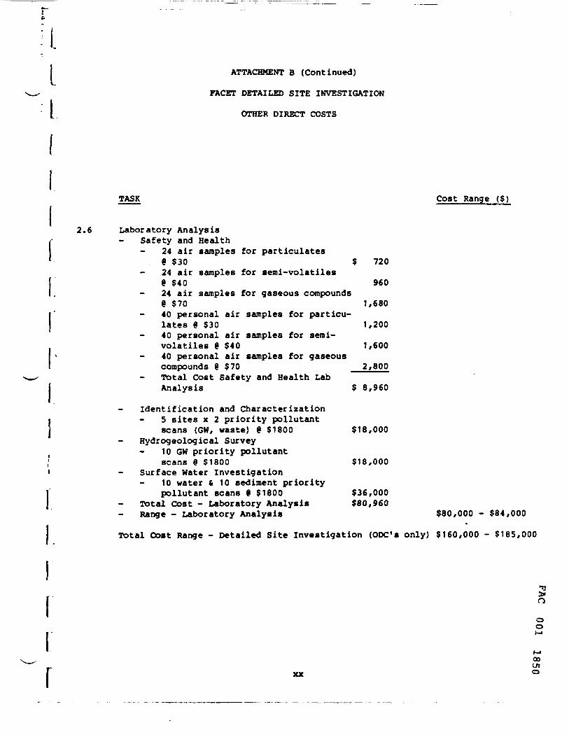
ATTACHMENT B (Continued)
FACET DETAILED SITE INVESTIGATION
OTHER DIRECT COSTS
TASK Cost Range ($)
2.6 Laboratory AnalysisSafety and Health
24 air samples for particulates§ $30 $ 72024 air samples for semi-volatiles9 $40 96024 air samples for gaseous compounds« $70 1,68040 personal air samples for particu-lates % $30 1,20040 personal air samples for serai-volatiles 9 $40 1,60040 personal air samples for gaseouscompounds § $70 2,800Total Cost Safety and Health LabAnalysis $ 8,960
Identification and Characterization5 sites x 2 priority pollutantscans (GW, waste) i $1800 $18,000
Hydrogeological Survey10 GW priority pollutant
I scans £ $1800 $18,000> - Surface Water Investigation
r
- 10 water (10 sediment prioritypollutant scans 9 $1800 $36,000
Total Cost - Laboratory Analysis $80,960Range - Laboratory Analysis $80,000 - $84,000
Total Cost Range - Detailed Site Investigation (ODC's only) $160,000 - $185,000
xx
3noo
00<J1o

0 4 8 12
WEEKS
16 20 24 28 32 36
1.0 RFP & CONTRACTOR SELECTIONB.O SITE INVESTIGATIONS
2.1 Safety and Health
2.2 Topographic Survey2.3 Identification and Characterization
of Disposal Areas2.4 Hydrogeological Survey2.5 Surface Water Investigations2.6 Laboratory Analysis2.7 Data Evaluation and Report Prepara-
tion3.0 FEASIBILITY STUDY - REMEDIAL ACTIVITIES
3.1 Source Control Actions3.2 Off-site Control Actions
4.0 DESIGN/CONTRACT DOCUMENTS
5.0 IMPLEMENTATION6.0 COMMUNITY RELATIONS
IIIHIIIIIIII
iiiiiiiiiiiiiii inmiiiimi'IIIIIIIIHI
Illlllllllllll IIIIIIIIIIIIIII
iiimniimiiiiiiniiiiii
iiiiiniiiiiiiii iiiiiiiiiiiiiin iiliilililiiini
FIGURE 3-5 FACET ENTERPRISES
REMEDIAL ACTION SCHEDULE
Continuous Effort
Intermittent Effort
Undefined start and duration
IS8I TOO DVJ

I
I
r
1.0 DATA COMPILATION AND EVALUATION fc. l ^ ^ t
1.1 Objective ^ • ^ i'
The objective of this section is the compilation and evaluationof the available data on the Facet Enterprises uncontrolled hazardous wastedisposal site. Compilation of available data is a necessary step in thedevelopment of an approach to site remedial actions. The available dataserve as a baseline of information which is used in assessing the sitesituation. This evaluation of existing data provides a mechanism fordetermining data limitations. The data are also useful in identifying andevaluating appropriate remedial measures and techniques.
1.2 Background
1.2.1 Site Location
Facet Enterprises is located 3/4 of a mile north of the cityof Elmira in Chemung County, New York (Figures 1-1 and 1-2). The plantis situated in a commercial-residential section of Elmira Heights at18th Street just west of Route 14. The approximate latitude and longitudeat the site are 42°08'00" and 76°50'00" respectively. The plant isbordered by residential-industrial areas except to the north where there isa community golf course. Three population centers, Elmira, Elmira Heights,and Horseheads are located within a 5 mile radius of the plant site. Amore detailed site map of Facet Enterprises is presented in Figure 1-3.
1.2.2 Site History
Facet Enterprises Motor Components Division is an active motorparts manufacturing firm occupying a 31 acre site. On-site disposalof metal wastes-liquids and sludges, oil wastes, solvent wastes and othermaterials occured from at least the 1940's to late 1978 or early 1979.NYSDEC documents indicate that the majority of the disposal was done bythe former plant owner, the Bendix Corporation. Facet Enterprises took
ooinNJ

.I
PAC001
1853

r,L FIGURE 1-2 LOCATION OF FACET ENTERPRISES INC.
•x t
'•• - \ ^
- >"
i • ,--.-v-p;^^^^^;--5'^I . '>:^%-t>-^:-<^=---:>.-:-l.• I . ' ] > ' / • • - " • . •'-'- <^< : s AI c -' -^ / -' ^^-^-^ X x'\--''^ ' - • . • ' '-^n ; v;^ i • • ->•; . •- / •/-x / / - i/.•«: mi\j^eau
A' < • •' :' •"'A - 1 ; \ ,-i > -*; ".-A- /. ^ * .'^- -i-•'%\"::JJ> f- -^'"\:
^V'^3 ' '"-;-- - '
Go:
•-•. ^. ,->'--"•- — "*" ^-. i r ..r •v ~'
i^* ^—*- .*' 3 • i— '• j - • .
^-'/.
\" ';. ',\ G! i- T
, .-4 •^^.,,-1*r'~
' .ROUTE 14 -^
_s.i ^
:D" 1-:.
—• ;i
r
I'
X .
\
•• "r *? . - - •> •"><:•

OPEN DITCH
NORTH
LEGEND
1-Burial Area tl2-Burial Area 123-Burial Area 134-Covered Oil Lagoon5-OId Sand Filter
DIRECTION OF DRAINAGE WATER FLOW
FIGURE 1-3 FACET ENTERPRISES - WASTE DISPOSAL SITE LOCATIONS
SS81 100

L over the plant in 1976, and discontinued all on-site disposal except thatof netal hydroxide sludge from their industrial wastewater treatment plantto a sludge drying bed (formerly used as a sand filter). This practice wasdiscontinued in 1979. Extensive grading was done by Facet in 1979 as wellas the construction of ditches to divert surface water around the wastedisposal areas. Facilities were also constructed for the collection andtreatment of leachate from the disposal areas.
The site consists of a relatively flat area containing thefacility's 30 buildings and an area with slopes of 5 to 10% rising to thewest in which the disposal areas are located. These disposal areasinclude three solid and liquid waste burial areas, one covered oil treat-ment lagoon, and one sand filter which was also used as a sand dryingbed. All of these facilities are presently inactive. There is also apond area which collects leachate from the solid and liquid disposalsites. This leachate is stabilized with lime and pumped into the plant'swastewater treatment system. Hastes known to have been disposed on theFacet property include: cyanide salt heat treating waste, heavy metalsludge from a wastewater treatment plant, zinc, nickel, cadmium, chromium,polymer coagulating agents, chlorides, sulfides, solvents and variousquenching and cutting oils (NYSOEC, 1979; EPA, 1982b).
Descriptions of the disposal areas shown on Figure 1-3 follow:Burial Area 11. - This pit, about 50 ft. x 50 ft. x 15 ft. deep
was used from 1960 to 1971 for the disposal of plating waste, oil sludgeand grinding waste. Drums of liquid were emptied into the pit and allowedto seep away and, on occasion, damaged drums were deposited as well.Periodic attempts were made to neutralize the disposed acidic wastes.Lime and caustic solutions were added to the pit when it was permanentlycovered (NYSDEC, 1979).
Burial Area 12. - This hillside area, about 40 ft. wide, 40 to50 ft. long and 10 to 15 ft. deep was used from the early 1960's to 1971.Wastes were dumped over a bank and allowed to soak into the ground.
1 Plating wastes apparently were disposed at the site only during winterI
•months when access to Burial Area fl was difficult. Attempts were made to\ neutralize the area before covering it with soil each spring. Lime andt1 caustic solutions were added to the pit when it was permanently covered
(NYSDEC, 1979). t-»CO

a." L
Ii:
Burial Area 13. - This steep bank, 30 ft. to 40 ft. wide, wasused for disposal of plating wastes and oil sludges from early 1940 toearly or mid-1960. Until recently it was used for disposal of old con-tainers, wood, metal, cinder blocks, and general solid waste along withsome chemicals. The bank was filled outward about 40 ft. to 50 ft. and is15 ft. high. This area was permanently covered and no longer receives waste(NYSDEC, 1979; EPA, 1982b).
Covered Oil Lagoon - This lagoon, about 200 ft. x 60 ft., locatedon the southern side of the plant site, was active from at least 1943 tothe early 1970's when its use was discontinued and it was covered. Duringits active period, it was used to remove insoluable oil from the plant'sdischarge (Herrington, 1981a; EPA, 1982b).
Old Sand Filter - This area, on the northern portion of theplant site, has been in existence since at least 1943. At one time, it wasused as a sand filter to treat the plant's sanitary wastewater. It wasbeing used for the disposal of metal hydroxide sludge from the plant'sindustrial wastewater treatment plant when its use was discontinued in1979. It has since been covered. (Herrington, 1981a; EPA, 1982b).
An underground tunnel at the site, which was constructed in1941 and probably used as an underground firing range, should also beinvestigated for the presence of hazardous materials. The tunnel, believedto have been constructed by Bendix, was probably not used after the mid-1950's. The circular structure, whose present condition is described asexcellent, is 3 1/2 to 4 feet in diameter and is said to extend from 60 to100 yards into the hillside just west of the plant building. A small roommay be located at the far end of the tunnel (by telephone, Mr. ReaveHowland, Facet Enterprises, February 4, 1983).
The plant currently holds two permits issued by the New YorkState Department of Environmental Conservation (NYSOEC). Hastewaterdischarges are regulated by State Pollution Discharge Elimination System(SPDES) permit INY004081 and air pollutant discharges by air permit1073001-0079. The plant currently generates 1200 gallons of metal sludge ^and 100 gallons of waste oil annually. These materials are removed and odisposed off-site by a contractor (Leichter, 1980). o
o
COen

IIr
The following is a brief chronological list of events relatedto disposal practices and contamination problems at the site:
1940 - Haste disposal was initiated at burial area 13(NYSDEC, 1979).
1943 - Approximate time that oil lagoon was constructed andits use as a treatment facility was initiated(Herrington, 1981a; EPA, 1982b).
1960 - Disposal of process waste at burial area 13 was discon-tinued and disposal at burial area 11 and burial area 12was started (NYSDEC, 1979).
1971 - Use of burial area 11, burial area 12 and the wasteoil lagoon was discontinued (NYSDEC, 1979;Herrington, 1981a).
1976 - Facet Company replaced Bendix Corporation as facilityowner (EPA, 1982b).
1979 - On-site disposal of process wastes was discontinued(Herrington, 1981 a).
1979 - NYSDEC required Facet to undertake extensive site gradingand drainage work to reduce leachate generation. Aconsent decree was issued (Leichter, 1980).
February 1980 - Work on leachate reduction system requiredby NYSDEC was completed (Leichter, 1980).
June 1980 - Site inspection and sampling investigation was donefor EPA by Fred C. Hart Associates, Inc. (Leichter, 1980).
September 1980 - Discovery of trichloroethylene contaminationprompts closing of Kentucky Avenue public water supplywells (Finster, 1980).
March 1981 - Initial site inspection and sampling investigationwas conducted by NYSDEC (Herrington, 1981a).
June 1981 - Second site inspection and sampling investigationwas conducted by NYSDEC (Herrington, 1981a).
March 1982 - Proposal for a hydrogeologic study of the site was TI!>submitted to Facet by Radian Corporation (Radian Corp., 1982). °
oo
00(Jl00
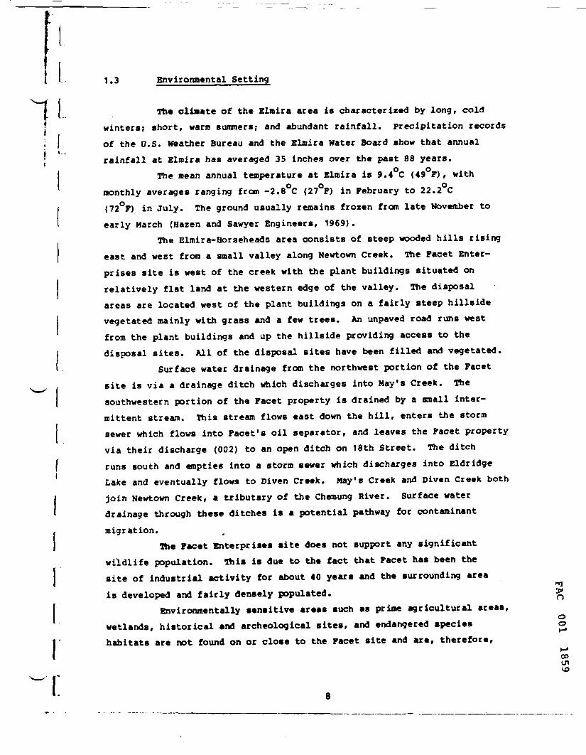
1.3 Environmental Setting
The climate of the Elmira area is characterized by long, cold( winters; short, warm summers; and abundant rainfall. Precipitation records; I of the D.S. Weather Bureau and the Elmira Water Board show that annuali *~~' rainfall at Elmira has averaged 35 inches over the past 88 years.
The mean annual temperature at Elmira is 9.4 C (49 F), withmonthly averages ranging from -2.8°C (27°F) in February to 22.2 C(72°F) in July. The ground usually remains frozen from late November toearly March (Hazen and Sawyer Engineers, 1969).
The Elmira-Horseheads area consists of steep wooded hills risingeast and west from a small valley along Newtown Creek. The Facet Enter-prises site is west of the creek with the plant buildings situated onrelatively flat land at the western edge of the valley. The disposalareas are located west of the plant buildings on a fairly steep hillsidevegetated mainly with grass and a few trees. An unpaved road runs westfrom the plant buildings and up the hillside providing access to thedisposal sites. All of the disposal sites have been filled and vegetated.
Surface water drainage from the northwest portion of the Facetsite is via a drainage ditch which discharges into May's Creek. Thesouthwestern portion of the Facet property is drained by a small inter-mittent stream. This stream flows east down the hill, enters the stormsewer which flows into Facet's oil separator, and leaves the Facet propertyvia their discharge (002) to an open ditch on 18th Street. The ditchruns south and empties into a storm sewer which discharges into EldridgeLake and eventually flows to Diven Creek. May's Creek and Diven Creek bothjoin Newtown Creek, a tributary of the Chemung River. Surface waterdrainage through these ditches is a potential pathway for contaminantmigration.
The Facet Enterprises site does not support any significantwildlife population. This is due to the fact that Facet has been thesite of industrial activity for about 40 years and the surrounding areais developed and fairly densely populated. %
Environmentally sensitive areas such as prime agricultural areas,wetlands, historical and archeological sites, and endangered species ohabitats are not found on or close to the Facet site and are, therefore,
ooUlVO
irr
not a consideration. The floodplain of a tributary to Newtown Creek islocated adjacent to the plant site on the east side of Route 14, but isnot affected by activities on the site itself.
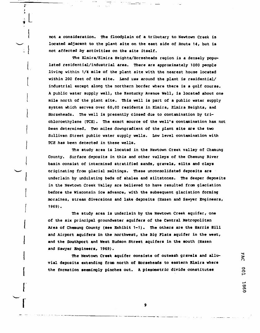
The Elmira/Elmira Heights/Rorseheads region is a densely popu-lated residential/industrial area. There are approximately 1000 peopleliving within 1/4 mile of the plant site with the nearest house locatedwithin 200 feet of the site. Land use around the plant is residential/industrial except along the northern border where there is a golf course.A public water supply well, the Kentucky Avenue Hell, is located about onemile north of the plant site. This well is part of a public water supplysystem which serves over 60,00 residents in Elmira, Elmira Heights, andHorseheads. The well is presently closed due to contamination by tri-chloroethylene (TCE). The exact source of the well's contamination has notbeen determined. Two miles downgradient of the plant site are the twoSullivan Street public water supply wells. Low level contamination withTCE has been detected in these wells.
The study area is located in the Newtown Creek valley of ChemungCounty. Surface deposits in this and other valleys of the Chemung Riverbasin consist of intermixed stratified sands, gravels, silts and claysoriginating from glacial meltings. These unconsolidated deposits areunderlain by undulating beds of shales and siltstones. The deeper depositsin the Newtown Creek Valley are believed to have resulted from glaciationbefore the Wisconsin ice advance, with the subsequent glaciation formingmoraines, stream diversions and lake deposits (Bazen and Sawyer Engineers,
[ 1969).The study area is underlain by the Newtown Creek aquifer, one
of the six principal groundwater aquifers of the Central MetropolitanArea of Chemung County (see Exhibit 1-1). The others are the Harris Hilland Airport aquifers in the northwest, the Big Flats aquifer in the west,and the Southport and West Hudson Street aquifers in the south (Hazenand Sawyer Engineers, 1969).
The Newtown Creek aquifer consists of outwash gravels and allu-vial deposits extending from north of Horseheads to eastern Elmira wherethe formation seemingly pinches out. A piezonetric divide constitutes
oo<no

LL the northern boundary of the aquifer. The Newtown Creek aquifer is the
most fully evaluated of the County's principal aquifers. Hater levelobservations dating back to 1956 in some cases have been made at the Roy'sDairy, Sullivan Street, Kentucky Avenue and Hestinghouse wells. The BlmiraHater Board has been undertaking a program of test holes, permanent wellsand numerous pumping tests since 1957 (Hazen and Sawyer Engineers, 1969).
The U.S. Geological Survey (USGS) has prepared a summary open-file report on the geohydrology of the valley-fill aquifers of ChemungCounty (Miller et al, 1982). The following are extracts from the report onvarious aspects of the Newtown Creek aquifer in the vicinity of the studyarea. The surficial geology of the aquifer is presented in Exhibit 1-2.Outwash sands and gravels are seen to be predominant. A narrow band ofalluvial silt is located along the Newtown Creek in the eastern section ofthe aquifer. The Facet waste disposal site is seen to be located on Kameand Kame terrace sand and gravel of high permeability on the western fringeof the aquifer.
Cross-sections of the aquifer along alignments to the northt t
and south of the Facet site, Sections C-C and D-D , respectively,are presented in Exhibit 1-3. In Section C-C , the aquifer is seento be totally unconfined, of thickness up to about 40 feet, and overlyingvery shallow bedrock in the west, and deep lake silt and clay and lodgement
itill deposits of low permeability. At Section D-D , west of well 42-12,there are an upper unconfined and a lower aquifer that seems somewhatconfined by low to moderately permeable lake silt and fine sand deposits.East of well 42-12, the aquifer is thickest (up to about 150 feet thick)and seemingly confined to some extent by low permeability alluvial silt.Infiltration rates are moderate (0.63 to 2 inches per hour) throughoutmost of the aquifer including the Facet waste disposal site except inthe alluvial silt deposits along the Newtown Creek where very low rates ofless than 0.2 inches per hour are found (Miller et al, 1982).
A map of aquifer thickness is presented in Exhibit 1-4. Itshows the aquifer to be generally 20 to 40 feet thick but less than 20feet in the Facet area and from 40 to more than 100 feet thick in thesoutheast (Miller et al, 1982).
oo
r oo
10 S
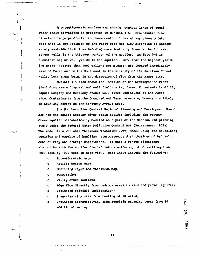
A potentionetric surface map showing contour lines of equalwater table elevations is presented in Exhibit 1-5. Groundwater flowdirection is perpendicular to these contour lines at any given point.Note that in the vicinity of the Facet site the flow direction is approxi-mately east-southeast then becoming more southerly towards the SullivanStreet wells in the thickest portion of the aquifer. Exhibit 1-6 isa contour map of well yields in the aquifer. Note that the highest yield-ing areas (greater than 1000 gallons per minute) are located immediatelyeast of Facet and to the Southeast in the vicinity of the Sullivan StreetWells, both areas being in the direction of flow from the Facet site.
Exhibit 1-5 also shows the location of the Westinghouse Plant(including waste disposal and well field) site, former Horseheads landfill,Kopper Company and Kentucky Avenue well sites upgradient of the Facetsite. Contaminants from the downgradient Facet area are, however, unlikelyto have any effect on the Kentucky Avenue Well.
The Southern Tier Central Regional Planning and Development Boardhas had the entire Chemung River Basin aquifer including the NewtownCreek aquifer mathematically modeled as a part of the Section 208 planningstudy under the Federal Water Pollution Control Act (Reisenauer, 1977a).The model is a Variable Thickness Transient (VTT) Model using the Boussinesqequation and capable of handling heterogenenous distributions of hydraulicconductivity and storage coefficient. It uses a finite differencealogorithm with the aquifer divided into a uniform grid of small squares1000 feet by 1000 feet in plan view. Data input include the following:
o Potentiometric map;o Aquifer bottom map;o Confining layer and thickness map;o Topography;o Valley cross sections;o Edge flow directly from bedrock areas to sand and gravel aquifer;o Estimated rainfall infiltration;o Transmissivity data from testing of 18 wells;
'flo Estimated transmissivity from specific capacity tests from 80 padditional wells;
oo
00
to
11

Jt
r
o A measured set of groundwater elevations from 90 wells (fallmeasurements); and
o Stress (groundwater withdrawals)Calibration of the model was only possible under steady state conditionsdue to limitations of the available data. The computer program permitssimulation of aquifer systems which are confined in some areas and uncon-fined in others (Reisenauer, 1977a).
The Chemung River Basin Groundwater Model permits the investi-gator to subdivide, extract and expand a part of the overall model thusallowing the study of local detail on a finer grid than is possible inthe regional model. The model has been tested on two regional and fivesubregional cases (Reisenauer, 1977b). Among the latter five cases testedwere a "Lagoon in Northwest Elmira Heights," and a "Sanitary LandfillEast of Roberts Hollow" between Elmira and the Chemung River. The loca-tion of the "Lagoon in Northwest Elmira Heights" relative to the FacetEnterprises wells indicates that it is probably one of the Facet lagoons.The area was expanded by a factor of three from the regional model. Thenorth and south boundaries were arbitrarily chosen and held constantat values designated by the regional model. The east boundary was NewtownCreek and the west boundary Harris Hill. Nine pumping wells in the areaare shown listed in Table 1-1 and on the computer map. Figure 1-4, gene-rated by the model. The map also shows estimated groundwater contoursand flow streamlines from the lagoon. Note that the streamlines travelin a generally southeasterly direction terminating at two sets of wells,the northern one owned by Thatcher Glass and the southern by GeneralElectric. The model generated streamline travel times are shown inTable 1-2. The travel times range from 14 to 20 years and representthe model estimated tines for contaminated groundwater from the lagoonto flow to the wells concerned (Reisenauer, 1977b).
It also seems possible for flow from the lagoon to reach thetwo Elmira Water Board wells in the extreme southeast of the map. Theseare the Sullivan Street Wells. Travel times would be longer. Perhaps ^also, depending on the pumping regime at the Facet Enterprises wells, it °is possible that flow from the lagoon may reach those wells. Note that oo»-•
»-i00
OJ
12
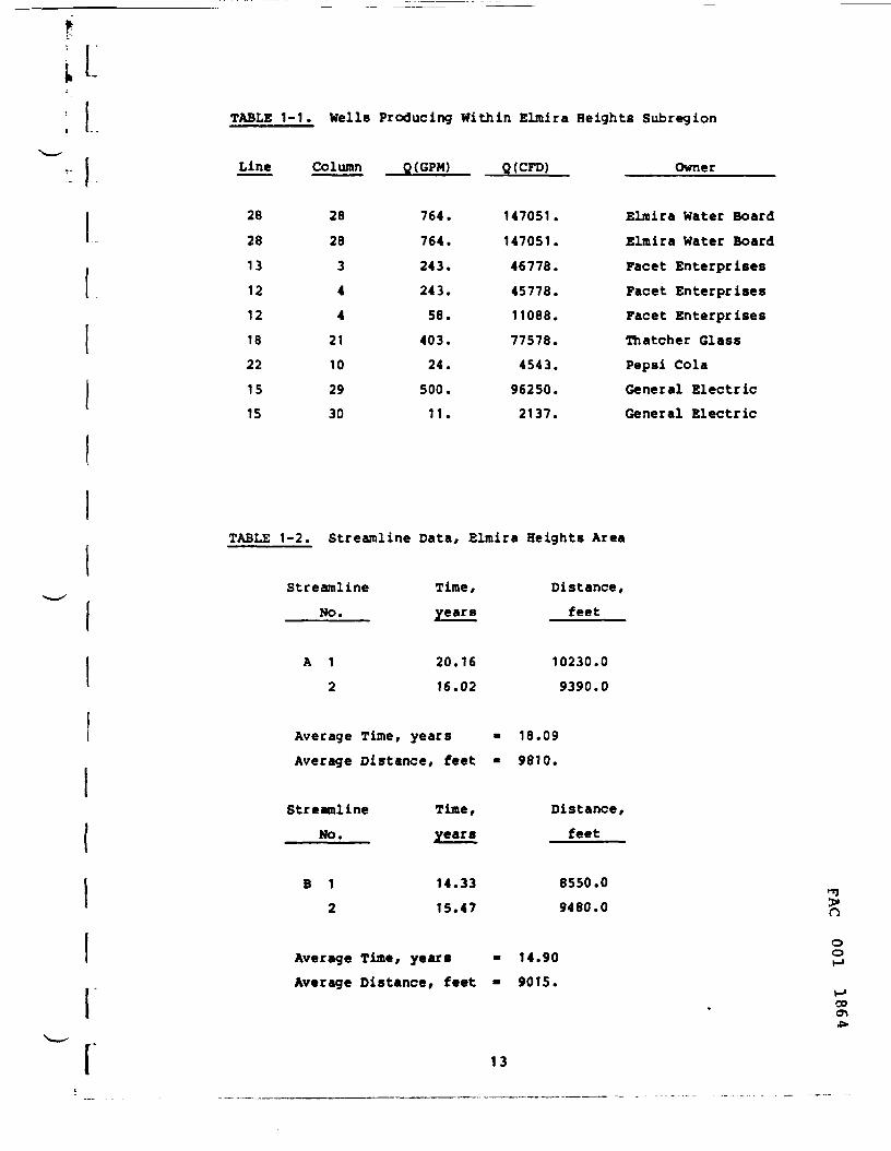
;L TABLE 1-1. Wells Producing Within Elmira Heights Subregion
Line Column Q(GPM) Q(CFD) Owner
28
28
13
121218221515
28
28
344
21
102930
764.
764.
243.
243.
58.
403.
24.
500.
11.
147051.
147051.
46778.
45778.
11088.
77578.
4543.
96250.
2137.
Elmira Water Board
Elmira Water BoardFacet EnterprisesFacet EnterprisesFacet EnterprisesThatcher GlassPepsi ColaGeneral ElectricGeneral Electric
TABLE 1-2. Streamline Data, Elmira Heights Area
r
Streamline Time,NO.
A 1
2
AverageAverage
years
20.1616.02
Time, years -Distance, feet -
Streamline Time,No.
B 1
2
AverageAverage
years
14.3315.47
Tine, years -Distance, feet -
Distance,feet
10230.09390.0
18.09
9810.
Distance,feet
8550.09480.0
14.909015.
"3>noo
00a\
13

<I
00dcX
2
Z31^
0O
1
.
«
»
:t
.Z
;3
,t:l2T
S23•i
r:
J7
«
:j3T
1.V.•1
11
• • -^J>JiL-_l>JrJ:• • • -\
/ ^*/^
\- \ -•'• • -4--t B;'- - - Z^O^, >\v: : : K' ^v^• • :> /\' 'S •' \: :\ / \
i -"-\V'•'•'•{ f \i /. . .' ' * C\N 1•'.'•m^. . . io'c1;/r-.o!.!l!. . . .cc. co j j i :
' ' ' ;\|: : : : : :1. . . . . . i. . . . . .^
; yx; \\ v^
'•'i.x r*i >; i-'i * i> i> 1^
* i > i N i ^ i > i " i s ' ^ j ' ' x ; " • • • * * • • •_- , -x j . . . . . . . . .
<f-r\^8 ^ - • - - • • • - •2 + --^^-i; - - - - • • • • •
^-856 - . . . . . . . . .
. . . . . . . . . !x, . . a. . . . . . .
o54^~^ ^-r- j-_^-— ^ "" --' • vx i . . ...
v X $ - . . . . . .\ 852/ $r. . . . . . .^V ^^ >v\\ .x^ !^-" * " " "
\' ^s* > 1
"\^ 4. fv" . . .\ / T »:—' \< \ iill • ' 'y"'%--J ^ •
/ ^.N ^/ ) V ITTf /y i/r"S/ 2±v v v^) ^
V 11' 1x|.''I/: 1 v- N !>••'] VI> l*'lxlxi'' |xlx7[>isTx!
I I 1 4 I * H it a ., n i* n tt .* s 3i s a s, f, a z>LINE N'JMBLRS'
FIGURE 1-4. Elmira Heights Subregion Showing Water TableContours and Streamlines from Lagoon
Oo
00
14
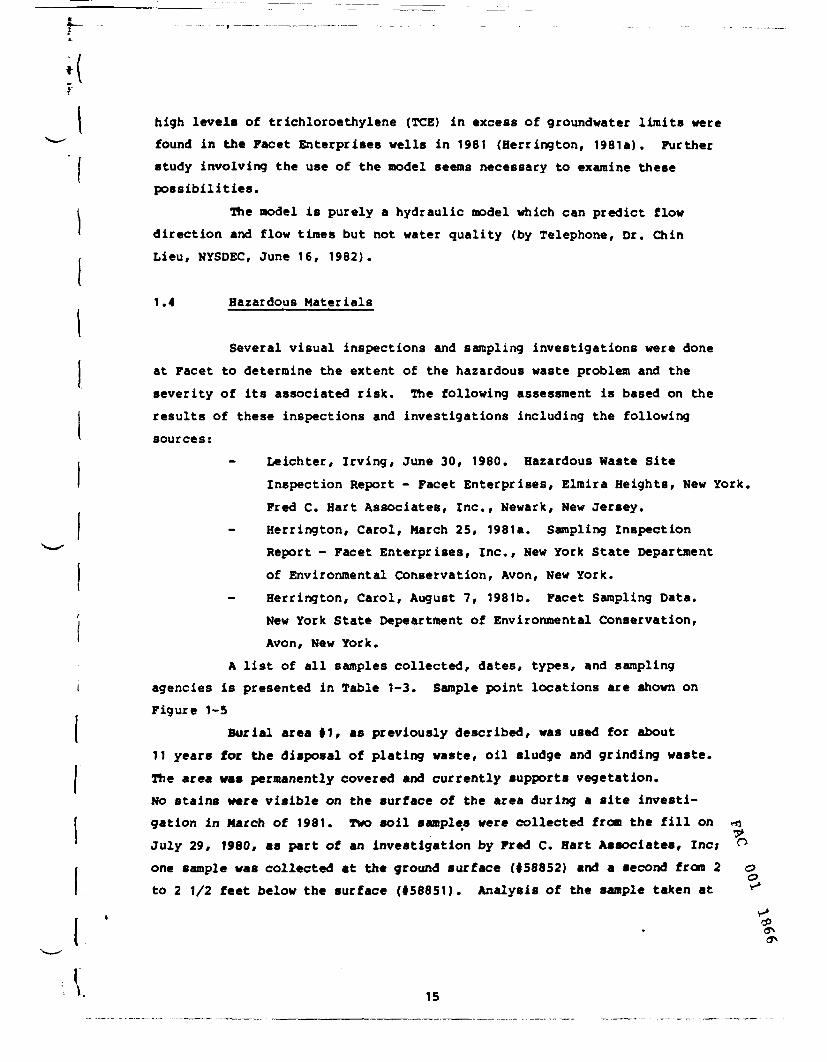
high levels of trichloroethylene (TCE) in excess of groundwater limits werefound in the Facet Enterprises wells in 1981 (Herrington, 1981a). Furtherstudy involving the use of the model seems necessary to examine thesepossibilities.
The model is purely a hydraulic model which can predict flowdirection and flow times but not water quality (by Telephone, Dr. ChinLieu, NYSDEC, June 16, 1982).
1.4 Hazardous Materials
Several visual inspections and sampling investigations were doneat Facet to determine the extent of the hazardous waste problem and theseverity of its associated risk. The following assessment is based on theresults of these inspections and investigations including the followingsources:
Leichter, Irving, June 30, 1980. Hazardous Haste SiteInspection Report - Facet Enterprises, Elraira Heights, New York.Fred C. Hart Associates, Inc., Newark, New Jersey.
- Herrington, Carol, March 25, 1981 a. Sampling InspectionReport - Facet Enterprises, Inc., New York State Department
I of Environmental Conservation, Avon, New York.i
Herrington, Carol, August 7, 1981b. Facet Sampling Data.New York State Depeartment of Environmental Conservation,Avon, New York.
A list of all samples collected, dates, types, and samplingagencies is presented in Table 1-3. Sample point locations are shown onFigure 1-5
Burial area 11, as previously described, was used for about11 years foe the disposal of plating waste, oil sludge and grinding waste.The area was permanently covered and currently supports vegetation.No stains were visible on the surface of the area during a site investi-gation in March of 1981. Two soil samples were collected from the fill on «\July 29, 1980, as part of an investigation by Fred C. Hart Associates, Inc; °one sample was collected at the ground surface (158852) and a second from 2 o
C
to 2 1/2 feet below the surface (158851). Analysis of the sample taken at *
CP
\. 15

• ••pit Ltca*tloa on lilt(lap
1
t
1
<
~~S
t
(
~~ S
11
1-1*1-na-*•M
la.pl abaala-Mtlen
5IIS1
SIIH
11151
li*S4
SIISS/SUM
511 SI/Sllll
Mill/Sllll
•0 14»/H» IDI
•0 IS*/HI I0»
tacatOlapoaalAraa
racat is
fatal «io•l-ttl-OI
•l-lfl-01
• I-KI-H
I1-l«l-0»
la CaMpla CaH
•4 C. Nan At
fa/-plattt4
7-1I-IO
1- H-H
7-11-10
7-11-10
7-11-10
7-11-10
7-lt-M
7-11-10
7-1I-IO
J-1S-OI
1-15-01
3-25-1, ——
1-1I-II
(-10-11
(-10-11
•-10-lt
t-10-01
1 It am lit)*loeUto. In,
(•nrl«J">r
're.. '
n:«A
rc»A
FCNA
KM
rciu
rcM
rou
rou
J WTSMCWTSDIC
wrsoccHISDCe
nsoansiKCHTSOCC
mrioec
mrsnec
mote
r burt«l araie.
luitrlalt».-plM
Soil
toll
Soil
Sol)
toll
s>ei«*nt
S*dl*«nt
W.l.c
••tor
•oil
ttetoi
Mator
IUt«c
Ale
llvdt*
foil
loll _____
HM«r
11* buriAl ftrai
>i Hoi* apacaa 01 tha tabla Indlc.ta that analyala 1
D<«tlptlon of !•*»!•Location
•Ulltl •!«« |1 - tclo*
•jtr.c.
• utf«c<
tjrlal *t*« 11 - btlowcrouf* mutfcci
l.ri.l .rt> 11 - >t ,,ou«4
""«c« _________________
Cov>rȣ oil lAfoon
north <,.ln.,, tilth
South ii.ln.a. diui,
North dr>ln»g« oltch
South dr«ln»« ditch
•orUl it.. |i. burial *r»12 or fcjrlal aiaa 13
north dralnaaa ditch
Outfall 00]-oll trap
Abova covtred oil lafOdN
Old Sand Ml tarConpoilt* - burial ar«a 11and burial araa 11
Ce»arad oil latooo _______
AaHirl
to
00
10
100
110
<.ei
so<.004
(.004
<.004
<.0*4
l.»
M
CrIK«>
110
,,-
»0
S40
1100
iioe
• 40
<.01
410
.040
.onit
.000
1IMM
11
CoCPfl
140
5)0
510
»00
110
<.01
1000
.S40
.000
.014
<.OI
ijeeo
is
South dralnaaa ditch <.I1 «.«J .MJ
11, or burial araa 1).
01 tha paramtar la ouaatlo* »a« not parforM*.
r»(f^i
140
100
140
100
1100
110
,0,
110
<.01
.04
<.0)
<.C1
100
<1
<.Q4
Sa(PP»
10
1
100
100
ItO
110
•
<s<.004
<.004
<.004
<.0(
<.004
Inlf?=>
70
10
1>00
110
11000
SIO
•»7
M
1.1
.075
.054
.ots
1SOOO
.17
.1C
CdIF?=>
4
,
100
1100
.001
.01
.00}
HOMO
11
<.ll
HI
IPP>)
S4
too
100
<-01
<.0]
.01
010
11
<.OI
mIPI")
10
10
1«
100
1C
10
<.l<.l
<.l
<1I
'1
<.s
Kl1111
IP;*!
10000
<.i
«.s110000
<1
Ntt^ylanacMcMdaIff-
to
<5
<)
<5
<10
tio100
s
raIPP»)
„
14
S
44
<10
100 '
<100
<5
1.1.1-II IcMoro-
• Ih.r,. |ppb)
11
<5
<S
CIO
000
<100
0
tianl 1.1-£lcMo(0-
• tt.rlan* (PP>-
<S
<S
S
<10
<100
<100
<5
TABLE 1-3
SAMPLES COLLECTED
too
16
AT
FACET ENTERPRISES INC.

OPEN DITCH
NORTH
LEGEND
1-Burial Area II2-Burial Area 123-Burial Area 134-Covered Oil Lagoon5-North Drainage Ditch6-South Drainage Ditch7-Outfall 0028-Leachate Lagoon9-Facet Well - (well isoff-site)
10-Old Sand Filter11-South Drainage Ditch
(off-site)
DIRECTION OF DRAINAGE WATER FLOW
FIGURE 1-5 FACET ENTERPRISES - SAMPLE POINT LOCATIONS
8981 100

the surface revealed the following concentrations: arsenic, 440 parts permillion (ppm); chromium , 1400 ppm; copper, 530 ppm; lead, 120 ppm; sele-nium, 100 ppm; and zinc, 150 ppm. The sample from below the ground surfacehad high concentrations of chromium, copper and lead with values of 120ppm, 240 ppm, and 140 ppm respectively.
During a sampling effort conducted by the New York State Depart-ment of Environmental Conservation (NYSDEC) on March 25, 1981, a sample wascollected from each of the three waste burial areas. Two of the sampleswere lost and the remaining sample was not labeled. The area of originof the remaining sample being unknown, it was relabeled "Facet DisposalArea.* When analyzed, the sample was found to have high concentrations ofthe following metals: chromium, 490 ppm; copper, 1000 ppm; lead, 230 ppm;and nickel, 600 ppm.
A composite sample from burial areas 11 and 12 was collectedby NYSDEC on June 10, 1981. The portion of the sample from burial area |1was taken about 2 feet below the surface and the portion from area 12, atthe surface. This sample (181-161-03) was analyzed for a variety ofpriority pollutants and found to have high levels of methylene chloride(610 parts per billion (ppb)) and trichloroethylene (200 ppb). Arsenic,cadmium, chromium, copper, nickel and zinc were found in the sample atconcentrations ranging from 17 to 33 ppm.
Burial area 12 was used for disposal of plating wastes and oilsludge for about 25 years. This area has been permanently covered and issparsely vegetated. During a March, 1981 site visit by NYSDEC, an areawith no vegetation and dark, brown, oily looking stains was noted.
Surface (158854) and sub-surface (158853) soil samples werecollected from burial area 12 by Fred C. Hart Associates, Inc. on July 29,1980. The sub-surface sample had high concentrations of the followingmetals: arsenic, 250 ppm; chromium, 360 ppm; copper, 310 ppm; and lead,100 ppm. The ground surface soil sample was analyzed for metals with theseresults: chromium, 540 ppm; copper, 260 ppm; lead, 140 ppm; selenium, 100ppm; and zinc, 2900 ppm.
Two soil samples were collected at burial area 12 by NYSDEC >O
during later sampling efforts. A sample collected on March 25, 1981 wasoo
00o*vo
16
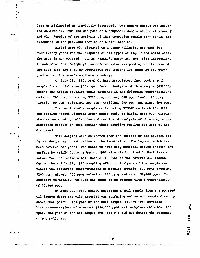
lost or mislabeled as previously described. The second sample was collec-ted on June 10, 1981 and was part of a composite sample of burial areas 11and 42. Results of the analysis of .this composite sample (81-161-03) arediscussed in the previous section on burial area 41.
Burial area 43, situated on a steep hillside, was used forover twenty years for the disposal of all types of liquid and solid wasteThe area is now covered. During NYSDEC's March 26, 1981 site inspection,it was noted that orange-yellow colored water was ponding at the base ofthe fill area and that no vegetation was present for about 20 ft. down-gradient of the area's southern boundary.
On July 29, 1980, Fred C. Hart Associates, Inc. took a soilsample from burial area 13'a open face. Analysis of this sample (45885S/58884) for metals revealed their presence in the following concentrations:cadmium, 200 ppm; chromium, 3200 ppm; copper, 580 ppm; lead, 100 ppm;nickel, 100 ppm; selenium, 200 ppm; thallium, 200 ppm; and zinc, 290 ppm.
The results of a sample collected by NYSDEC on March 25, 1981and labeled "Facet Disposal Area" could apply to burial area 43. Circum-stances surrounding collection and results of analysis of this sample aredescribed earlier in this section where sampling results for area 41 arediscussed.
Soil samples were collected from the surface of the covered oillagoon during an investigation at the Facet site. The lagoon, which hasbeen covered for years, was noted to have oily material oozing through thesurface by NYSDEC during a March, 1981 site visit. Fred C. Hart Assoc-iates, inc. collected a soil sample (458856) at the covered oil lagoonduring their July 29, 1980 sampling effort. Analysis of the sample re-vealed the following concentrations of metals: arsenic, 800 ppm; cadmium,1200 ppm; nickel, 100 ppm; selenium, 160 ppm; and zinc, 32,000 ppm. Inaddition to metals, PCB-1248 was found to be present with a concentrationof 10,000 ppb.
On June 20, 1981, NYSDEC collected a soil sample from the coveredoil lagoon where the oily material was surfacing and an air sample directlyabove that point. Analysis of the soil sample (481-161-04) revealedhigh concentrations of PCB-1248 (320,000 ppb) and methylene chloride (200 >ppb). Analysis of the air sample (481-161-01) did not detect the presence
oof any pollutant. o
M00
o19

A grab sample of metal hydroxide sludge (ft81-161-02) was takenfrom the pile on the old sand filter by NYSDEC on June 10, 1961. Analysisfor thirteen priority pollutant metals showed high concentrations ofcadmium (130,000 ppm), chromium (130,000 ppm), copper (13,000 ppm), lead(180 ppm), nickel (880 ppm), and zinc (35,000 ppm).
A water sample (FACET ft 9) was collected by NYSDEC on March 25,1981 from the leachate lagoon which collects leachate from burial areas 11and |2 and surface water drainage from the northwestern portion of theFacet property. The water in the lagoon was noted as having a bright greencolor on the day of sampling. Analytical results indicated 16 ppm chro-mium, 29 ppb 1,1,1 - trichloroethane, and 180 ppb trichloroethylene (TCE).
Facet's process water supply well located east of Route 14 wasused by NYSDEC to obtain a groundwater sample on March 25, 1982. Metalconcentrations in this sample (FACET 110) were low but two volatile com-pounds were detected. Trans-1,2-dichloroethylene was present at 5 ppb andTCE at 44 ppb.
Both surface water and bottom sediment samples were collectedfrom the drainage ditches which convey surface water drainage, leachate,and treated plant wastewater from the site. The northern drainage ditchdrains the northwest portions of the site. Sediment from the bottom of theditch was collected by Fred C. Hart Associates, Inc. on July 29, 1980.Analysis of the sample (158857/58881) revealed high levels of these me-tals: chromium, 940 ppm; copper, 680 ppm; lead, 160 ppm; selenium, 220ppm; and zinc, 580 ppro. A surface water sample (ftBO 149/MB 8038) was alsocollected during the same investigation. Analysis of this water sampleshowed relatively low concentrations of metals (less than .3 ppm for allmetals analyzed) but notable levels of TCE (31 ppb) and methylene chloride(13 ppb). NYSDEC collected another water sample from the north drainageditch (FACET 15) on March 25, 1981. No metals were present in the sampleat concentrations above 2 ppm, however, analysis did detect 21 ppb 1,1,1-trichloroethane and 34 ppb TCE.
The south drainage ditch drains the southwestern portion ofthe Facet site. Hater from this ditch flows into a storm sewer, throughan oil trap, and off the plant site through outfall 1002. A sediment oo
v-1CP
20

sample (58858/58882) from the bottom of the ditch was collected on July 29,1980 by Fred C. Hart Associates, Inc. Analysis of this sample revealedhigh levels of arsenic (80 ppm), cadmium (76 ppra), chromium (780 ppm),copper (540 ppm), lead (280 ppm), selenium (140 ppm), and zinc (380 ppm).A surface water sample (BO 150/MB 8039) was collected during the sameinvestigation. Results of metal analyses at the south ditch, like thenorth, showed less than .3 ppra for all metals analyzed. Methylene chlo-ride concentrations of 60 ppb were also found.
Additional surface water samples were taken from the southdrainage ditch by NYSDEC on March 25, 1981 and June 10, 1981. The earliersample (FACET 17) was taken from the final chamber of the oil separatoron the southern portion of Facet's property near outfall 1002. Results ofmetal analyses showed concentrations less than 2 rag/1 for all metalstested. TCE was present at a concentration of 5 ppb. The June 10, 1981water sample by NYSDEC (81-161-06) was collected just outside of the plantfence near 18th Street. Concentration of metals from this sample were verylow. Other compounds detected included 1,1,1-trichloroethane (8 ppb) andmethylene chloride (5 ppb).
Results of sampling efforts at Facet reveal that some of thecontaminants present in soil samples from Facet's waste disposal areasare also present in samples of leachate, drainage ditch sediments, andsurface and ground waters. Existing evidence indicates that contaminantsare leaving the Facet site by way of surface waters and drainage ditchsediments. Groundwater sample results indicate that contaminant movementthrough the groundwater is possible at Facet but not definitely attribu-table to Facet's activities since there are also several other potentialcontamination sources in the aquifer. Any of these potential sources couldbe affecting Facet's well. Further discussion concerning the migration ofcontaminants from Facet is provided in section 1.5.
1.5 Conceptual Site Model - Waste Migration
^Based on the results of sampling efforts at the site, two pos- >sible major pathways for off-site movement of contaminants have been
oidentified: surface waters (and associated sediments) and groundwater. o
CO
21

tI
High concentrations of trichloroethylene (TCE) were found ina composite soil sample from burial areas 1 and 2 and high methylenechloride concentrations were also found in soil samples from the coveredoil lagoon. Soil samples from each of the five disposal areas containedhigh concentrations of metals. Hater samples taken from the leachatelagoon contained notable concentrations of chromium, TCE, and 1,1,1-trich-loroethane, indicating that contaminants are leaching from the disposalareas.
A total of five surface water samples were collected from thenorth and south ditches draining the site. All of these samples containedhigh levels of one or more of the organic compounds listed above, confirm-ing suspicions that volatile organic compounds are leaving the site via thesurface waters. It is not known how persistent these compounds are indownstream waters, but there is a high probability that the natural turbu-lence and aeration associated with surface water flow will cause some ofthese volatile organic compounds to volatilize, reducing their negativeimpacts downstream.
One sediment sample was collected from Facet's north drainageditch and one from the south drainage ditch. Analysis of these samplesshowed the presence of high concentrations of a number of heavy metals.These results indicate that metals are escaping from the disposal areas,binding with soil particles, and migrating downstream in the bottom sedi-ments of drainage ditches. The movement of metals in this fashion isvery slow except during periods of heavy rainfall when the force of largequantities of water moving through the drainage ditches could move signi-ficant quantities of sediments. Unlike volatile organic compounds, heavynetals are very persistent.
It is possible that volatile compounds are escaping from Facetthrough the groundwater, although this cannot be confirmed by currentlyavailable information. A groundwater sample collected from Facet'sprocess water well located about 2500 feet east of the plant site revealedhigh levels of TCE, the source of which may or nay not be Facet. Thepresently available information is not sufficient to determine the sourceof the Facet well's contamination. Based on examination of presently oo
00-J
22

available data, some contaminants (possibly volatile organics) are probablyescaping from the Facet site via the groundwater. Volatile organic com-pounds would be likely to be more persistent in the groundwater than thesurface water. This is due to the slow flow of groundwater along with itslack of exposure to the air which combine to inhibit volatilization ofthese compounds.
1.6 Data Limitations
Site inspections and sampling investigations done at Facetprovide good general information on the location and content of wastedeposited on the site. Detailed information concerning the characteristicsand area! extent of wastes, the characteristics of the soil and ground-water, the extent of surface and groundwater contamination and the subsur-face geology at Facet is not available. This information is necessarybefore the extent of the surface and groundwater contamination problem canbe accurately evaluated. Completion of the detailed site investigationoutlined in Section 3 will satisfy these data requirements. This investi-gation will include the following studies and surveys:
o Safety and Bealth Plano Topographic Surveyo Identification and Characterization of Disposal Areaso Hydrogeological Surveyo Surface Water Investigationso Laboratory AnalysesThe information generated by these studies is necessary to
determine what types of waste materials are present, the areal extent ofdeposited wastes, and the extent to which contaminants are escaping fromthe site. The information is also necessary for a feasibility study ofremedial action alternatives.
1.7 Site Inspection
A preliminary site tour of the designated waste disposal areas >O
of Facet Enterprises Inc was made on May 11, 1982 by personnel from EPAoo
00•vl
23

Region II, Chemung County Health Department, Camp, Dresser and McKee, Inc.and C. C. Johnson and Associates, Inc. The purpose of this site visit wasto observe existing conditions including a first-hand look at the problemareas, and to meet with the current owner who is familiar with the historyof the site. No sampling was intended or undertaken during this sitevisit. The following section summarizes the observations resulting fromthe preliminary site tour.
The official of Facet Enterprises who guided the site inspectionon May 11, identified three wastes burial areas, one sand filter and onecovered oil lagoon at the site which lies on a hillside west of the plantbuildings of Facet Enterprises Inc. All disposal areas were found pre-sently inactive. Access to the site is limited by fencing. The site isadjacent to a predominantly residential area. The Mark Twain CommunityGolf Course adjoins the site on the north.
Facet Enterprises has installed a leachate collection pond atthe site. The leachate is pretreated in the pond, treated at the indus-trial wastewater treatment plant of the facility and discharged into theexisting sanitary sewer system. The leachate in the lagoon showed adistinct green color. The surface drainage from the site after oilseparation enters local creeks via existing storm sewers.
The waste burial area No. 1 as shown on Figure 1-3 is locatedon a hill on the northwest portion of the Facet property west of theaccess road. This area was found to be vegetated with grass and shrubs.There was no visible surface stain in this area.
Waste burial area No. 2 as shown on Figure 1-3 lies east of theaccess road. This area is gravelly and sparsely vegetated.
Waste burial area No. 3 as shown on Figure 1-3 is located onthe southwest portion of the Facet property. It is on a steep slopecovered with some grass and shrubs. Some wood and paper wastes werevisible near the base of the fill. It appeared that final cover, gradingand seeding of this area has not yet been completed. The steep surfaceslope at the face of this area will require considerable additional cover ^and grading to bring it to a well designed slope. n
ooM
M00
en
24
I
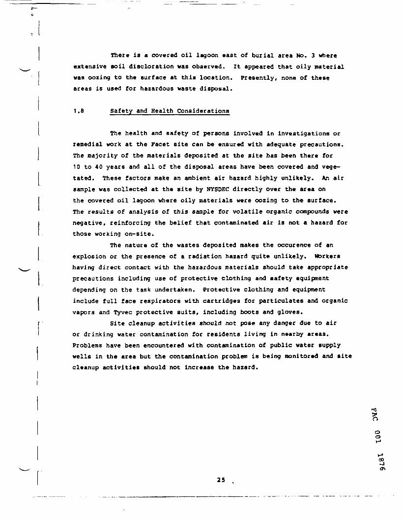
There is a covered oil lagoon east of burial area No. 3 whereextensive soil discloration was observed. It appeared that oily materialwas oozing to the surface at this location. Presently, none of theseareas is used for hazardous waste disposal.
1.8 Safety and Health Considerations
The health and safety of persons involved in investigations orremedial work at the Facet site can be ensured with adequate precautions.The majority of the materials deposited at the site has been there for10 to 40 years and all of the disposal areas have been covered and vege-tated. These factors make an ambient air hazard highly unlikely. An airsample was collected at the site by NYSDEC directly over the area onthe covered oil lagoon where oily materials were oozing to the surface.The results of analysis of this sample for volatile organic compounds werenegative, reinforcing the belief that contaminated air is not a hazard forthose working on-site.
The nature of the wastes deposited makes the occurence of anexplosion or the presence of a radiation hazard quite unlikely. Workershaving direct contact with the hazardous materials should take appropriateprecautions including use of protective clothing and safety equipmentdepending on the task undertaken. Protective clothing and equipmentinclude full face respirators with cartridges for particulates and organicvapors and Tyvec protective suits, including boots and gloves.
I Site cleanup activities should not pose any danger due to airI or drinking water contamination for residents living in nearby areas.
Problems have been encountered with contamination of public water supplywells in the area but the contamination problem is being monitored and sitecleanup activities should not increase the hazard.
oo
00JON
25

2.0 REMEDIAL PLANNING ACTIVITES
2.1 INITIAL REMEDIAL MEASURES
2.1.1 Objective
Initial remedial measures are straightforward, require a minimumof planning, can be implemented quickly and are consistent with the finalremedy. The measures are used to clean up or alleviate situations thatimpose significant safety or health problems.
2.1.2 Data Analysis
Several samples collected at Facet indicate the presence ofa trichloroethylene (TCE) contamination problem (see Section 1.4). Agroundwater sample collected by NYSDEC from Facet's process water well wasanalyzed and found to have a TCE concentration of 44 ppb. Such concentra-tions of an organic compound are cause for serious concern since Facet'swell taps an aquifer which supplies drinking water to a large number ofpeople. The actual location of Facet's well is east of Route 14 about2500 feet from the plant site. Thus, the high TCE concentration is anindicator of the presence of contaminants in the aquifer without indicatingits source. A hydrogeologic study of the Facet site will be required toassess Facet's role, if any, in the contamination of the aquifer.
Pollution of surface waters may also pose a threat to nearbyresidents, although possibly not as serious as that posed by groundwatercontamination. Two water samples were collected from the plant's northdrainage ditch. Results of analysis of these samples revealed TCE levelsof 31 ppb and 34 ppb. Three water samples were collected from the southdrainage ditch; one of the samples had 60 ppb methylene chloride whichwas the only pollutant detected with a concentration greater than 10 ppb.It is not known how persistent these compounds are and what their effectsare on the downstream water quality. Additional investigations of surface 5
owater quality, discussed in Section 3.6, will be required to determinethe full extent of the surface water contamination problem. §
oo-j
26
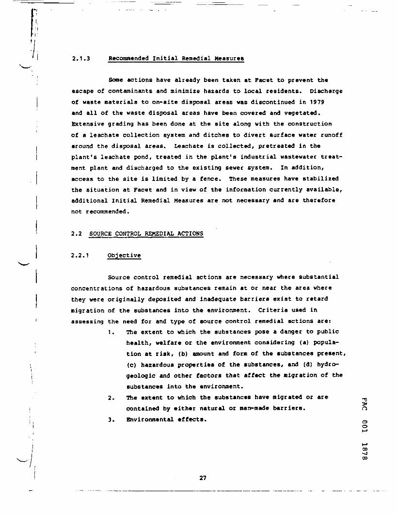
2.1.3 Recommended Initial Remedial Measures
Some actions have already been taken at Facet to prevent theescape of contaminants and minimize hazards to local residents. Dischargeof waste materials to on-site disposal areas was discontinued in 1979and all of the waste disposal areas have been covered and vegetated.Extensive grading has been done at the site along with the constructionof a leachate collection system and ditches to divert surface water runoffaround the disposal areas. Leachate is collected, pretreated in theplant's leachate pond, treated in the plant's industrial wastewater treat-ment plant and discharged to the existing sewer system. In addition,access to the site is limited by a fence. These measures have stabilizedthe situation at Facet and in view of the information currently available,additional Initial Remedial Measures are not necessary and are thereforenot recommended.
2.2 SOURCE CONTROL REMEDIAL ACTIONS
2.2.1 Objective
Source control remedial actions are necessary where substantialconcentrations of hazardous substances remain at or near the area wherethey were originally deposited and inadequate barriers exist to retardmigration of the substances into the environment. Criteria used inassessing the need for and type of source control remedial actions are:
1. The extent to which the substances pose a danger to publichealth, welfare or the environment considering (a) popula-tion at risk, (b) amount and form of the substances present,(c) hazardous properties of the substances, and (d) hydro-geologic and other factors that affect the migration of thesubstances into the environment.
2. The extent to which the substances have migrated or arecontained by either natural or man-made barriers.
3. Environmental effects. 0o
00J00
27

ri
V I
As stated in Section 1.6, the identification of the areal extentand the characterization of the waste disposal areas are inadequate foran evaluation of source control remedial alternatives. Further study isalso needed to determine the extent to which the disposal areas are con-taminating the groundwater and posing a threat to public health. It istherefore recommended that consideration of source remedial actions bedeferred until after the completion of the detailed site investigationsproposed in Section 3. The remainder of this section discusses somealternatives that may be considered following completion of the detailedsite investigations.
2.2.2 Potential Source Control Remedial Alternatives
Most of the methods described in this section are based oninformation presented in "Guidance Manual for Minimizing Pollution fromWaste Disposal Sites," by Tolman, Ballestero, Beck, and Enrich,EPA 600/2-78-142, August, 1978. Evaluation and selection of a combina-tion of one or more of these methods may be indicated by the detailedsite investigations.
Isolation of Waste On-site
One alternative method consists of isolating the wastes in thethree burial areas, the covered oil lagoon and the old sand filter.There is a wide assortment of measures which can be used to isolate a wastedeposit and also a variety of techniques and structures available toimplement these measures, some of these techniques are described below.
Since the disposal areas are located on the upgradient portion ofthe Facet site, drainage ditches may be used to divert surface water flowaway from most of the site and discharge it into existing storm sewers.Such ditches were constructed at the site in 1979 and should be in goodcondition. Efforts to upgrade and enlarge them should be undertaken asdetermined necessary in the future. Retention basins to collect thesurface runoff from the site may also be considered.
15>ooo
M oo~J

Another method of isolating the wastes involves capping thedisposal areas with a layer of impermeable material to prevent rainfallfrom infiltrating the contaminated areas and leaching contaminants from thewaste or soil. These capped surfaces should also be graded such thatsurface water runs off them quickly into the drainage ditches. A widevariety of materials are available for construction of an impermeable layerincluding clay, asphalt, fly ash, soil cement, and an assortment of plasticand rubber liner materials. The decision on whether or not to use a linerand selection of liner material would depend on factors such as cost andcompatibility with the waste materials present.
An additional method of waste isolation involves the constructionof an impervious barrier to divert groundwater that may be flowing throughthe contaminated area. The size and location of this barrier will dependon characteristics of groundwater flow and subsurface geology as well asthe quantity, location and characteristics of wastes deposited. Severaldifferent techniques are available for construction of a groundwaterbarrier. The first method involves construction of a slurry-trench cutoffwall. The construction process entails digging a trench, filling it with aslurry containing bentonite (or similar material) and, as excavationprogresses, backfilling the slurry-filled trench with the excavated material.When placed in the trench, the slurry enters any exposed voids in thewalls. The hydrostatic pressure created by the slurry forces the waterfrom the voids, and the bentonite particles begin layering to form a cakethat blocks the interstices of the aquifer materials and prevents flowthrough them. A properly constructed slurry-trench cutoff wall could be adurable, effective barrier which would require minimal maintenance.
A second type of impermeable barrier is a steel sheet pilingcutoff wall. This involves driving lengths of steel sheet piling perma-nently into the ground with a pile-driving hammer. When first installed,the sheet piling wall is not watertight due to mill tolerances in thesheet's interlocking edges. With time, these edges self-seal with the finesediment carried by seeping water. This method is relatively simple andinexpensive requiring no excavation or maintenance after construction.
oo
CDCDO
29

A steel sheet piling cutoff wall should not be used at a disposal sitewhich contains exotic chemicals which may attack the steel. Although thistype of barrier has been used for depths up to 100 feet, the feasibilityof their use for this application cannot be determined at this time.
Another type of impermeable barrier is a grout curtain whichis constructed by injecting solutions or water/solid suspensions underpressure into soils and underlying earth materials. The grout solutionfills the voids in the soil and thereby minimizes or stops the flow ofwater. The most common types of grout are cement, bentonite, and chemicalalthough there are also other specialized grouts available. The types ofgrout and the number and location of injection points required depend uponthe characteristics of the soil and waste material at each specific site.Grouting has been used over a long period of time and has proven to bequite successful. Grouts could be used effectively in a wide rangeof soil types although no grout would be effective if soil permeabilityis too low. Based on the soil permeability data presented in Exhibit 1-2,the permeability of the soil at Facet's disposal areas is high and probablywell suited to grouting.
Grout curtains may be extended to seal the bottom of a wastedisposal area as well as the sides. Methods used are the same as thosedescribed for construction of a vertical grout curtain. The resultingbowl-shaped seal should contain the leachate within the disposal area. Theleachate contained in the disposal area can either be pumped out andtreated, or remain isolated with the waste. In areas with high watertables, a vertical grout curtain would probably have to be used along with
the bottom seal.The sediments lining the drainage ditches north and south of
the Facet site may have accumulated high concentrations of metals necessi-tating remedial action. Removal and disposal of the top couple of inchesof sediment may eliminate most of the metals present. The ditches are notextensive and sediment removal could be done by one or two plant workers ina couple of weeks. Sediments removed from the ditches could be added toone of the existing disposal areas and isolated with its waste by one ofthe methods described previously or disposed of off-site. This determina-tion would be a part of the recommendations of the detailed site investiga-tion.
CO00
30

Ii
A permanent collection system such as a subsurface drain or wellpoint system may be used to control leachate flow away from the disposalareas. A subsurface leachate drain consists of a trench backfilled withsand or gravel and containing a perforated plastic or ceramic drain pipe.The backfill material is slightly more permeable than the surrounding soil,allowing leachate to collect in the drain pipe. A well point systemconsists of a series of shallow wells spaced 3 to 5 feet apart and con-nected to a pump. The pump evacuates air from the well points creating avacuum which forces groundwater to flow through the well points. Either ofthese systems would probably be effective in collecting groundwater,however, the drain system would have lower operation and maintenancerequirements. After collection, leachate could be pumped to the plant'sindustrial wastewater treatment plant with or without pretreatment.
Well locations would be determined by the results of the proposedhydrogeologic investigation. Monitoring wells to detect changes in ground-water quality should probably be constructed on site. A continuousprogram of groundwater sampling and analysis should be developed to deter-mine the effectiveness of the remedial actions.
iI Some of the methods described above could be used in conjunctioni
with removal of a limited amount of highly concentrated waste materialI from one or more of the waste sites. Removal of small quantities of
the most troublesome wastes could be cost effective by making furtherefforts to isolate remaining waste materials much easier.
Removal and Off-site Disposal
Another method of controlling contamination at the Facet sitewould entail removal of all of the waste and other contaminated material.The material removed would have to be transported to an approved disposalsite; this can be an off-site location or a properly engineered on-sitearea prepared for this purpose. Potential off-site disposal areas includetwo landfills in Niagara County, New York and one in Schuylkill County,Pennsylvania. Excavation may be done by front end loaders or other suit-able equipment depending on the characteristics of the waste. Dump trucks,
noo
oo00ro
31
fr I
lined to prevent leaking, may be used for transport. A groundwater moni-toring program should be implemented after completion of this process toensure the absence of contamination. The excavation and reburial processcan be a viable method of cleaning up a contaminated area if proper precau-tions are taken to control nuisances and contamination of the surroundingarea during excavation. Costs and difficulties associated with thisprocedure are considerable. Prediction of the volume of material tobe excavated is extremely difficult and quantities ultimately removed areoften significantly greater than anticipated. In addition, the presence ofsome types of hazardous materials can prevent the use of conventionalexcavating equipment. These variables in excavation procedures, along withthe high costs of transporting large quantities of hazardous material overlong distances and ultimate disposal of contaminated material in anapproved landfill, make excavation and reburial an extremely expensive anddifficult procedure. If a less involved alternative is available whichappears capable of success, it should probably be utilized.
No Action
A third alternative which could be implemented at Facet wouldinvolve taking no source control remedial action, initiating a monitoringprogram to track groundwater contamination and using off-site remedial
( measures as deemed necessary. Selection of this alternative would beinfluenced by the extent and significance of the contamination as deter-
• mined by the detailed site investigation and the cost-effectiveness ofI source control actions compared to other alternatives.
I 2.3 Off-site Remedial Actions
2.3.1 Objective
In the event that source control remedial actions may not effec-**]
tively mitigate the threat to public health, off-site remedial actions nay >be necessary and should be identified. Off-site measures may include (1)
oprovision of permanent alternative drinking water supplies, (2) management oof a contaminant plume in a drinking water aquifer, or (3) stream
32
oo00Ul

modification. The following criteria should be used to determinewhat types of off-site remedial actions are required: (1) contributionof contamination to an air, land, or water pollution problem, (2) theextent to which the substances have migrated or are expected to migratefrom the area of original location, (3) the extent to which natural orman-made barriers currently contain the hazardous substances, (4) environ-mental effects, and (5) experience and approaches used at similar sites.
The detailed site investigations proposed in Section 3 arenecessary to provide the information with which to determine the need forand evaluate off-site remedial actions. The following is a discussion ofalternatives that may be considered in a feasibility study followingcompletion of the detailed site investigations.
2.3.2 Potential Off-site Remedial Alternatives
Should it be confirmed that contaminants from the Facet wastedisposal sites are entering the groundwater aquifer, it is possible thatmany wells located between the site and the Elmira Water Board's (EWB's)currently operating Sullivan Street water supply wells might be affected bythe contamination plume. Even if effective source control measures wereinstituted, contaminants which have already left the site and entered theaquifer could continue to cause serious contamination problems if they arepresent in high enough concentrations. Off-site remedial actions would benecessary under such conditions.
One such action is the closing of all affected wells and theprovision of a permanent alternative water supply. Potential alternatesources include new or existing wells in uncontaminated aquifers or anuncontaminated portion of the polluted aquifer, surface waters, and a blendof contaminated and uncontaminated water depending on the nature of thecontanminants. The feasibility of using new and existing uncontaminatedwells and abandonment of contaminated ones depends upon the extent of
"9aquifer contamination in the area and the availability of uncontaminated *Jgroundwater. Conversion to surface water supplies nay not present any
ogreat difficulties. The EWB has a drinking water supply intake on the 2
oo00
33
Chemung River in Elmira which it uses for part of the public supply (bytelephone, James Barr, Chemung County Health Department, June 9, 1982).
The EWB, however, prefers using its water supply wells whenpossible because of the added expense of treating the river water. Anotherpotential expense associated with the use of surface water for the publicwater supply would be that required for the construction of facilitiesneeded to treat the additional quantities of river water used. Blendingwater from contaminated wells with uncontaminated well water or treatedsurface water can dilute contaminants to a level safe for drinking. Anyattempt to blend water for drinking, however, must be accompanied by athorough water quality monitoring program including priority pollutantscans to ensure public safety. This alternative may not gain publicacceptance.
Another potential off-site remedial action alternative involvesmanaging the plume of contamination and keeping it isolated from un-polluted portions of the aquifer. This alternative involves accuratelylocating the plume of contamination and installing a series of wellsacross the contamination front. Continuous pumping of adequately designedwells would effectively intercept the plume. Water removed by the wellsmay either be treated and used, treated and returned to the aquifer, orsuitably disposed of without treatment. Potential treatment processes forremoving organic compounds from water include granular activated carbon(GAC), aeration, and steam stripping (Althoff et. al, 1981).
Several options exist for the disposal of removed contaminatedgroundwater, among which are discharge into the municipal sewer system foreventual treatment at a wastewater treatment plant or direct discharge tosurface waters. Feasibility of discharge for treatment at a municipaltreatment plant depends largely on the available hydraulic and treatmentcapacity of the wastewater transmission and treatment facilities in thearea. Feasibility of direct discharge to surface waters depends on theremoved groundwater's contaminant concentration as well as the flow of thereceiving water body. A large river or stream would probably have enough ^
>flow to dilute contaminants such that they are no longer a threat to Ohealth. o
o
COCOLn
34

A final option for Off-site remedial action would be to take noaction. This alternative would only be feasible if the contamination werefound to be insignificant and likely to remain that way.
2.4 POST CLOSURE MONITORING
i
2.4.1 Objective
The objective of the post closure monitoring plan is to ensurethat remedial actions are effective at either removing or containingcontaminants and that pathways previously taken by pollutants escaping fromthe site remain acceptably free of contaminants.
2.4.2 Approach and Type of System
The content of a post closure monitoring program could onlybe determined following the identification of the problem by the detailedsite investigation and the selection of the remedial actions to be imple-mented. It may include the monitoring of surface water, groundwaterand/or sediments for a selected set of parameters. Sampling locationsmust be placed on- and off-site to detect residual contaminants and theextent and significance of any migration. Post closure monitoring wouldprovide the means of anticipating the need for any future remedial actions.
2.5 COMMUNITY RELATIONS
2.5.1 Objective
The objective of the community relations effort is to achievecommunity understanding of the actions taken at the site, to obtaincommunity input, and to seek the concurrence of the community for theselected remedial actions.
roo
0300
35

2.5.2 Community Relations Plan
A community relations plan should be developed during the courseof the remedial action activities, and include the formation of an advisorycommittee consisting of interested persons in the community, consultants,and government officials. The advisory group meetings should be open tothe public and provide opportunity for public comment. The group shouldmonitor the progress of the project and become familiar with relevantissues as the project develops. Awareness of community attitudes towardsproposed actions and responsiveness to issues as they arise are otherresponsibilities of the advisory committee.
Public meetings should be held to provide information on, butnot limited to:
o Regulatory framework of the Comprehensive EnvironmentResponse, Compensation, and Liability Act (CERCLA), alsoknown as the Superfund Law.
o A review of research conducted at the Facet site on thecontamination problem.
o Alternative remedial action measures considered,o Effects of actions considered on water quality of public
and private wells.This information may be presented through fact sheets, slides, exhibits,news releases or other graphic communications.
oo
COCO
36

r
Ir
3.0 SITE INVESTIGATION WORK PLAN
3.1 Objective
The objective of this section is to present a detailed work planof the site investigations that must be completed at the Facet Enterprisessite before remedial activities can be effectively planned. These investi-gations would determine the present extent of contamination at the site aswell as identify the pathways for migration of contaminants to the sur-rounding environment. The five major contaminant sources at the Facetsite are:
o the three waste burial areaso the covered oil lagoono the old sand filterAll of these areas would be considered in the investigations
recommended for the site. These investigations are described in thefollowing sections and include:
o Safety and Health Plano Topographic Surveyo Identification and Characterization of Disposal Areaso Hydrogeological Surveyo Surface Hater Investigationo Laboratory Analysis
3.2 Safety and Health Plan
Prior to commencement of any field investigation or remedialwork at Facet Enterprises, an air sampling and analysis program mustbe conducted to identify and quantify potentially toxic and/or hazardousambient air contaminants. A single air sample previously collected at thesite during a sampling investigation by NYSDEC did not detect any contami-nation. Nevertheless, additional samples should be collected and analyzedas a precautionary measure to ensure the safety of workers on-site.The results of this additional sampling effort would determine the level ^of protection necessary for personnel involved in investigations andcleanup activities. §
oo00
37 oo
Air samples would be collected using modified high volume sam-plers for particulates and semi-volatile materials (PCBs, etc.) and solidadsorbents for gaseous compounds. The site air sampling program shouldconsist of the following:
o Collection of samples up-wind, on-site and immediatelydown-wind from the site for eight (8) to twenty-four(24) hours each for three (3) consecutive days. The sampleswould be transported to a laboratory for analysis followingcollection in the field. The resulting data would be usedto establish the site safety plan, determine sampling andoperationial protocols for remedial field work and establish
I ambient air quality both on and off site.' o Collection of personal air samples using calibrated, indivi-
I dually carried air sampling equipment would be performed byon-site personnel. Such equipment generally consists of asmall, battery-powered air pump which hangs from the wearer'sbelt. A cassette designed to trap specific contaminants isattached to the pump's intake hose. These cassettes usually
I contain a filter or charcoal tube designed to capturespecific pollutants for subsequent analysis. The cassetteattaches to the wearer's shirt collar such that the device'sair intake is in the general proximity of the wearer'smouth. The pump's air intake rate is adjusted to duplicatethe respiration rate of the average human as closely aspossible. Samples collected would be used to provide
r 8-hour weighted average values for particulates, semi-volatiles and gaseous compounds. One of these samples
I would be collected during each day that work takes place ateach site. It is estimated that a total of 40 of thesesamples would be collected.
o Collection of samples down-wind from the site duringaugering operations at the waste disposal areas. Theresulting data would be used to determine the effects ofwaste sampling on air quality in the area. It is estimatedthat a total of 15 of these samples would be collected.
oo
0003
38 «>

Additional tasks to be completed during the safety and healthassessment of the site include:
o Photoionization measurements to detect "hot spots' (regionsof high concentration of organic and inorganic vapors), ifany, would be conducted during the initial site walk-over.Monitoring would be continued while samples are beingcollected from the waste burial areas,
o Evaluation of the presence of radioactive wastes (gamma) bya site walk-over using a Geiger-Muller (G-M) instrument.
Finally, all personnel scheduled for a site visit should be ingood general health; further, those spending a significant amount of timeat the site must have undergone a baseline medical profile specificfor hazardous waste work authorized by the office-in-charge. Such medicalprofiling normally includes the following tests: pulmonary function, bloodchemistry, urine analysis, and liver and kidney functions. Results ofmedical profiling may indicate the need for further testing. The appro-priate personnel protection equipment needed for a site visit must becoordinated through a certified health and safety officer. This equipmentwould include full face respirators with cartridges for particulates andorganic vapors and Tyvec protective suits (including gloves and boots) forthe initial site walk-over or any other activity bringing personnel intodirect contact with the hazardous substances on-site.
3.3 Topographic Survey
The preparation of a detailed site topographic nap is an inte-gral part of the Facet Enterprises site remedial investigation. Thetopographic map is to establish baseline topographic conditions necessaryin locating the waste disposal areas and sampling points and in preparingsite drainage plans as well as for recording field information.
The topographic map of the site area should be prepared at ascale of 1 inch - 40 feet with one foot contour intervals. The surveyshould show all building foundations, paved areas, disposal areas, streams
oo
00vo
39 o

and other important features. The best currently-existing topographic mapshowing the site is the USGS, 1:24,000, 7.5 minute, Borseheads quadranglewhich has a contour interval of 10 feet. This map is not detailed enoughto satisfy the project's requirements. The required topographic map shouldbe based upon the aerial photographic survey currently being conducted byEPA's Environmental Photographic Interpretation Center (EPIC). EPICcompleted an interim report on Facet in July, 1982 (EPA, 1982a) and a finalreport in October, 1982 (EPA, 1982c).
3.4 Identification and Characterization of Disposal Areas
The purpose of this survey is to determine the exact location,areal extent, and depth of contaminated material as well as the waste'scharacteristics and relationship to water table levels in each of thefive disposal areas. Information concerning the location of waste mate-rials would be used to develop a waste profile, which, when combinedwith water table data and chemical characteristics of wastes dis-posed, would provide the necessary understanding of existing site condi-tions. This information would be used to estimate cost, difficulty, andtechnical limitations associated with possible on-site source controlremedial measures and to identify possible hazards associated with wastematerials present in the disposal areas.
If one of the remedial measures under consideration were isola-tion of waste materials in-place, knowledge of the waste profiles and watertable levels at the disposal areas would enable reasonably accurate esti-mates to be made of groundwater control structure requirements and costs.For example, the waste characterization would be helpful in screeningconstruction materials which may be chemically incompatible with disposedwastes.
If wastes were to be excavated and removed, the waste profilewould allow accurate estimates of waste volumes to be removed as wellas removal costs. Currently established boundaries for the disposal areasare estimates, especially in the cases of the covered oil lagoon and
"3>O
oO
.«40

r-
old sand filter. Depths of waste at burial areas 1, 2, and 3 are said tobe 15 feet, however, the accuracy of this estimate is questionable. Thevolume of waste material to be dealt with at these sites could be signifi-cantly greater than originally anticipated. Waste depths at the coveredoil lagoon and the old sand filter are unknown, reinforcing the need forsuch an investigation. The waste characterization would aid in determiningthe safety hazards and equipment requirements associated with excavationshould that prove to be a feasible alternative.
Samples of waste from each of the disposal areas obtainedand analyzed to date provide a limited characterization of contaminantspresent and their concentrations, as discussed in Section 1.3. Theselimited data would be helpful in anticipating potential problems andsafety hazards to be encountered during the detailed investigation.
The five disposal areas at the Facet site all contain wastematerials with physical consistency similar to that of soil. This is, inpart, because of all of the areas have been filled and vegetated. Onesmall area has been noted which may be an exception to this statement. Itis a portion of the covered oil lagoon where oily material has been observedoozing through the soil surface. This area is small and can probably besampled, along with the rest of the waste disposal areas, with standardsoil sampling equipment. Appropriate sampling devices include an auger anda split spoon core sampler.
The following procedure is recommended to be followed at eachof the five disposal areas:
1. Using historical aerial photography and other availableinformation, outline the preliminary boundary of the dis-posal area on the topographic site map and then accurately•ark this "suspected" boundary on the site.
2. Do a magnetometer survey of the area to locate any burieddrums or metallic waste containers in and around the area.This would permit consideration of the removal of thesecontainers as a remedial measure. The locations of thesecontainers would also be avoided in siting boreholes. ^
3. At the midpoint of each side of the suspected boundary,conduct borehole investigations as shown in Figure 3-1
oovo
41

FIGURE 3-1
PROCEDURE FOR SAMPLING WASTE DISPOSAL AREAS
O-- -o
6
LEGEND
O" Initial boreholes to confirm disposal area boundariesQ-Additional boreholes to confirm disposal area boundaries (to be
installed on either side of initial boreholes at 5 foot invervalsas needed)
^-Inner boreholes for waste characterization and groundwater loca-tion and characterization (actual location is based on quarteringfollowing disposal area boundary revisions)Suspected disposal area boundary
•"Dividing line separating waste disposal area into auarters (locationis based on boundary revisions following analysis of initial andadditional borehole results)
oo
COIOUl
42

r
fII
to confirm or revise the boundary as necessary. Drillthe initial borehole just inside the boundary taking splitspoon soil samples immediately below the topsoil or over-burden and thereafter at 5-foot intervals or changes inmaterials penetrated. Use visual observation of samples tonote top and bottom level of wastes in the borehole.Preserve and log samples for later laboratory analysis asconsidered necessary. Drill additional boreholes outwards orinwards at 5-foot intervals (depending on whether wasteswere detected or not in the first borehole) examining thesamples for the presence of wastes and using the informationto refine the location of the waste disposal boundary at themidpoint of each side. Use these locations to prepare arevised boundary of the waste disposal site (not shown inFigure 3-1). It is estimated that 12 boreholes at anaverage depth of 10 feet would be required at each site.
4. Drill 4 boreholes, one at the center of each quadrant ofthe site as shown in Figure 3-1, penetrating the wastematerial and extending to points just below the water.Sample materials penetrated as in (3) above and recorddepths to top and bottom of wastes and to the water table.Sample groundwater in each borehole. Prepare composites (oneeach) of waste samples and groundwater samples from the 4boreholes for laboratory analysis of all priority pollutants.
The above procedure should provide a cost-effective means ofidentifying and characterizing the waste disposal areas with sufficientaccuracy for an evaluation of remedial actions.
In addition to the efforts described above, an investigationshould be undertaken to characterize the previously discussed undergroundtunnel present at the site (see Section 1.2.2). This investigation shouldinclude the collection and evaluation of all pertinent information relatedto the installation and use of the tunnel. A site inspection and samplingand analysis of samples from the tunnel may be undertaken if such activi-
^ties seem warranted by the results of initial investigations. >
oo
oo10
43

It
3.5 Hydrogeological Survey
There is a lack of site-specific hydrogeologic information onthe Facet Enterprises site that is necessary for a determination of theextent of groundwater contamination (if any) and the evaluation of remedialaction alternatives. EPA Region II has been in consultation with FacetEnterprises on a proposal for an investigation of the geology and ground-water conditions at the site to be undertaken by Facet Enterprises. Arevised version of that proposal prepared by Radian Corporation for FacetEnterprises is included in Appendix A.
The hydrogeological survey proposes a number of modificationsand expansion of the Radian proposal. It incorporates the use of theCh em Ling River Basin Groundwater Model described in Section 1.3.
Radian Proposal
The following is a description of the Radian Corporation'sproposed hydrogeological investigation for the Facet site (Radian, 1982).The proposed data collection plan consists of a program of coring, monitor-ing well installation, sampling, and chemical analysis to determine thefollowing:
o subsurface lithology;o presence or absence of groundwater;o depth to groundwater, if present;o groundwater flow directions;o presence or absence of subsurface contamination from on-site
waste disposal; ando potential for off-site migration of contaminants.
The proposal provides for the installation of five monitoring wells withapproximate locations as shown in Figure 3-2.
Well 0-1 is located to be upgradient of all waste disposalactivities and to represent background conditions. Wells D-1, D-2, D-3 andD-4 are downgradient wells based on regional groundwater flow in the Newtown ^
•pCreek aquifer. O
CD
44
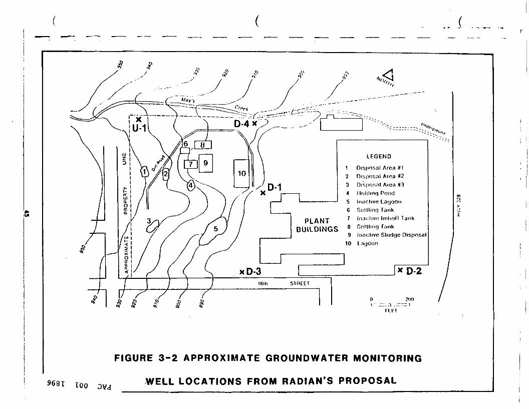
Disposal Area HIAroa «2
Dir.pos.il Aica W3I loldinq PondInactive LagoonSolllnu) TankInaclivi; hnlioll Tank
.-inkInaclivo Slud()C DisposalLnyoon
PLANTBUILDINGS
FIGURE 3-2 APPROXIMATE GROUNDWATER MONITORING
100 WELL LOCATIONS FROM RADIAN'S PROPOSAL

Each of the five wells specified would be drilled to bedrockusing a hollow stem auger. Core samples would be collected at five footintervals using a split spoon sampler. Samples would be labelled, appro-priately preserved, and stored. After drilling to total depth, wellcasings and screens would be emplaced and wells would be gravel packed andgrouted with cement to land surface.
Based on the field descriptions of the lithology and the pre-sence or absence of groundwater at each location, a determination would bemade as to which samples (or composite samples) should be analyzed.Because none of the drilling is actually through a waste disposal area, itis not likely to be necessary or cost-effective to analyze each sample.However, selected samples or composites may provide data on lateralmigration of groundwater perched above clay layers or on infiltration ofcontaminated runoff in the area.
Following well installation, the drilling locations and eleva-tions would be surveyed to an accuracy of +0.01 feet by a qualified localsurveyor for use in accurately evaluating the groundwater flow directionand subsurface geology at the site.
On the day following completion of well installation, waterlevels would be measured and groundwater samples collected from each wellusing EPA-approved sampling and analytical techniques.
Based on a review of available data from samples previouslycollected at the site, Radian recommends that the following chemicalanalyses be performed on groundwater and selected core samples collectedon-site. Core samples would be analyzed for the parameters listed inTable 3-1. Radian states that because acid extractable and base-neutralextractable organics and pesticides have not been detected (and are notexpected to be present in the wastes at the site), complete prioritypollutant analyses are not recommended and the parameters identified inTable 3-1 should encompass the range of expected contaminants. In additionto the parameters in Table 3-1, groundwater samples would also be analyzedfor the RCRA groundwater parameters, as identified in the Federal Register, ^May 19, 1980, Part 265.92 (see Table 3-2). O
oo
CO\0-J
46

TABLE 3-1. PRIORITY POLLUTANTS PROPOSED BYRADIAN FOR ANALYSIS IN CORE SAMPLESCOLLECTED AT THE FACET SITE
VOLATILE ORGANICS
Ac roleinAcrylonitrileBenzeneTolueneEthylbenzeneCarbon TetrachlorideChlorobenzene1,2-Dichloroethane1,1,1-Tr ichloroethane1,1-Dichloroethane1,1-Dichloroethylene1,1,2-Tr ichloroethane1,1,2,2-TetrachloroethaneChloroethane2-Chloroethyl vinyl etherChloroform
1.2-Dichloropropane1.3-DichloropropeneMethylene chlorideMethyl chlorideMethyl bromideBrorooformDichlorobromoethaneTr ichlorofluoronethaneDichlorodifluoromethaneChlorodibromonethaneTetrachloroethyleneTr ichloroethyleneVinyl chloride1,2-trans-Dichloroethylenebis(Chloromethyl) ether
METALS
AntimonyArsenicBerylliumCadmiumChromiumCopperLead
MercuryNickelSeleniumSilverThalliumZinc
MISCELLANEOUS
Aroclor 1016Aroclor 1221Aroclor 1232Aroclor 1242Aroclor 1248Aroclor 1254Aroclor 1260Total Cyanides
TJ>O
oO
00VO00
47
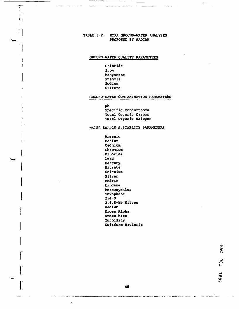
TABLE 3-2. RCRA GROUND-WATER ANALYSESPROPOSED BY RADIAN
GROUND-WATER QUALITY PARAMETERS
ChlorideIronManganesePhenolsSodiumSulfate
GROUND-WATER CONTAMINATION PARAMETERS
phSpecific ConductanceTotal Organic CarbonTotal Organic Halogen
WATER SUPPLY SUITABLITY PARAMETERS
ArsenicBariumCadmiumChromiumFluorideLeadMercuryNitrateSeleniumSilverEndrinLindaneMethoxychlorToxaphene2,4-D2,4,5-TP SilvexRadiumGross AlphaGross BetaTurbidityColiform Bacteria
noo
00vo
48
Upon completion of the chemical analyses of groundwater andcore samples, Radian will prepare a report which will be submitted toFacet, describing the results of the study and making recommendationsregarding the need for any further study or remedial action at the site.The following information will be included in the report:
o Description of subsurface lithology, including boring logs;o Assessment of site hydrogeologic conditions including discussion
of the occurrence, depth, and flow of groundwater, if present;o Map of water table elevations;o Discussion of the effects, if any, of pumping in nearby wells
on groundwater flow at the Facet site;o Presentation and interpretation of analytical data on core
samples and/or groundwater samples;o Assessment of the occurrence or potential for groundwater
contamination; ando Reconunendations for further action.
Recommended Modifications Of Radian Proposal
The following are recommendations for enhancing the Radianproposal:
1. Install wells U-1, D-3 and D-4 essentially as proposedby Radian (see Figure 3-3} but, in addition, performin-situ permeability tests to determine the permeabilityof the aquifer at the site. This would provide informationon the rate of groundwater flow through the aquifer atthe disposal site at litte additional cost. The informationwould be a valuable input to the modeling process.
2. Use the water table levels observed in these three wellsset out in a triangular pattern to plot water table contoursand determine hydraulic gradients in the vicinity of thewaste disposal areas and thus determine the basic ground-water flow direction from the area. Assume this direction tobe along the line through 0-1, D-1 and D-2. Install wells • >oD-1 and D-2 adding in-situ permeability determinations asfor wells U-1, D-3 and D-4. o
rvooo
49
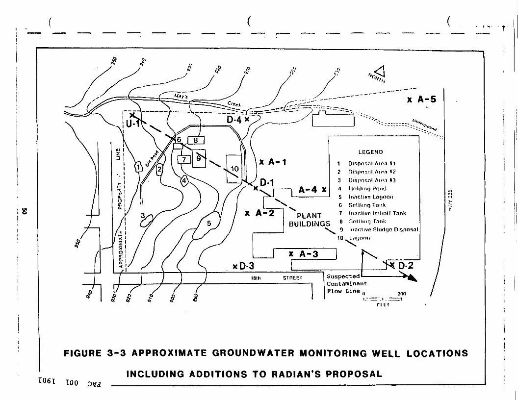
' T
PLANTBUILDINGS
x A-5
"•>„
LEGEND
Disposal Arm HIr)in|>or.;il Arm M2nisiins.il Ainn W3Inkling Pond
Inaclivn l.nrioonSolllmri TankIn.'ichvn Imhnll Tankr>nlllinn TnnkInnclivn Slii(l(|C Dispnsal
SuspectedContaminantFlow Line .. vm
n HT
FIGURE 3-3 APPROXIMATE GROUNDWATER MONITORING WELL LOCATIONS
1061 tooINCLUDING ADDITIONS TO RADIAN'S PROPOSAL

3. Add wells A-1, A-2, A-3, A-4 and A-5 to the five proposedby Radian with approximate locations as shown in Figure 3-3.Nells A-1, A-2, A-3 and A-4 would provide additional infor-mation in defining the contamination plume. Well A-5is located between U-1 and the Facet Enterprises well eastof Route 14 and is intended to provide information on waterquality changes in the direction towards that well in whichTCE contamination has been observed. No in-situ permeabilitytesting is proposed for these wells.
4. Analyze one water sample from each of the 10 wells forthe full range of priority pollutants including acid extrac-table and base-neutral extractable organics and pesticides.Contrary to Radian's claim, all three of these types ofpollutants have been detected in samples taken from thesite. In addition, the proposed sampling represents thefirst set of borehole and groundwater sampling to be under-taken on the disposal site and should be subjected to acomplete priority pollutant scan. Such a scan is alsoindicated because the character of the wastes disposed atthe site is not fully known.
5. Omit the Radian proposed analyses of core samples fromthe wells since the really significant migration of pollu-tants is likely to take place through the groundwater.
6. Omit the Radian proposed RCRA groundwater analyses sincethe analyses of real relevance to this remedial action plan,the priority pollutant scan, would be undertaken.
Model Application
The above modified Radian proposal would provide information onthe geology and hydraulic characteristics of the aquifer and locate thecontamination plume and its direction of flow on the Facet site. Informa- ^
>tion from this set of site investigations may then be input to the Cheraung oRiver Basin Groundwater Model to estimate the contamination flow path and o
o
o10
51

I location of its front in the aquifer. This would indicate the likelyextent to which the aquifer and specific wells are being contaminated andare likely to be contaminated in the future. Existing and/or new wells maybe used to sample water quality in the vicinity of the computer predictedplume and thus refine the location of the plume. With the plume locatedand characterized, a feasibility study of remedial actions may then pro-
} . ceed.i [_ Application of the model would require a review and updating; of data input used by Reisenauer (1977b). Any newly developed data on
the hydraulic characteristics of the aquifer from recent pumping testsshould be incorporated. Changes in groundwater extraction as a result ofnew and abandoned wells need to be incorporated.
The model should be run with boundaries similar to those shownin Figure 1-4 but with an appropriately wider range of flow lines beingexamined to explore the widest range of effects depending on pumping ratesof vicinity wells. For costing purposes, three computer runs have beenincluded in the hydrogeologic survey.
3.6 Surface Water Investigation
Surface water from the Facet Enterprises site is drained bytwo networks of ditches which flow to Newtown Creek as shown in Figure3-4. The first set, which drains the northern portion of the site, forms asingle ditch which is located along the plant's northern border. Thisdrainage ditch goes underground and discharges into May's Creek near Route14. May's Creek is an intermittent stream which parallels Facet's nor-thern boundary just beyond the plant property. Upon reaching the endof Facet's property. May's Creek turns south and follows Route 14 beforeturning east again and joining Newtown Creek.
Surface water collected by the plant's southern network ofditches passes through an oil separator before leaving the site via outfall002. This outfall is located at about the midpoint of the plant site'ssouthern boundary. After leaving the Facet site, this water enters an openditch and flows south eventually joining a tributary to Eldridge Lake. Thelake discharges into Diven Creek which flows east and empties into NewtownCreek, a tributary to the Chemung River.
52
vooCO

FIGURE 3-4
SURFACE WATER AND SEDIMENT SAMPLE LOCATIONS
\1-May's Creek - upstream of disposal areas2-May's Creek - downstream of disposal areas3-Facet's northern ditch - downstream of sites4-Facet's drainage ditch - across from Facet on east side of Route 3285-Facet's leachate lagoon6-Ditch receiving flow through Facet discharge 002 at 18th Street7-Ditch receiving flow through Facet discharge 002 at 14th Street8-Tributary to Eldridge Lake, downstream of its confluence with theditch that receives flow from Facet discharge 002
9-Eldridge Lake near confluence with the tributary carrying flow fromFacet discharge 002
Note: Large arrowheads indicate direction of surface water flow
oo
10o
53
i l
During previous sampling efforts within the plant boundaries,high levels of volatile organic compounds have been detected in water fromthe drainage ditches. In addition, high concentrations of metals havebeen measured in the sediments of these ditches. Additional surfacewater and sediment samples should be collected to ascertain the extentof contaminant migration from Facet through surface water and accompanyingsediment movement through drainage ditches.
A surface water sampling program is recommended that wouldutilize the set of sampling points proposed by the New York State Depart-ment of Environmental Conservation (Carol Rerrington, Memorandum toBob McCarthy, March 16, 1982). Collection of surface water and bottomsediment samples from the following locations (see Figure 3-4) are pro-posed:
1. May's Creek - upstream of disposal areas2. May's Creek - downstream of disposal areas3. Facet's northern drainage ditch - downstream of disposal
areas4. Facet's drainage ditch - across from Facet on the east
side of Route 145. Facet's leachate lagoon6. Ditch receiving flow through Facet's discharge 002 at 18th
Street7. Ditch receiving flow through Facet's discharge 002 at 14th
Street8. Tributary to Eldridge Lake, downstream of confluence with
the ditch which receives flow from Facet's discharge 0029. Eldridge Lake near confluence with the tributary carrying
flow from Facet discharge 002It is recommended that a complete priority pollutant scan be
performed on each of the samples collected rather than the more limitedlist of parameters proposed by NYSDEC for analysis in a Mobile Laboratory.This change would provide a more complete characterization of the water andwould be consistent with the parameters recommended for analysis in otherparts of the site investigation. o
o
IOo
54

The data generated by analysis of these samples would be used todetermine the extent and significance of contaminant migration from thesite. Based on these determinations, appropriate remedial measures maythen be planned.
3.7 Laboratory Analysis
Analytical support for Superfund's Hazardous Waste remedialaction investigation is routinely provided by the national ContractorLaboratory Program (CLP). This program is coordinated by VIAR (Alexandria,VA), a management consultant firm under contract to EPA's Sample ManagementOffice (SMO). All CLP analyses are performed by private laboratories ofproven ability which have won competitive contract awards. Continuedlaboratory performance is assured through ongoing quality assuranceevaulations conducted by the Environmental Monitoring and Support Labora-tory/Las Vegas (EMSL/LV). EMSL/LV is also responsible for developing allmethods, standards and protocols used by contractor laboratories. Finaldata review and evaluation is conducted by the CLP support staff withassistance from EMSL/LV.
Although the majority of samples collected can be analyzedunder the standardized laboratory protocols, the Sample Analysis Programalso provides the capability for specialized or custom analytical ser-vices. Requirements for tissue, non-priority pollutant quantification orother types of analyses not yet provided by standardized laboratory con-tracts may be scheduled under the Special Analytical Services (SAS) pro-gram. All analyses performed under this program are subject to the samequality assurance and data review requirements stipulated for standardanalyses.
A list of samples and analyses required for the detailed siteinvestigations is presented in Table 3-3. As noted previously, somesamples in addition to those listed in Table 3-3 would be collected but notimmediately analyzed. Certain of these samples may be analyzed later
^depending on the results of the planned sample analyses and observations in >the field.
oo
55

TABLE 3-3
FACET ENTERPRISES DETAILED SITE INVESTIGATION - SAMPLES REQUIRINGLABORATORY ANALYSES
SAMPLE TYPEt OFSAMPLES ANALYSIS REQUIRED
RELATEDINVESTIGATION SAMPLE LOCATION
AIR - Participates- Semi-Volatiles- Gaseous Compounds
Safety & Health Up-wind ofdisposal areas
AIR
AIR
AIR
SEDIMENT
18
40
10
SOIL
- Particulates- Semi-Volatiles- Gaseous Compounds
- Particulates- Semi-Volatiles- Gaseous Compounds
- Particulates- Semi-Volatiles- Gaseous Compounds
Priority PollutantScan
Priority PollutantScan
Safety & Health
Safety & Health
Safety t Health
Surface Hater
Identification andCharacterization ofDisposal Areas
At disposal sites
Downwind ofdisposal sites
Personal sampleby Safety andHealth Officer
Facet drainageditches and tribu-taries to NewtownCreek
One composite fromeach waste disposalarea
loo

..... r
TABLE 3-3 (Continued)
FACET ENTERPRISES DETAILED SITE INVESTIGATION - SAMPLES REQUIRINGLABORATORY ANALYSES
SAMPLE TYPE* OPSAMPLES ANALYSIS REQUIRED
RELATEDINVESTIGATION SAMPLE LOCATION
HATER
HATER
HATER
10
10
Priority PollutantScan
Priority PollutantScan
Priority PollutantScan
Identification andCharacterization ofDisposal Areas
Hydrogeolog ical
Surface Hater
One groundwater com-posite from fourboreholes at eachwaste disposal area
One groundwaterfrom each ground-water monitoringwell
Facet drainageditches and tribu-taries to Newtown Creek
806t too
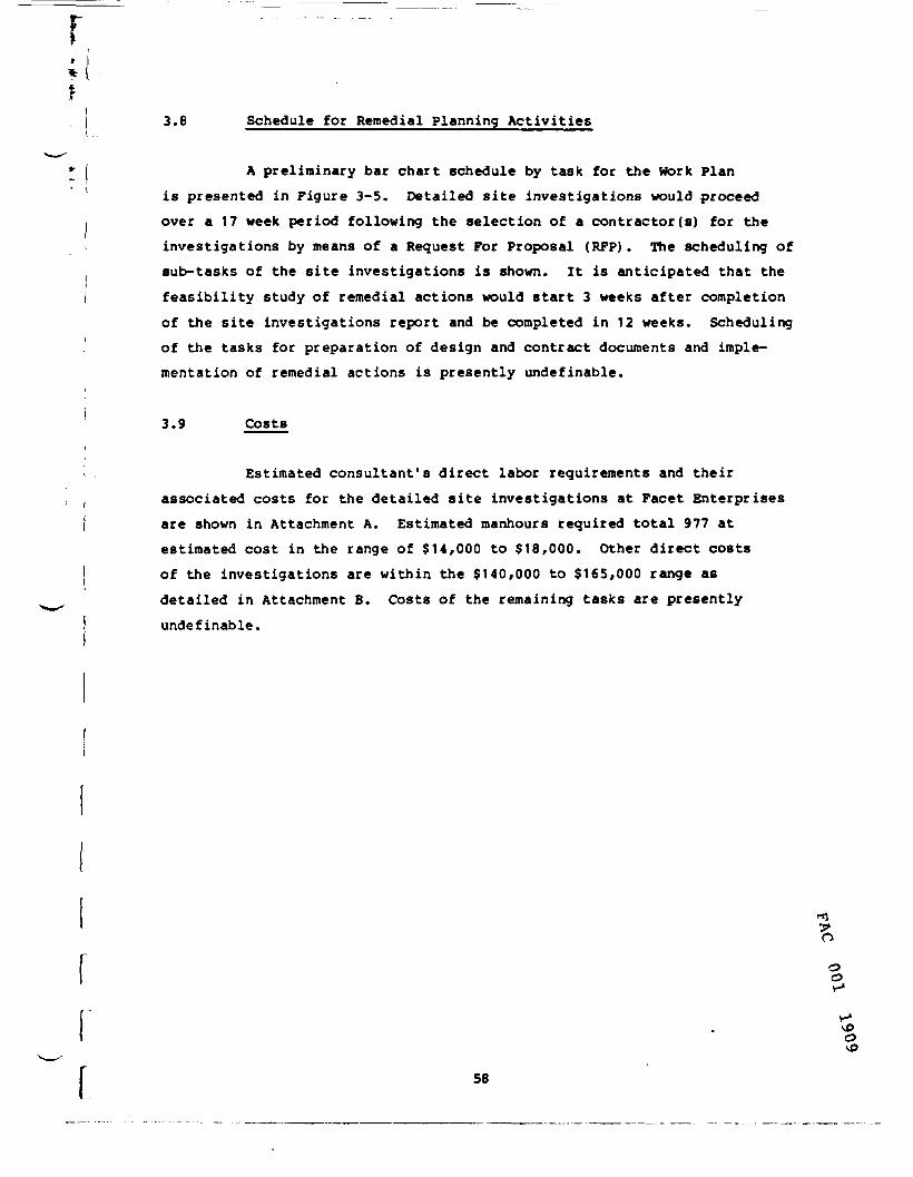
rtI 3.8 Schedule for Remedial Planning Activities
I A preliminary bar chart schedule by task for the Work Planis presented in Figure 3-5. Detailed site investigations would proceed
I over a 17 week period following the selection of a contractor(s) for the< investigations by means of a Request For Proposal (RFP). The scheduling of
sub-tasks of the site investigations is shown. It is anticipated that theI feasibility study of remedial actions would start 3 weeks after completion
of the site investigations report and be completed in 12 weeks. Schedulingj of the tasks for preparation of design and contract documents and imple-
mentation of remedial actions is presently indefinable.
3.9 Costs/i, Estimated consultant's direct labor requirements and their
associated costs for the detailed site investigations at Facet Enterprisesj are shown in Attachment A. Estimated manhours required total 977 at
estimated cost in the range of $14,000 to $18,000. Other direct costsof the investigations are within the $140,000 to $165,000 range asdetailed in Attachment B. Costs of the remaining tasks are presentlyundefinable.
SB
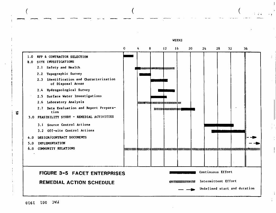
WEEKS
12 16 20 24 28 32 36
1.0 RFP & CONTRACTOR SELECTION2.0 SITE INVESTIGATIONS
2.1 Safety and Health
2.2 Topographic Survey2.3 Identification and Characterization
of Disposal Areas
2.4 Hydrogeological Survey
2.5 Surface Water Investigations2.6 Laboratory Analysis2.7 Data Evaluation and Report Prepara-
tion3.0 FEASIBILITY STUDY - REMEDIAL ACTIVITIES
3.1 Source Control Actions3.2 Off-site Control Actions
4.0 DESIGN/CONTRACT DOCUMENTS
5.0 IMPLEMENTATION6.0 COMMUNITY RELATIONS
•••
•
Illllllllllllll
•minium
Illlllllllllllll
Illllllllllllll
mmimniiM
—
mmmmi
•
•PHM
--Tiiiiiimmiiliiiiiinii
Illllllllllllll
immiinmIllllllllllllll
Illllllllllllll
millllMBl
Illlllllllllllll
•
Illlllllllllllll
•••"•• | | |
Illlllllllllllll Illlllllllllllll Illlllllllllllllll
--»•- -^
iiniiiiiiiiiinii
FIGURE 3-5 FACET ENTERPRISES wmmmmmm continuous Ef for t
REMEDIAL ACTION SCHEDULE Illllllllllllllllllllllllllllllll Intermittent E f fo r t
__ ^ Undefined start and duration
OT6I 100

FACET ENTERPRISES REFERENCES
Althoff, W.F., Cleary, R.W., and Roux, P.H., September, 1981. AquiferDecontamination for Volatile Organics: A Case History. Groundwater,September - October, 1981, Volume 19, Number 5.
Finster, Bruce, August 28, 1980. Memorandum to Bruce Butler, RegionalWater Engineer - subj.: Contamination of the Kentucky Avenue wellwith TCE. New York State Department of Environmental Conservation,Avon, New York.
Hazen and Sawyer, April, 1969. Report on Comprehensive Water Supply Studyfor Chemung County, New York. New York State Department of Health,Albany, New York.
Herrington, Carol, March 25, 1981a. Sampling Inspection Report - FacetEnterprises, Inc., New York State Department of EnvironmentalConservation, Avon, New York.
Herrington, Carol, August 7, 1981b. Facet Sampling Data. New York StateDepartment of Environmental Conservation, Avon, New York.
Herrington, Carol, March 16, 1982. Memorandum to Bob McCarty, AssociateSanitary Engineer - subj.: Use of Mobile Lab for a Sampling Projectin Region 8. New York State Department of Environmental Conservation,Avon, New York.
Leichter, Irving, June 30, 1980. Hazardous Waste Site Inspection Report -Facet Enterprises, Elmira Heights, New York. Fred C. Hart Associates,Inc., Newark, New Jersey.
Miller, T.S., A.D. Randall, J.L. Belli, and R.V. Alien, 1982. Geohydrologyof the Valley - Fill Aquifer in the Elmira Area, Chemung County,New York. Open File Report 82-110, Department of the Interior,United States Geological Survey. Albany, New York.
New York State Department of Environmental Conservation, April 11, 1979.Information Dossier 79.6. Avon, New York.
Radian Corporation, June 10, 1982. Revised Proposal to Perform anInvestigation of Geology and Groundwater Conditions at FacetEnterprises, Elmira, New York.
v*vP
60

iI! I! 1 Reisenauer, A.E., November, 1977a. Groundwater Model Application to the
Chemung River Basin 208 Study Area, New York State. Southern Tier•*• Central Regional Planning and Development Board. Battelle Pacific! I Northwest Laboratories, Richland, Washington.• I
Reisenauer, A.E., November, 1977b. Groundwater Model Test Cases for the/ Chemung River Basin 208 Study Area, New York State. Southern Tier
: I, Central Regional Planning and Development Board. Battelle PacificNorthwest Laboratories, Richland, Washington.
I Tolraan, Ballestero, Beck and Emrich, August, 1978. Guidance Manual for• '• Minimizing Pollution from Waste Disposal Sites. EPA 600/2-78-142.
Cincinnati, Ohio.
United States Environmental Protection Agency, July, 1982a. Site Investi-gation Facet Enterprises, Inc. Elmira Heights, New York - InterimReport. TS-PIC-2030. Las Vegas, Nevada.
United States Environmental Protection Agency, July 1982a. Facet Enter-prises, Inc. Site Investigation - Elmira Heights, New York - InterimReport. TS-PIC-2030. Las Vegas, Nevada.
United states Environmental Proteciton Agency-Region II, November 1982b.Letter to Camp Dresser and McKee, Inc.: Comments on Draft FacetRemedial Action Master Plan. New York, New York.
United States Environmental Protection Agency, October 1982c. FacetEnterprises, Inc. Site Investigation - Elmira Heights, New York.TS-PIC-82030. Las Vegas, Nevada.
I
61
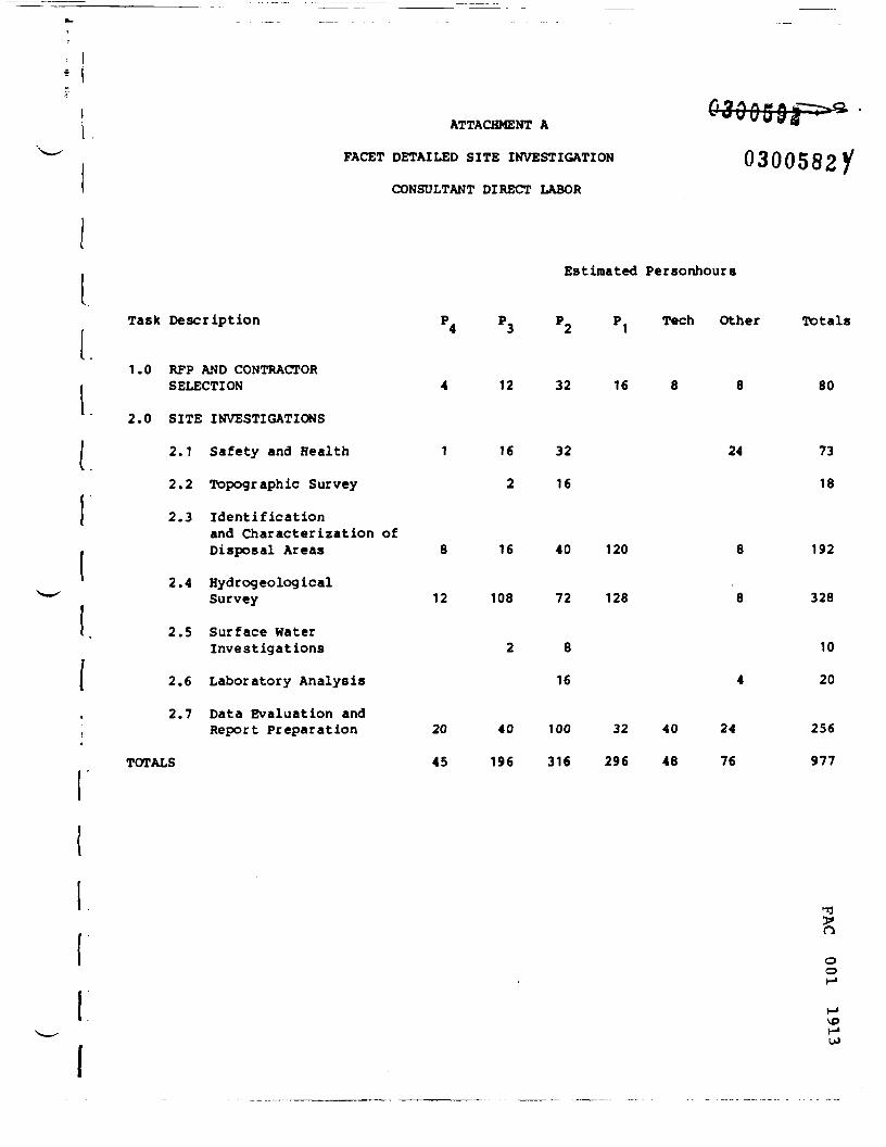
ATTACHMENT A
FACET DETAILED SITE INVESTIGATION
CONSULTANT DIRECT LABOR
0300582/
Estimated Personhours
Task Description
1.0 RFP AND CONTRACTORSELECTION
2.0 SITE INVESTIGATIONS
2.1 Safety and Health
2.2 Topographic Survey
2.3 Identificationand Characterization ofDisposal Areas
2.4 Hydr©geologicalSurvey
2.5 Surface HaterInvestigations
2.6 Laboratory Analysis
2.7 Data Evaluation andReport Preparation
TOTALS
P4 P3 P2 PI Tech Other Totals
12 32 16 80
1
8
12
20
45
16
2
16
108
2
40
196
32 24
16
40 120 8
72 128 8
8
16 4
100 32 40 24
316 296 48 76
73
18
192
328
10
20
256
977
oo

r
i ,
Task Description
Rates ($ per hour)
ATTACHMENT A (continued)
FACET DETAILED SITE INVESTIGATION
CONSULTANT DIRECT LABOR COSTS
03005822
Estimated Cost ($)
P4 P3 P2 PI Tech Other Total
23 18 15 13 10
1.0 RFP AND CONTRACTORSELECTION
2.0 SITE INVESTIGATIONS
2.1 Safety and Health
2.2 Topographic Survey
2.3 Identification andCharacterization ofDisposal Areas
2.4 HydrogeologicalSurvey
2.5 Surface HaterInvestigations
2.6 Laboratory Analysis
2.7 Data Evaluation andReport Preparation
Totals
Range
92 216 480 208 80 56
23 288 480
36 240
184 288 600 1560
276 1944 1080 1664
36 120
240
168
56
56
28
1132
959
276
2688
5020
156
268
460 720 1500 416 400 168 3664
1035 3528 4740 3848 480 532 14,163
$14,000 - $16,000
ooo
vo

ATTACHMENT B Q30Q59
FACET DETAILED SITE INVESTIGATION P^rtrtCO
OTHER DIRECT COSTS
TASK Cost Range ($)
1.0 RFP i Contractor Selection $350 - $550
2.1 Safety and Health10 Baseline Medical Profiles 9 $150 $1,5005 Medical Examinations 9 $350 1,750Sample Collection and Surveys
45 days x 8 hours/day 9 $15/hr40 hours - P § $23/hrDirect Labor (DL)Total Labor Cost * D.L. x 2.2Contingency - 20%Subtotal $16,685
Total Cost - Safety and Health $19,935Range - Safety and Health $18,000 - $22,000
2.2 Topographic Survey (Based on Information $3,000 - $5,000from Photoscience, Inc.)
2.3 Identification and Characterization of Disposal Areas- 5 sites x 4 holes per site x 30 ft
depth per hole with sampling «600 ft 9 $6.50/ft $3,900
- 5 sites x 12 holes per site x 10 ftdepth per hole with sampling -600 ft 9 $6.50/ft 3,9005 sites x 4 GW samples per site *20 GW samples § $10 200
- 5 sites x 4 holes per site x 2 splitspoon samples per hole « 40 samples0 $12 480
- Surveying, Layout, and Levelling3 persons x 3 days
- Investigation of tunnel on site- Mobilization- Report - 40 hrs 9 $23/hr x 2.2- Subtotal ^- Contingencies 20% 2,653 O
- Total Cost - Identification and gCharacterization of Disposal Areas $19,917 i~>
- Range - identification and Charac-terization of Disposal Areas $19,000 - $22,000 <-"\o

ATTACHMENT B (Continued)
FACET DETAILED SITE INVESTIGATION 0300582S&
! OTHER DIRECT COSTS• I .it I TASK Cost Range ($)! I 2.4 Hydrogeologic Survey and Groundwater Modelling
Hydrogeologic SurveyMobilization $ 900Construct 10 wells 9 $25/ft. 20,000Develop 10 wells 9 $100 each 1,000Insitu Permeability Testing5 wells: 8 hrs 9 $90/hr 720
Surveying, Layout, and Levelling3 persons x 3 days
10 wells x 1 GW Sample 9 $10Report - 40 hrs 9 $23/hr x 2.2SubtotalContingencies 20% _____Total Cost - Hydrogeologic Survey $32,285
- Groundwater ModellingData Collection and Review
P - 24 hours 9 $23/hr 552Tech - 40 hours 9 $15/hr 600
Running Model (3 runs 9 2 days each)P - 48 hrs e $23/hr 1,104Total DL $ 2,256
Total Labor Cost - 2.2 x DL 4,963Computer Time 100Miscellaneous ODCs 150Subtotal $ 5,213
Contingencies - 20% 1,043Total Cost - Groundwater Modelling $ 6,256
Total Cost - Hydrogeologic Survey $38,541and Groundwater Modelling
Range - Hydrogeologic Survey andGroundwater Modelling $37,000 - $43,000
2.5 Surface Water InvestigationCollect 10 surface water t 10 sediment
samplesP - 16 hrs « $23 $ 368Tech - 40 hrs 9 $15 600 2
- DL $ 968 OTotal Labor Cost - DL x 2.2 2,130Miscellaneous - Transport, ODCs 170 ®Subtotal $ 2,300 t->Contingencies - 20% 460Total Cost - Surface Water £Investigation $ 2,760 t-,
Range - Surface Water Investigation $2,000 - $4,000 <*

I Ii
FACET DETAILED SITE INVESTIGATION
OTHER DIRECT COSTS
i1 L ATTACHMENT B (Continued) ..
0300582ft:
TASK Cost Range ($)
2.6 Laboratory AnalysisSafety and Health
24 air samples for particulates§ $30 $ 72024 air samples for semi-volatiles§ $40 96024 air samples for gaseous compoundse $70 1,68040 personal air samples for particu-lates § $30 1,20040 personal air samples for semi-volatiles « $40 1,60040 personal air samples for gaseouscompounds § $70 2,800Total Cost Safety and Health LabAnalysis $ 8,960
Identification and Characterization' 5 sites x 2 priority pollutantI scans (GW, waste) 9 $1800 $18,000
Hydrogeological Survey{ 10 GW priority pollutant
scans g $1800 $18,000- Surface Water Investigation
10 water & 10 sediment prioritypollutant scans 9 $1800 $36,000
Total Cost - Laboratory Analysis $80,960Range - Laboratory Analysis $80,000 - $84,000
i Total Cost Range - Detailed Site Investigation (ODC's only) $160,000 - $185,000
i
oo

« i
oCO
00roo
1-1CHEMUNG RIVER BASIN
8161 TOO

HI
EXPLAHATIOH
A r t i f i c i a l f i l l
Op*n-Mt*r Area
A l l u v i a l sand and qrawl: sttean, fan, channel, andtviraci* deposits of poslqlacial to recent aqei hlqhprrmeahi1ity
Alluvial silt and (or I very fine sand) floodplalndeposits of postqlacial to recent aqei low per-neability
Lake silt and clay: offshore deposits in proqlactalor pnstqlacial lakes; thin bedded to Massive; lowperneability
Lake silt and fine sand; offshore deposits In pro-qlacial or postqlacial lakes; thin bedded to «as-Slve; low to Moderate pernieabil Ity
Lodgement t l l l i qlaclal deposits of unstratlfledclay, silt, and sand, with occasional pebbles, cob-bles, and boulders deposited at base of qlacieri lowpermeability
Outwash sand and qravel; swltwater deposits; stra-tified and well sorted; hiqh peraieabllity
(we and kasw terrace sand and qravel; ice-contactdeposits: some sortlnq and secondary calclte ce-mentation; hiqh persteabil Ity
Horalnal t i l l ; qenerally stony with llKlted ad«l«-ture of poorly sorted qravel deposited at edqe ofIce sheet; low perieablIIty
Till over bedrock lundlfferentlated)i qlaclal depo-Sltes of unstratlfled silt and sand, w i t h occasionalpehb'es, cobbles, and boulders, qenerally less thanJO feet thick; low permeability
Bedrock (undlfferentlated); shale and stltstone; lowto moderate permeability In fractures and ]oints
GEOLOGIC COKTACT--dashed where appronimately located
LINE OF SECTIO»--see sheet 2, 'Geologic iectlon«-
AQUIFER BOUNDARY—dashed where full e«tent of aqui-fer is not shown: aquifer entends up some smallvalleys and up and oojn valley of principal stream.Aquifer Is continuous with Corninq aquifer to west
EXHIBIT 1-2
SURFICIAL GEOLOGY - NEWTOWN CREEK AQUIFER
Source: MIMtr •! al. 1982
6*6T TOO

£I58
z•t
ra
EXHIBI'
Sourc
EXPLANATION
0 rArtificial fill V-
*~Ipml Peat, marl, muck, and clayi bag deposits of postglacial toL- — 1 recent aget low permeability <", —— , 0. 150-|alg| Alluvial sand and gravel; stream, fan, channel, and terrace ^' —— ' deposits of postglacial to recent age; high permeability O qrw-y
lalsl Alluvial silt and (or) very fine sand: floodplain deposits of ^• —— ' postglacial to recent agei low permeability z 850"
1 —— 1 ***llssl Lake silt and fine sand; offshore deposits In proglaclal or * Rod
permeability < ?5
llsc Lake silt and clayt offshore deposits in proglacial or post- {Jj' —— glacial lakes) thin bedded to massive: low permeability u. 700'
0 Outwash sand and gravel) meltwater deposits) stratified and "V ,,.well sorted) high permeability UJ 0;>U
Iksgl Rame and kame terrace sand and gravel; ice-contact deposits; ^ 600*
ability < 55O
0 Horalnal till; generally stony with limited admixture ofpoorly sorted gravel deposited at edge of Ice sheet; lowpermeability
1 —— |lltl Lodgement tllli glacial deposits of unstrattfled clay, silt.
^J —— ' and sand, with occasional pebbles, cobbles, and boulders
— 1 r I Bedrock lundlfferent latedl i shale and siltstone; lowtomoder-' —— ' ate permeability in fractures and joints IOOO-
,- —— — -* GEOLOGIC COHTACT--dashed where apprommately located ISO
....... WATER TABLE *)0°
HSO-
V///S///// WIHCIWO, AQUIFER -Q_
/////
750
700r 1-3 CROSS SECTIONS THROUGH THE NEWTOWN CREEK AQUIFER
•so
e: Miller at al. 193?
c 5
J "S I I ~l *^ «J^P 0 ™ •
y, ~> "y^ ^ M **0 JO 2 ? Qo. 0.0.0. °- «j
X^ J? •• S"T 8 1^>\. ' i -> ri » — -a ' *S
\^>^_?7L_^^ als S^N '»i xll'* v ' >-^«-rr. . ."T,/~T. .A»-vr* ^^^ *T~^ 1 /• \/ I/ I' ^
* » i
\ s /\ ^^^ _x ' ,r \ '
\s " /r^ ^ -
~?"»^es1C
D 1 *- ^"!^ ?r ^"f-ji v» is.
V\ ?5«8 • f£ 5?
Zv^sT"1 — [^Toso — «-N<^\A i^ ~^~~^z^r'~ ~ ^ •'r N*^.;^S iss i' ^<y tT^- -~<~-Cf'//
r ~ '
,,,
r? (? ?VlVi ^ ^
-5-J O*i*«^'7/^'C^* /^
tyu
Iir
•«jy
o
to«•
/ //OS3 >r
...
-j'
'
150
100
-QtnDjU
-JOO
•750
•700
-6SO
-Wo
,Q
rIOOO
ks9-w
^-TO
</-,«y'r "fo°
-TV)
-700
0261 TOO
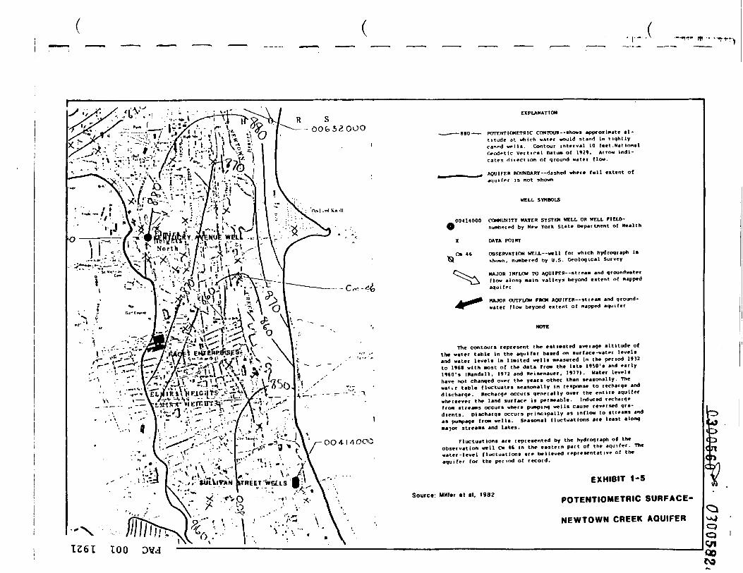
—IT" If) - "~1
R S- O O f o 3 2 0 O O
OO 4-1 4 OOC
EXPLANATION
porrHTio«rr«ic coMTOU«--«hovititude at which v*t?r would stand In tightlyca*>-d w-IU Contour intvivil 10 le«t .M«t ion«lGrodrtlc Vrr t ica l Datum of 1111. Arrow Indi-cates direction of qround water flow.
AQUIFER BOUNDARY--d»shed whet* full Mtint ofaqulffr is not shown
WELL SYMBOLS
00414000 COMMUNITY WATER SYSTEM WELL OR WELL FIELD-) numbered by New York State Department of Health
X DATA POINT
Cm 46 OBSERVATION WELL—well for which hydroqraph liI shown, numbered by U.S. Geological Survey
MAJOR INFLOW TO AQUlFER--stream and qroundwaterflow along main valleys beyond entenl of mappedaqui fer
MAJOR OUTFLOW FROM AQUIFER—stream and qround-water flow beyond extent of napped aquifer
The contours represent the estimated average altitude ofthe water table In the aquifer based on surface-water levelsand water levels In limited wells measured In the period 1»32to Ittt with most of the data from the late HSO's and ea lyHSO's IRandall. 1»7J and Reisenauer, 1»77). Water levelhave not changed over the years other than seasonally. Thwat i r table fluctuates seasonally In response to recharqe anddischarge. Recharge occurs generally over the entire aqu ferwhereever the land surface is permeable. Induced recharqfrom streams occurs where pumping wells cause reversed qr -dients. Dlscharqe occurs principally as Inflow to streamas pumpage from wells, seasonal fluctuations are least amajor streams and lakes.
onq
Fluctuations are represented by the hydroqraph ol theobservation well Cm 4« In the eastern part of the aquifer. Thewater-level fluctuations are believed representative of theaquifer for the pel iod of record.
Source Miller cl il. 1982
EXHIBIT 1-5
POTENTIOMETRIC SURFACE-
NEWTOWN CREEK AQUIFER
1261 TOO

' ''/1> • / - • ' . - '• • . - v! V •• , -~_X '-' i 7 /I "•"-.'- - I \ tf ^K
, £r -1 /=-^.-£--»v-'^- ' • * * / • • - '- 1 " - x -• :•••• : ' • • -:•«•». <' • V
• - . , -.'": -U-v
F»^irlh
•\^ \ tv
T, \ \• V v: S
EXPLANATtON
ESTIMATED WATER YIELD FROM A PROPERLY CONSTRUCTED WELL,in gallons per minute
[T] L*-5S than SO
[7] 50 to SCO
Q] SOO to 1.000
[T] Gr^ati-r than 1,000
BCHfNnARY OF HELL-YIELD UNITS--apprOK i«at«lylocated
„ AQUIFER BOUNpANY-'dashed wher* Full extent ofaqui f*r is not shown
0041400 COfWUNITY WATER SYSTEM WELL OR WELL TIELD-\ numbered by Hew York State Department of Health
X DATA POINT
Map !• based on data fro» wells (Randall, 19^2}t 20 pump-V -j '"^a^x"",!*'* V'.V ' • "N O | -- - '"9 tests, and specific capacttie
,*^' 7"*) '."'• i \ ^ *J- \ *-'-,' 1 tants for public water and indust\ \ ,t^-t •i-".XT«.% .- • -»J|? • O 1 * transmissivity map constructed
.* .i — '' -r 1 \* -• \' '» f *•-':' * L £ of the area is considered low yie"•'•""•" V r.riiV<; *i- '-'•,«"» •• " ' ^ "'- » -• thickness of the more perae ble •
'JkW*Vv • ; - "^-- \— V •* — ( ^— " ' '* "C0"' •<*i«ent to Urge tream
t"|RV "11 ETC ITT 5* "J+ \ ' ' "" " '"""' water fro* the stream occur unde%. . *l -1* ^ " ^ 5' " ** " \ * ' -^» •" ' y i e l dsa reon l yen t imates o the• '-' ll * . *" " — •"• ' ft.-' * • ' ) "2 \ , individual wells completed n the
~^<~?*f**l '*' "•' ^V ; * " *I J- n-" \\ ' r- OO 4 \ 4 OOO
vS .:."-'%^<
from engineering con sol -ial water supplies, and fromy Reisenauer ll»77|. Mostd because of the relativete r ta l . High yields general-where Induced recharge ofpumping conditions. Wfll
aximuHi long-term yields ofaquifers.
EXHIBIT 1-6
WELL YIELD-
NEWTOWN CREEK AQUIFER
Source Miller •! al. 198?
-0300562^-
^-i I 03005827/! '-
APPENDIX A
r
O
oo
Ul

r
I L.y.i ?_-- , '•ovr "i c
Submitted to:Mr David V. JacksonFacet Enterprises Inc.
7030 South Yale, Suite 800Tulsa, Oklahoma
Prepared by:Radian Corporation
o
10 June 1982 §
vo
i . o I:;TKODUC~IO:: . . . . . . . . . . . . . . . . . . . . 1
2 . 0 ?ZG:C::.-J. GICLCGY . . . . . . . . . . . . . . . . . . 3
A.O PROPOSED FIELD rF.OGP.AM . . . . . . . . . . . . . . . -
5.0 SA:--PLE COLLECTION A:;D CHEMICAL ANALYSIS . . . . . . 15
6.0 HZPORT TO FACET . . . . . . . . . . . . . . . . . . 18
noo
IO
ii S

1.0 INTRODUCTION
On 22 February 1P£2, an initial r.eeting vas held be-tween Facet Enterprises and E?A Region II personnel regardingthe status and need for further action at an inactive waste dis-posal site on the Facet property in Ilr.ira, "=-.: Ycrk which wasformerly cvr.ed and operated by Bencix Aviation, Inc. In respcr.seto these discussions, F.edian Corporation, under contract toFacet, prepared a plan for collection cf cara on geology andrrrur. c-vrater conditions at the site. This plan is designed ~crrcvice si te -specif i c inf ci— .a tier. frcr. -.rhich an assessr.ent canre race as to the occurrence and potential fcr (or existence of)crr.tarlnation of ground water in the area. Sasec on the resultsof this study, Radian- will evaluate the need for re— .edial acticnat the site and reco~- end alternatives for such action as isdetermined to be necessary. Following review of the proposalby EPA, an additional meeting vas held on 12 Hay 1982 betweenrepresentatives of Facet, Radian, and EPA technical and enforce-ment personnel. In response to cements discussed at that meet-ing and transmitted to Radian by letter dated 18 Nay 1982, Radianhas prepared a revised proposal for studies at the site.
The proposed data collection plan consists of a pro-gram of coring, monitoring well installation, sampling, andchemical analysis to determine the following:
• subsurface lithology;
i• presence or absence of ground vater;
• depth to oround water, if present;n
• ground-water flow directions; 0o
<T\

CMOl
oo
uss
I1
53 3 r .in. 3 CTl 3 ZO 30U3SC3 J.O 33U9S3:td ' •L

fc-
I• 2.0 KZGIGSAL GEOLOGY
L c e t si te is I cca t ec on tr.e -.-rest sice cr tne•Cewtcwn Creek valley in Ilr.ira H e i g h t s , !^e-.>- York. Glac ia l out-wash and alluvium consist ing prir.arily of i n t i r r edded gravel,sand, silt, and clay ccrn^rise the valley fil l deposits (Figure2-1). levcr.iar.-age r.arine shales and sil tstcr.es cf the lever"/rest 7alls Group underlie the glacial ~=ttr i = ls. Bedrock cut-crops f~rr. the p rcn inen t hills on e i ther r i d e of the val ley.
Accc rc inz tc re r i r r . = _ U . S . G £ C _ C ' ~ i c a _ Survey cata ,certr. tc t = crcc.< "."itr.in the va_l = v in tr.e Z_r_ i r a .-.eii.'.ts area
alcr.g the v:est sice of the valley at a dep-'r. cf 70-100 feet .r.cvrever, because available geological data are regional inna tu re , the geologic condit ions beneath the ~acet disposalsites are not specifically knovn. Because the disposal areasare on the extreme vestem edge of the valley, at approximatelythe point ;chere a break in slope occurs, it is -unknovm whethera significant thickness of glacial material underlies the site(see Figure 2-1). The slope break suggests that the site naylie near the contact between bedrock and glacial deposits.
Ground water in the area occurs principally in uncon-solidated sand and gravels within the valley fill deposi ts .Ground water is found under artesian and water table conditions,typically at depths of several tens of feet or less. Regionalground-water flow is generally north to south (Figure 2-2) .The consolidated bedrock is generally not considered an aquiferbut -:ay locally yield snail quant i t ies of water . The occurrenceof ground water beneath the Facet site and its relationship tothe regional ground water system is not known.
oo
IOto00
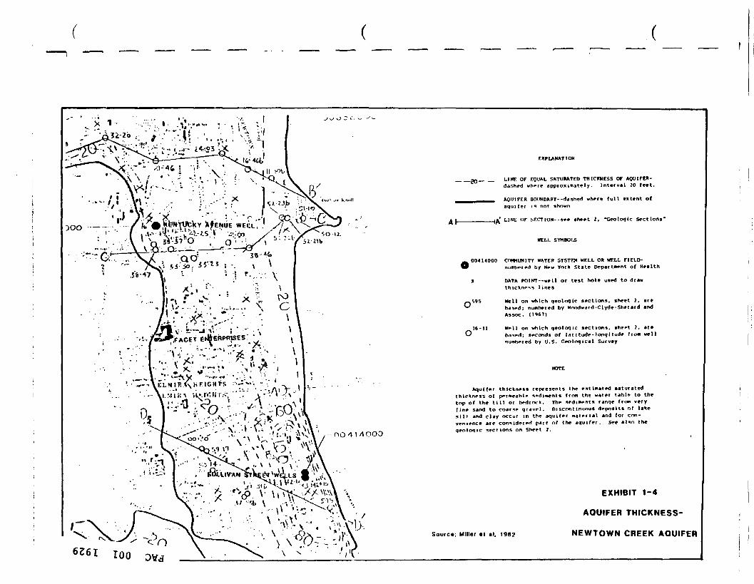
,>S>.\ • / • ! ' \ : ^sJ II VA.AW ' M - • ' < • > : , ?' V^Vl
EXPLANATION
_„_ _ LINT OF EQUAL SATURATED THICKNESS OFdar.hed where approximately. Interval 20 feet.
AQUIFER BOUNDARY--dashed where f u l l e«tent ofaqui fer is not shown
__ |» ' LINE OF SF.CTION--SM »he*t 2, "Geologic Sections"
HELL SYMBOLS
DO 4 \ A O O O
00414000 CnwUNITV HATER SYSTPM HELL OR WELL FIELD-I numbered by New York State Department of Health
X DATA POIWT--wel l or test hole used to dtawIruchnrss l ines
•*l>95 Hell on which qeoloqlc sections, sheet 2, are•^ banedi numhered by Hnndward-Clyde-Sherard and
Assoc.
Hell on which geologic sections, sheet 2. alebased; seconds of lat i tude-lonqitude from wellnumbered by U . S . Geological Survey
Aquifer thickness represents the estimated saturatedthickness of permeable sediments from the water table to thetop of the t i l l or bedrock. The sediments ranqe from veryf i n e sand to coarse q r a v e l . Discontinuous deposits of lakes i l t and clay occur in the aquifer m a t e r i a l and for con-venience are considered part of the aquifer. See also theqeoloqic sections on Sheet 2.
Source: Miller •! al. 198?
EXHIBIT 1-4
AQUIFER THICKNESS-
NEWTOWN CREEK AQUIFER
6261 100
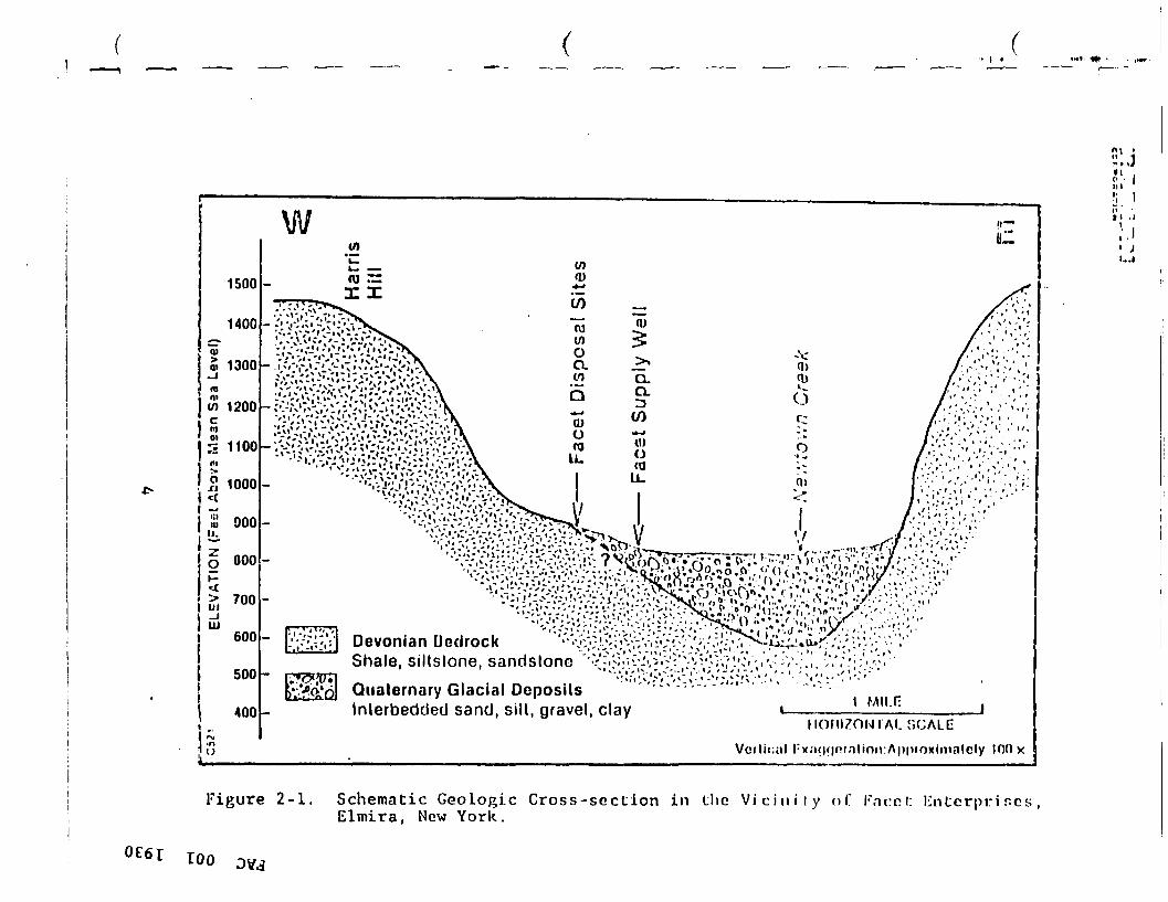
Jo o
c ••{ CD NJ
R c
n(-•
n3
~i-1-
roM
301
BJ
raQ o n >t o w en i en ra n O ra V) r>
C5?
'EL
EVA
TIO
N (F
eet A
bov»
Msa
n Se
a Le
vet)
:—
Face
t D
ispo
sal S
ites
^^•^
^g^^-—
— F
acet
Sup
ply
Wel
l
•;'r-"j
r----T
i:."-.T
c5i
-^ :'•
!'-i*
^«':
C.'^
~~
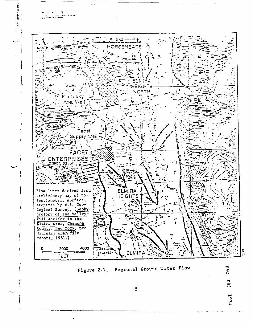
ft»
fc
i
M:~J.~'
-• Kentucky
a V/'^-^r V *•:v -. -j|
Flov lines derived from '";.\-.:preliminary nap of po- , . . nc ivanojter.tionetric surface, rf I I ' ' ' -*^^prepared by U.S. Geo- |.;> !.-/' / f ^^^.logical Survey, (Geohy- ;•crology of the Valley-Fill Acu i f e r in theElirdra area. CheaungCounty, New York., pre- plizinary open filereport, 1981.)
Figure 2-2. Regional Ground Water Flow.

Design of the f ield progra- desc r ibed below is ai...= dat obtaining information on si t e - s t e c i f i c gec log ic anc r.ydro-Cicondit ions at the Facet s i te . B a s e d or. the resul ts or tr.is s f.an assessment can be -ace as to the occurrence or potential fo:o f f - s i t e nitration of contaminants in gr:-jnc vater.
oo
voU)

.. 3
3.0 DZSIG:: OF ;-:O:;ITGRI::G •.•:ELL NE"•::•?:•:
Radian proposes to install five r.cr.i torir.g wells atthe site. Figure 3-1 is a sketch r.ap of the site shoving approMi~ = te locations of. the proposed veils. !-!cnitcr veils locationsvrere se l ec tee based on the folloving ccnsi dera t ions:
o s t i o n relative tr V.ncv— cis-csal areas
• .-.-parent grsur.c water r _ ~ v c i rec t^cns , ^asec or.inference from regional c = ta;
• Drill rig access; and
• Location of Facet prcper ty lines.
Exact locations will be determined at the initiation of fieldactivities, based on several factors including access andclearance from utilities. Because of the age of .this facility,composite snaps showing locations of underground utilities in thearea of concern are not available. However, available recordswill be reviewed and appropriate plant personnel consulted priorto initiation of drilling.
Well U-l is located to be upgradient of all disposalactivities at the site. Well U-l will be situated as close aspractical to Facet's northwest property comer and to elevation940 feet. Data from this well will represent background condi-tions. Wells D-l, D-2, D-3 and D-4 are downgradient wells.Although regional ground-water flow in the Newtown Creek Valleyis north-south, there could be an easterly co-.ponent to flow atthe Facet property. The four downgradient wells will be si tuatedto intercept any ground water flowing northeast, east, southeast,or south from the site.
10u>CO

PLANTBUILDINGS
12n•ir^
d7I)9
10
LEGEND
Dir.|>or,;il Ar«n ff I«2
llolllllMI I'f.M.I
hi;ir.livi< I n(|onnSrliliiui I linkln.ic live Inilioll TnnUr,(-llllii(| r.-ink
I ;i(|ooii
« D-2
rr.fcr
Figure 3-1. Approximate Locations of Propor.rd Hnnilnr Uc I I s/Trn I: HorJnj-.r.
TOO

4.0 PROPOSED FIELD 'KOG?.-_X
Eased on available dita en gec lcgy ar.d hvdrcgeolcgvrear the site, Radian has desigr.ed a coring.'~o~i.tor veil programto evaluate the scil/grcur.d-vater conditions and to deterr.ine ifthe vaste disposal site has a f f ec t ed the subsurface scils ar.d/orgrcurd-v.-ater quality. Xor.itcr veils vere designed •.•:ith ccr.sider-ation of drilling r.ethocs and -.aterials tc provide high qualitysar.ples for chenical ar .a lys is . Qua l i f i ed d r i l l ing con t rac to r sand surveyors have been iden t i f i ed and cc;t e s t i m a t e s cb:ained.
A F.edian hydroreclogist vill be provided for the fieldcoordination, and supervision cf the drilling/installation activ-ities. The hycrcgeologist vill supervise geological descriptionsof each hole, soil/ ground-water sarr.olins: and sa~t>le control after* ' C » ^ *
collection by the drilling contractor. He vill also be respon-sible for ensuring that proper safety precautions are observedby all field personnel, including the use of any personal pro-tective ecuipr.ent he deer:s necessary based on actual conditionsencountered during the field program. A log of drilling opera-tions will be maintained as shown on Figure 4-1.
Each of the five holes specified in Figure 3-1 will bedrilled to bedrock using a hollow stem auger so as not to intro-duce contamination (i.e., drilling mud or air). Core sampleswill be collected at five foot intervals using a split spoonsampler. If ground water has not been encountered in overburden,then core drilling will continue 30 feet into bedrock usingclear water for core barrel wash down. The water source usedby the driller will be approved by Radian and a sample obtainedfor chemical analysis.
ooo
10Ul

L
I
I
Ir
Azter Grilling to total c=p -'-, two-inch r.c-iter -..-ellcasing and five-foot screen will be er.-laced. The veils willbe gravel-packed and grouted v:ith cer.ent to land surface.Figures L.-2 end 4-3 depict the pr tpcsec "niter well cer.struc-ticn. The r;onii:or well screen v.-ill be located in the top partof the upper rost aquifer (or perched water table) unless cb-.vitus cc~ tar.ir.ation Ceppearar.ee or cfcr) is noted at scrr.e dearerlevel, which wculc be screened instead. ~cr these wells ctrtpleted
. , in the becrock, the screen xcill be located towards the better: off the drill h-rle tc -a.xirire po ten t i a l greund water capture fcr' { sa-rling ("ieure ^-5) . If -cssible, the well will be bai lee ~o1 l . . . . .{ c.ean tr.e we_i prier tc sa-pling. .'-lir.ir.al cevelcprent is e::-* I pectec to be needed cue LC the relatively "clean" auger f l ighti drilling r.ethoc. It is e:-.-pectec that seite wells will be ccrr.pletec
I in low perr.eability strata which r^y ir.pact cevelcp-ent and sam-pling efforts. All of the monitor veils will be bai led, as prac-tical, 1C volures.
, In the event that no saturated water-bearing zone is( encountered, the hole will be plugged with cement after collec-
tion of the core samples.
In order to assess the potential for subsurface con-' tamination, particularly in the event that ground water is not
encountered at the site, Radian will collect core samples at/ five foot intervals during drilling. Based on the field descrip-l """
tions of the lithology and the presence or absence of groundwater at each location, a determination will be made as to whichsamples (or composite samples) should be analyzed. Because noneof the drilling is actually through a waste body, it is not likelyto be necessary or cost-effective to analyze each sample. How-ever, selected samples or composites nay provide data on lateral
I migration of ground water perched above clay layers or on infil- ^tration of contaminated runoff in the area. o
I °1 510
vou><3\

,1"'
J"
I Jnl
• J
t '•
00 d M n> > o o H-
00 O *u ro M IU rt H-
O
• M
???»
1 A " £
' i s*
i••i
*iji'
j*4t '; 5 ij • ! si ( 1
J j {3 U n !• ll 9 t } 1 • i i ? • : t i*• •* U Si ii ! * '(' i M .i I i- 3 ? 2 » si Kt « ft < •» i' i j i > \
i i n
1 i-t-i~i
1 i |-|-
r| ,-,-( |-|-n |j |-ri~|—
i I-TM
r r
:j ;" :i
_ .
.
_
Min
e(M
llll.iry
)
IP M
M O
fS n
ti|iln
"lyi-iliT
"ri.
iiM[tif
if.
it i-
n
in n ^
_^
O , M !,! „;
rot
»i' P' ,V t»
u
" " «
tt 1
n i t , ,1 n " i • i i i » u 1 i
«
•
r~ i ri it IP • i r j ii
H
1 » b i n j it* •; "
r~ i i n i i n *i i j w t i i
it b
jj^
"i *M
«
••*
4
X
» *
r> l f
r* o |Q o "" *• n .-J
V 0
i •"
1
It* PI r> '"
10 III III 0 "^
l\ •
• f ,
H '
i i
;W
.J
; i ,
££61
TO
O D
MA

•5
Land Surface
Static Water Level
•i-6 inch StEe! SurfaceCasing with Locking Cap
CirncfVi
2-inch Schedule 40PVC Casing
Eentonite Cap
Gravel Pack
2-inch StainlessSteel Screen
Bedrock
Figure 4-2. Proposed Monitor '.veil Construction for0v e rb ur u en We 1i s.
nIT
12 vO^00

iL
Land Surface1 i
"* ' • • i
* • i •
'i f •*. :"• '
p ' * *
* "* *
__ £-5 Incr, Stss' SurfaceCasing With "Locking Ca:
—— Ce-sr,t Grcutr..f/(. *
2-inch Schecjie 40PVC Casing
Eedrock " ~^^iStatic Water Level o£__ 2-Inch Stainless
•?| Steel Casing
Gravel Pack
2-Inch StainlessSteel Screen *
Figure 4-3. Proposed Monitor Well Constructionfor* Bedrock Veils.
vo
Following v.-ell installation or auger hole plugging.-he drilling locations and elevatirns -.-rill be surveyed tc anaccuracy of +0.01 feet by a qualified local surveyor. Tr.is in-formation is required in order to accurately evaluate the grcur.d--..-eter flow direction and subsurface geology at the site.
I I
! II*
! i
M. . !i
t
1A
oo

I
r.
5 .0 E AMPLE COLLECTION AND CHEMICAL ANALYSIS
On the day relieving cor.pleticr. cf veil installation,vater levels vill be m e a s u r e d £r.c ground-vater sar.plss vill becol lec ted fr:r. each v.-ell. Prior te sample cc l l ec t ion , each veilvill be bailed tc remove vater 5ts.-r.i-g ir. the veil EC that arepresenta t ive sample cf errum.c veter car. be cbtair.ed. All sam-rli-g eruicme-t vill be thercurhly c l e a r e d r = r.: = er. samples tcensure that cress-err.tam.inaticr. cf sample; dees net occur be-
III.
I.L.- Ground-water samples will be collected in containersI provided and prepared by the Radian laboratory. Appropriate( preservatives will be added and sar.ples vill be packed in iceI chests for shipment to Radian's Austin, Texas, laboratory. Core
samples will be placed in glass jars or wrapped in plastic inI core crates and shipped on ice to Austin for analysis.
t
| Eased on a review of available data from sar.ples pre-viously collected at the site, Radian recom-jends that the fol-
\ loving chemical analyses be performed on ground-water and core' samples collected on-site. Core samples will be analyzed forr- the parameters listed in Table 5-1. Because acid extractable1. and base-neutral extractable organics and pesticides have notr been detected (and are not expected to be present in the wastes[ at the site). coEplete priority pollutant analyses are not
recommended. The parameters identified in Table 5-1 are expectedf to encompass the range of expected contaminants. In addition to
the parameters in Table 5-1. ground-water samples will .also be.( analyzed for the RCRA ground-water parameters, as identified in* the Federal Register, Kay 19, 1980, Part 265.92 (Table 5-2). o
o
10*.15 M

iL'I 6 • ° REPORT TO ?AC£T
•% I Upon completion cf che—ical analyses of gro\r*.d-veter" *-- and core samples. E.adian will prepare a report vhich will be
submitted to Facet, describing the results of the study andraking reco^r-sn cat ions regarding the need for any further study'or re-edial action at ths site. The following ir.for—.ation villbe included in the report:
o Description cf subsurface lithology. includingboring logs;
c Assessment of site hydrogeologic conditionsincluding discussion of the occurrence, depth.7-and flow of ground water, if present;
• Map of water table elevation;
• Discussion of the effects, if any. of pulpingin nearby wells on ground-water flow at theFacet site;
• Presentation and interpretation of analyticaldata on core samples and/or ground-water samples;
• Assessment of the occurrence or potential forground-water contamination; and
*
• Recommendations for further action.
I\[
3O
oO