relink eo 3-11-97 - - reliable security ... · pdf filezational), navedtra 12330, explains the...
TRANSCRIPT
CHAPTER 3
RADAR
As an avionics supervisor, you must beknowledgeable of the operation principles of variouscomplex search radars, fire control radars, IFF sets,and the associated peripheral equipment. Chapter 2of Aviation Electronics Technician 2 (Organi-zational), NAVEDTRA 12330, explains the basics ofradar. This chapter discusses the search radar foundon the P-3C aircraft, the fire control training device11D13A, and the IFF system found on the S-3aircraft. The peripheral equipment, such as thetactical displays, computers, and navigationalsystems, are discussed in other chapters of thisTRAMAN. (See table of contents.)
SEARCH RADAR SYSTEM
Learning Objective: Recognize components,operating principles, and characteristics of atypical search radar system.
The AN/APS-115B radar set used in the P-3Caircraft is an airborne, X-band search radar system. Itprovides detection and surveillance of submarinesoperating under snorkel conditions, surface vessels,and aircraft. It is made up of two radar receiver-transmitters, two antennas, two radar controls, anantenna control, an antenna position programmer, anantenna parking control, an antenna scan control, anda radar interface unit. The receiver-transmitters areselective, long and short pulse-type radar receiver-transmitters. The antennas are located in the nose andthe aft of the aircraft, providing 360-degree azimuthcoverage. Radar search scan and data pickup areperformed independently by each radar set.
The antenna position programmer (APP)combines video information from both radar sets.The APP then sends this information to the radarinterface unit (RIU), which sends it to the sensor datadisplay (SDD) for display.
The two antennas are tilt-stabilized byservomechanisms, receiving pitch and roll data from
the central repeater system (CRS). The tilt of theantenna can move from 20 degrees down to 10degrees up, referenced to the horizontal. Antennascan is selectable to either full (360 degrees) or sector(45-degree scan about a selected heading). With onlyone antenna system, the scan can be no more than 240degrees in azimuth. Either antenna may be stopped tosearchlight a specific area. With both antennas in fullscan, the crossover points are at 90 and 270 degreesrelative to aircraft heading. In sector scan, crossoverpoints are at 120 and 300 degrees when the antennasare rotating in a clockwise direction. The crossoverpoints are 60 and 240 degrees when they are rotatingin a counterclockwise direction (fig. 3-1).
The nonacoustic sensor operator station displaysthe search radar information. The displaypresentation is true north or aircraft headingstabilized, with a computer-generated symboldepicting aircraft true course. The nonacousticoperator station contains the radar systems operatingcontrols.
AN/APS-115B MAJOR COMPONENTS
The APS-115B search radar system includes thefollowing equipment:
l C-7511A/APS-115 radar antenna control panel
l MX-7930/APS-115 antenna position pro-grammer
. RT-889/APS-115 receiver-transmitter
. AS-2146/APS-115 antenna
l A361 antenna elevation parking control
l C-7512/APS-115 radar control panel
l C-7557/ASA-69 radar scan converter control
. MX-7974/ASA-69 radar interface unit
3-1

Figure 3-1.-Azimuth scan coverage.
the antenna scan to be 360 degrees during dual systemoperation. The antenna scan will be 240 degreesduring single system operation. In the SECTOR posi-tion, the antennas will scan 45 (±4) degree sectors.This sector will center around the position establishedby the ANT HEADING control. With STOP selected,
C-7511A/APS-115 Radar Antenna ControlPanel
The C-7511A/APS-115 (fig. 3-2) controls both ofthe radar antennas. There are six controls available tothe operator for getting the presentation desired.
TILT KNOB.— This knob gives the operator theability to vary the tilt of the antenna manually. Therange of manual tilt is from +10 degrees to –20degrees from aircraft horizontal.
NORTH STAB/HEADING STAB PUSHBUTTON.— With NORTH STAB selected (illumi-nated amber), the presentation displayed will be northstabilized. 000° displayed will be true north. WithHEADING STAB selected (illuminated amber), thepresentation will be heading stabilized. 000°displayed will be aircraft heading. Pressing the pushbutton will alternately select NORTH or HEADING.
STAB/OUT SWITCH.— With STAB selected,the antennas will automatically correct for aircraftpitch and roll attitude changes. Mechanical limit forantenna stabilization is ±30 degrees, with respect tothe aircraft. With OUT selected, the antennastabilization is disabled.
SCAN SWITCH.— There are three selectionspossible to the operator. The FULL selection causes
Figure 3-2.-C-7511A/APS-115 radar antenna control panel.
3-2

the antennas will stop at the position established bythe ANT HEADING control.
ANT HEADING KNOB.— This knob providescontrol to change the heading of the antenna if theSCAN switch is in the SECTOR or STOP position.
TILT ALIGN ADJUSTMENT SCREW.— Thiscontrol is located on the right side of the control box.It provides a limited amount of adjustment to align thetilt axis of the aft antenna to the tilt axis of the forwardantenna due to boresight errors.
MX-7930/APS-l15 Antenna PositionProgrammer (APP)
The antenna position programmer (fig. 3-3) tiesthe forward and aft systems together. It generates theazimuth and tilt drive signals for the antenna drivemotors. The APP also generates timing andsynchronization signals for the receiver-transmitters,radar interface unit (RIU), and IFF. It combines theforward and aft video returns into composite signalsfor full 360-degree coverage. The APP containsself-test circuits for automatic fault detection and
Figure 3-3.—MX-7930/APS-115 antenna positionprogrammer.
isolation, along with logic circuits for proper radarfunctions (pulsewidth, PRF, scan speed, and so forth).
On the face of the AFP, there are several operatingdevices. These are the circuit breakers, fault isolationmeter, fault isolation switch, and an elapsed timemeter.
CIRCUIT BREAKERS.— There are ninebreakers on the APP. Three are for applying power tothe forward system, three for applying power to theaft system, and three for applying power to the APPitself. Each circuit breaker applies one phase of115 volts ac to its appropriate place.
FAULT ISOLATION METER.— The faultisolation meter provides GO/NO-GO indications ofthe BITE signals selected by the fault isolationswitch.
FAULT ISOLATION SWITCH.— The faultisolation switch enables the technician to select thedesired BITE signal for display on the fault isolationmeter. This allows the technician to performmaintenance on the radar systems. Ensure that thisswitch is positioned to OFF for normal mode ofoperation.
WARNING
Rotation of the fault isolation switch willoverride radome safety interlock switches,possibly causing personnel injury.
CAUTION
Rotate fault isolation switch on the antennaposition programmer clockwise only.Equipment damage may otherwise result.
RT-889/APS-115 Receiver-Transmitter
The receiver-transmitter generates the highenergy RF radar transmission pulses, and receives thereflected target pulses. A pressurized waveguidesystem connects each RT to its respective antenna.Each RT is controlled by its own control box throughthe APP.
There are four major functional subsections ineach receiver-transmitter. These subsections are thetransmitter, the receiver, the waveguide pressurizationsystem, and the BITE circuitry.
3-3

The transmitter contains a high-voltage powersupply, modulator control circuitry, the modulator,and the magnetron RF output stage. Output pulsesand transmitter output frequencies are generated inthe transmitter. The magnetron output RF iswaveguide coupled to the antenna for propagation.
The transmitter consists of the necessarycomponents to accept the synchronization signalsfrom the APP and generate an output pulse. Thispulse is then fed into the waveguide system andradiated out of the antenna. The transmitter system isconventional except for the frequency agile mag-netron. The magnetron is mechanically modulated at75 Hz to vary the output pulse frequency over a60 MHz (nominal) range. This is accomplished witha motor-driven tuner that physically changes theinterior characteristics of the magnetron. This agilityenhances the clutter elimination capabilities of thesystem, and it is an option available to the operator.
The basic transmitter characteristics are asfollows:
Frequency:
Peak Power:
PRF:
Agility:
The receiverlocal oscillator,
8.5 to 9.6 GHz, manually tunable
143 kW minimum
1600 Hz, line locked with0.5 microsecond pulsewidth(short pulse)
60 MHz nominal, 40 MHzminimum
system includes an AFC-controlledIF amplifiers, video detecting and
them to the APP for subsequent distribution anddisplay. A solid-state, frequency-agile AFC systemallows continuous tuning of the receiver localoscillator to track the transmitter and provide a60-MHz IF amplifier input. The receiver agilemodulator-demodulator generates the synchroni-zation, which locks the transmitter and the receiverAFC together.
The waveguide pressurization system consists ofan air pump and a replaceable, air-drying desiccantcartridge. The pump furnishes dry pressurized air forthe waveguides between the RT and the antenna. Thispressurized air prevents arcing in the waveguide whenthe aircraft is flying at high altitudes.
The BITE circuits perform continuous monitoringof vital functions within the RT. The fault isolationmeter and switch provide a means of monitoringselected functions to aid the technician in the removaland replacement of faulty components.
Figure 3-4 shows the controls on theRT-889/APS-115. There is a fault isolation switchand meter for checking the operation of thereceiver-transmitter. The AFC section allows theoperator to select the AFC required. There is also anelapsed time meter and two power reset circuitbreakers.
CAUTION
Return fault isolation switch to the OFFprocessing circuits, range mark generating circuit, position during normal operation. Failureand BITE circuitry. The receiver processes received to do so will result in improper operation ofecho pulses, converts them to video, and delivers the system.
Figure 3-4.-RT-889/APS-115 receiver-transmitter control panel.
3-4

AS-2146/APS-115 Antenna
The radar antenna radiates the transmitter pulsesin either a pencil beam mode or a cosecant squared(spoiled) beam mode. The mode of radiation is notoperator selectable. A spoiler must be physicallyadded to the antenna dish if the spoiled beamoperation is required. This spoiler causes the beam tobe a wide vertical beam.
The basic characteristics of the antenna are asfollows:
Scan speed: 6 RPM with 2.5 microsecondpulsewidth or 12 RPM with0.5 microsecond pulsewidth
Radiation pattern: Pencil beam 2.5 by3.8 degrees; spoiled beam2.5 by 20 degrees
Scan modes: 45-degree sector, 360-degreefull scan, 240-degree sector(single system operation)
Manual tilt: +10 to –20 degrees
Tilt stabilization: Pitch and roll ±30 degrees
A361 Antenna Elevation Parking Control
The antenna elevation parking control is used tostow the aft antenna in a zero-degree elevationattitude, relative to the aircraft, when the aft radar is inthe standby mode.
C-7512/APS-115 Radar Control Panel
There are two radar control panels (fig. 3-5), onefor the forward and one for the aft system. Thiscontrol panel enables the operator to turn the systemon and control most of the functions of each system.There are 12 function switches and 2 fail lights oneach control box.
WARNING
Ensure power is applied to the RADARSCAN switch on the C324 TACCO controlpanel prior to applying power to theAPS-115 radar system. If the RADARSCAN switch is left off and then turned onafter power is applied to the APS-115, thesystem will automatically cycle to highvoltage on.
FREQ PUSH BUITON.— This push button hastwo positions. With FIXED selected, the system willbe in the fixed frequency mode of operation. WithAGILE selected, the system will be operating in thesweep frequency mode. This mode is used in highclutter areas to improve target definition.
PULSE PUSH BUTTON.-— The operator usesthis button to select either LONG or SHORTpulsewidths for the system. In the LONG mode, thesystem has a 2.5 µsecond pulsewidth, 400 pps PRF,and 6-RPM antenna scan rate. In the SHORT mode,the system has a 0.5 µsecond pulsewidth, 1600 ppsPRF, and 12-RPM antenna scan rate.
HV PUSH BUTTON.— This is the high-voltageselect switch. There are three indications on theswitch, of which only two are selectable. As soon asthe system power is turned on, the WARMUP sectionilluminates. This section will remain illuminateduntil the system has warmed up. The operator cannotapply high voltage until the system has warmed upsufficiently. After approximately 3 minutes of
Figure 3-5.-C-7512/APS-115 radar control panel.
3-5

warm-up time, the WARM-UP section willextinguish, and the STBY section illuminates. Thistells the operator that the system is ready for use.Press the HV push button now to apply the radaroperating power. When the operating power isapplied, the HV ON section will illuminate. Press thepush button to alternately select HV ON and STBY.
FTC SWITCH.— This switch controls thereceiver’s fast time constant circuitry. With thisswitch in the FTC position, the targets displayed havestrong leading edges and attenuated trailing edges.This improves the display when the target is near alandmass.
LOAD SWITCH.— This switch controls thewaveguide switch on the ante ma unit. When theANT section is illuminated, the RF energy is actuallyradiated by the antenna. In the DUMMY mode ofoperation, the RF energy is fed into the dummy loadon the antenna. In this mode, there is no radiation outof the antenna
CAUTION
Ensure the radar system is in STBY priorto selecting or deselecting DUMMY Loadto avoid damaging equipment.
PWR SWITCH.— This is the system powerswitch. It applies power to the system and starts thewarm-up period.
RCVR GAIN KNOB.— This knob controls thereceiver gain of the system. The operator will adjustthe gain until the radar noise levels are matchedbetween the forward and aft radars.
VIDEO TEST SWITCH.— This switch willselect the video self-test circuitry in its respective RTfor an overall performance check. If the PULSE pushbutton is in the LONG position, the display shouldshow simulated targets 1 nautical mile apart. In theOFF position, the system is in the normal mode ofoperation.
STC DEPTH KNOB.— This knob will vary theamount of receiver attenuation for close-in targets. Itis used in conjunction with the STC RANGE knob.
STC RANGE KNOB.— This knob varies therange to which the intensity of target return iseffectively reduced. It will vary the range between 0and 20 nautical miles. If both the DEPTH and the
RANGE knobs are rotated fully clockwise, close-intargets could be blanked from the display.
AFC/MAN SWITCH.— This switch selectseither the AFC mode or the manual tuning mode ofoperation. In the AFC position, the local oscillatorhas the automatic frequency control circuitryconnected to it. With this switch in the MANposition, the operator can manually tune the localoscillator. If the system is manually tuned correctly,there should be no difference in the video in eitherposition. The system is locked in the fixed-mode ofoperation if this switch is in the MAN position,regardless of the position of the FREQ push button.
MAN TUNE KNOB.— This is the knob theoperator rotates to manually tune the local oscillatorwhen the AFC/MAN switch is in the MAN position.
FAIL LIGHTS.— There are two lights located onthe control panel to indicate there is a problem withthe system. One is the RT light, and the other is theAPP light. The RT light will illuminate when thereceiver-transmitter BITE circuitry detects a failure inthe RT. The APP light will illuminate when the BITEcircuitry detects a failure in the antenna positionprogrammer.
C-7557/ASA-69 Radar Scan ConverterControl
The radar scan converter (fig. 3-6) and associatedcomponents provide the interface between the dataprocessing system and the APS-115 radar set. It also
Figure 3-6.-C-7557/ASA-69 radar scan converter control
3-6

completes the processing of radar and IFF video foron-line/off-line display. It works in conjunction withthe radar interface unit (RIU). The converter controlroutes the on-line/off-line selection to the RIU. Thereare five controls on the converter, of which four areused for off-line operation.
ON LINE/TEST SWITCH.— This push buttonis used to select on-line/off-line operation of the radarset. When the ON LINE section is illuminated, theRIU is slaved to the nonacoustic operator’s keyset. Inthis mode of operation, all the manual selections onthe RIU front panel are deactivated. The onlyexception to this is the power switch.
If you press the push button switch, it willilluminate the TEST section of the switch. With thissection illuminated, the radar set is in the off-linemode of operation. This means the RIU will respondto inputs from the RIU front panel.
RANGE SEL MILES SWITCH.— This switchenables the operator to select radar range duringoff-line operation. The operator has the option ofselecting either 8, 16, 32, 64, or 128 nautical miles.
RANGE ENTER PUSH BUTTON.— This pushbutton enters the radar range, selected on the RANGESEL MILES switch, into the RIU logic circuits duringoff-line operation. The indicator push button willilluminate amber, when pressed, denoting entry intoRIU logic. The indicator will return to green whenreleased.
RANGE RINGS PUSH BUTTON.— Rangerings are added to radar video during off-lineoperation when this push button is pressed. Theindicator will illuminate amber, denoting that therange rings are selected. If you press the push buttonagain, it will deselect the range rings and return theindicator to green. Two range marks are developedfor the 8 nautical mile range, four marks for the 16
and 32 nautical mile range, and eight marks for the 64and 128 nautical mile range.
STORAGE TIME SECONDS SWITCH.— Thisswitch is not used at this time.
MX-7974/ASA-69 Radar Interface Unit
The function of the radar interface unit (RIU) is toprovide radar data interface and the commanddecoding interface. Figure 3-7 shows the controlpanel located on the RIU. The RIU combines rawradar video from the APS-115 and IFF video from theIFF synchronizer. This video is then amplified androuted to the nonacoustic operator’s display.
There are nine operating controls on the controlpanel of the RIU, of which three are not used. Thesethree are the OFFSET switch, the STOR switch, andthe OFFSET X/Y switch. Of the other six, five aredeactivated during on-line operation. Only thePOWER switch is activated.
POWER SWITCH.— With this switch in theON-NORMAL position, operating power is applied tothe RIU. In the OFF position, there is no operatingpower applied.
ENTER PUSH BUTTON.— This switch enablesthe operator to enter commands selected on the frontswitch panel into the RIU logic circuits. It must bepressed after each selection.
HV ON/OFF SWITCH.— This switch enableshigh voltage to be turned on or off in the off-linemode. The HV ON/OFF position of the COMMANDSELECTION switch must be selected prior tochanging the position of this switch.
COMMAND SELECTION SWITCH.— Thisrotary switch enables the operator to select the variouscommands for entry into the RIU logic circuits. The
Figure 3-7.-MX-7974/ASA-69 radar interface unit control panel.
3-7

operator rotates the switch to the particular commandto be changed, changes the corresponding switch, andthen presses the ENTER push button.
NOTE: The ENTER push buttonpressed after each selectionCOMMAND SELECTION switcheach command to the RIU logic.
must beon theto route
There are seven positions on this rotary switch.Only three of these positions are used. The usablepositions are the HV ON/OFF position, the 400/1600PRF position, and the RAW RADAR position.
RAW RADAR SWITCH.— This switch allowsthe operator to select the type of display presentation.The options available are either an A-scan, selectedby the A-SCAN position, or a PPI scan, selected bythe PPI position.
PRF SWITCH.— This switch enables theoperator to select either a 1600 or 400 PRF (long orshort pulse mode).
SEARCH RADAR FUNCTIONALDESCRIPTION
The signal flow block diagram is shown infigure 3-8. The following section will explain inmore detail the functional signal flow of the variouscomponents.
The forward and aft radar control boxes and theantenna control box provide mode control to the APPfor execution and distribution throughout the radarset. The APP processes and coordinates forward andaft antenna position and scan functions, theapplication of power to both sets, and controlstransmit and receive modes of the two RT's.
Figure 3-8.-APS-115 radar signal flow diagram.
3-8

In the on-line mode, the sensor station 3 keysetgenerates primary control signals, which areprocessed through the central computer, logic unitNo. 1 (LU 1), and the RIU. The antenna controlprovides signals to control the radar scan functionsand tilt servo loop stabilization. The two radarcontrol boxes control the sensitivity time adjustments,receiver gain, fast time constant, automatic frequencycontrol, and video test of the respective RT.
FIRE CONTROL RADAR
Learning Objective: Recognize operatingmodes and system controls used in a firecontrol radar.
The 11D13A radar maintenance trainer device isdiscussed in the following text. This system wasselected because an actual operational system wouldrequire that classified information be included.Because the trainer is different from an operationalsystem in some respects, these differences are notedwhen discussion will not violate security regulations.
The 11D13A trainer device includes all theelements essential for basic search radarranging —transmitter, receiver, antenna, andsynchronizer circuits. Additional elements, includingtracking, stabilization, and target generation(simulated targets), allow operation as either a firecontrol (intercept) radar or a bomb director radar. Thetarget generator unit, although not usually containedin operational radar systems, produces athree-dimensional target that is controllable inazimuth, range, and elevation in a manner typical ofanalog computing systems. It contains bothmechanical and electronic elements found in analogcomputing systems. A block diagram of the trainer isshown in figure 3-9. The ranges in the trainer varyfrom 0 to 80,000 yards. An actual weapons controlradar has much longer ranges, which are normallyexpressed in miles.
OPERATING MODES
The 11D13A trainer is capable of operating inthree basic modes-search (PPI), fire control, andbomb director. Fire control is divided into five
Figure 3-9.-Trainer 11D13A functional block diagram.
3-9

submodes—automatic search, manual search, lockon, automatic track, and breakaway. These submodesparallel the general submodes found in actualweapons control systems.
The trainer has no standby mode as such. (Thepurpose of a standby mode is to apply filamentvoltages for initial warm-up before selecting anoperating mode.) Most radar sets include anautomatic time-out (time-delay) circuit, whichprevents application of power to the high-voltagesections prior to the necessary warm-up period.
Search Mode
Search operation for airborne and ground targetsis provided with ranges of 0 to 6,000 yards and 0 to12,000 yards. In this mode the antenna automaticallyscans the horizon, rotating in a clockwise direction at6 RPM. Manual control of the antenna in this modeprovides manual tracking of detected targets. Thereare some minor differences in the methods of manualcontrol; however, they are of little consequence.Range marks are selectable in 1,000-, 2,000-, or3,000-yard increments. In the basic search mode, theB-scope, which is also included in the indicator unit,is deactivated.
Fire Control Mode
When the fire control mode is selected, the targetsimulator provides a three-dimensional target (targetwith range, azimuth, and elevation information). Int h e f i r e c o n t r o l m o d e , t h e r e a r e f i v esubmodes—automatic search, manual search, lockon, automatic track, and breakaway. The fivesubmodes permit the simulated target to be detectedinitially, manually tracked and acquired, and trackedautomatically until minimum range is reached. Atthis time, a breakaway signal in the form of a large Xis displayed on the B-scope indicator, warning theoperator to break away from the target. In an actualweapons radar, the breakaway X also means that theaircraft is too close to the target to allow time for anair-to-air missile to properly track the target.
Minimum range in fire control operation is 3,500yards. Three ranges are provided for targetinformation while operating in the fire controlmode-0 to 10,000, 0 to 40,000, and 0 to 80,000yards. During this mode of operation, targetinformation is displayed on both the PPI and B-scopeof the indicator display unit. The B-scan display usesa dual-gun arrangement (to be discussed later), which
provides steering information in addition to thenormal plot display.
Bomb Director Mode
Operation in the bomb director mode covers thesame ranges provided in the fire control mode.Aiming information is displayed on the PPI display.Switching circuits, which are energized at the time ofmode selection, cause the presentation to be altered toconform to typical bomb director system presenta-tions. The PPI display has a depressed-center sectorscan at twice the scale of the fire control mode. Theindicator includes controllable range and azimuthmarks (strobes), which act as cross hairs to facilitateaiming (aim point tracking).
SYSTEM CONTROLS
Through the manipulation of the basic controls,the operator has available all of the previouslymentioned modes of operation. The controls of thetrainer are decentralized to simplify construction andoperation, but these controls can be grouped into fivemajor categories according to their function. The fivemajor control functions are as follows:
1.
2.
3.
4.
5.
Power switch
Mode switch
Receiver gain control
Antenna control (hand control)
Auxiliary controls
Power Switch
The power switch is the system’s off-standby-operate switch. The off position, of course, removesall power from the system. The standby position, aspreviously described, would apply filament powerand keep alive voltage to the TR tubes. For purposesof training, the 11D13A has a power switch for eachof the major units antenna transmitter, and so forth).This allows for operation of each of the units or anyselected combination of units for training. During thediscussion throughout this chapter, the appropriatecontrol will be noted, along with its function and itsrelationship to one of the four major functioncontrols, if necessary.
3-10

Mode Switch INDICATOR DISPLAYS
The mode switch is practically self-explanatory.In the trainer, this switch sets up one of the basicoperating modes available, such as search, bombdirector, or fire control.
Receiver Gain Control
The receiver gain control is one of the mostimportant controls available to the operator, whetherthe pilot in the aircraft or an operator on a trainer.This control, if not properly adjusted, will prevent theentire system from operating at peak performance.Some radar systems include a built-in test function,which provides a reasonable check of the adjustmentof the receiver gain control. This control is normallyadjusted for best definition of the weakest targetavailable. There is only one acceptable method foradjusting this control to obtain peak detection, whichprovides maximum range. In each particular radar,this method is part of the minimum performance test.
Antenna Control (Hand Control)
The hand control of an actual radar installationallows the operator to select manual search operationand selection of targets. Through the use of thiscontrol, the operator may command the radar toacquire and/or release the target. The 11D13A hastwo controls, one for azimuth and one for range.
During automatic search, these controls have twofunctions---(1) to position the antenna in elevationand azimuth, and (2) to select the area to be searchedin relation to the horizon. You can see that thesecontrols and the receiver gain control are veryimportant because they will affect target detectionperformance.
The hand controls have complete control of theantenna during manual search, and, in addition, alsocontrol the acquisition symbol to acquire the target.
Auxiliary Controls
Through the use of a scan switch in an operationalradar, the operator may select either full azimuth orsector scan. The trainer, likewise, incorporates a scanswitch that may be used to select the type of scandesired. In the trainer, the selections are automaticsweep at a 6-RPM rate, variable sweep from zero to 6RPM manually controlled, or sector scan.
A description of the indicator displays (PPI orB-scope) in the three basic modes of operation and thesubmodes of fire control is given in the followingparagraphs. The indicators are used to monitorsystem performance during simulated operation in allweather conditions.
Basic Search
In the basic search mode, information is displayedon the PPI only. As shown in figure 3-10, the PPIscan presentation may be a maplike picture of theearth’s surface being seamed. The range sweep linerotates in synchronization with the antenna through afull 360-degree cycle. Targets appear on the face ofthe CRT as an intensified light spot. The range of thetarget is indicated by its position on the radius of therange sweep line, and target azimuth position isindicated by the angle of the sweep line at the time thetarget is painted. The top of the scope is 0 degree, andmay indicate dead ahead.
If 1,000-yard marks are selected, the two rangemarks shown in the figure are 1,000 yards apart. Thefirst range mark, which starts from the center of thescope and moves outward toward the edge of thescope face, indicates targets from zero to 1,000 yards.There are two targets shown in figure 3-10 that arebetween the 1,000- and 2,000-yard marks. Othertargets are shown at greater ranges and at different
Figure 3-10.-PPI scan presentation basic search.
3-11

azimuth positions. The presentation shown could be aground map of an area of the earth’s surface showingseveral islands. The shape of the target appearing onthe scope will be almost the actual shape of the targetas viewed visually. If, however, the antenna werescanning above the horizon, an airborne target wouldbe a very small bright spot, and the target shape wouldnot be defined.
Fire Control (Automatic Search)
In the automatic search submode of fire control,information is displayed on both indicators. The PPIpresents target range and azimuth information asbefore. Now, the B-scope also presents informationthat, if the system were operating in an aircraft, wouldbe required to make a successful attack on an airbornetarget. This information is shown in figure 3-11.
In figure 3-11, which is a normal B-scan searchdisplay, four items of interest are painted electricallyon the face of the CRT. The first is the range sweepline, sometimes referred to as the B-trace. This time,however, the sweep is from the bottom of the scope tothe top. Range on a B-scope is measured from thebottom of the scope to the top. The length of the tracethen is equal to the range selected. If the 0- to10,000-yard range is selected, the length of the rangesweep line is 10,000 yards. The position of the sweepline on the face of the scope, as was the sweep line onthe PPI, indicates the azimuth position of the antenna.The trace scans back and forth, following the antenna.
You should notice that the scan line is not a singleline, but is made up of several lines, causing it tobecome a 1/4-inch-wide scan line. This is called“jizzle,” and is the result of simulated antenna spinmodulation. In an actual radar system, this isaccomplished by nutation of the antenna feed horn orreflector dish. In the trainer a scan generatorproduces the effect of the antenna nutation, but theantenna is not actually nutated. Figure 3-12, view A,shows an antenna pattern that is simulated in thetrainer. In view B of figure 3-12, a boxlike pattern isproduced. This is accomplished by introducing a nodat the end of the scan.
The second item on the scope is video (targets).As the antenna scans back and forth, any target withinthe range of the radar appears as a bright spot on theface of the CRT. The range of the target is indicatedby its vertical distance from the bottom of the scope.The azimuth position of the target is indicated by theposition of the target either to the left or to the right of
Figure 3-11.-B-scan presentation in automatic search.
the center. For example, if the target appears asshown in figure 3-11, its range is 7,500 yards (on the10,000- yard range scale), and it is to the left of theattacking aircraft. Most radars installed infighter-type aircraft also have an indication of theantenna tilt, which is used to indicate elevationposition of the target relative to the attack aircraft. Ifthe target were above the attacking aircraft, theantenna would have to be tilted up to receive a targetecho. The amount of tilt can then be read from theindicator, and the pilot may steer the aircraftaccordingly to intercept the target.
The third item on the B-scope is the acquisitionsymbol. During automatic search, the acquisitionsymbol is relatively unimportant, but it is movable,and could be used to mark the area of target return.The symbol, as shown in figure 3-11, is made of twoshort vertical lines slightly separated. Position of thesymbol in the vertical indicates range, and iscontrolled by the range circuits, which, in turn, arecontrolled by the hand control in an actual radarsystem. Movement of the hand control back orforward decreases or increases range voltage, whichcauses the acquisition marks to move in or out inrange. The acquisition marks are also controllable inazimuth by movement of the hand control either to theleft or to the right. Therefore, the acquisition marksmay be positioned anywhere on the face of the scope.This is described in greater detail later.
The fourth symbol on the face of the scope is theartificial horizon line. This symbol is a straight linewith the center blanked out, and is positionedhorizontally on the face of the indicator tube. The
3-12
purpose of the horizon line is to indicate aircraftattitude. In automatic search, the horizon linerepresents the earth’s horizon; when the aircraft rollsor pitches, the artificial horizon banks or moves up ordown with the aircraft’s movement. This movementof the horizon line is controlled by outputs from theaircraft vertical gyro or stable platform.
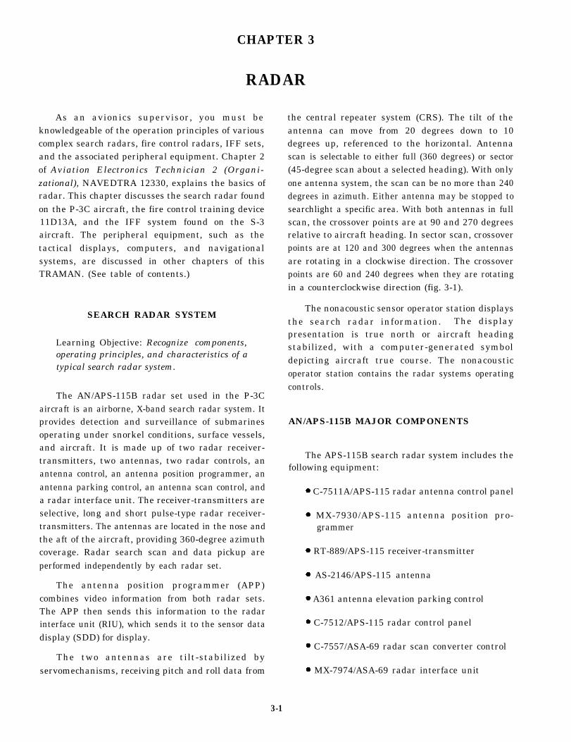
Fire Control (Manual Search)
Manual search allows the operator to stop theantenna from scanning and to direct it toward anydesired target detected during automatic search. Tiltor elevation control of the antenna, which wasprovided in automatic search, is still available inmanual search. In addition, control of the antenna inazimuth is now available. In the operation of anactual radar installation, control of the antenna in bothelevation and azimuth is a function of the hand
control. In the trainer, however, azimuth andelevation controls are separate. The provision ofseparate controls is of no great significance, exceptfor convenience of operation.
When manual search is initiated, the acquisitionmarks bracket the range sweep line (B-trace), andboth the B-trace and the acquisition marks movetogether in azimuth. The position of the acquisitionmarks in range is also available in the manual searchmode. This allows them to be positioned anywhereon the B-trace from zero to maximum range,depending on range selected. For example, if theradar is operating in the 0- to 10,000-yard range, anda target appears at 5,000 yards, the acquisition marksmay be moved to bracket the target by use of therange control.
The major display differences between automaticsearch and manual search are that the acquisition
Figure 3-12.-A. Antenna scan pattern. B. Antenna coverage pattern.
3-13
marks bracket and move with the B-trace, and theantenna is controllable in azimuth. All symbols thatwere present in automatic search, including theartificial horizon, are present in manual search. Thehorizon line still functions to indicate aircraft attitude.It should also be reasonable to expect to see no targetsother than the ones that appear on the range sweepline, since the antenna is no longer scanning.
Fire Control (Lock on)
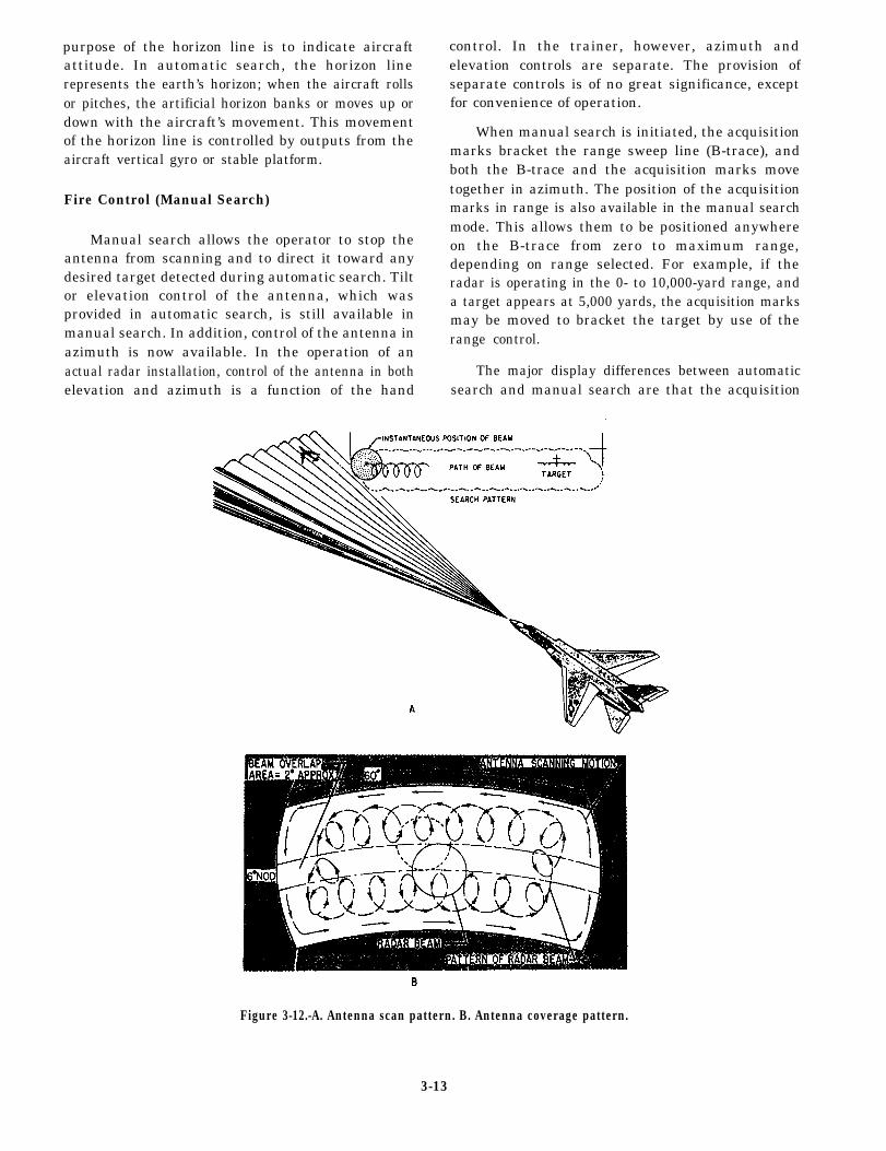
The lock on mode is a momentary mode ofoperation between manual track and automatic track.Some radars combine the previously describedmanual operations and lock on mode into one modecalled “acquisition.” The term acquisition, as used inoperation of a radar set, refers to a momentary modeof operation. The time period for acquisition beginsat the moment the operator depresses a control switchtransferring antenna control from automatic search tomanual search. During this period, the operator hascomplete control of antenna position, both in azimuthand elevation, and may also control a symbol on theindicator called an “acquisition symbol.” If theoperator places the acquisition symbol over theselected target, it causes coincidence between thetracking gate and the target in the range and trackingcircuits of the radar. Acquisition is complete whenlock on occurs, and the system switches to automatictrack. Lock on is accomplished by a change in theB-scope presentation and the blanking of the PPIscope. However, in the trainer, manual track may becontinued after leek on, if desired.
On the B-scope, the acquisition symbol isremoved and replaced with a range strobe or notchsuperimposed on the target, as shown in figure 3-13.The artificial horizon remains as before. Note thereare two symbols present now that were not previouslypresent. One of these is a small dot, called a steeringdot. The purpose of the steering dot is to indicateantenna position, which also presents target positionwith respect to the attacking aircraft. For a purepursuit course, the pilot need only maneuver theaircraft to cause the steering dot to remain in thecenter of the scope. When the steering dot is in thecenter of the scope on a pure pursuit course, the targetis dead ahead of the attacking aircraft.
The second symbol, which was not present in theprevious modes, is a circle. This circle is called a“range circle,” and its diameter is proportional torange. Normally, lock on occurs at near maximumrange, which produces a range circle of maximum
size. As the range between the attacking aircraft andthe target decreases, the diameter of the circle alsodecreases, keeping the operator informed of the rangeto the target. In addition to these symbols, two otherindications of range are presented at the time the radarlocks on. A light, known as the lock on or acquisitionlight, is illuminated when the target has been acquiredand lock on has been accomplished. Range is alsopresented in digital form in a small window similar tothe mileage counter of an automobile.
Fire Control (Automatic Track)
The automatic track submode of fire controlresults from the manual track mode upon release ofthe manual controls (range and azimuth). Remember,prior to automatic tracking, the antenna had beenmanually controlled in both elevation and azimuth,and the range strobe (notch) had been controlled bythe range control. To initiate automatic tracking, theoperator releases the manual controls, and the radarswitches to automatic track. At this time, the antennais caused to track the target by the antenna servosystem error circuits.
Range tracking is accomplished in the rangetracking circuits. Automatic tracking continues untilone of three things occurs. First, lock on will be lostif the attacking aircraft is closing on the target at a rategreater than 700 knots, or if an opening rate greaterthan 200 knots should occur. Second, the target willbe lost, and the radar will unlock if the target does notremain within the tracking window (antenna limits inazimuth and elevation). Finally, the target will be lostif the range exceeds maximum tracking range.
Figure 3-13.-B-scan presentation after lock on.
3-14
Maximum range for tracking is 40,000 yards. Atranges beyond 40,000 yards, the return echo will betoo weak to maintain lock on. If unlock occurs, thesystem is automatically returned to automatic search,and the cycle of manual track and acquisition must berepeated to regain target tracking.
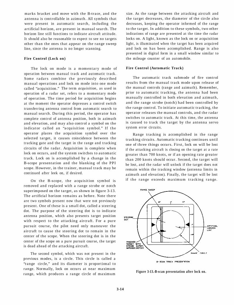
Fire Control (Breakaway)
The final submode of fire control is known asbreakaway. This mode occurs automatically if thetarget is tracked to a range that would endanger theattacking aircraft. During automatic track of a targetthat has a decreasing range (attacking aircraft isclosing on the target), the range circle is removed atthe time the range to the target gets to 3,500 yards. Inits place, a large X is displayed, which indicates timeto breakaway from the attack (fig. 3-14). Also at thistime, the steering dot will move to a position on thescope to indicate the safe direction for the attackingaircraft to turn to execute a safe breakaway. In theillustration, minimum range has been reached and thebreakaway X has appeared. The steering dot ispresently positioned to the right and above center.
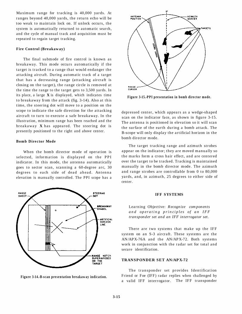
Bomb Director Mode
When the bomb director mode of operation isselected, information is displayed on the PPIindicator. In this mode, the antenna automaticallygoes to sector scan, scanning a 60-degree arc, 30degrees to each side of dead ahead. Antennaelevation is manually controlled. The PPI scope has a
Figure 3-14.-B-scan presentation breakaway indication.
Figure 3-15.-PPI presentation in bomb director mode.
depressed center, which appears as a wedge-shapedscan on the indicator face, as shown in figure 3-15.The antenna is positioned in elevation so it will scanthe surface of the earth during a bomb attack. TheB-scope will only display the artificial horizon in thebomb director mode.
The target tracking range and azimuth strobesappear on the indicator; they are moved manually sothe marks form a cross hair effect, and are centeredover the target to be tracked. Tracking is maintainedmanually in the bomb director mode. The azimuthand range strobes are controllable from 0 to 80,000yards, and, in azimuth, 25 degrees to either side ofcenter.
IFF SYSTEMS
Learning Objective: Recognize componentsand operating principles of an IFFtransponder set and an IFF interrogator set.
There are two systems that make up the IFFsystem on an S-3 aircraft. These systems are theAN/APX-76A and the AN/APX-72. Both systemswork in conjunction with the radar set for total andsecure identification.
TRANSPONDER SET AN/APX-72
The transponder set provides IdentificationFriend or Foe (IFF) radar replies when challenged bya valid IFF interrogator. The IFF transponder
3-15

Figure 3-16.-SA-176/A RF transmission line switch.
processes valid IFF interrogations and provides codedpulse train replies to give automatic radaridentification of the aircraft in one of five modes. Thefive modes are discussed later in this chapter.
The transponder set also provides the SelectiveIdentification Feature (SIF) to permit a specificaircraft to be selected from other properly respondingaircraft.
Major Components
The transponder set consists of four main boxesand a test set. These components will be discussed inthe following text.
RF TRANSMISSION LINE SWITCHSA-1769/A.— The RF transmission switch (fig. 3-16)alternately connects the transponder set to the top orbottom UHF L-band antenna. This switching (lobing)
Figure 3-17.-C-6280(P)/APX transponder control box.
operates at 38 Hz. The lobing action prevents theantenna system from being blanked out during aircraftmaneuvers.
TRANSPONDER SET CONTROL C-6280(P)/APX.— The IFF control box (fig. 3-17) provides theIFF transponder operational and test controls. TheIFF transponder control box controls the transponderin any of the five modes: modes 1, 2, 3A, C, and 4.
RECEIVER-TRANSMITTER RT-859/APX-72.— The receiver-transmitter (fig. 3-18) will
Figure 3-18.-RT-859/APX-72 receiver-transmitter.
3-16

transmit a reply when RF interrogation is receivedfrom an IFF interrogator. If the interrogation is valid,a coded reply is transmitted. This reply is received bythe interrogator and processed for display for aircraftidentification and location. The transponder iscapable of operating in five modes and superimposingfour special signals on the mode replies.
COMPUTER KIT-1A/TSEC.— This computerallows the IFF transponder to respond to mode 4interrogations. Mode 4 is a secure mode of operation.
TRANSPONDER TEST SET TS-1843/APX.— The test set (fig. 3-19) generates properlycoded test signals for the desired mode. Theseinterrogation signals are then applied to thetransponder. The test set then checks the replies forfrequency, bracket-pulse spacing, power, and antennastanding-wave ratio. The resulting IFF system checkwill provide a GO/NO-GO indication on the IFFtransponder control box.
Transponder Set Functional Description
The IFF transponder control box allows anautomatic IFF capability when the aircraft isinterrogated by a valid interrogation. Special modesand codes can be manually set on the IFF control box,receiver-transmitter, and on the computer. Thecontrol box also initiates the self-test function throughthe test set.
RECEIVED SIGNALS.— The interrogator-transmitted signals are received by the aircraftthrough the UHF L-band blade antennas. Thesesignals are on a frequency of 1030 MHz. Thereceiver-transmitter recognizes the signals throughpulsewidth and spacing detection. Modes 1, 2, 3/A,C, and TEST use two interrogation pulses and oneside-lobe suppression pulse that are 0.8 (±0.1)microsecond wide. Pulse spacings between the twointerrogation pulses are slightly different, dependingon the mode. These spacings are as follows:
Mode 1: 3.0 (±0.2) microseconds
Mode 2: 5.0 (±0.2) microseconds
Mode 3/A: 8.0 (±0.2) microseconds
Mode C: 21.0 (±0.2) microseconds
TEST: 6.5 (±0.2) microseconds
Figure 3-19.-TS-1843/APX test set.
IFF TRANSPONDER RECOGNITION.—Recognition of the interrogation mode is done bypassing the first interrogation pulse through atime-delay circuit and matching this first pulse withthe second pulse position. The delays are of 3, 5, 8,or 21 microseconds. Mode 4 capability is providedwhen the computer is operating in the system. Mode4 interrogation pulse characteristics consist of fourpulses 0.5 (±0.15) microsecond wide, referencedfrom the leading edge of the first pulse in multiples of2 microseconds. The 4 pulses maybe followed by asmany as 33 additional pulses spaced as close as 2microseconds. The side lobe suppression pulse isplaced 2 (±0.15) microseconds from the leading edgeof the fourth pulse.
SIDE-LOBE SUPPRESSION.— The side-lobesuppression pulse allows the transponder to accept themain lobe and to reject minor lobe signals from theinterrogation stations. This ensures correct operationof the system.
3-17
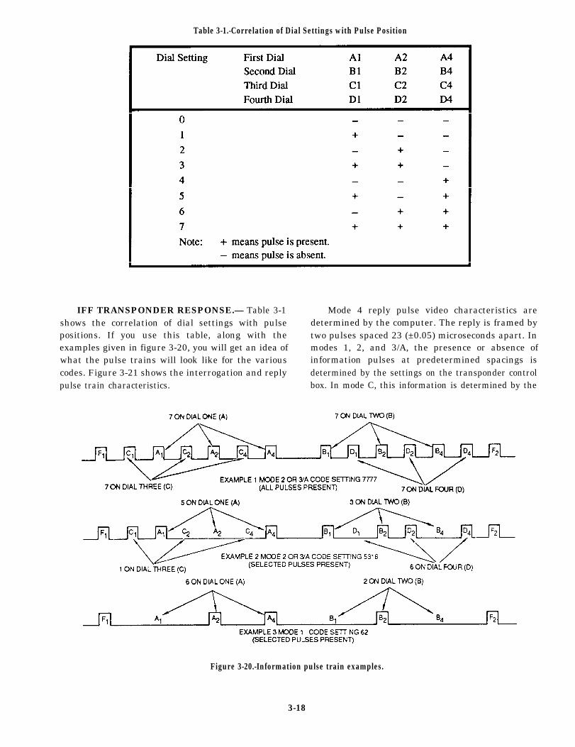
Table 3-1.-Correlation of Dial Settings with Pulse Position
IFF TRANSPONDER RESPONSE.— Table 3-1 Mode 4 reply pulse video characteristics areshows the correlation of dial settings with pulse determined by the computer. The reply is framed bypositions. If you use this table, along with the two pulses spaced 23 (±0.05) microseconds apart. Inexamples given in figure 3-20, you will get an idea of modes 1, 2, and 3/A, the presence or absence ofwhat the pulse trains will look like for the various information pulses at predetermined spacings iscodes. Figure 3-21 shows the interrogation and reply determined by the settings on the transponder controlpulse train characteristics. box. In mode C, this information is determined by the
Figure 3-20.-Information pulse train examples.
3-18

airspeed-altitude computer. All framing andinformation reply pulses are 0.45 (±0.1) microsecondwide. All modes are transmitted by the RT at afrequency of 1090 MHz.
Mode 1.— The reply pulse train consists of fromzero to five information pulses framed by two framingpukes. The spacing between the information pulses isin multiples of 2.9 (±0.05) microseconds from theinitial framing pulse. The position where the sixthinformation pulse would be (17.4 [±0.05] micro-seconds from the initial framing pulse) is not used.There are 32 different codes available for use from thespecified five information pulses.
Mode 2 and 3/A.— When transmitted, these replytrains contain from zero to 12 information pulses, plusthe two framing pulses. The information pulsespacing is in multiples of 1.45 (±0.05) microsecondsfrom the initial framing pulse. The position where theseventh information pulse would be (10.5 [±0.05]microseconds from the initial framing pulse) isnormally not used. There are a possible 4,096different codes available from the specified 12information pulses.
Mode C.— When the Airspeed-Altitude Com-puter is connected in the system, the reply trainconsists of from 1 to 11 information pulses and 2framing pulses. The information pulses are spaced inmultiples of 1.45 (±0.05) microseconds from theinitial framing pulses. The positions where theseventh and the ninth pulses are normally located(10.5 [±0.05] and 13.05 [±0.05] microseconds fromthe initial framing pulse) are not used. When there isa pulse in the thirteenth position (18.85 [±0.05]microseconds from the initial framing pulse), there is
a special position indicator pulse also generated in thetrain. This pulse is located 24.65 (±0.05) micro-seconds from the initial framing pulse. There is atotal of 2,048 possible codes available from thespecified 11 information pulses. When theairspeed-altitude computer is not on-line, the replytrain will be the framing pulses only.
Mode 4.— This reply train is determined by theKIT-1A/TSEC.
IDENT Function.— The identification-of-position (IDENT) function is used in modes 1, 2, and3/A. The IDENT function, which can be selected bythe pilot for transmission for approximately20-second intervals, is used to distinguish betweenaircraft displaying the same coding. When used inmode 1, the reply pulse train containing the code inuse is transmitted twice for each trigger puke received.The second train is 24.65 (±0.05) microseconds fromthe leading edge of the first framing pulse of the firstreply train. The IDENT function in modes 2 and 3/Auses the special position indicator (SPI) pulse. The replypulse train containing the code in use is followed by apulse for each trigger received. This SPI pulse is 24.65(±0.05) microseconds from the leading edge of the firstframing pulse of the reply train.
Emergency Function.— The EMERGENCYsignals are selected by the pilot to indicate an in-flightemergency. The emergency function is used withmodes 1, 2, and 3/A. For modes 1 and 2, the replypulse train containing the code in use is transmittedonce for each trigger pulse received, followed bythree sets of framing pulse pairs with no informationpukes. The three sets of framing pulses are located24.65 (±0.1), 44.95 (±0.15), 49.30 (±0.20), 69.60
Figure 3-21.-Normal reply pulse characteristics.
3-19

(±0.25), 73.95 (±0.30), and 94.25 (±0.35) micro-seconds from the leading edge of the initial framingpulse. In mode 3/A, one reply pulse train containingthe code 7700 is transmitted, followed by the threesets of framing pulse pairs with no informationpulses. The location of these framing pulse pairs isthe same as in modes 1 and 2.
Special Position Indicator.— The specialposition indicator (SPI) allows the air trafficcontroller to differentiate aircraft above or below agiven altitude. This puke is present in the reply pulsetrain in mode C when a D4 pulse (18.85 [±0.05]microseconds from the initial framing pulse) is used.The SPI pulse is located 24.65 (±0.01) microsecondsfrom the initial framing pulse. This pulse issometimes called the mode C caboose pulse. ThisSPI pulse is the initial framing pulse for the secondreply pulse train. The SPI pulse is the same pulseused in the mode 2 and 3/A IDENT function.
X-Pulse Function.— Special aircraft, such asdrones, are identified by the transmission of theX-pulse. This pulse (10.15 [±0.05] microsecondsfrom the initial framing pulse) appears in a normallyunused position. This pulse is generated when theIFF transponder control box is modified by groundinga single external control lead. With this modification,all replies in modes 1, 2, and 3/A will include thispulse, along with the normal framing and informationpulses.
SELF-TEST MODE.— When the TEST switcheson the IFF transponder control box are enabled, aninterrogation pulse pair is applied from the test set tothe receiver-transmitter. Upon receiving theseinterrogation pulses, the RT replies to the test set. Thetest set then analyzes the replies for bracket-spacingfrequency, power, and antenna circuit VSWR. Thetest set will give a GO/NO-GO indication on thecontrol box. There is a switch for each of the modes1,2, 3/A, and C.
MONITOR OPERATION.— When the RADTEST-OUT-MON switch on the IFF transpondercontrol box is set to the MON position, thetransponder performance is checked. The test set willmonitor the performance by detecting the repliesgenerated in response to external interrogationsignals. If a GO condition is detected, the TESTindicator on the transponder control box willilluminate. For a NO-GO condition, the TESTindicator remains off.
INTERROGATOR SET AFUAPX-76A(V)
The interrogator set is used in conjunction withthe aircraft’s radar set. It provides air-to-air modes 1,2, 3/A, 4, SIF, and IFF mode 4 challenges. The IFFinterrogator receives a basic trigger from the radar set,and a delayed radar trigger is returned to the radarafter generation of the IFF interrogator trigger. TheIFF replies are decoded and combined with thedisplayed radar return video. The interrogator setuses receiver side-lobe suppression (RSLS) andinterrogator side-lobe suppression (ISLS). The videooutput is developed in the IFF interrogator, and isapplied to the radar set for display.
Interrogator Set Major Components
The interrogator set consists of six majorcomponents. These six are discussed in the followingtext.
ANTENNA AS-2719/AP.— The interrogator setuses an antenna that is hard mounted to the radar setantenna The IFF portion of the antenna is imbeddedin the upper part of the antenna dish, and consists of10 IFF elements.
INTERROGATOR SET CONTROL C-7383/APX-76A(V).— The interrogator control box(fig. 3-22) provides operating mode selection of theSIF, or mode 4 code. The control box contains fivethumbwheel switches to select the desiredinterrogation mode, or standby, and the desired code.A momentary two-pos i t ion togg le switch(TEST/CHAL CC) allows for loop-testing the IFF, orto provide correct code challenge. The loop-testingallows for the interrogation of the onboardtransponder set (AN/APX-72) by the IFF interrogator.Correct code challenge enables interrogations forwhich IFF display pulses are generated if the received
Figure 3-22.-C-7383/APX-76A(V) interrogator control box.
3-20

SIF reply code is identical to the code switch settings.There are two indicators (FAULT and CHAL) thatindicate correct operating status of the system. Themode 4 alarm may be overridden by using the toggleswitch M4 ALARM OVERRIDE.
RECEIVER-TRANSMITTER RT-868A/APX-76A(V).— The receiver-transmitter (fig. 3-23)takes the mode 1,2, 3/A, or 4 interrogation and ISLSpulses and modulates a 1030 MHz carrier wave withthem. This is the transmitted signal from theinterrogator set. The transponder reply signal, at thereply frequency of 1090 MHz, is amplified, detected,and processed by the receiver section. The replyvideo is then sent to the radar set for display on thevarious indicators.
There are three fault flags on the front of the RTthat indicate malfunctions in one of the threefunctional sections of the receiver-transmitter.
SWITCH-AMPLIFIER SA-1568A/APX-76A(V).— The switch-amplifier (fig. 3-24) switches theinterrogator’s RF output from the sum antennachannel to the difference antenna channel for theduration of the ISLS pulse. During this time, theoutput is amplified by 4 to 7 dB. This amplificationprovides the required antenna output characteristics.
ELECTRONIC SYNCHRONIZER SN-416A/APX-76A(V).— The synchronizer (fig. 3-25)generates the initiation and interrogation cycles. Thesynchronizer provides a functional link between the
Figure 3-23.-RT-868A/APX-76A(V) receiver-transmitter.
Figure 3-24.-SA-1568A/APX-76A(V) switch-amplifier.
radar trigger generation and the radar modulationcircuits.
COMPUTER KIR-1A/TSEC.— This computeris used for mode 4 security and decoding for secureoperation.
Interrogator Functional Description
The IFF interrogator challenges and identifiesproperly equipped targets on the display groups. Itchallenges in modes 1, 2, 3/A, SIF, or mode 4. Targetresponses are shown on the display group next to thetarget in the form of numbered cues.
MODES 1, 2, AND 3/A TRANSMISSION.—When the TEST-CHAL CC switch on the interrogatorcontrol box is set to the CHAL CC position, theinterrogation cycle is initiated and lasts for 5 to 10seconds. The basic radar trigger is applied to the
Figure 3-25.-SN-416A/APX-76A(V) synchronizer.
3-21

synchronizer, and a delayed radar trigger is sent backto the radar set after the interrogation trigger isgenerated. The synchronizer develops three basicsignals:
. The interrogator trigger which, via thereceiver-transmitter modulating circuit, modulates thetransmission. The interrogation trigger consists ofthree pulses. P1 and P3 are interrogation pulsesspaced either 3, 5, or 8 microseconds apart. In mode1, the spacing is 3 microseconds, mode 2 has a5-microsecond space, and mode 3/A has an8-microsecond space. The ISLS pulse (P2) is always2 microseconds after the P1 pulse.
. The gain time control (GTC) trigger, whichinitiates the receiver gate and the GTC circuits in thereceiver-transmitter.
. The ISLS control gate, which controlsswitching of the antenna pattern for ISLS purposes.
The ISLS control gate, which precedes the P2ISLS pulse by about 0.6 microsecond, is applied tothe switch amplifier. When triggered by theinterrogation trigger, the receiver-transmittergenerates RF pulses at the transmitting frequency of1030 MHz at a nominal peak power level of 2 kW.These pulses are applied to the sum channel of theswitch-amplifier. The difference channel pathbetween the receiver-transmitter and theswitch-amplifier is not used during transmission.When the ISLS control gate is not present at theswitch-amplifier, the RF pulses from the RT sumchannel are passed straight to the antenna via the sumchannel line for radiation out of the sum antennapattern. This pattern is a main lobe with its axis alongthe antenna’s boresight, and small side lobes on eitherside of the boresight. The P1 and P3 interrogationpulses are radiated in the sum pattern.
W h e n t h e I S L S g a t e a r r i v e s a t t h eswitch-amplifier, shortly before the P2 pulse, the sumchannel input at the switch-amplifier is switched tothe difference channel coax to the antenna. Theswitch-amplifier amplifies the P2 ISLS pulse to anominal peak power of 8 kW prior to its being sent tothe antenna. This pulse is transmitted through thedifference antenna pattern, which is two main lobeswith their axes about 20 degrees on either side of theantenna’s boresight, with a minimum signal strengthalong the boresight.
The reason for the two radiation patterns is tonarrow the antenna beamwidth effectively in
conjunction with the operation of the ISLS circuit atthe transponder. The IFF transponder responds onlyto the P1 and P3 interrogation pukes, which are atleast 9 dB above the P2 pulse. The transponder willnot respond if the P2 pulse level exceeds the P1 level.If an IFF transponder is located more than a smallangle off of the antenna’s boresight, the P2 pulse willbe received at a much higher level than the P1 and P3pulses, and no reply will be generated.
MODE 4 TRANSMISSION.— Mode 4 opera-tion is very similar to that of modes 1,2, and 3/A. Themajor difference is that the KIR-1A computergenerates the interrogation trigger, GTC trigger, andthe ISLS control gate instead of the synchronizer.The synchronizer generates a mode 4 pretrigger that issent to the computer. The computer then prepares thechallenge video, which is sent back to thesynchronizer for entry onto the interrogator triggerline to the RT. Mode 4 transmission is the same as inthe other modes as far as the patterns are concerned.Both the sum antenna pattern and the differenceantenna pattern are used.
RECEPTION.— During reception, both the sumand difference antenna patterns are open for IFFtransponder reply energy. The purpose of this is toeffectively narrow the reply reception antennabandwidth. This function is called RSLS. The replyRF energy is applied to the receiver-transmitter viathe switch-amplifier’s sum and difference channels.If the energy is above maximum receiver sensitivity,and the sum channel energy is greater than thedifference channel energy by a fixed factor, thereceiver will develop video pulses for decoding.
These video pulses are applied to the mode 4decoding circuits within the receiver-transmitter andto modes 1, 2, and 3/A decoding circuits in thesynchronizer. For modes 1, 2, and 3/A, the videopulses are checked for the presence of the standardIFF reply bracket pulses spaced 20.3 microsecondsapart. If these pulses are there, a single video pulse isapplied to the radar set for display. The coded pulsesbetween the brackets are checked against the codeselected at the IFF interrogator control. If the codesmatch, another single display video pulse is applied tothe radar set for display. This second pulse is delayed12 microseconds (or 28 microseconds if thelong-range display is enabled) from the first pulse.When the correct code challenge is used to initiate theinterrogation, the first pulse (bracket decode) is notsent to be displayed.
3-22
In mode 4, the reply video pulse is checked by theRT for proper pulse spacing and width. A single replypulse is forwarded to the computer for furtherdecoding. The mode 4 decoded video is applied to thesynchronizer, where two pulses spaced 12 or 28microseconds apart are generated for display by theradar set.
PERFORMANCE MONITORING.— The IFFinterrogator set includes performance monitoringcircuits in each of the boxes. When a fault is detected,a signal is sent through the synchronizer to the controlbox. This signal will cause a FAULT light toilluminate instead of the normal CHAL light.
When the TEST-CHAL CC switch is set to TEST,the IFF interrogator and the IFF transponder arelinked together. This is done by disabling the normalsuppression, ISLS, and RSLS operations. The triggertiming is also modified to place the zero-range repliesat approximately 4 nautical miles on the radar display.In this configuration, the two sets are checked by eachother for proper performance.
REVIEW QUESTIONS
Q1. What type of search radar is the APS-115B?
Q2. What is the tilt range of the AS-2146/APS-115?
Q3.
Q4.
Q5.
Q6.
Q7.
Q8.
Q9.
Q10.
Q11.
Q12.
Q13.
Q14.
Which control switch on the C-7511A/APS-115 is used to select the antenna sectormode?
How many functional subsections are in aRT-889/APS-115?
What is the scan rate of the AS-2146/APS-115in the long pulse mode of operation?
How many operating modes are available onthe 11D13A?
What is the minimum range in fire controloperations?
In the fire control (automatic search) mode,what name is given to the 1/4-inch scan line?
At what closing rate will lock on be lost in thefire control (automatic track) mode?
What indication on the scope indicatesbreakaway?
What are the five modes used in IFF opera-tions?
What antenna(s) is/are used by the IFFtransponder system?
The APX-76 interrogator uses what carrierfrequency for transmission?
What light illuminates when one of theAPX-76 components fail?
3-23
