reliability, availability and serviceability (ras
TRANSCRIPT
Reliability, Availability and
Serviceability (RAS) Integration
and Validation Guide for the
Intel® Xeon® Processor E7- v3
Family
Error Reporting through EMCA Gen 2
April 2015
2
Notice: This document contains information on products in the design phase of development. The information here is subject to
change without notice. Do not finalize a design with this information.
You may not use or facilitate the use of this document in connection with any infringement or other legal analysis concerning Intel
products described herein. You agree to grant Intel a non-exclusive, royalty-free license to any patent claim thereafter drafted
which includes subject matter disclosed herein.
No license (express or implied, by estoppel or otherwise) to any intellectual property rights is granted by this document.
The products described may contain design defects or errors known as errata which may cause the product to deviate from
published specifications. Current characterized errata are available on request.
This document contains information on products, services and/or processes in development. All information provided here is subject
to change without notice. Contact your Intel representative to obtain the latest Intel product specifications and roadmaps.
Intel disclaims all express and implied warranties, including without limitation, the implied warranties of merchantability, fitness for a particular purpose, and non-infringement, as well as any warranty arising from course of performance, course of dealing, or
usage in trade.
Tests document performance of components on a particular test, in specific systems. Differences in hardware, software, or
configuration will affect actual performance. Consult other sources of information to evaluate performance as you consider your
purchase. For more complete information about performance and benchmark results, visit http://www.intel.com/performance.
Intel does not control or audit third-party benchmark data or the web sites referenced in this document. You should visit the
referenced web site and confirm whether referenced data are accurate.
Copies of documents which have an order number and are referenced in this document may be obtained by calling 1-800-548-4725
or by visiting www.intel.com/design/literature.htm.
Intel, the Intel logo, and Intel Xeon are trademarks of Intel Corporation in the U.S. and/or other countries.
*Other names and brands may be claimed as the property of others.
Copyright © 2015, Intel Corporation. All Rights Reserved.
3
Contents 1 Introduction ........................................................................................................................ 5
1.1 References ..................................................................................... 6
1.2 Definition of Terms .......................................................................... 7
2 Enhanced MCA Gen2 Overview ................................................................................... 8
3 System Configuration.................................................................................................... 13
4 Software Integration..................................................................................................... 14
4.1 Feature Setup Flow........................................................................ 15
4.2 SMM Error Handling Process with MCE Handler.................................. 16
4.3 Enhanced MCA Error Log Data Structure .......................................... 17
5 Intel® DFx Validation Recipes .................................................................................. 23
5.1 BIOS Setup .................................................................................. 23
5.2 The Process to EMCA L1 Directory Address ....................................... 25
5.3 Intel® DFx Validation Flow ............................................................. 26
6 Linux*--Based Validation Recipes ........................................................................... 28
6.1 Persistent Memory Correctable Error Validation Recipe ....................... 28
6.2 Persistent Memory Uncorrectable Non Fatal Error Validation Recipe ..... 29
Figures
Figure 2-1. EMCA1 and EMCA2 Corrected Error Signaling Flow Comparison ....................... 9
Figure 2-2. EMCA1 and EMCA2 Uncorrected Error Signaling Flow Comparison .................. 10
Figure 4-1. Firmware First Model EMCA2 Error Handling ................................................ 14
Figure 4-2. EMCA2 High Level Flow............................................................................. 16
Figure 4-3. Enhanced MCA Log Processing Flow ........................................................... 17
Figure 4-4. EMCA Error Log Data Structure .................................................................. 18
Figure 4-5. EMCA L1 Directory Data Structure ............................................................. 19
Figure 5-1. “System Event Log” Menu Setup ................................................................ 24
Figure 5-2. “WHEA Settings” Menu Setup .................................................................... 24
Figure 5-3. EMCA L1 Directory Address Shown in BIOS Serial Log .................................. 25
Tables
Table 1-1. EMCA2 Definition, Business Value, and User Experience ................................... 5
Table 1-2. EMCA2 Support Platform Scope .................................................................... 6
Table 1-3. Definitions ................................................................................................. 7
Table 2-1. CE Handling: Legacy MCA Mode, EMCA Gen1, and Gen2 ................................ 11
4
Table 2-2. UCE Handling: Legacy MCA Mode, EMCA Gen1, and Gen2 .............................. 12
Table 3-1. Minimum System Configuration .................................................................. 13
Table 4-1. ELOG Entry Pointer (APIC ID, Elog Entry) ..................................................... 19
Table 4-2. The Index Description of Enhanced MCA Logging DSM ................................... 20
Table 4-3. Enhanced MCA L1 Directory Format ............................................................. 21
Table 4-4. ACPI Generic Error Status Block Field .......................................................... 22
5
1 Introduction
The document describes the software and hardware integration and validation
methodologies associated with Enhanced Machine Check Architecture Gen 2
(EMCA2) RAS features into Intel® Xeon® Processor E7 – 8800/4800/2800 v3
based systems (code named Haswell EX). For those who are responsible for
BIOS development, system and platform validation, or product marketing, this
document provides knowledge about how to integrate software and hardware
to make the feature functioning with adequate validation methodologies.
Comparing to Legacy MCA Mode and EMCA1, EMCA2 feature provides
additional capabilities for BIOS/FW to take first line error handling role by
identifying error and collecting richer error logs in addition to existing hardware
and OS/VMM level error handling. Refer to Table 3-1 and Table 3-2 for more
details about the comparisons. This firmware first model makes system
software get enhance error information to proceed error recovery before
system goes to shut down process.
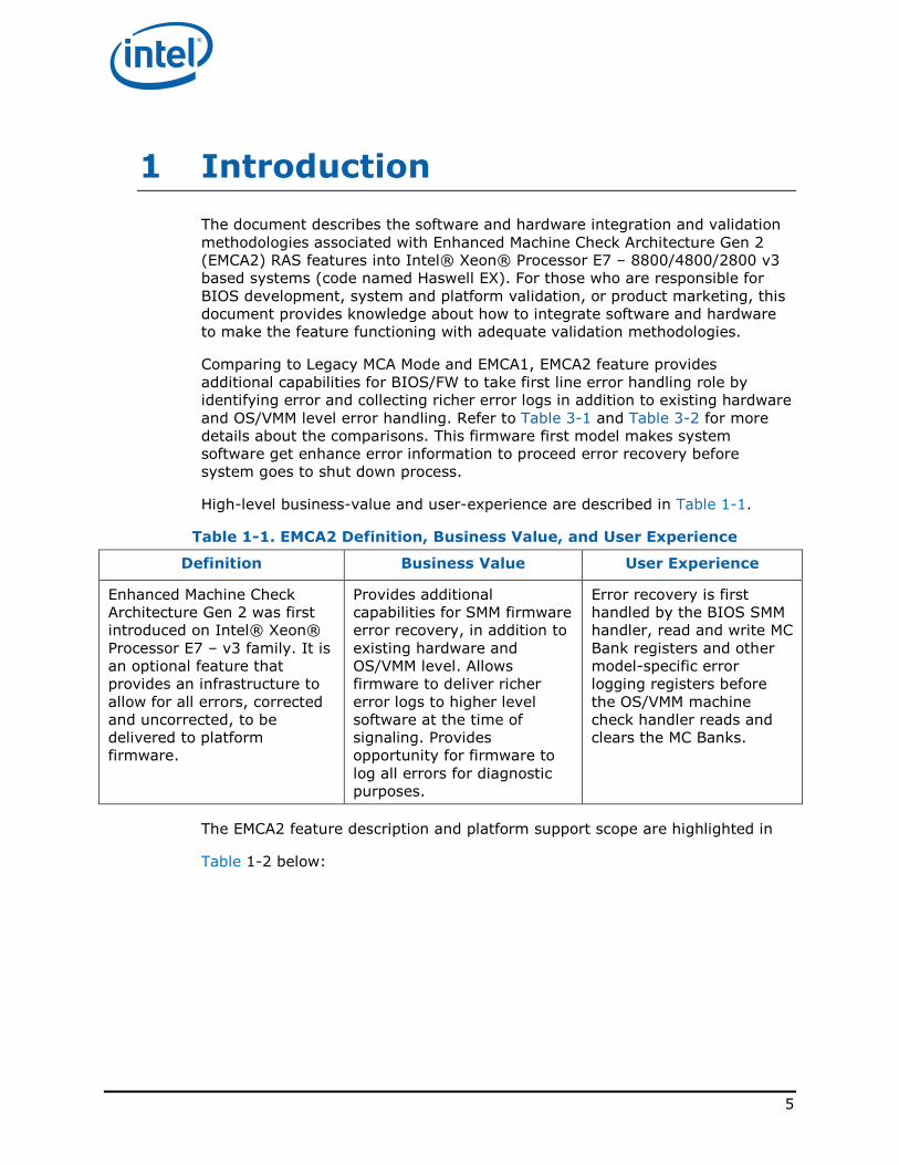
High-level business-value and user-experience are described in Table 1-1.
Table 1-1. EMCA2 Definition, Business Value, and User Experience
Definition Business Value User Experience
Enhanced Machine Check
Architecture Gen 2 was first
introduced on Intel® Xeon®
Processor E7 – v3 family. It is
an optional feature that
provides an infrastructure to
allow for all errors, corrected
and uncorrected, to be
delivered to platform
firmware.
Provides additional
capabilities for SMM firmware
error recovery, in addition to
existing hardware and
OS/VMM level. Allows
firmware to deliver richer
error logs to higher level
software at the time of
signaling. Provides
opportunity for firmware to
log all errors for diagnostic
purposes.
Error recovery is first
handled by the BIOS SMM
handler, read and write MC
Bank registers and other
model-specific error
logging registers before
the OS/VMM machine
check handler reads and
clears the MC Banks.
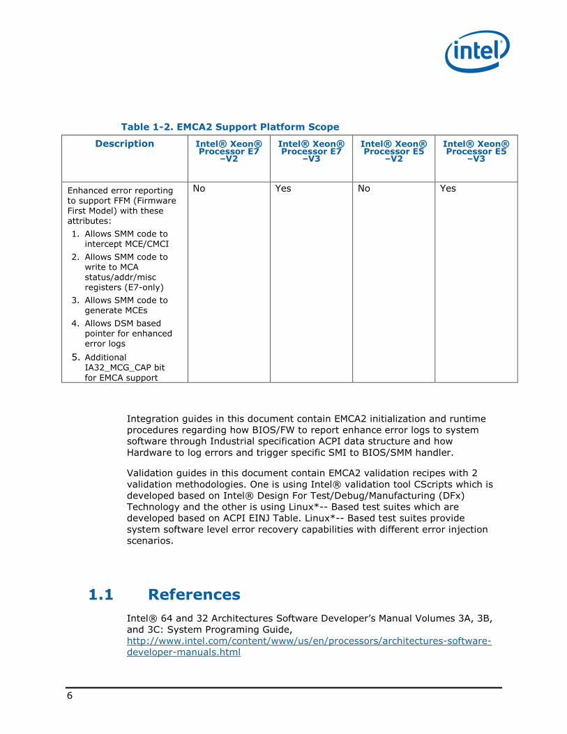
The EMCA2 feature description and platform support scope are highlighted in
Table 1-2 below:
6
Table 1-2. EMCA2 Support Platform Scope
Description Intel® Xeon® Processor E7
–V2
Intel® Xeon® Processor E7
–V3
Intel® Xeon® Processor E5
–V2
Intel® Xeon® Processor E5
–V3
Enhanced error reporting
to support FFM (Firmware
First Model) with these
attributes:
1. Allows SMM code to
intercept MCE/CMCI
2. Allows SMM code to
write to MCA
status/addr/misc
registers (E7-only)
3. Allows SMM code to
generate MCEs
4. Allows DSM based
pointer for enhanced
error logs
5. Additional
IA32_MCG_CAP bit
for EMCA support
No Yes No Yes
Integration guides in this document contain EMCA2 initialization and runtime
procedures regarding how BIOS/FW to report enhance error logs to system
software through Industrial specification ACPI data structure and how
Hardware to log errors and trigger specific SMI to BIOS/SMM handler.
Validation guides in this document contain EMCA2 validation recipes with 2
validation methodologies. One is using Intel® validation tool CScripts which is
developed based on Intel® Design For Test/Debug/Manufacturing (DFx)
Technology and the other is using Linux*-- Based test suites which are
developed based on ACPI EINJ Table. Linux*-- Based test suites provide
system software level error recovery capabilities with different error injection
scenarios.
1.1 References
Intel® 64 and 32 Architectures Software Developer’s Manual Volumes 3A, 3B,
and 3C: System Programing Guide,
http://www.intel.com/content/www/us/en/processors/architectures-software-
developer-manuals.html
7
ACPI 5.1 Specification, www.acpi.info
UEFI Specification 2.4, www.uefi.org
1.2 Definition of Terms
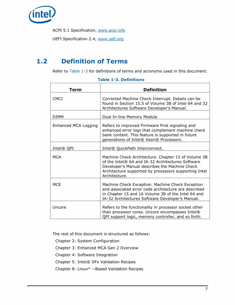
Refer to Table 1-3 for definitions of terms and acronyms used in this document.
Table 1-3. Definitions
Term Definition
CMCI Corrected Machine Check Interrupt. Details can be
found in Section 15.5 of Volume 3B of Intel 64 and 32
Architectures Software Developer’s Manual.
DIMM Dual In-line Memory Module
Enhanced MCA Logging Refers to improved Firmware First signaling and
enhanced error logs that complement machine check
bank content. This feature is supported in future
generations of Intel® Xeon® Processors.
Intel® QPI Intel® QuickPath Interconnect.
MCA Machine Check Architecture. Chapter 15 of Volume 3B
of the Intel® 64 and IA-32 Architectures Software
Developer’s Manual describes the Machine Check
Architecture supported by processors supporting Intel
Architecture.
MCE Machine Check Exception. Machine Check Exception
and associated error code architecture are described
in Chapter 15 and 16 Volume 3B of the Intel 64 and
IA-32 Architectures Software Developer’s Manual.
Uncore Refers to the functionality in processor socket other
than processor cores. Uncore encompasses Intel®
QPI support logic, memory controller, and so forth.
The rest of this document is structured as follows:
Chapter 2: System Configuration
Chapter 3: Enhanced MCA Gen 2 Overview
Chapter 4: Software Integration
Chapter 5: Intel® DFx Validation Recipes
Chapter 8: Linux* --Based Validation Recipes
8
2 Enhanced MCA Gen2 Overview
Enhanced Machine Check Architecture Gen 2 (EMCA2) is introduced in Intel®
Xeon® Processor E7 – v3. It is the RAS feature that redirects Machine Check
Exceptions (MCE) and Corrected Machine Check Interrupts (CMCI) to firmware
first (via SMI) before sending it to the OS error handler. Enhanced MCA enables
BIOS-based recovery from errors. With EMCA2 enabled, BIOS is able to
configure each machine check bank to assert SMI instead of MCE or CMCI.
Before a MCE or CMCI is signaled, the specific SMI will be triggered and the
BIOS SMM handler is allowed to correct the error when possible. On Intel®
Xeon Processor E7 – v3 processors, the BIOS SMM handler is also allowed to
access data in every MC bank IA32_MCi_STATUS, IA32_MCi_ADDR and
IA32_MCi_MISC.
Prior to enhanced machine check architecture (EMCA), IA32-legacy version of
Machine Check Architecture (MCA) implemented error handling where all the
errors were logged in architected registers (MC banks) and signaled to
OS/VMM. The legacy version had limited platform firmware capability for fault
diagnosis and Field Replaceable Unit (FRU) isolation e.g. DIMM, PCI Express*
device. Legacy MCA feature also had the following OS-based error handling
constraints:
1. Uncorrected errors (UCE) would require routing to NMI, the NMI handler
may lose fault containment.
2. NMI precludes error recovery. In some cases, MCE may be recoverable.
3. UCNA error reporting via SCI may not be fast enough. If “MCA Error
Control” (Cloaking) is enabled, then the signaling can leverage CMCI.
4. Some error logs are blocked in the BIOS/Firmware level access which
constrains the OS-based error handling capability. For example, some error
logs or registers are recorded in CSR or MSR shadow registers that may not
be fully accessed by OS/VMM level.
Due to the shortcomings of legacy MCA error handling, EMCA1 was developed
to allow firmware first to handle, collect, and build enhanced error logs then
report to system software. This way, system software is able to obtain richer
error logs for further error recovery decision. Once EMCA1 associate registers
and signaling plans are set, BIOS SMM handler collects MC Bank registers and
other model-specific error logging registers. For corrected error, SMI signals to
BIOS/SMM handler for first line error handling prior to CMCI signaling to
system OS. For uncorrected error, SMI and MCERR are triggered in the
meantime.
EMCA2 provides even more enhancement on firmware first model in error
handling including Enhanced SMM. Enhanced SMM provides new capabilities
such as Directed SMI, in-silicon SMM state save, extended SMM memory range
register (SMRR2), and SMM security. With EMCA2, SMM handler also extends
the capability by reading and writing to machine check banks instead of read
9
only in EMCA1. For uncorrected errors, MSMI is triggered first then MCERR
after SMM handler is exited.
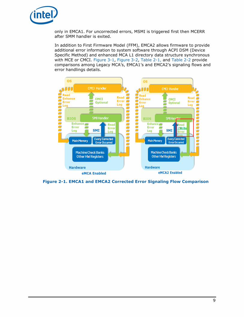
In addition to First Firmware Model (FFM), EMCA2 allows firmware to provide
additional error information to system software through ACPI DSM (Device
Specific Method) and enhanced MCA L1 directory data structure synchronous
with MCE or CMCI. Figure 3-1, Figure 3-2, Table 2-1, and Table 2-2 provide
comparisons among Legacy MCA’s, EMCA1’s and EMCA2’s signaling flows and
error handlings details.
Figure 2-1. EMCA1 and EMCA2 Corrected Error Signaling Flow Comparison
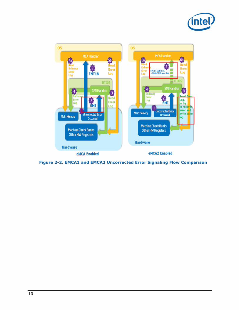
10
Figure 2-2. EMCA1 and EMCA2 Uncorrected Error Signaling Flow Comparison
11
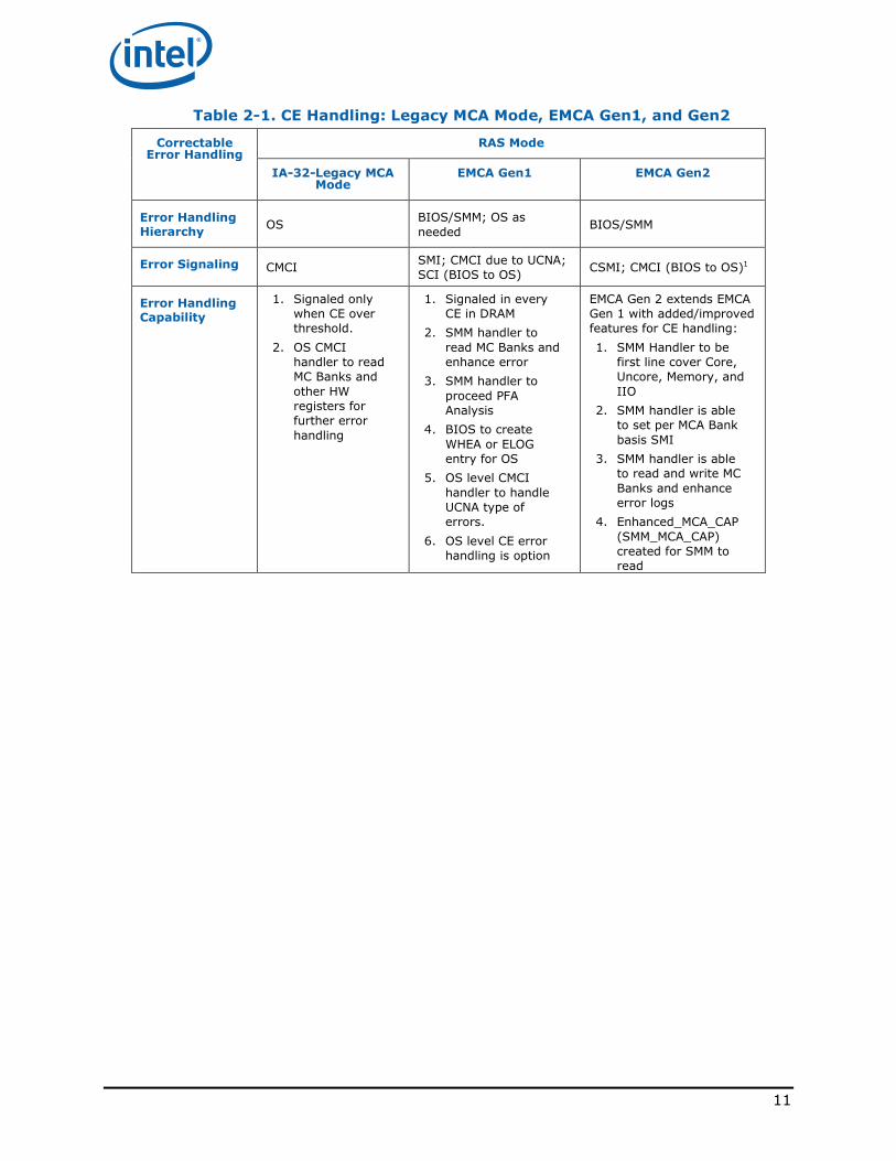
Table 2-1. CE Handling: Legacy MCA Mode, EMCA Gen1, and Gen2
Correctable Error Handling
RAS Mode
IA-32-Legacy MCA Mode
EMCA Gen1 EMCA Gen2
Error Handling Hierarchy
OS BIOS/SMM; OS as
needed BIOS/SMM
Error Signaling CMCI SMI; CMCI due to UCNA;
SCI (BIOS to OS) CSMI; CMCI (BIOS to OS)1
Error Handling Capability
1. Signaled only
when CE over
threshold.
2. OS CMCI
handler to read
MC Banks and
other HW
registers for
further error
handling
1. Signaled in every
CE in DRAM
2. SMM handler to
read MC Banks and
enhance error
3. SMM handler to
proceed PFA
Analysis
4. BIOS to create
WHEA or ELOG
entry for OS
5. OS level CMCI
handler to handle
UCNA type of
errors.
6. OS level CE error
handling is option
EMCA Gen 2 extends EMCA
Gen 1 with added/improved
features for CE handling:
1. SMM Handler to be
first line cover Core,
Uncore, Memory, and
IIO
2. SMM handler is able
to set per MCA Bank
basis SMI
3. SMM handler is able
to read and write MC
Banks and enhance
error logs
4. Enhanced_MCA_CAP
(SMM_MCA_CAP)
created for SMM to
read
12
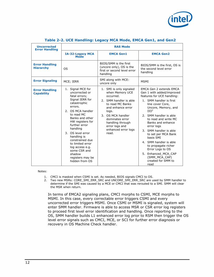
Table 2-2. UCE Handling: Legacy MCA Mode, EMCA Gen1, and Gen2
Uncorrected Error Handling
RAS Mode
IA-32-Legacy MCA Mode
EMCA Gen1 EMCA Gen2
Error Handling Hierarchy OS
BIOS/SMM is the first
(uncore only), OS is the
first or second level error
handling
BIOS/SMM is the first, OS is
the second level error
handling
Error Signaling MCE; IERR SMI along with MCE:
uncore only MSMI
Error Handling Capability
1. Signal MCE for
uncorrected or
fatal errors;
Signal IERR for
catastrophic
errors.
2. OS MCA handler
to read MC
Banks and other
HW registers for
further error
handling
3. OS level error
handling is
constrained due
to limited error
log access e.g.
some CSR and
shadow
registers may be
hidden from OS
1. SMI is only signaled
when Memory UCE
occurred.
2. SMM handler is able
to read MC Banks
and enhance error
logs.
3. OS MCA handler
dominates error
handling through
error logs and
enhanced error logs
read.
EMCA Gen 2 extends EMCA
Gen 1 with added/improved
features for UCE handling:
1. SMM handler is first
line cover Core,
Uncore, Memory, and
IIO2
2. SMM handler is able
to read and write MC
Banks and enhance
error logs
3. SMM handler is able
to set per MCA Bank
basis SMI
4. SMM handler is able
to propagate richer
Error Logs to OS
5. Enhanced_MCA_CAP
(SMM_MCA_CAP)
created for SMM to
read
Notes:
1. CMCI is masked when CSMI is set. As needed, BIOS signals CMCI to OS. 2. Two new MSRs: CORE_SMI_ERR_SRC and UNCORE_SMI_ERR_SRC are used by SMM handler to
determine if the SMI was caused by a MCE or CMCI that was rerouted to a SMI. SMM will clear the MSR when return.
In terms of EMCA2 signaling plans, CMCI morphs to CSMI, MCE morphs to
MSMI. In this case, every correctable error triggers CSMI and every
uncorrected error triggers MSMI. Once CSMI or MSMI is signaled, system will
enter SMM handler. Firmware is able to access MSR or CSR error log registers
to proceed first level error identification and handling. Once reporting to the
OS, SMM handler builds L1 enhanced error log prior to RSM then trigger the OS
level error signals such as CMCI, MCE, or SCI for further error diagnosis or
recovery in OS Machine Check handler.
13
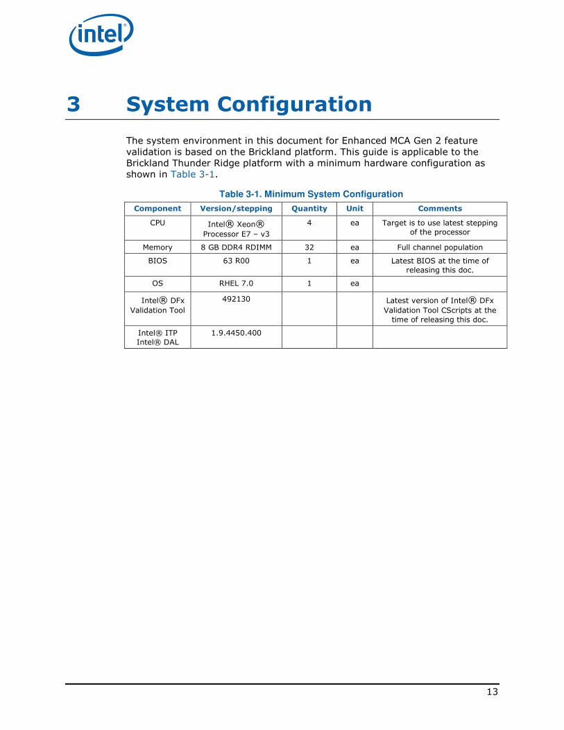
3 System Configuration
The system environment in this document for Enhanced MCA Gen 2 feature
validation is based on the Brickland platform. This guide is applicable to the
Brickland Thunder Ridge platform with a minimum hardware configuration as
shown in Table 3-1.
Table 3-1. Minimum System Configuration
Component Version/stepping Quantity Unit Comments
CPU Intel® Xeon®
Processor E7 – v3
4 ea Target is to use latest stepping
of the processor
Memory 8 GB DDR4 RDIMM 32 ea Full channel population
BIOS 63 R00 1 ea Latest BIOS at the time of
releasing this doc.
OS RHEL 7.0 1 ea
Intel® DFx
Validation Tool
492130 Latest version of Intel® DFx
Validation Tool CScripts at the
time of releasing this doc.
Intel® ITP
Intel® DAL
1.9.4450.400
14
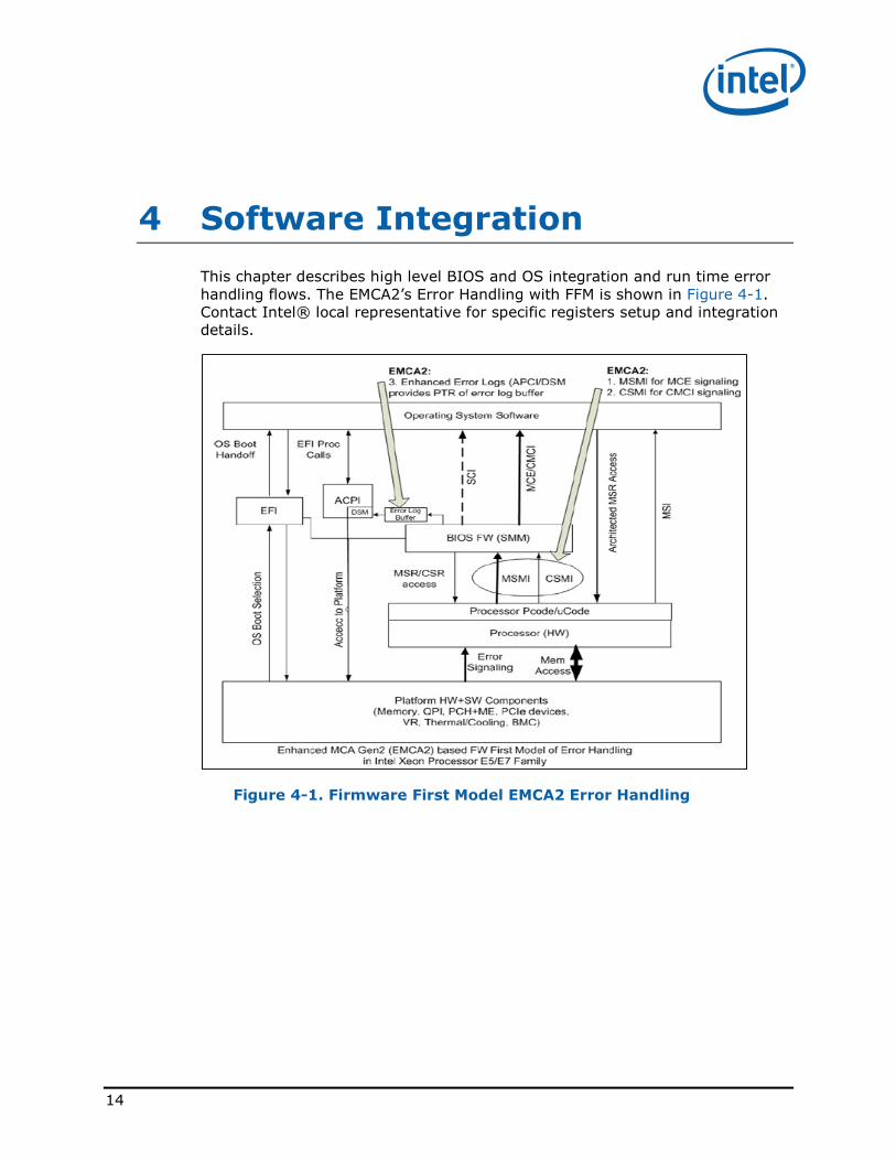
4 Software Integration
This chapter describes high level BIOS and OS integration and run time error
handling flows. The EMCA2’s Error Handling with FFM is shown in Figure 4-1.
Contact Intel® local representative for specific registers setup and integration
details.
Figure 4-1. Firmware First Model EMCA2 Error Handling
15
4.1 Feature Setup Flow
To enable EMCA Gen2, follow setup procedure:
1. In SMM handler, setup EMCA Gen 2
a. In MCi_CTL2 MSR registers, set CSMI in CMCI_CTL
b. In MCi_CTL2 MSR registers, set MSMI in MCE_CTL.
Note that EMCA may encounter race condition when CSMI and MSMI
come together for memory poison consumption. Option is to keep CMCI
and morph MCE to MSMI only.
2. Install SMI MCE Handler
3. Program SMM Handler entry to 32b protected mode
The purpose of this feature:
a. Enable robust BIOS MCA Handling. This allows the SMM machine
check handler to be called on a machine check event instead of
causing the processor to enter the shutdown state and asserting the
IERR# signal.
b. EMCA may encounter race condition when CSMI and MSMI come
together for memory poison consumption.
4. Build up enhanced error logging data structure. See section 4.2 and 4.3
16
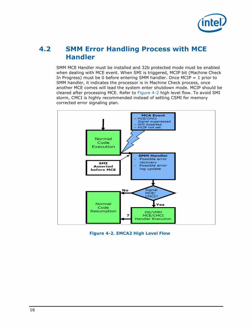
4.2 SMM Error Handling Process with MCE
Handler
SMM MCE Handler must be installed and 32b protected mode must be enabled
when dealing with MCE event. When SMI is triggered, MCIP bit (Machine Check
In Progress) must be 0 before entering SMM handler. Once MCIP = 1 prior to
SMM handler, it indicates the processor is in Machine Check process, once
another MCE comes will lead the system enter shutdown mode. MCIP should be
cleared after processing MCE. Refer to Figure 4-2 high level flow. To avoid SMI
storm, CMCI is highly recommended instead of setting CSMI for memory
corrected error signaling plan.
Figure 4-2. EMCA2 High Level Flow
17
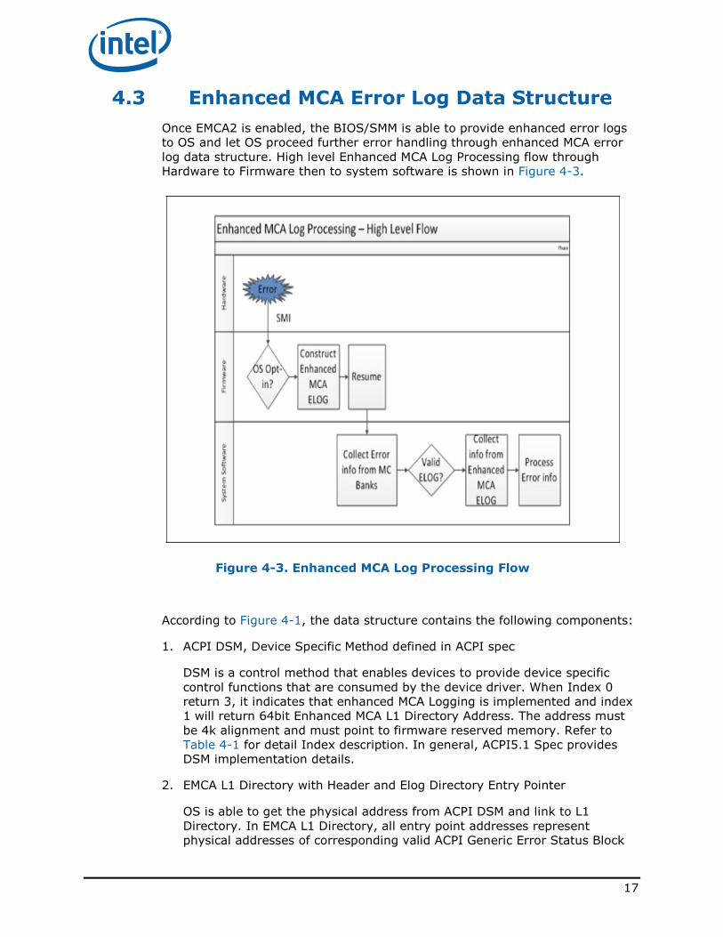
4.3 Enhanced MCA Error Log Data Structure
Once EMCA2 is enabled, the BIOS/SMM is able to provide enhanced error logs
to OS and let OS proceed further error handling through enhanced MCA error
log data structure. High level Enhanced MCA Log Processing flow through
Hardware to Firmware then to system software is shown in Figure 4-3.
Figure 4-3. Enhanced MCA Log Processing Flow
According to Figure 4-1, the data structure contains the following components:
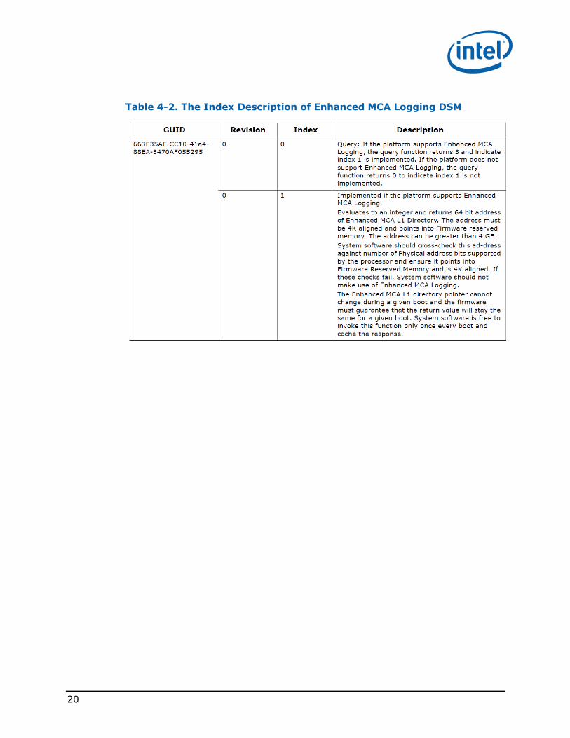
1. ACPI DSM, Device Specific Method defined in ACPI spec
DSM is a control method that enables devices to provide device specific
control functions that are consumed by the device driver. When Index 0
return 3, it indicates that enhanced MCA Logging is implemented and index
1 will return 64bit Enhanced MCA L1 Directory Address. The address must
be 4k alignment and must point to firmware reserved memory. Refer to
Table 4-1 for detail Index description. In general, ACPI5.1 Spec provides
DSM implementation details.
2. EMCA L1 Directory with Header and Elog Directory Entry Pointer
OS is able to get the physical address from ACPI DSM and link to L1
Directory. In EMCA L1 Directory, all entry point addresses represent
physical addresses of corresponding valid ACPI Generic Error Status Block
18
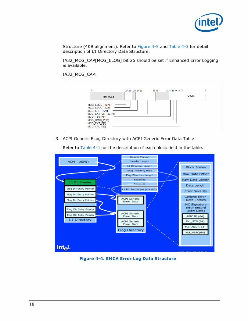
Structure (4KB alignment). Refer to Figure 4-5 and Table 4-3 for detail
description of L1 Directory Data Structure.
IA32_MCG_CAP[MCG_ELOG] bit 26 should be set if Enhanced Error Logging
is available.
IA32_MCG_CAP:
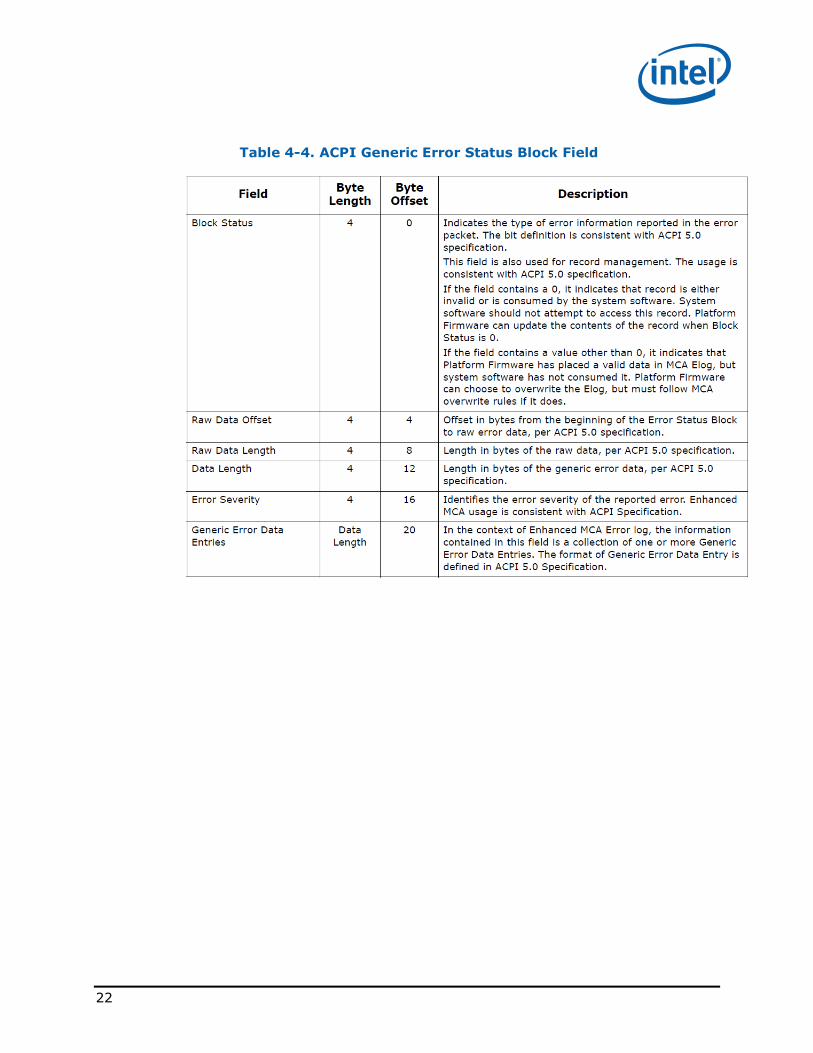
3. ACPI Generic ELog Directory with ACPI Generic Error Data Table
Refer to Table 4-4 for the description of each block field in the table.
Figure 4-4. EMCA Error Log Data Structure
19
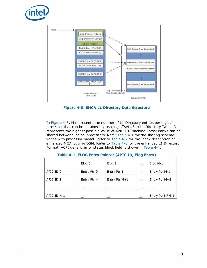
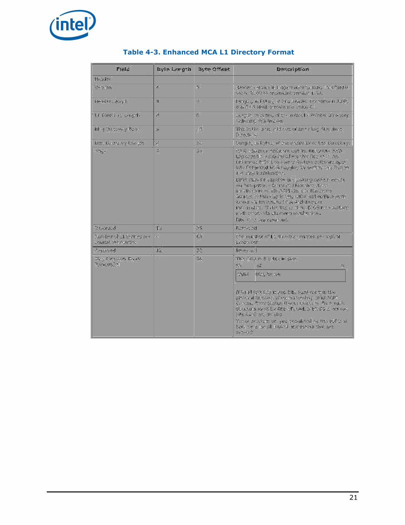
Figure 4-5. EMCA L1 Directory Data Structure
In Figure 4-5, M represents the number of L1 Directory entries per logical
processor that can be obtained by reading offset 48 in L1 Directory Table. N
represents the highest possible value of APIC ID. Machine Check Banks can be
shared between logical processors. Refer Table 4-1 for the sharing scheme
varies with processor model. Refer to Table 4-2 for the index description of
enhanced MCA logging DSM. Refer to Table 4-3 for the enhanced L1 Directory
Format. ACPI generic error status block field is shown in Table 4-4.
Table 4-1. ELOG Entry Pointer (APIC ID, Elog Entry)
Elog 0 Elog 1 ….. Elog M-1
APIC ID 0 Entry Ptr 0 Entry Ptr 1 …. Entry Ptr M-1
APIC ID 1 Entry Ptr M Entry Ptr M+1 …. Entry Ptr M+2
…… …. …. …. ….
APIC ID N-1 …. …. …. Entry Ptr N*M-1
20
Table 4-2. The Index Description of Enhanced MCA Logging DSM
21
Table 4-3. Enhanced MCA L1 Directory Format
22
Table 4-4. ACPI Generic Error Status Block Field
23
5 Intel® DFx Validation Recipes
This chapter provides Intel® ITP CScripts Validation Recipes. Contact Intel®
local representative regarding CScripts installation process and system
integration.
5.1 BIOS Setup
The reference BIOS setup is based on the BIOS version used in Intel® Xeon
Processor E7 – 8800/4800/2800 v3 based Customer Reference Platform.
Customers may need to contact BIOS vendor or Intel® local representative for
detail setup.
Enter BIOS setup page of “EDKII Menu -> Advanced -> System Event Log”,
and set below BIOS setup options:
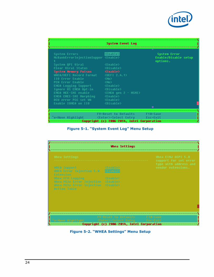
EDKII Menu -> Advanced -> System Event Log: � System Errors: Enable
� System Memory Poison: Enable
� EMCA Logging Support: Enable
� Ignore OS EMCA Opt-in: Disable
� EMCA MCE-SMI enable: EMCA gen 2 - MSMI
� EMCA CMCI-SMI Morphing: Disable
EDKII Menu -> Advanced -> System Event Log -> Whea Settings � WHEA Support: Enable
� WHEA Error Injection 5.0 Extension: Disable
� WHEA FFM Logging: Enable
Note: “Ignore OS EMCA Opt-in” option is to let the BIOS log MCA errors regardless OS is EMCA2
aware of or not. This setting will enable BIOS SMI handler to log the MCA errors at designated
memory location even if the OS is not EMCA2 ready and doesn’t set the “flag” bit in the eLOG
header entry.
24
Figure 5-1. “System Event Log” Menu Setup
Figure 5-2. “WHEA Settings” Menu Setup
25
5.2 The Process to EMCA L1 Directory
Address
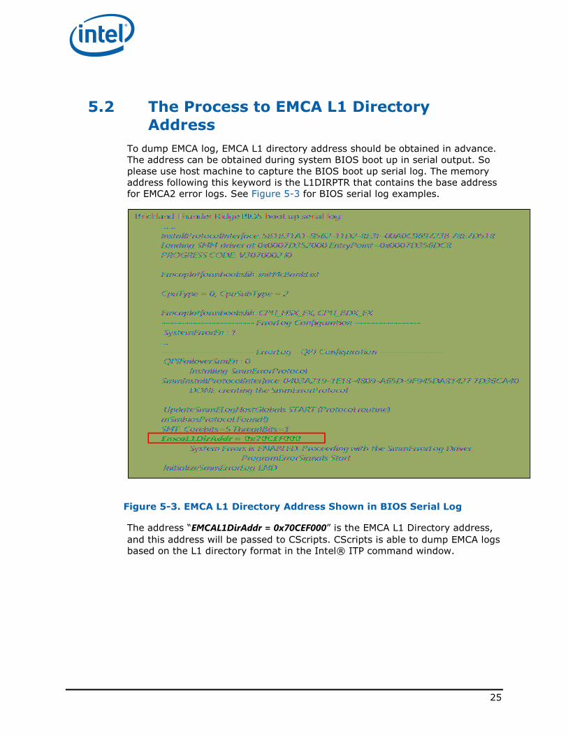
To dump EMCA log, EMCA L1 directory address should be obtained in advance.
The address can be obtained during system BIOS boot up in serial output. So
please use host machine to capture the BIOS boot up serial log. The memory
address following this keyword is the L1DIRPTR that contains the base address
for EMCA2 error logs. See Figure 5-3 for BIOS serial log examples.
Figure 5-3. EMCA L1 Directory Address Shown in BIOS Serial Log
The address “EMCAL1DirAddr = 0x70CEF000” is the EMCA L1 Directory address,
and this address will be passed to CScripts. CScripts is able to dump EMCA logs
based on the L1 directory format in the Intel® ITP command window.
26
5.3 Intel® DFx Validation Flow
Before proceeding, ensure Intel® DFx Validation Tool CScripts were built with
the latest update version. Make the system boot to shell and launch CScripts.
For detail commands in following steps, contact Intel® local representative for
further support.
Pre-test Setup and Check:
Step 1: Set up EMCA2 in BIOS menu, see Section 5.1 .
Step 2: Get the EMCA L1 Directory Address in BIOS serial log
“EMCAL1DirAddr = 0x75010000”, see Section 5.2.
Step 3: Set all ITP breaks are 0
Ensure ITP is stable with Haswell-EX:
a. Initial break, initbreak=0
b. Shutdown break, shutdownbreak=0
c. Machine Check Break, machinecheckbreak=0
Step 4: Import EMCA2 CScripts
Step 5: Confirm RAS Mode and Memory Channel Operation Mode Settings
Step 6: Check EMCA2 capability
a. Check MCE and CMCI morph to SMI setting: mce_ctl=1 and
cmci_ctl=1
b. PCU Viral mode propagation to MSMI: EMCA_mode=1
c. Check Ubox IERR transferred to MSMI
d. Show The Summary Table
Step 7: Check 32b protected mode setting.
Error Injection:
Step 8: Confirm no error in the log
Step 9: Set SMM entry and exit break
Step 9: Inject uncorrected error to target DIMM location
Ensure MCIP at IA32_MCG_STATUS is set correct
Step 10: Consume the error through memory read
Hit EMCA2 SMM entry break:
Step 11: Detect MSMI event
Proceed Error Dump
27
Step 12 Proceed error dump then let system go
Hit EMCA2 SMM exit break:
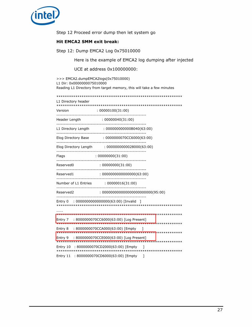
Step 12: Dump EMCA2 Log 0x75010000
Here is the example of EMCA2 log dumping after injected
UCE at address 0x100000000:
>>> EMCA2.dumpEMCA2logs(0x75010000)
L1 Dir: 0x0000000075010000
Reading L1 Directory from target memory, this will take a few minutes
************************************************************
L1 Directory header
************************************************************
Version : 00000100(31:00)
------------------------------------------------------------
Header Length : 00000040(31:00)
------------------------------------------------------------
L1 Directory Length : 000000000000B040(63:00)
------------------------------------------------------------
Elog Directory Base : 0000000070CC6000(63:00)
------------------------------------------------------------
Elog Directory Length : 0000000000028000(63:00)
------------------------------------------------------------
Flags : 00000000(31:00)
------------------------------------------------------------
Reserved0 : 00000000(31:00)
------------------------------------------------------------
Reserved1 : 0000000000000000(63:00)
------------------------------------------------------------
Number of L1 Entries : 00000016(31:00)
------------------------------------------------------------
Reserved2 : 000000000000000000000000(95:00)
------------------------------------------------------------
Entry 0 : 0000000000000000(63:00) [Invalid ]
************************************************************
…….
************************************************************
Entry 7 : 8000000070CC6000(63:00) [Log Present]
************************************************************
Entry 8 : 8000000070CCA000(63:00) [Empty ]
************************************************************
Entry 9 : 8000000070CCE000(63:00) [Log Present]
************************************************************
Entry 10 : 8000000070CD2000(63:00) [Empty ]
************************************************************
Entry 11 : 8000000070CD6000(63:00) [Empty ]
28
6 Linux*--Based Validation
Recipes
This chapter provides Linux*--Based Validation Recipes. Contact Intel® local
representative for Linux*--Based Validation tools installation process.
6.1 Persistent Memory Correctable Error
Validation Recipe
Prior to proceeding the validation recipes, ensure the test environment was
built correctly with recommended linux kernel, configurations as well as tool
kits that were located in a specific folder on SUT.
Step 1: Set up EMCA2 in BIOS menu, see Section 5.1
Step 2: Boot to Linux
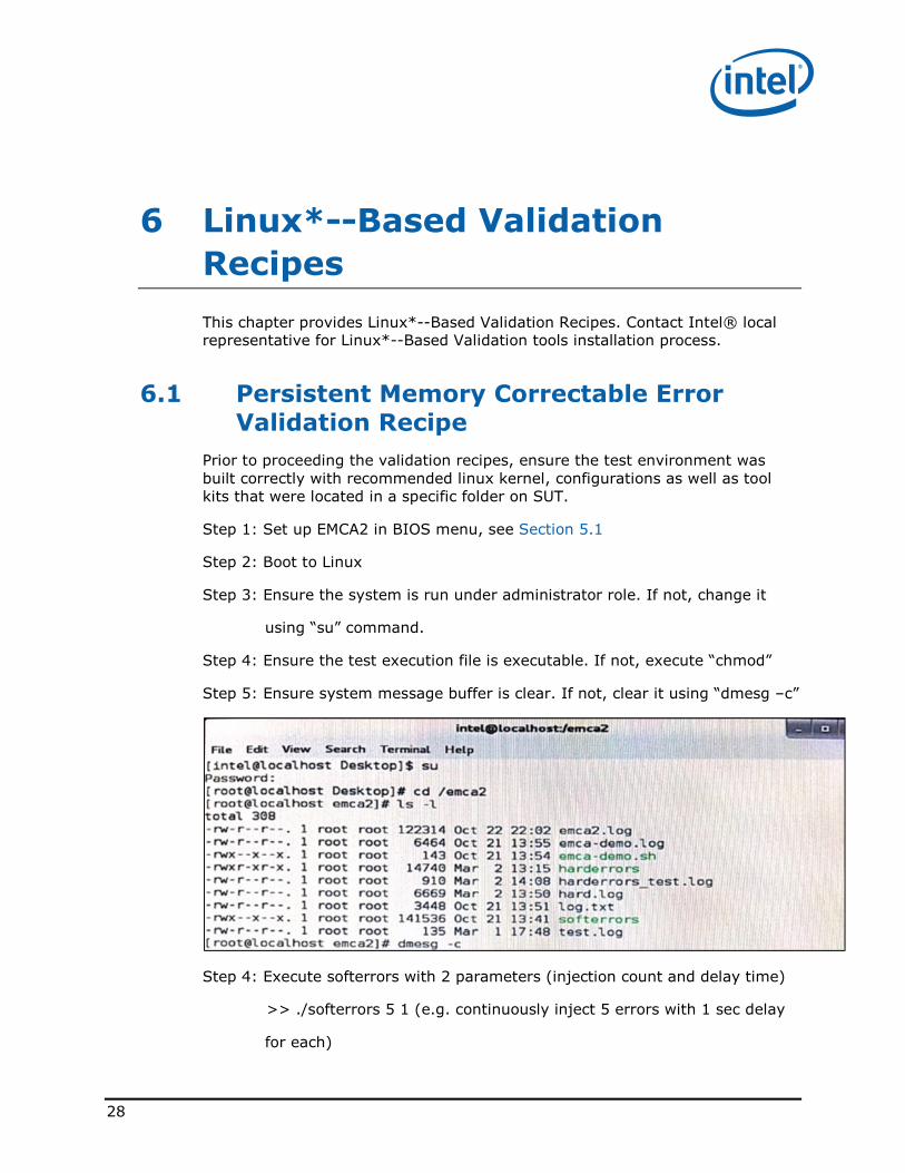
Step 3: Ensure the system is run under administrator role. If not, change it
using “su” command.
Step 4: Ensure the test execution file is executable. If not, execute “chmod”
Step 5: Ensure system message buffer is clear. If not, clear it using “dmesg –c”
Step 4: Execute softerrors with 2 parameters (injection count and delay time)
>> ./softerrors 5 1 (e.g. continuously inject 5 errors with 1 sec delay
for each)

29
Step 5: Monitor BIOS serial log output (option)
Step 6: Check error log through system message buffer
>> dmesg
6.2 Persistent Memory Uncorrectable Non
Fatal Error Validation Recipe
30
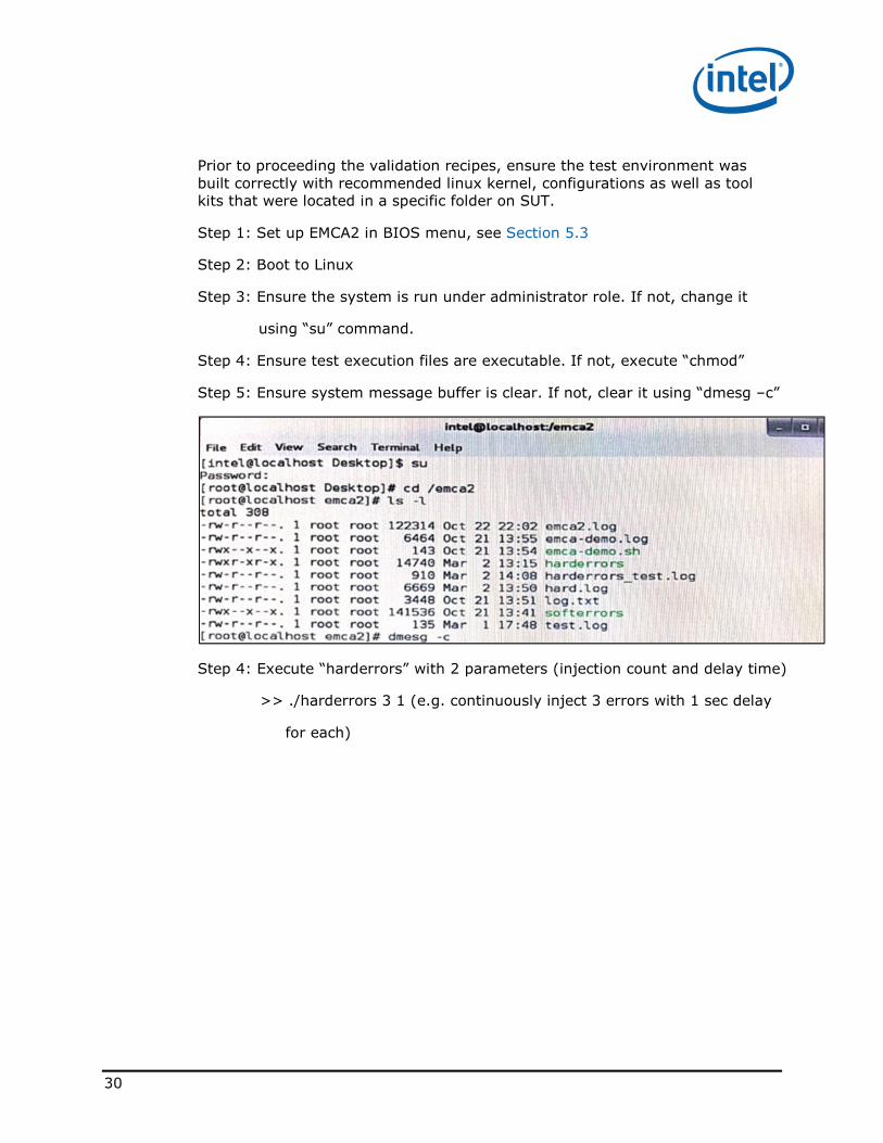
Prior to proceeding the validation recipes, ensure the test environment was
built correctly with recommended linux kernel, configurations as well as tool
kits that were located in a specific folder on SUT.
Step 1: Set up EMCA2 in BIOS menu, see Section 5.3
Step 2: Boot to Linux
Step 3: Ensure the system is run under administrator role. If not, change it
using “su” command.
Step 4: Ensure test execution files are executable. If not, execute “chmod”
Step 5: Ensure system message buffer is clear. If not, clear it using “dmesg –c”
Step 4: Execute “harderrors” with 2 parameters (injection count and delay time)
>> ./harderrors 3 1 (e.g. continuously inject 3 errors with 1 sec delay
for each)
31
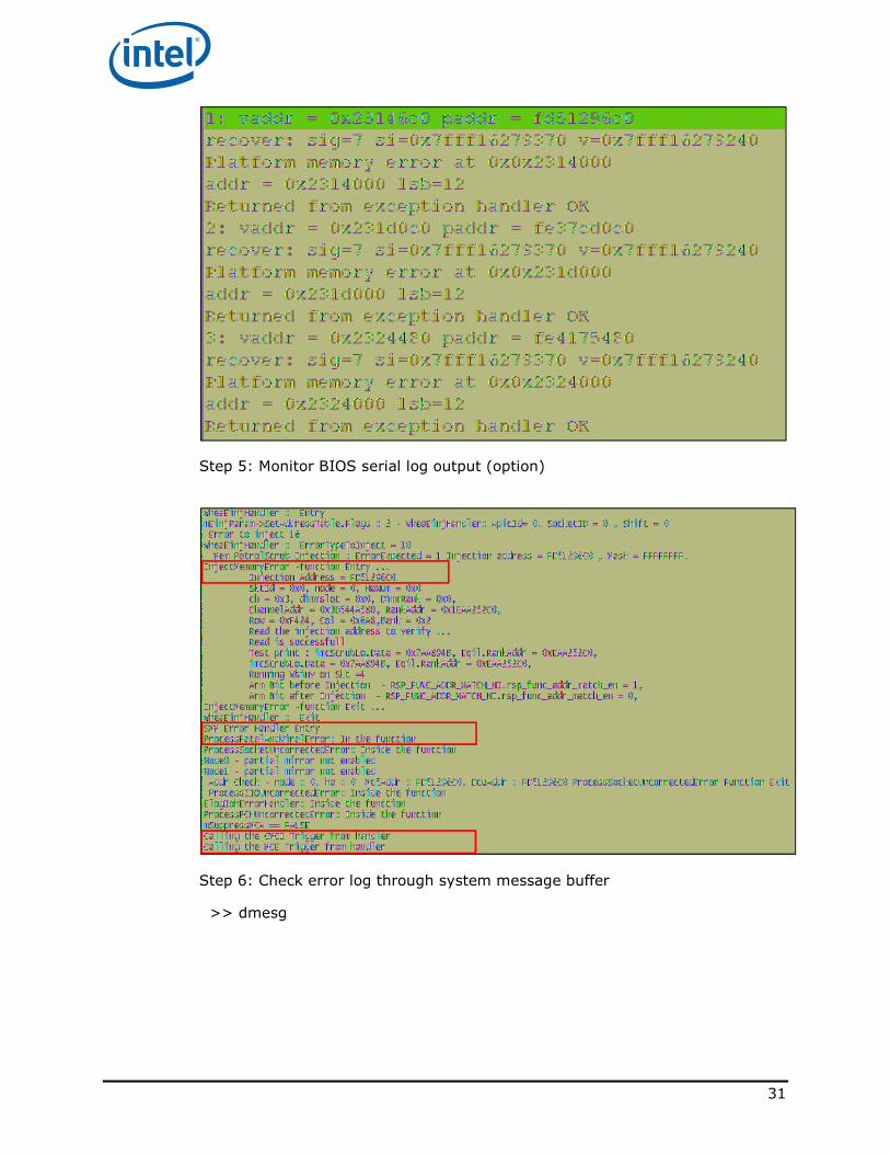
Step 5: Monitor BIOS serial log output (option)
Step 6: Check error log through system message buffer
>> dmesg
32
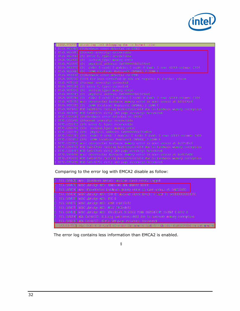
Comparing to the error log with EMCA2 disable as follow:
The error log contains less information than EMCA2 is enabled.
§