reliability attributes of microprocessors...
TRANSCRIPT

RELIABILITY ATTRIBUTES OF MICROPROCESSORS AND
MICROCOMPUTERS
M icroprocessors are im portant devices now a days and the ir reliability
is an im portant problem . Reliability is the attribute to w ork in a lucid m anner in the
given tim e w ithout any fault. Reliability has large num ber o f characteristic
com ponents in w hich no errors are found in the w orking. C om puter softw are
re liab ility has m any attributes in which a program m ust run accurately . In this study
the researcher has developed the logic diagram to find the reliab ility o f the, large
num ber o f com puters. The m aterials and the ir ra te o f deterioration are obtained.
M aterial deterioration in natural, forced and pollution outage a re obtained.
M arK ove process is used to calculate the reliab ility o f com puters. M ost often tw o
fau lts are faced in the com puter, one is the short c ircu it and o ther open circuit.
F ourteen typical m icroprocessors are taken in the study to find the ir M TB F, X, R
and P. The R epair rate, M aintainability , repairab iiity and availab ility are
calculated in the average numbers.
2.1 MATHEMATICAL MODELLING
The open circu it and short circuit m odes can be sim ulated to obtain the
probability o f failure o f the devices. O ne can form a vector o f the param eters as
fo llow s :

Pi Probability o f failure in Open C ircuit mode
P2 Probability o f failure in Short C ircuit mode
X, Failure Rate o f O pen C ircuit Failure
= Failure Rate o f Short C ircu it Failure
W R epair Rate o f O pen C ircu it Failure
R epair R ate o f Short C ircuit Failure
••(2 . 1)
The probab ility P (t) a t any instan t t can be found by M arK ov m ethod.
The repair rate and failu re rate also can be determ ined corresponding to P(t). O ne
can w rite the fo llow ing equations using M arK ov m ethod :
dP(t)
dt
dP i
dt
d P 2
dt
= ( M + X 2 ) P (t) - m P i - \x2P2 = 0
X1 P(t) + W P1 = 0 ..(2.2)
= >»2 P(t) + H2P 2 = 0
M arK ov m ethod is w ell know n and the various param eters can be
u W '1'- ' Obtained by som e new a ssum ptions under the m odel developed by the researcher.
^ f ' f The equipm ent is opera ting initially and
P(t) = P(o) = 1
and P i(o ) = P2(o) = 0 ..(2.3)

The m aterial deterioration and FOR, NO R and POR concepts are assum ed in this
study to obtain
( S + m ) ( s + \±2 )
P =
S ( s2 + S( m + H2) + ( a.1 + *-2) + M-2̂ -1 + + H m 2)
T he m athem atical m odelling is given in the references 1 and 2 and
o ther concepts are taken from references 3 and 4. The logic diagram s are draw n by
in references I and 2 and follow ing equation is used for th is purpose also :
Failure ra te = I = Sam ple size estim ated from special tab les /
T he Risk = - XR
T able 2.1 represents som e data used fo r re liab ility o f m icroprocessors o f various
kinds. The reliability R is calcu lated using fa ilu re rate X w ith equation (2.6). The
failure rate is calcu lated using equation (2 .5). T he probability o f fa ilu re is P. The
availab ility A and M ain tainability M are calcu lated using rep a ir rate and
m aintenance actions per y ear respectively . T he approxim ate values o f X, R, P, A
and M are average values using exponentia l and W eibull d istribu tion functions.
a/help o f reference 5. T he failure rate is determ ined using the equation given
T set T im eSam ple size actually used *
M ean Life
E lem ent hour* 100 * 1 0 0 / ..(2.5)
N um ber o f devices
The reliability in a sim ple form w ould be :
R = e-M and P = 1 - e-M ..(2 .6 )

T A B L E 2.1
SN N am e o f C om puter X R P ?lR A M
1. Intel 8080/LSI M icroprocessor 0.5 .60 .40 .30 .5 .96
2. Intel 386 80/10 8048 0.4 .67 .33 .268 .54 .93
M icroprocessor on card
3. Intel 8748 M icroprocessor 0.39 .677 .323 .264 .56 .91
on chip
4. Intel 8085 M icroprocessor 0.32 .726 .274 .232 .61 .89
5. P D P -11/03 D igital equipm ent 0.3 .740 .26 .222 .66 .87
corporation
6 . Type 3850 Fair Child 0.29 .748 .252 .216 .69 .86
M icroprocessor System
7. E X O R C IS E R 0.2 0.818 .182 .1636 .72 .82
(M otorola M C 6800)
8 . M icrocom puter (A m erican 0.18 .8352 .1648 .150 .78 .72
m icrosystem Inc A M I 6800)
9. M ostek 3872 Single chip 0.12 .886 .114 .106 .81 .73
M icroprocessor AM I
10. PPS-4/1 A N D PPS-8 0.10 .904 .096 .0904 .88 .77
(R ockw ell International)
11. C O SM EC (C M O S 2 chip 0.08 .923 .077 .073 .89 .62
M icrokit RCA C D P (80))
12. C D P 1802 RCA .06 0.941 .059 .056 .91 0.61
13. Intersil IM 6100 .02 0.980 .02 .0196 .93 .59
14. Portable C om puter (IB M 5100) .01 0.990 .01 .0099 .96 .52

2.2 A STUDY OF VARIOUS TYPES OF COMPUTERS AND
THEIR RELIABILITY
A system atic study o f H ardw ired, logic array, calcu lator, large scale
com puters m inicom puters, m icrocom puters and m icroprocessors is m ade in
reference 1,2 , 3 and 4. The approxim ate failure rate can be obtained by the life
data test o f these com puters. The life is designed in the increasing order given in
table 2.2. The reliability o f an electrical equipm ent depends on the security and the
adequacy. The reliability is found and large num ber o f param eters such as physical
re liability , therm al re liability , electrical reliability and electron ic re liab ility are'
given the nam es, to various planes o r spaces o f param eters. T he tw o a ttribu tes o f
re liab ility are m odified accord ing to the c ircu it param eters and variab les o f the
com puters. The m odern m icroprocessors are 10,000 to 20,000 tim es m ore reliable
than the conventional d igital com puters.
The security o f a com puter is the capability to w ithstand d isturbances
arising from faults. T he structure o f a com puter w ill also determ ine the security.
The location o f relays, fuses and o ther pro tective gears will also govern the security
o f the com puters. T he security will (depend? upon the M SI or LSI ch ips. The p lug
in C PU unit cards o r LSI m em ory com ponents as RA M and R O M w ill give
security to the com puters.

T A B L E 2.2
SN N am e o f C om puter M TBF
Yrs.
X R P XR A M
1. Hardw ired 5 0.2 .818 .182 .1636 .82 .96
2 . FPLA Logic A rray 10 0.1 .9048 .0952 .09048 .89 .93
3. C alcu lator 15 .066 .935 .065 .06171 .92 .91
4. M icrocom puter 20 .05 .9512 .0488 .0475 .94 .88
5. M inicom puter 25 .04 .960 .04 .0384 .91 .86
6 . Large Scale C om puter 30 .033 .9672 .0328 .032 .91 .88
7. M icroprocessor 50 .02 .980 .02 .0196 .92 .82
The degradation in term s o f accuracy or failure for a given tim e, under
changes in environm ental cond itions in w hich they w ere intended to w ork w ill also
govern the reliability . T he security engineers w ill be responsib le fo r im plem enting
a secured perform ance o f program to ach ieve the reliability ob jec tives under the
stresses related to the w orking conditions. The re liab ility o f the program w ill be
described in^the) chap ter th ree o f the w ork. T he softw are reliability w ill depend on
the decoupling o f the m odules and independence o f the structures. T he analysis o f
the failure should be devised carefu lly s c ru tin iz e d and restrained against
conditions that m ay cause catastrophic physical destruction o f the system .
T he secured perform ance o f these new ly developed system s will
depend on the actual stage in the overall life o f the com pu ter w hen the test for

security is being m ade. Security is described in m any spaces w ith m any defin itions
but a c lear cut idea by the researcher is given :
d R dPSecurity = -------- = -------- = - AR = Risk ■•(2.7)
dt dt
> A ccording to th ird law o f N ew ton, every action has a reaction equal and opposite,
the Risk m ust be equal to security in m agnitude.
Security and adequacy are the tw o attributes o f the reliability . The
M TB F o f the com puters can be calculated for various days o f its life. In the early
periods w hich is called learning stage, the M TB F w ill be low, since the m ajor and
m inor defic iencies in fabrication are to be corrected by applying new techniques.
A utom atic m eans are also used to correct these deficiencies. The com puter is
subjected to cycles o f changes under various environm ental conditions. A fte r shake
dow n tim e the h igher security w ill be realized during the production . Production
period is the m ajor life o f the m icroprocessor. A fter seven years o f period w hich is
the end o f the life o f m icroprocessor obsolescence may begin to reduce the security
a t an increasing rate. In the area o f solid state m icrotechnology, the tu rn around
tim e for rein troduction o f higher perform ance system , m eeting im proved devices
w ill be m uch shorter than th is period. H ence the obsolenscence sta te w ill dictate
the rep lacem ent o f the device by its new im proved version, fo r the h ig h er standard
o f perform ance and not due to any increased probability o f failure. T h is is to be
d iscussed, since the reliability o f the M SI and LSI devices is on a continuously
increasing au tom atic test procedure (A T P) during the fabrication.
The b ipolar technology have brought the failure rate, X, and m ean tim e
before fa ilu re (M T B F ) to g reater im proved stage. S ince the X and M T B F are
inverse to each o ther therefore reducing the X, one can increase the M T B F o f the
m icroprocessor. The failure ra te m ay be reduced as low as 2.1 * 10*5 p er hou r to
0.5 * 10-5 p er hour , a t 25 °C am bient tem perature at confidence o f 60% . The
corresponding failure rates o f M O S technology w ill be slightly h igher ranging from

3.1 * 10-5 to 0.35 * 10-5 per hour. In the ease o f the failures m ode effects
analysis (FM EA ), failure effects on the m icroprocessors and connected devices
will be considered.
O ne requires detection o f failures effects and the ir correction . One
needs reliability logic diagram to ca lcu late the security o f the com puters. For
detailed analysis the logic diagram s are very im portant.
In the case o f failure m ode critica lity analysis (FM C A ), a com ponent
critically num ber is calculated for each m ajor com ponent in the system . O ne can
use the form ula to ca lcu late criticality num ber :
W here n = 1 , 2 , 3 -------j
a = Failure m ode ratio
(3 = P robability o f Failure effects
K-e = Environm ental ratio
p . Ka = O perational ratio
X = F ailure ra te o r F ailure p er O perating cycles
t = O perating tim e in hours o r cycles
The quality control o f LSI and V LSI in Japan is m ore superior-to chips
m anufactured in A m erica. T he percentage failure in m icroprocessors m ade by
Japan is 0.11% and failures o f equipm ent assem bly 0.008% . T he field failures
recorded is 0 .002% . The percentage o f fa ilu res in the case o f A m erican
m icroprocessor is 0 .54% , 0.11% and .008% for incom ing inspection , assem bly o f
equipm ents and in the field respectively. T he Japanese m icroprocessors are o f
h igher reliability devices as com pared to A m erican and the E uropean devices. The
C ..(2 .8 )
n=I
study o f m icroprocessors m anufactured in Europe have the failures 0.5% , 0.12%
and 0.0085% respectively for inspection, assem bly and in the field.
The security may be calculated by the connections in series or parallel.
T he series connection reduce the security in practical term s. The security o f all the
series connected devices may be zero as one o f the failure o f a device w ill paralHsey
the en tire path o f the electric current. T he com puter is v iew ed as resistance,
inductance and capacitance (R LC ) param eters w hich can be m easured by digital
m eters or m icroprocessor indicators o f RLC param eters. The continuity or
discontinu ity may be obtained by the M aggers or the insulation testers. On the
o ther hand the security o f the parallel c ircu its w ill be high.
2.3 ARCHITECHDRE OF A MICROPROCESSOR
FOR RELIABILITY
A typical architecture o f a sing le chip m icroprocessor as a CPU and
the support that goes w ith it presently on a sing le printed circu it board as dedicated
m icrocom puter system is represented in F ig 2.1.
Fig. 2.1 A rchitecture o f a Typical M icroprocessor for Reliability

PC stands for Program C ounter A ccum ulator Index Register. The SP
denotes Stack Pointer. RAM includes R egisters and ROM m ain m em ory. All
blocks are in parallel to the C ontrol Bus and the system is reliable.
I f the com ponents are in series the reliability w ould be :
Rt = R l R2 R 3 --------- Rn -(2-9)
For a parallel system o f com puter com ponents the reliability w ould be :
Rt = 1 - ( 1 - R l ) ( 1 - R2 ) ( 1 - R3 ) ------- (1 - Rn ) -(2 .10)
There are eight com ponents in the m icroprocessor o f diagram in
F ig 2.1. All com ponents are in parallel to the clock generator because they receive ;
d ifferen t electrical signals bu t sam e voltage across them . All have equal reliability ,
o f 0.88 then the series com bination w ould be 0.35963 and parallel com bination
w ould yield a reliability.
R = 1 - (.12 * .12 * .1 2 * .1 2 * .1 2 * .1 2 * .1 2 * .1 2 )
R = 1 - 4 .2998 * 10-8 » 99.99 ..(2.11)
The security o f the arch itecture may be calcu lated seeing the bus
connections and the connected system s. O ne can refer it as the security o f the
C entral Processing U nit (C PU ). The security studies are m ade fo r large scale
central com puter system , m edium scale leased com pu ter system s and
m inicom puters. The term m ain fram e is com m ercially used fo r the C PU in the case
o f general purpose d igital com puters.
T he reliability o f the CPU m ay depend on the typ ica l a rch itectu re o f
the system . The instructions from the stored conto l m em ory, from a RO M w ill be
decoded w ith the help o f decode and contro l unit and perform ed by circu its in one
o r m ore o ther devices. The clock generato r is a crystal control and gives tim ing and
synchronisation to the devices. The A rithm etic logic unit (A L U ) m akes arithm etic
and logic operations. The easily accessib le w orking m em ory stack is form ed by the
registers for m aking program s. The data are transferred from a tape or floppy disk
to the internal tem porary data storage. T he fast access R EA D /W R ITE random
access m em ory (R A M ) is used to store data. The RAM also form s a part o f the
m icroprocessor chip. Thus one can assum e com plete sequence o f w ork e ither in
series o r in parallel to calculate the security.
TTY
I/O
ROM
(2)
RAM
H igh Speed
Punch R eader
( 1 )
(3)
BusCentral (5)
A ddressR egister
5 MHZ Clock (4)
ROM(7)
ROM(8)
BD BC
(9)
Synch
nii!vALU
( 10)
BDBC
ROR1R2R3R4RS
SP R6PC R7
DMA(13)
(14)
(12)
U16M ultip lexD ecoder
Fig. 2.2 Typical M icrocom puter : G eneral Instrum ent C orporation
CP - 1600 M icroprocessor

The I/O B uffer provides tim ing and m ultiplexing, they are
bid irectional, e ither read in instructions and data into the built in RAM o f the
m icroprocessor from the keyboard o r a PROM or w rite data o r instructions on the
RAM or an extended external casette tape (cartridge) or floppy disk o r C R T
disp lay o r tele type prin ter (TTY ). The reliability and security will depend on the
o ther peripheral devices in the use and the ir m utual coupling and dependence.
T he m icroprocessor is iden tified as ALU plus control devices both
m aking it a C PU , w hile the m icrocom puter will in addition have the com plem ent o f
input, output and R O M /R A M m em ory dev ices to form it a dedicated com puter
system . The internal RA M form s the m ain m em ory o f m icrocom puter. The
accum ulator is a reg ister for special purposes and closely associated with
A rithm atic Logic U nit (A LU ). It is one o f the source to supply data for A LU . It
fo rm s an im m ediate tem porary destination fo r the results given by the ALU and the
reliability is calcu la ted due to the special purposes registers. T he eight
program m ing registers are organised as tw o index registers, four accum ulators ,
stack po in ter for F irst in F irst ou t (F IF O ) o r L ast in F irst out (L IFO ) fo r the
accum ulators registers and program counter. T he m em ory interface is m ade by
address buffer to supply to the control m em ory R A M . T his is w ith the address from
w hich to fetch the nex t instructions. R eliab ility is increased w ith security by
provid ing som e m icroprocessors w ith in terface adapters fo r d ifferen t k inds o f I/O
operations. The program flow can be changed and the special m odes o f operations
can be handled. In special cases a sing le m icrocom puter m ay form several
technologies such as PM O S, N M O S, C M O S, B ipolar, TTL, EC L and I2L. The
special interface chips m ay be used to solve such problem s o f voltage levels and
propagation tim es. E ighty instructions program m ed on a ROM m ay m ake I/O data,
ju s t like m em ory in interna] o r external R A M S. T he external M ass m em ory w ill be
provided by tape case ttes, cartridges, m ini floppy diskettes and m agnetic bubble
m em ory.
a . - -The com putation in A LU is perform ed in binary ^ rith m a tic m achine
language. T he w ell defined procedure o f com putation for a solu tion in ^ jn f im t^
num bers o f steps will be called A lgorithm . M ostly O ctal o r hexadecim al binary
coded decim al d igils are used for assem bly program coding. T he reliability o f the
H ardw ares and Softw ares w ould fo llow the superposition . T he coupling o f the
H ardw ares and Softw ares w ould be decided by the coding m odules, structures and
instructions.
The softw are reliability will be discussed separately and a m odel will
be developed fo r the total reliability o f the com puter. The softw are and hardw are
system s w ould be in parallel o r series, logic diagram will be developed for the
system s o f w orking.
, Ttye form ula (2 .8) is used to calculate the criticality num ber using the
failure rat£"data and effects o f Environm ental conditions on the com puters.
2.4 RELIABILITY AND SECURITY STUDIES OF ARCHITECTURE
OF A MICROPROCESSOR CP - 1600 NMOS
The m icroprocessor m ade by G eneral Instrum ent C orporation is
b rought to the study fo r reliability and security. All o ther indices o f availability ,
m aintainability , repairab ility and rep laceability can be obtained by using the
statistical data and survey m ade on the com puters. T his type o f m icroprocessor is
represen ted in Fig. 2 .1 . The adjo in ing supported system fo r e ither te lep rin ter or
h igh speed paper tape reader/punch constitu te a m icrocom puter system w hich is
represented in Fig. 2 .2 . T h is is a pow erful single chip 16-bit C PU and it is a
m inicom puter o f high reliability and security . It has e igh t high speed general
purpose 16-bit registers. T he 16-bit w ord length and four addressing m odes perm it
effic ien t access to 64 K bytes o f m em ory. T his is used w ith program on ROM and
data storage RAM or o ther peripheral devices. I/O data are m anipulated like that o f
m em ory by its 87 instructions i n ^ .2 seconds as an average. T he non errasable
RO M m em ory is cable to be ex tended up to 64 K b its tak ing a single 5 V olt supply.
T he readily available static RA M s are lim ited to capacity o f 16 bits. A lthough the
ALU is equipcd w ith 8 bit functionally but this particular m icroprocessor presents
a 16 bit arch itecture to the program.
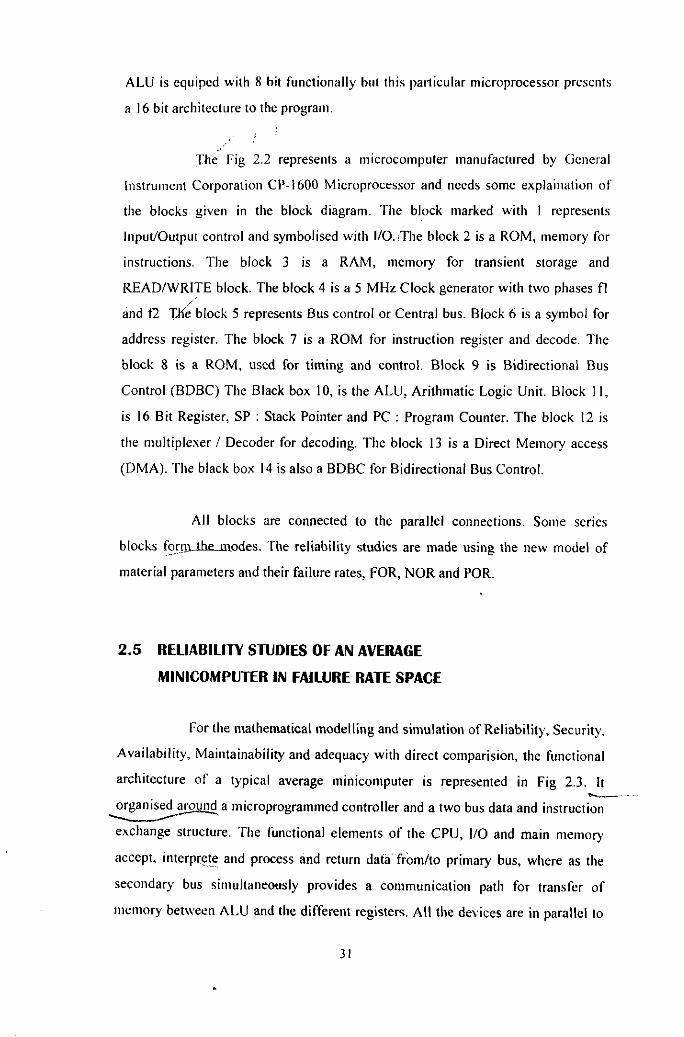
The Fig 2.2 represents a m icrocom puter m anufactured by General
instrum ent C orporation C P-1600 M icroprocessor and needs som e e x p lan a tio n o f
the blocks given in the block diagram . The block marked w ith 1 represents
Input/O utput control and sym bolised w ith I/O. T he block 2 is a ROM , m em ory for
instructions. T he block 3 is a R A M , m em ory for transient storage and
R EA D /W R ITE block. The block 4 is a 5 M H z C lock generator w ith tw o phases fl
and f2 The block 5 represents Bus control or C entral bus. B lock 6 is a sym bol for
address register. The block 7 is a ROM for instruction register and decode. The
b lock 8 is a ROM , used for tim ing and control. B lock 9 is B idirectional Bus
C ontrol (B D B C ) The Black box 10, is the A LU , A rithm atic Logic U nit. B lock 11,
is 16 Bit Register, SP : Stack Pointer and PC : Program Counter. The block 12 is
the m ultip lexer / D ecoder for decoding. The block 13 is a D irect M em ory access
(D M A ). The black box 14 is also a BDBC for B idirectional Bus Control.
All blocks are connected to the parallel connections. Som e series
blocks fo n ru tb e m odes. The reliability studies are m ade using the new m odel o f
m aterial param eters and their failure rates, FOR, N O R and POR.
2.5 RELIABILITY STUDIES OF AN AVERAGE
MINICOMPUTER IN FAILURE RATE SPACE
For the m athem atical m odelling and sim ulation o f R eliability , Security,
A vailability , M aintainability and adequacy with d irect com parision, the functional
arch itecture o f a typical average m inicom puter is represented in Fig 2.3. It
o rgan isedaroum J a m icroprogram m ed con tro ller and a two bus data and instruction
exchange structure. The functional e lem ents o f the C PU , I/O and m ain mem ory
accept, interprete and process and return data from /to prim ary bus, w here as the
secondary bus sim ultaneously provides a com m unication path for transfer o f
m em ory betw een ALU and the d ifferen t registers. A ll the devices are in parallel to

indicate any failure. T he security is the main m atter considered in the architecture.
The arch itecture o f m odern m icrocom puter is sim ilar and pow erful as com pared lo
m inicom puters.
T he prototype system s, tim e share assem blers, stand alone assem blers
and Editor, tim e share sim ulator/debugger, stand alone debugger and a m inim um o f
64 K W ord addressing capability , full environm ental capability to m eet rigorous
standards are m ade at extra expenditures. This im proves the re liab ility and security.
A single supply o f 5 V olts and m inim um operating pow er and on chip direct
m em ory access (D M A )/ Interrupt /d irect progress /capability are m ade for
reliability . All these m ake the m icrocom puter system as reliable and secured as the
m inicom puter.
N on-V olatile
\ l i Z /
M ainMemoryP’Rj Core
InterruptC ontrol
R9
^ V v
Function R egister
M icroM em ory
Rs
- A —
■ v y v —R?
Input/O utputC ontrol
I/O
- v V V 1*'
M icroprogram m ed C ontroller A LU CPU
R,
ExternalM assM em ory
P ro g ram * ^ status < TR egister R,
G eneral'1Purpose^R egisterStack
R2
^ C a t c h Pad ^ A c c u - " \ J l e g i s t c r / m ulator
Ri R4 Stack
Fig. 2.3 O rganisation of a Typical M inicom puter
For the Security Analysis aiul Reliability Studies

2.6 RELIABILITY OF MICROPROCESSORS
The Fig 2.3 can be assum ed a s the logic diagram tak ing the Bus as the
reference for the com pa riso n . The,.reference phasor is essential in the analysis o f
the reliability . The reliability may also be a relative term for the parts o f com puters.
T A B L E 2.3
M icroprocessor 1 In s tru c tio n R D esc rip tio n
8085 .01 ADD r .99 Add the contents o f the register r to the accumulator.
8085 .011 PUSH B .989 Put the content o f the register termed B on top o f the stack.
8085 .012 JNZ LOOP .988 Jump on non zero value in the accumulator to the address specified by loop.
8085 .0121 MVI C ,0 .987 Put a value o f O in the register C.
6800 .02 ROR .98 Rotate the Accumulator to the right.
6800 .021 STA A SIG .975 Store the value in the accumulator into a memory location identify as SIG.
6800 .03 DDA .97 Decimal adjustment the accumulator.
6800 .04 BEQ .96 Branch if equal.
8088 .044 MUL .956 Unsigned multiplication.
8088 .045 XCHG .955 Exchange register with accumulator.
8088 .05 DIV .951 Unsigned division.

T h e /T a b le 2.3 show s som e typical instructions that arc available w ith som e
-rnicroprocessors. T he flow o f inform ation in the CPU can be detected w hether in
series o r in parallel m ade by pulses flow. The program containing the necessary
sequence o f instructions to the CPU resides in the main m em ory o f the com puter.
/T h e location o f which is specified to the C PU in the form o f program counter. The
instructions are in the form o f low level com m ands which com prise the repertoire
o f any given C PU , called instruction set. The instruction set consists o f the
instructions for m oving the m em ory contents to perform arithm atic and logic
operations and o ther com m ands. A CPU fabricated as a single intergrated circuit
called ch ip , is called m icroprocessor and give greater reliability under m odel o f
spaces and volum es.
T able 2.4 stands for the reliability o f 41 m icroprocessors obtained by
the statistical basis and calculations m ade under the given m odel o f m aterial
arch itecture, spaces and M ass law o f m ixing o f the param eters. T he electrical
param eters RLC o r p, n t, er provide better reliability and on the spot by
m easuring the resistance, inductance and capacitance. T hese three param eters are
enough to m easure by digital LRC tand m eter in the laboratory to find reliability.
T hese com puters are described in books o f Rao62 and M athur63 and in the
reference 60 and 61.

T A B L E 2.4
SN Name o f M icroprocessor 1 R P 1 R M A Life
T
1. Intel 8086 M icroprocessor .011 .989 .88 .96 91
2. Intel 886 80/10 8048 M icroprocessor on card
.02 .98 .772 .97 50
3. Intel 8748 M icroprocessor .03 on chip
.97 .883 .98 33.3
4. Intel 8085 M icroprocessor
.022 .9782 .662 .97 45.45
5. PD P-11/03 D igital equipm ent corporation
.032 .968 .92 .96 31.25
6 . Type 3850 Fair C hild M icroprocessor System
.0331 .967 .772 .97 30.21
7. EX O R C ISER 8 bit (M otoro la M C 6800)
.04 .96 .92 .99 25
8 . M icrocom puter(A m erican m icrosystem
Inc 6800)
.042 .958 .722 0.96 23.8

SN N am e o f M ic ro p ro c e sso r 1 R P 1 K M A LifeT
9. M ostek 3872 Single chip M icroprocessor AM I
.033 .967 .923 .93 30.30
10. PPS-4/1 A N D P PS-8 (R ockw ell International)
.05 .9512 .776 .899 20
11. C O SM EC (C M O S 2 chip .052 M icrokit RCA C D P (8)
.9493 .882 .96 19.2
12. C D P 1802 RCA .06 .9417 .776 .95 16.66
13. Intersil IM 6100 .061 .9408 .882 .95 16.39
14. Portable C om puter (IB M 5100)
.07 .932 .778 .94 14.28
15. Intel 82 C 3 7 A -5 .012 .988 .776 0.98 83.33
16. Intel 8257/8257-5 .0012 .998 .827 .99 833.33
17. Intel 82380 .03 .970 .772 .98 33.3
18. Intel 82307 .0332 .967 .883 .97 30.12
19. Intel 82258 .04 .960 .662 .96 25
20. Intel 8051, 8-bit m icro contro ller
.052 .949 .772 .95 19.23

SN Name o f M icroprocessor 1 R 1» 1 R M A LifeT
21. Intel 8051 8 bit Single chip M icrocom puter
.012 .988 .882 .98 83.33
22. Intel 8096 16 bit Single ch ip m icrocom puter
.06 .941 .668 .95 16.66
23. Intel 8044 based on core
.07 .932 .778 .94 14.28
24. Intel 2920/2921 Single ch ip A nalog/digital S ignal processor
.08 .923 .772 .93 12.5
25. Intel 8089 8/16 bit H M O S I/O processor
.061 .940 .882 .93 16.39
26. Intel 82258 16 bit DM A C oprocessor
.082 .921 .772 .92 12.2
27. Intel 8087 N um eric data coprocessor
.077 .925 .662 .93 12.98
28. Intel 80387 D X 80 bit C H M O S IV
.065 .937 .779 .94 15.38
29. Intel 80387 Sx .088 .915 .82 .92 11.36

SN Name of M icroprocessor I R P I R M A LifeT
30. Intel 82786
31. Intel 82706
32. Intel 8276 C R T Controlled
33. Intel 82716
34. Intel 8275
.0412 .9696
.052 .949
.0662 .936
.017 .983
.021 .979
.92 .97
.96 .95
.778 .94
.98 .99
.772 .98
.662 .97
.778 .92
.882 .94
.882 .97
.778 .96
.882 .98
.93 .94
35. Intel 80486 32 bit C PU .033 .967
36. M otorola 6845 C R T .088 .915C ontroller
37. M otorola M C 68881 .066 .936floating poin t C oprocessor
38. M otorola 68042 32 bit .036 .964processor
39. M otorola M C 88100 .044 .95732 bit RISKprocessor
40. M otorola 68020 32 bit .027 .973M icroprocessor
41. M otorola 68000 16 bit .066 .936M icroprocessor
24.27
9.23
15.1
58.82
47.619
30.3
11.36
15.15
27.77
22.72
37.03
15.15