release 0.3 olivier hériveaux - read the docs
TRANSCRIPT

scaffold DocumentationRelease 0.3
Olivier Hériveaux
Apr 05, 2019

Contents:
1 Getting started 31.1 Board tour . . . . . . . . . . . . . . . . . . . . . . . . . . . . . . . . . . . . . . . . . . . . . . . . 31.2 Connecting the board . . . . . . . . . . . . . . . . . . . . . . . . . . . . . . . . . . . . . . . . . . . 41.3 Using the Python API . . . . . . . . . . . . . . . . . . . . . . . . . . . . . . . . . . . . . . . . . . 4
2 Kits 72.1 Breadboard kit . . . . . . . . . . . . . . . . . . . . . . . . . . . . . . . . . . . . . . . . . . . . . . 72.2 STM32F2 QFP64 kit . . . . . . . . . . . . . . . . . . . . . . . . . . . . . . . . . . . . . . . . . . . 72.3 Smartcard kit . . . . . . . . . . . . . . . . . . . . . . . . . . . . . . . . . . . . . . . . . . . . . . . 10
3 Scaffold peripherals 133.1 I/Os . . . . . . . . . . . . . . . . . . . . . . . . . . . . . . . . . . . . . . . . . . . . . . . . . . . . 133.2 Power module . . . . . . . . . . . . . . . . . . . . . . . . . . . . . . . . . . . . . . . . . . . . . . 153.3 LEDs module . . . . . . . . . . . . . . . . . . . . . . . . . . . . . . . . . . . . . . . . . . . . . . . 163.4 Version module . . . . . . . . . . . . . . . . . . . . . . . . . . . . . . . . . . . . . . . . . . . . . . 17
4 Python API 194.1 Main Scaffold API . . . . . . . . . . . . . . . . . . . . . . . . . . . . . . . . . . . . . . . . . . . . 194.2 STM32 API . . . . . . . . . . . . . . . . . . . . . . . . . . . . . . . . . . . . . . . . . . . . . . . 244.3 ISO7816 API . . . . . . . . . . . . . . . . . . . . . . . . . . . . . . . . . . . . . . . . . . . . . . . 26
5 Architecture 295.1 Communication protocol . . . . . . . . . . . . . . . . . . . . . . . . . . . . . . . . . . . . . . . . . 295.2 FPGA bus . . . . . . . . . . . . . . . . . . . . . . . . . . . . . . . . . . . . . . . . . . . . . . . . 305.3 FPGA bus bridge . . . . . . . . . . . . . . . . . . . . . . . . . . . . . . . . . . . . . . . . . . . . . 315.4 Output module . . . . . . . . . . . . . . . . . . . . . . . . . . . . . . . . . . . . . . . . . . . . . . 35
6 Building and flashing the FPGA bitstream 376.1 Prerequisites . . . . . . . . . . . . . . . . . . . . . . . . . . . . . . . . . . . . . . . . . . . . . . . 376.2 Building the bitstream . . . . . . . . . . . . . . . . . . . . . . . . . . . . . . . . . . . . . . . . . . 376.3 Flashing the FPGA . . . . . . . . . . . . . . . . . . . . . . . . . . . . . . . . . . . . . . . . . . . . 37
7 Indices and tables 41
Python Module Index 43
i

ii

scaffold Documentation, Release 0.3
Contents: 1

scaffold Documentation, Release 0.3
2 Contents:

CHAPTER 1
Getting started
Scaffold is a FPGA board made for security research on hardware embedded devices. It is capable of communicatingwith many circuits using standard protocols. It can be easily extended with new protocols by writing new transceiversin VHDL or Verilog language, and integrating it in the proposed scaffold global architecture. When exchangingmessages with the devices under tests, Scaffold can generate triggers for chosen commands, spy data on a bus orintercept and traffic.
Scaffold board also embeds special electronics tailored for hardware attacks:
• Sense resistor and analog amplifier for real-time current measurement
• FPGA safety protections against voltage glitch attacks
• Controllable power switches
• Fast power tearing capability, for emergency shutdown of the device under test
• Delay and pulse generators, allowing firing glitches or laser pulses.
An easy-to-use python API is provided to control the board.
1.1 Board tour
• A: USB2 link with host computer. Also used to power the board.
• B: Main board power switch.
• C: Switch the jumper to the right to power the board from an external 5 V power supply and not from the USB.
• D: External power supply for the platform socket.
• E: External power supply for the DUT socket.
• F: Adjustable voltage regulator for the platform socket. When the jumper is set on top position, this powersource is not used and the platform socket is powered from the external power supply.
3

scaffold Documentation, Release 0.3
• G: Adjustable voltage regulator for the DUT socket. When the jumper is set on top position, this power sourceis not used and the DUT socket is powered from the external power supply.
• H: Adjustable voltage regulator for the I/O bank of the FPGA connected to the platform and DUT sockets. Thisallows setting the correct voltage depending on the connected device. Supported voltage range goes from 1.5 Vup to 3.3 V.
• I: FPGA active serial connector for bitstream programmation. An USB blaster can be used to update the bit-stream.
• J: FPGA reset button. Push if the board enters error state.
• K: Switches to select Spy or Intercept mode for each I/O of the FPGA. In intercept mode, the signals of theplatform and DUT sockets are not connected anymore and the FPGA can act as a man in the middle circuit.
• L: Switches to enable 1 KOhm series protection resistors on the I/Os (at the cost of slew-rate). Shall be enabledwhen there is a risk to damage the FPGA, with high-voltage glitches for instance.
• M: Tearing input. Any positive edge will power-off the DUT immediately and shunt all I/Os to ground.
• N: A, B, C I/Os voltage standard selection between 3.3 V or 5 V.
• O: A, B, C I/O groups. Each group can be configured to have 3.3 V or 5 V I/Os. 5 V is suited to drive AlphanovTTL 50 Ohm laser sources (other 3.3 V I/Os can’t). All the I/Os of a same group are either in output or inputmode.
• P: D I/O group. Maximum voltage is 3.3 V. Those I/Os are connected to the platform and DUT sockets and areusually used to communicate with the target device and generate triggers. SMA connectors are provided for D0to D6.
• Q: Platform socket and power state LED.
• R: DUT socket and power state LED.
• S: Adjustable shunt resistor for power trace measurement.
• T: Output of the analog 11 X amplifier for power trace measurement.
1.2 Connecting the board
Connect the board with a micro-USB cable to your computer. Power-on the board using the power switch. Theoperating system shall detect the board as a USB-To-Serial device (COMx on Windows, /dev/ttyUSBx on linux). Itmay be necessary to install FTDI driver for some Windows versions.
1.3 Using the Python API
The file scaffold.py is the library which can be used to interact with Scaffold board.
from scaffold import Scaffold
# Connect to the board.# This will open the serial device and check for hardware versionscaffold = Scaffold('/dev/ttyUSB0')
# Configure UART0 for operationuart = scaff.uart0uart.baudrate = 115200
(continues on next page)
4 Chapter 1. Getting started

scaffold Documentation, Release 0.3
(continued from previous page)
# Connect UART0 signals to board pins# << operator connects signals. Left operand is the destination, right operand# is the source (the order is important)# In this example, D0 and D1 are configured as outputs, D2 is configured as an# input.scaffold.d0 << uart.txscaffold.d1 << uart.triggeruart.rx << scaffold.d2
# UART is now ready to useuart.send('Hello world !')
1.3. Using the Python API 5

scaffold Documentation, Release 0.3
6 Chapter 1. Getting started

CHAPTER 2
Kits
Some kits for specific applications with Scaffold are available.
2.1 Breadboard kit
The Scaffold breadboard provides solderable test points for all the DUT socket pins. It can be used to mount a setupwith any target.
2.2 STM32F2 QFP64 kit
This kit allows communicating with the embedded ST bootloader of STM32F2 devices. It is possible to write theFlash memory to load code, and then execute it after reset.
The socket FLIPPED-QPF64 can be used to mount a STM32F2 device on its backside. All pins of the package mustbe returned before inserting the device in the socket. Pin 1 of the target device is as shown in the figure above. Makesure the device is correctly inserted and all the needles of the socket touch their corresponding PIN.
2.2.1 Python API example
The class scaffold.stm32.STM32 of the Python API provides methods to communicate with the circuit andsetup tests very quickly.
from scaffold import Scaffoldfrom scaffold.stm32 import STM32
stm = STM32(Scaffold('/dev/ttyUSB0'))# Load some code into Flash memorystm.startup_bootloader()stm.extended_erase()
(continues on next page)
7

scaffold Documentation, Release 0.3
8 Chapter 2. Kits

scaffold Documentation, Release 0.3
2.2. STM32F2 QFP64 kit 9
scaffold Documentation, Release 0.3
(continued from previous page)
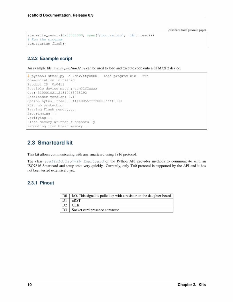
stm.write_memory(0x08000000, open('program.bin', 'rb').read())# Run the programstm.startup_flash()
2.2.2 Example script
An example file in examples/stm32.py can be used to load and execute code onto a STM32F2 device.
$ python3 stm32.py -d /dev/ttyUSB0 --load program.bin --runCommunication initiatedProduct ID: 0x0411Possible device match: stm32f2xxxxGet: 310001021121314463738292Bootloader version: 3.1Option bytes: ffaa0055ffaa0055ffff0000ffff0000RDP: no protectionErasing Flash memory...Programming...Verifying...Flash memory written successfully!Rebooting from Flash memory...
2.3 Smartcard kit
This kit allows communicating with any smartcard using 7816 protocol.
The class scaffold.iso7816.Smartcard of the Python API provides methods to communicate with anISO7816 Smartcard and setup tests very quickly. Currently, only T=0 protocol is supported by the API and it hasnot been tested extensively yet.
2.3.1 Pinout
D0 I/O. This signal is pulled up with a resistor on the daughter boardD1 nRSTD2 CLKD3 Socket card presence contactor
10 Chapter 2. Kits

scaffold Documentation, Release 0.3
2.3. Smartcard kit 11

scaffold Documentation, Release 0.3
12 Chapter 2. Kits

CHAPTER 3
Scaffold peripherals
3.1 I/Os
The Scaffold Python API allows controlling and reading the I/Os of the board. This can be useful, for instance, tocontrol the reset signal of a device under test. The following example shows how easy this can be done.
# Toggle D0 every second.for i in range(10):
scaffold.d0 << 0time.sleep(1)scaffold.d0 << 1time.sleep(1)
# Put D0 in high impedance statescaffold.d0 << Nonetime.sleep(1)
# Connect the output to the internal UART peripheral TX signal, and send a# message !scaffold.d0 << scaffold.uart0.txscaffold.uart0.send('Hello world!')
It is also possible to read the current electrical state of an input of the board:
if scaffold.d0.value == 1:print('Input is high!')
Finally, you can watch for events on an input. The event will be asserted if a 1 is detected. This works for short pulses(> 10 ns).
# Reset event flagscaffold.d0.event = 0# Wait some timetime.sleep(1)
(continues on next page)
13

scaffold Documentation, Release 0.3
(continued from previous page)
# Lookup event register to know if a pulse has been receivedif scaffold.d0.event == 1:
print('Event detected!')scaffold.d0.clear_event()
Warning: I/Os internals have been refactored in 0.3. Registers are not the same as in 0.2. Current API supportsboth 0.2 and 0.3 versions.
3.1.1 Internal registers
a0 0xe000a1 0xe010b0 0xe020b1 0xe030c0 0xe040c1 0xe050dn 0xe060 + 0x10 * n
base + 0x0000 value R/Wbase + 0x0001 config W
3.1.2 value register
7 6 5 4 3 2 1 0reserved event value
value Reading this bit will return current logical state on the I/O. Setting this bit has no effect.
event This bit is set to 1 when the I/O logical state changes. It can be reset by writing 0 to it.
3.1.3 config register
7 6 5 4 3 2 1 0reserved mode
This register allows customizing the output mode of an I/O.
mode Description0 Auto
The pin is driven by the routed peripheral.1 Open-drain
The pin is driven by the routed peripheral, but always acts as an open-collector.2 Push-only
The pin is driven by the routed peripheral, but is active only when a one is outputed.
14 Chapter 3. Scaffold peripherals

scaffold Documentation, Release 0.3
3.2 Power module
The power module controls two power supplies: the “platform” socket power supply and the “dut” socket powersupply. Each power supply can be turned on and off.
A positive input pulse on the “tearing” input of the board (SMA connector on the left side) will automatically power-offboth power supplies.
3.2.1 Python API example
# Turn DUT onscaffold.power.dut = 1 # True is also valid# Check current power supply status# (it may be off due to external tearing)if scaffold.power.dut: # Will return 0 or 1
print('DUT is still ON')# Turn DUT offscaffold.power.dut = 0 # False is also valid
The following example controls both power supplies at the same time.
# Turn on all power suppliesscaffold.power.all = 0b11# Check current power status of both power suppliesif (scaffold.power.all == 0b11):
print('Both power supplies are ON')# Turn off all power suppliesscaffold.power.all = 0b00
It is also possible to output the power enable signal to one of the IOs, for triggering or monitoring:
scaffold.d0 << scaffold.power.dut_trigger
For more API documentation, see scaffold.Power
3.2.2 Internal registers
control 0x0600
control register
7 6 5 4 3 2 1 0reserved platform dut
dut Write 1 to enable the DUT socket power supply. Write 0 to disable. This bit is cleared when the tearing input ishigh.
platform Write 1 to enable the platform socket power supply. Write 0 to disable. This bit is cleared when the tearinginput is high.
3.2. Power module 15
scaffold Documentation, Release 0.3
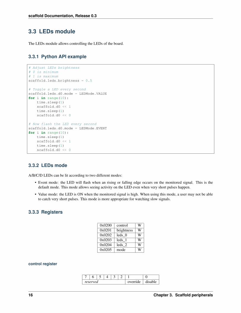
3.3 LEDs module
The LEDs module allows controlling the LEDs of the board.
3.3.1 Python API example
# Adjust LEDs brightness# 0 is minimum# 1 is maximumscaffold.leds.brightness = 0.5
# Toggle a LED every secondscaffold.leds.d0.mode = LEDMode.VALUEfor i in range(10):
time.sleep(1)scaffold.d0 << 1time.sleep(1)scaffold.d0 << 0
# Now flash the LED every secondscaffold.leds.d0.mode = LEDMode.EVENTfor i in range(10):
time.sleep(1)scaffold.d0 << 1time.sleep(1)scaffold.d0 << 0
3.3.2 LEDs mode
A/B/C/D LEDs can be lit according to two different modes:
• Event mode: the LED will flash when an rising or falling edge occurs on the monitored signal. This is thedefault mode. This mode allows seeing activity on the LED even when very short pulses happen.
• Value mode: the LED is ON when the monitored signal is high. When using this mode, a user may not be ableto catch very short pulses. This mode is more appropriate for watching slow signals.
3.3.3 Registers
0x0200 control W0x0201 brightness W0x0202 leds_0 W0x0203 leds_1 W0x0204 leds_2 W0x0205 mode W
control register
7 6 5 4 3 2 1 0reserved override disable
16 Chapter 3. Scaffold peripherals
scaffold Documentation, Release 0.3
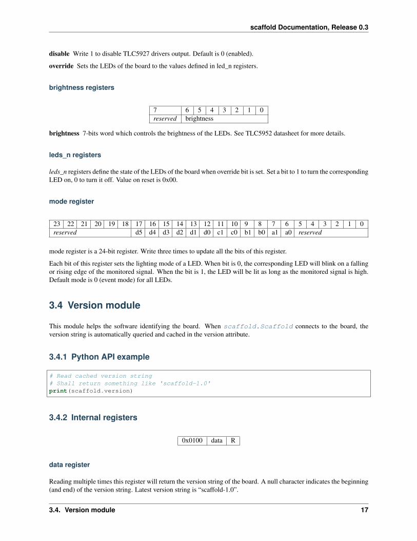
disable Write 1 to disable TLC5927 drivers output. Default is 0 (enabled).
override Sets the LEDs of the board to the values defined in led_n registers.
brightness registers
7 6 5 4 3 2 1 0reserved brightness
brightness 7-bits word which controls the brightness of the LEDs. See TLC5952 datasheet for more details.
leds_n registers
leds_n registers define the state of the LEDs of the board when override bit is set. Set a bit to 1 to turn the correspondingLED on, 0 to turn it off. Value on reset is 0x00.
mode register
23 22 21 20 19 18 17 16 15 14 13 12 11 10 9 8 7 6 5 4 3 2 1 0reserved d5 d4 d3 d2 d1 d0 c1 c0 b1 b0 a1 a0 reserved
mode register is a 24-bit register. Write three times to update all the bits of this register.
Each bit of this register sets the lighting mode of a LED. When bit is 0, the corresponding LED will blink on a fallingor rising edge of the monitored signal. When the bit is 1, the LED will be lit as long as the monitored signal is high.Default mode is 0 (event mode) for all LEDs.
3.4 Version module
This module helps the software identifying the board. When scaffold.Scaffold connects to the board, theversion string is automatically queried and cached in the version attribute.
3.4.1 Python API example
# Read cached version string# Shall return something like 'scaffold-1.0'print(scaffold.version)
3.4.2 Internal registers
0x0100 data R
data register
Reading multiple times this register will return the version string of the board. A null character indicates the beginning(and end) of the version string. Latest version string is “scaffold-1.0”.
3.4. Version module 17

scaffold Documentation, Release 0.3
18 Chapter 3. Scaffold peripherals

CHAPTER 4
Python API
4.1 Main Scaffold API
This page documents the main classes and methods of the Scaffold Python API.
Manipulating the attributes of the different modules of a Scaffold instance will read or write in the FPGA registers.Some registers may be cached by the Python API, so reading them does not require any communication with the boardand thus can be fast.
class scaffold.Scaffold(dev=’/dev/scaffold’)This class connects to a Scaffold board and provides access to all the device parameters and peripherals.
Variables
• uarts – list of scaffold.UART instance managing UART peripherals.
• i2cs – list of scaffold.I2C instance managing I2C peripherals.
• iso7816 – scaffold.ISO7816 instance managing the ISO7816 peripheral.
• pgens – list of four scaffold.PulseGenerator instance managing the FPGA pulsegenerators.
• power – scaffold.Power instance, enabling control of the power supplies of DUT andplatform sockets.
• leds – scaffold.LEDs instance, managing LEDs brightness and lighting mode.
• [a0,a1,b0,b1,c0,c1,d0,d1,d2,d3,d4,d5] – scaffold.Signal instancesfor connecting and controlling the corresponding I/Os of the board.
__init__(dev=’/dev/scaffold’)Create Scaffold API instance.
Parameters dev – If specified, connect to the hardware Scaffold board using the given serialdevice. If None, call connect method later to establish the communication.
19

scaffold Documentation, Release 0.3
class scaffold.Signal(parent, path)Base class for all connectable signals in Scaffold. Every Signal instance has a Scaffold board parent instancewhich is used to electrically configure the hardware board when two Signal are connected together.
__init__(parent, path)
Parameters
• parent – Scaffold instance which the signal belongs to.
• path – Signal path string. Uniquely identifies a Scaffold board internal signal. For in-stance ‘/dev/uart0/tx’.
__lshift__(other)Feed the current signal with another signal.
Parameters other – Another Signal instance. The other signal must belong to the sameScaffold instance.
__str__()
Returns Signal path. For instance ‘/dev/uart0/tx’.
nameSignal name (last element of the path). For instance ‘tx’. Read-only.
parentParent Scaffold board instance. Read-only.
pathSignal path. For instance ‘/dev/uart0/tx’. Read-only.
class scaffold.IO(parent, path, index)Board I/O.
clear_event()Clear event register.
Warning If an event is received during this call, it may be cleared without being took into ac-count.
eventI/O event register.
Getter Returns 1 if an event has been detected on this input, 0 otherwise.
Setter Writing 0 to clears the event flag. Writing 1 has no effect.
modeI/O mode. Default is AUTO, but this can be overriden for special applications.
Type IOMode
valueCurrent IO logical state.
Getter Senses the input pin of the board and return either 0 or 1.
Setter Sets the output to 0, 1 or high-impedance state (None). This will disconnect the I/O fromany already connected internal peripheral. Same effect can be achieved using << operator.
class scaffold.GroupIO(parent, path, index)Board I/O in group A, B or C. Those I/Os are special since their operating voltage can be configured to either3.3 V or 5.0 V by switching an on-board jumper. Voltage configuration applies to groups of I/Os, and as a
20 Chapter 4. Python API

scaffold Documentation, Release 0.3
side effect, all I/Os of a same group are in input only mode, or output only mode. This class allows setting thedirection of the I/O and will check for conflicting configurations in a same group of I/Os.
dirCurrent I/O direction.
Getter Returns IODir.INPUT if the I/O is in input mode, IODir.OUTPUT if the I/O is inoutput mode, or None if it is undecided (thus the mode will be the same as the other I/O ofthe same group).
Setter Changes the direction of the I/O. The API will verify that the new configuration doesnot conflict with the other I/O of the same group. Accepted values are IODir.INPUT,IODir.OUTPUT or None.
class scaffold.UART(parent, index)UART module of Scaffold.
baudrateTarget UART baudrate.
Getter Returns current baudrate, or None if no baudrate has been previously set during currentsession.
Setter Set target baudrate. If baudrate cannot be reached within 1% accuracy, a RuntimeError isthrown. Reading the baudrate attribute after setting it will return the real effective baudrate.
flush()Discard all the received bytes in the FIFO.
receive(n=1)Receive n bytes from the UART. This function blocks until all bytes have been received or the timeoutexpires and a TimeoutError is thrown.
reset()Reset the UART to a default configuration: 9600 bps, no parity, one stop bit, trigger disabled.
transmit(data, trigger=False)Transmit data using the UART.
Parameters
• data – Data to be transmitted. bytes or bytearray.
• trigger – True or 1 to enable trigger on last byte, False or 0 to disable trigger.
class scaffold.ISO7816(parent)ISO7816 peripheral of Scaffold. Does not provide convention or protocol management. See scaffold.iso7816.Smartcard for more features.
clock_frequencyTarget ISO7816 clock frequency. According to ISO7816-3 specification, minimum frequency is 1 Mhzand maximum frequency is 5 MHz. Scaffold hardware allows going up to 50 Mhz and down to 195312.5Hz (although this may not work with the smartcard).
Getter Returns current clock frequency, or None if it has not been set previously.
Setter Set clock frequency. If requested frequency cannot be reached within 1% accuracy, aRuntimeError is thrown. Reading this attribute after setting it will return the real effectiveclock frequency.
emptyTrue if reception FIFO is empty.
4.1. Main Scaffold API 21

scaffold Documentation, Release 0.3
etuISO7816 ETU parameter. Value must be in range [1, 2^11-1]. Default ETU is 372.
flush()Discard all the received bytes in the FIFO.
parity_modeParity mode. Standard is Even parity, but it can be changed to odd or forced to a fixed value for testingpurposes. :type: ISO7816ParityMode
receive(n=1)Receive bytes. This function blocks until all bytes have been received or the timeout expires and a Time-outError is thrown.
Parameters n – Number of bytes to be read.
reset_config()Reset ISO7816 peripheral to its default configuration.
transmit(data)Transmit data.
Parameters data (bytes) – Data to be transmitted.
trigger_longEnable or disable long trigger (set on transmission, cleared on reception). When changing this value, waituntil transmission buffer is empty.
Type bool
trigger_rxEnable or disable trigger upon reception. :type: bool
trigger_txEnable or disable trigger upon transmission. :type: bool
class scaffold.I2C(parent, index)I2C module of Scaffold.
clock_stretchingEnable or disable clock stretching support. When clock stretching is enabled, the I2C slave may holdSCL low during a transaction. In this mode, an external pull-up resistor on SCL is required. When clockstretching is disabled, SCL is always controlled by the master and the pull-up resistor is not required.
Type bool or int.
flush()Discards all bytes in the transmission/reception FIFO.
frequencyTarget I2C clock frequency.
Getter Returns current frequency.
Setter Set target frequency. Effective frequency may be different if target cannot be reachedaccurately.
raw_transaction(data, read_size, trigger=None)Executes an I2C transaction. This is a low-level function which does not manage I2C addressing norread/write mode (those shall already be defined in data parameter).
Parameters
22 Chapter 4. Python API

scaffold Documentation, Release 0.3
• data (bytes) – Transmitted bytes. First byte is usually the address of the slave andthe R/W bit. If the R/W bit is 0 (write), this parameter shall then contain the bytes to betransmitted, and read_size shall be zero.
• read_size (int) – Number of bytes to be expected from the slave. 0 in case of a writetransaction.
• trigger (int or str.) – Trigger configuration. If int and value is 1, trigger is as-serted when the transaction starts. If str, it may contain the letter ‘a’ and/or ‘b’, where ‘a’asserts trigger on transaction start and ‘b’ on transaction end.
Raises I2CNackError – If a NACK is received during the transaction.
read(size, address=None, trigger=None)Perform an I2C read transaction.
Parameters address (int or None) – Slave device address. If None, self.address is usedby default. If defined and addressing mode is 7 bits, LSB must be 0 (this is the R/W bit). Ifdefined and addressing mode is 10 bits, bit 8 must be 0.
Returns Bytes from the slave.
Raises I2CNackError – If a NACK is received during the transaction.
reset_config()Reset the I2C peripheral to a default configuration.
write(data, address=None, trigger=None)Perform an I2C write transaction.
Parameters address (int or None) – Slave device address. If None, self.address is usedby default. If defined and addressing mode is 7 bits, LSB must be 0 (this is the R/W bit). Ifdefined and addressing mode is 10 bits, bit 8 must be 0.
Raises I2CNackError – If a NACK is received during the transaction.
class scaffold.PulseGenerator(parent, index)Pulse generator module of Scaffold. Usually abreviated as pgen.
countNumber of pulses to be generated. Minimum value is 1. Maximum value is 2^16.
delayDelay before pulse, in seconds. float.
fire()Manually trigger the pulse generation.
intervalDelay between pulses, in seconds. float.
widthPulse width, in seconds. float.
class scaffold.LEDs(parent)LEDs module of Scaffold.
brightnessLEDs brightness. 0 is the minimum. 1 is the maximum.
Type float
disabledIf set to True, LEDs driver outputs are all disabled.
4.1. Main Scaffold API 23
scaffold Documentation, Release 0.3
overrideIf set to True, LEDs state is the value of the leds_n registers.
reset()Set module registers to default values.
class scaffold.Power(parent)Controls the platform and DUT sockets power supplies.
allAll power-supplies state. int. Bit 0 corresponds to the DUT power supply. Bit 1 corresponds to theplatform power-supply. When a bit is set to 1, the corresponding power supply is enabled. This attributecan be used to control both power supplies simultaneously.
dutDUT power-supply state. int.
platformPlatform power-supply state. int.
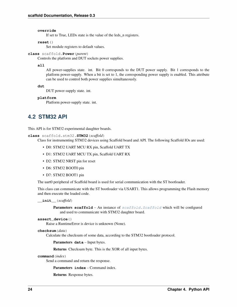
4.2 STM32 API
This API is for STM32 experimental daughter boards.
class scaffold.stm32.STM32(scaffold)Class for instrumenting STM32 devices using Scaffold board and API. The following Scaffold IOs are used:
• D0: STM32 UART MCU RX pin, Scaffold UART TX
• D1: STM32 UART MCU TX pin, Scaffold UART RX
• D2: STM32 NRST pin for reset
• D6: STM32 BOOT0 pin
• D7: STM32 BOOT1 pin
The uart0 peripheral of Scaffold board is used for serial communication with the ST bootloader.
This class can communicate with the ST bootloader via USART1. This allows programming the Flash memoryand then execute the loaded code.
__init__(scaffold)
Parameters scaffold – An instance of scaffold.Scaffold which will be configuredand used to communicate with STM32 daughter board.
assert_device()Raise a RuntimeError is device is unknown (None).
checksum(data)Calculate the checksum of some data, according to the STM32 bootloader protocol.
Parameters data – Input bytes.
Returns Checksum byte. This is the XOR of all input bytes.
command(index)Send a command and return the response.
Parameters index – Command index.
Returns Response bytes.
24 Chapter 4. Python API
scaffold Documentation, Release 0.3
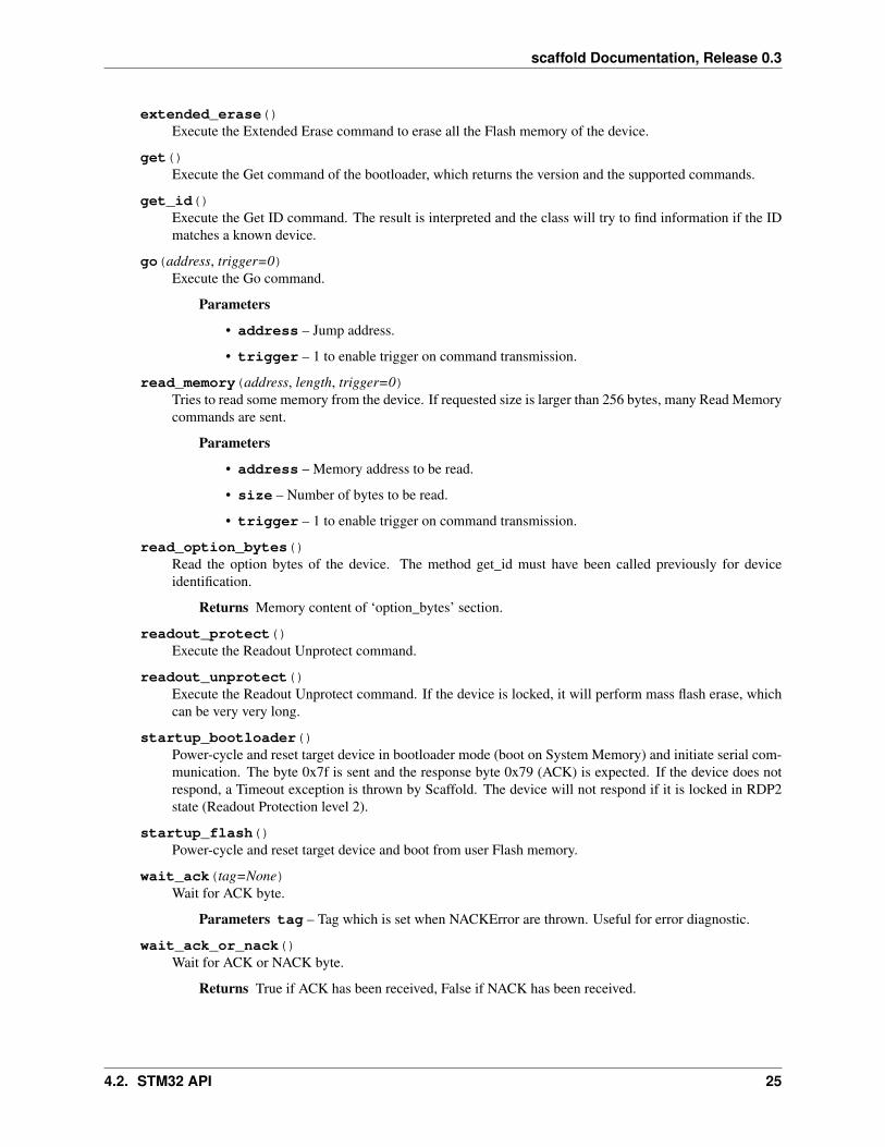
extended_erase()Execute the Extended Erase command to erase all the Flash memory of the device.
get()Execute the Get command of the bootloader, which returns the version and the supported commands.
get_id()Execute the Get ID command. The result is interpreted and the class will try to find information if the IDmatches a known device.
go(address, trigger=0)Execute the Go command.
Parameters
• address – Jump address.
• trigger – 1 to enable trigger on command transmission.
read_memory(address, length, trigger=0)Tries to read some memory from the device. If requested size is larger than 256 bytes, many Read Memorycommands are sent.
Parameters
• address – Memory address to be read.
• size – Number of bytes to be read.
• trigger – 1 to enable trigger on command transmission.
read_option_bytes()Read the option bytes of the device. The method get_id must have been called previously for deviceidentification.
Returns Memory content of ‘option_bytes’ section.
readout_protect()Execute the Readout Unprotect command.
readout_unprotect()Execute the Readout Unprotect command. If the device is locked, it will perform mass flash erase, whichcan be very very long.
startup_bootloader()Power-cycle and reset target device in bootloader mode (boot on System Memory) and initiate serial com-munication. The byte 0x7f is sent and the response byte 0x79 (ACK) is expected. If the device does notrespond, a Timeout exception is thrown by Scaffold. The device will not respond if it is locked in RDP2state (Readout Protection level 2).
startup_flash()Power-cycle and reset target device and boot from user Flash memory.
wait_ack(tag=None)Wait for ACK byte.
Parameters tag – Tag which is set when NACKError are thrown. Useful for error diagnostic.
wait_ack_or_nack()Wait for ACK or NACK byte.
Returns True if ACK has been received, False if NACK has been received.
4.2. STM32 API 25

scaffold Documentation, Release 0.3
write_memory(address, data, trigger=0)Write data to device memory. If target address is Flash memory, this function DOES NOT erase Flashmemory prior to writing. If data size is larger than 256 bytes, many Write Memory commands are sent.
Parameters
• address – Address.
• data – Data to be written. bytes or bytearray.
• trigger – 1 to enable trigger on each command transmission.
4.3 ISO7816 API
This API provides support for ISO7816 support with Scaffold.
class scaffold.iso7816.Smartcard(scaffold)Class for smartcard testing with Scaffold board and API. The following IOs are used:
• D0: ISO7816 IO
• D1: ISO7816 nRST
• D2: ISO7816 CLK
• D3: Socket card contactor sense
scaffold.Scaffold class has ISO7816 peripheral support, but it is very limited. This class adds fullsupport to ISO7816 by managing ATR, convention convertion, etc.
Variables
• atr (bytes) – ATR received from card after reset.
• convention (Convention) – Communication convention between card and terminal.Updated when first byte TS of ATR is received.
• protocols (set) – Communication protocols found in ATR. This set contains integers,for instance 0 if T=0 is supported, 1 if T=1 is supported. . .
__init__(scaffold)Configure a Scaffold board for use with smartcards. :param scaffold: scaffold.Scaffold instance.
apdu(the_apdu, trigger=”)Send an APDU to the smartcard and retrieve the response.
Parameters
• the_apdu (bytes or str) – APDU to be sent. str hexadecimal strings are allowed,but use should consider using the apdu_str() method instead.
• trigger (str) – If ‘a’ is in this string, trigger is raised after ISO-7816 header is sent,and cleared when the following response byte arrives. If ‘b’ is in this string, trigger israised after data field has been transmitted, and cleared when the next response byte isreceived.
Raises ValueError – if APDU data is invalid.
Return bytes Response data, with status word.
apdu_str(the_apdu)Same as apdu() function, with str argument and return type for convenience.
Parameters the_apdu (str) – APDU to be sent, as an hexadecimal string.
26 Chapter 4. Python API

scaffold Documentation, Release 0.3
Return str Response from the card, as a lowercase hexadecimal string without spaces.
find_info()Parse the smartcard ATR list database available at http://ludovic.rousseau.free.fr/softwares/pcsc-tools/smartcard_list.txt and try to match the current ATR to retrieve more info about the card.
The database file cannot be embedded in the library because it uses GPL and not LGPL license. On debiansystems, this file is provided in the pcsc-tools package.
Returns A list of str, where each item is an information line about the card. Return None if theATR did not match any entry in the database.
inverse_byte(byte)Inverse order and polarity of bits in a byte. Used for ISO7816 inverse convention decoding.
receive(n)Use the ISO7816 peripheral to receive bytes from the smartcard, and apply direct or inverse conventiondepending on what has been read in the ATR.
Parameters n – Number of bytes to be read.
reset()Reset the smartcard and retrieve the ATR. If the ATR is retrieved successfully, the attributes atrconvention and protocols are updated.
Returns ATR from the card.
Raises ProtocolError – if the ATR is not valid.
class scaffold.iso7816.ConventionPossible ISO7816 communication convention. This is given by the first byte of the ATR returned by the card.
DIRECT = 59
INVERSE = 63
class scaffold.iso7816.ProtocolError(message)Exception raised when a protocol error between the terminal and the smartcard occurs.
4.3. ISO7816 API 27

scaffold Documentation, Release 0.3
28 Chapter 4. Python API
CHAPTER 5
Architecture
The following documentation describes in details the architecture of Scaffold. The targeted audience is the devel-oper who wish fixing bugs in the architecture or extend its functionalities. Reading this documentation may helpunderstanding what’s under the hood.
5.1 Communication protocol
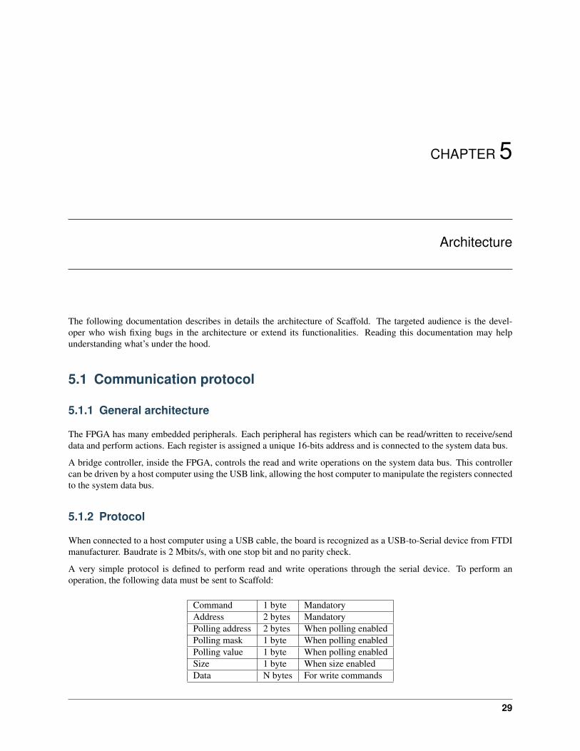
5.1.1 General architecture
The FPGA has many embedded peripherals. Each peripheral has registers which can be read/written to receive/senddata and perform actions. Each register is assigned a unique 16-bits address and is connected to the system data bus.
A bridge controller, inside the FPGA, controls the read and write operations on the system data bus. This controllercan be driven by a host computer using the USB link, allowing the host computer to manipulate the registers connectedto the system data bus.
5.1.2 Protocol
When connected to a host computer using a USB cable, the board is recognized as a USB-to-Serial device from FTDImanufacturer. Baudrate is 2 Mbits/s, with one stop bit and no parity check.
A very simple protocol is defined to perform read and write operations through the serial device. To perform anoperation, the following data must be sent to Scaffold:
Command 1 byte MandatoryAddress 2 bytes MandatoryPolling address 2 bytes When polling enabledPolling mask 1 byte When polling enabledPolling value 1 byte When polling enabledSize 1 byte When size enabledData N bytes For write commands
29

scaffold Documentation, Release 0.3
Bit 0 of command byte indicates if this is a read (0) or write (1) command. Bit 1 indicates if size parameter is present(1 to enable size). Bit 2 indicates if polling is requested for this command (1 to enable polling). All other bits must beset to zero, otherwise the command is considered invalid and Scaffold will enter error mode.
For write and read commands, a response is transmitted by the Scaffold board. This response starts by the data bytes(for register read commands) and terminates with a status byte. The status byte shall be equal to the size of theprocessed data. If a command times out during polling, the returned status byte will be lower than the size of the data.
5.1.3 Register polling
Read or write operations on registers can be conditioned to a given register expected state. When polling is enabled,each read or write operation is performed when the monitored register reaches a given value for some chosen bits.Polling is enabled when bit 2 of command byte is 1. Read or write operation is performed when (Register andMask) = (Value and Mask).
Polling can be used for flow control when using a peripheral to process multiple bytes. For instance, when using a SPIperipheral, polling can be used to wait for incoming bytes.
The polled register can be different from the read or written register (two different addresses can be passed in thecommand parameters: address and polling address).
5.1.4 Polling timeout
Optionally, a timeout can be configured for polling operations. This is particularly useful if receiving bytes from aperipheral is not guaranteed. When the polling times out in a read operation, the remaining expected bytes are sent bythe board as zero. When the polling times out in a write operation, the remaining bytes sent to the board are discardedby the bus bridge. The returned acknowledge byte indicates the number of successfully processed bytes and will belower than the requested size in the command.
The timeout delay can be configured with a special command:
Command 0x08 1 byte MandatoryPolling delay value 4 bytes MSB first
No response is expected after this command. The new delay value will be applied for all the following commands. Ifthe delay is set to zero, then the timeout is disabled (which is the default).
5.2 FPGA bus
The internal global bus connects all the peripherals together. This bus is controlled by the serial bridge which isconnected to the host computer with the USB link. The bus can perform only two simple operations:
• Read a byte from a register,
• Write a byte to a register.
The bus works using many signals:
• 16-bits address: bus_address,
• Write assertion signal: bus_write
• 8-bits write data: bus_write_data,
• Read assertion signal: bus_read
30 Chapter 5. Architecture

scaffold Documentation, Release 0.3
• 8-bits read data: bus_read_data
Using different data wires for read and write operations makes conflicts between modules impossible. Also, someFPGA devices may not allow internal bidirectional wires.
All the signals of the bus are synchronized to the system clock, on rising edges.
5.2.1 Register read cycle
clock
bus_address address
bus_read
bus_read_data data
bus_write
bus_write_data
5.2.2 Register write cycle
clock
bus_address address
bus_read
bus_read_data
bus_write
bus_write_data data
5.3 FPGA bus bridge
The bus bridge allows reading and writing bytes on the internal FPGA bus using commands sent in serial. Thisbridge is implemented in VHDL using a Finite State Machine. The state machine manages the commands parsing andexecution.
The state machine has a lot of states and is a bit complex. However, the parsing and execution of a command is fasterthan the time required to receive an incoming new command - making it hard to saturate the commands queue. Theonly cases a command queue can be overflowed is when using polling commands - in such cases the application maywait for the response before sending further commands.
5.3. FPGA bus bridge 31

scaffold Documentation, Release 0.3
Overflowing the commands queue will usually lead to entering the error state as bytes will be discarded, resulting indata bytes being interpreted as invalid command codes. When in error state, the error LED on the board is lit. Theonly way to recover from the error state is pressing the reset button.
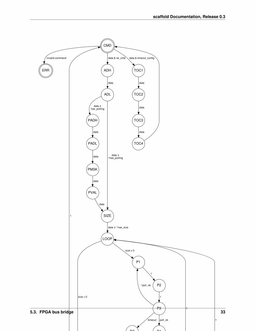
5.3.1 State machine
The following graph is the bus bridge finite state machine implemented in the FPGA. This document is an help forunderstanding FPGA internals.
32 Chapter 5. Architecture
scaffold Documentation, Release 0.3
CMD
ERR
invalid command
ADH
data & rw_cmd
TOC1
data & timeout_config
ADL
data
PADH
data ∧ has_polling
SIZE
data ∧ ! has_polling
PADL
data
LOOP
data ∨ ! has_size
PMSK
data
PVAL
data
data
P1
size ≠ 0
WAIT
size = 0
RD
WAIT
1
SEND
ready
1
VAL
WR
data
1
P2
1
P3
1
! poll_ok
P4
poll_ok
TO
timeout
read_command write_command
SEND
ready
1
TOC2
data
TOC3
data
TOC4
data
size = 0
WAIT
read_command
POP
write_command
SEND
ready
1
data
5.3. FPGA bus bridge 33

scaffold Documentation, Release 0.3
Details on states:
• CMD: Idle state, awaiting for command byte.
• ADH: Awaiting for read/write address high nibble.
• ADL: Awaiting for read/write address low nibble.
• PADH: Awaiting for polling address high nibble.
• PADL: Awaiting for polling address low nibble.
• PMSK: Awaiting for polling mask.
• PVAL: Awaiting for polling value.
• SIZE: Read/write size fetch. If the command does not require size parameter, use 1. Otherwise, wait and storenext byte received on UART.
• LOOP: Preload polling address on the bus for P1 and P2 states. Return to initial state if all bytes have been reador written.
• WAIT: Wait for UART to be ready to transmit a byte. This also acts as a delay cycle required for data bus to beavailable (due to pipelining).
• SEND: Send result byte on UART (command acknowledge or register value).
• P1: First polling state. Assert bus read signal. Due to pipelining, the data read from the bus is available to therest of the logic at P2.
• P2: Second polling state. Used for pipelining (registers the data read from the bus).
• P3: Polling test. If polling value matches, leave polling by going to P4. Otherwise, return to P1 for a newpolling read cycle.
• P4: End of polling. Load register address on the bus.
• RD: Register read cycle.
• VAL: Read from UART the byte to be written in register.
• WR: Register write cycle.
• TO: Timeout state. Loops until all unprocessed bytes have been discarded (write operation) or returned as zeros(read operation).
• POP: Cycle used to discard a byte from the input FIFO during a write operation which has timed out.
Details on transition conditions:
• 1: Unconditionally pass to the next state at the next clock cycle.
• data: True when the UART FIFO has a byte available.
• size: Number of remaining bytes to be read or written.
• ready: True when the UART of the bus bridge is ready to transmit a byte.
• read_command: True when the fetched command byte corresponds to a bus read cycle command.
• write_command: True when the fetched command byte corresponds to a bus write cycle command.
5.3.2 Polling timeout configuration
A special command bit allows reconfiguring the polling timeout delay. The delay parameter is stored in an internal 32bits register and encodes a number of clock cycles to wait during polling state (1 unit equals to 3 clock cycles). When
34 Chapter 5. Architecture

scaffold Documentation, Release 0.3
this register is set to 0, the timeout is disabled. Note that disabling the timeout is not recommended since the FSMmay stuck in a polling operation forever or until general reset.
The maximum possible timeout duration is approximately 128 seconds.
5.4 Output module
The available I/Os of the scaffold board can be internally connected to any module output. The “right matrix” controlswhich module output signals are connected to which I/Os. Each I/O has a register storing its multiplexer selecting thesource signal.
5.4.1 Multiplexers selection table
Index Signal name0 z1 02 13 /power/dut_trigger4 /power/platform_trigger5 /uart0/tx6 /uart0/trigger7 /uart1/tx8 /uart1/trigger9 /iso7816/io_out10 /iso7816/clk11 /iso7816/trigger12 /pgen0/out13 /pgen1/out14 /pgen2/out15 /pgen3/out
5.4. Output module 35

scaffold Documentation, Release 0.3
36 Chapter 5. Architecture
CHAPTER 6
Building and flashing the FPGA bitstream
Advanced users may want to modify the architecture of the FPGA of Scaffold to support more peripherals, implementnew features or even fix bugs. This section briefly describe how to build the FPGA bitstream with Intel (Altera) tools,and flash the board.
6.1 Prerequisites
Quartus II software from Intel (Altera) must be used to build the FPGA bitstream. The version of Quartus must havesupport for Cyclone IV devices; version 14.1 can be used. Although Quartus is a proprietary tool, the free QuartusWeb Edition can be used and shall not require any license. Quartus can run on linux and Windows (but we did not givea try on Windows).
For flashing the FPGA, a programmer supporting Active Serial mode must be used. Altera USB Blaster is a good one.
6.2 Building the bitstream
Under Quartus software, load the fpga-arch/scaffold.qpf project file with the File > Open Project menu.Build the design with Start context-menu of Compile Design task as highlighted below.
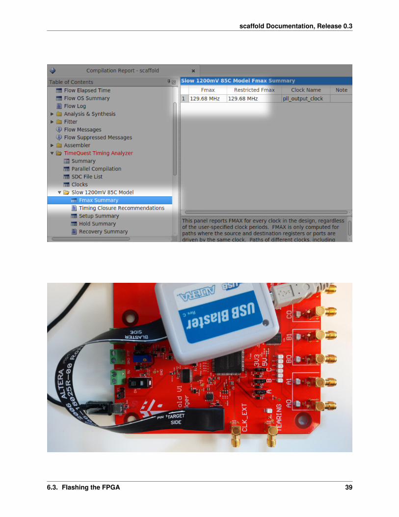
Hopefully the compilation should succeed. If you modified the original design, we recommand you to check in thecompilation report that the max frequency of the system clock of the compiled design is at least 110 MHz (100 MHzplus some security margin). If this constraint is not respected, then your design may not work properly and need to beoptimized.
6.3 Flashing the FPGA
Power-on the board and connect the programmer as shown below:
In Quartus, open the programmer window with the Tools > Programmer menu.
37

scaffold Documentation, Release 0.3
38 Chapter 6. Building and flashing the FPGA bitstream
scaffold Documentation, Release 0.3
6.3. Flashing the FPGA 39

scaffold Documentation, Release 0.3
• Setup your programmer with the Hardware Setup button.
• Switch to Active Serial Programming mode.
• Click on Add File. . . and select the file confware.pof. The setup shall represent an EPCS16 device, whichis the on-board Flash memory storing the bitstream and read by the FPGA when powering-up Scaffold.
• Check the Program/Configure and Verify boxes.
• Click on the Start button.
Remove the programmer cable to test your new design!
40 Chapter 6. Building and flashing the FPGA bitstream

CHAPTER 7
Indices and tables
• genindex
• modindex
• search
41

scaffold Documentation, Release 0.3
42 Chapter 7. Indices and tables
Python Module Index
sscaffold, 19scaffold.iso7816, 26scaffold.stm32, 24
43

scaffold Documentation, Release 0.3
44 Python Module Index
Index
Symbols__init__() (scaffold.Scaffold method), 19__init__() (scaffold.Signal method), 20__init__() (scaffold.iso7816.Smartcard method), 26__init__() (scaffold.stm32.STM32 method), 24__lshift__() (scaffold.Signal method), 20__str__() (scaffold.Signal method), 20
Aall (scaffold.Power attribute), 24apdu() (scaffold.iso7816.Smartcard method), 26apdu_str() (scaffold.iso7816.Smartcard method), 26assert_device() (scaffold.stm32.STM32 method),
24
Bbaudrate (scaffold.UART attribute), 21brightness (scaffold.LEDs attribute), 23
Cchecksum() (scaffold.stm32.STM32 method), 24clear_event() (scaffold.IO method), 20clock_frequency (scaffold.ISO7816 attribute), 21clock_stretching (scaffold.I2C attribute), 22command() (scaffold.stm32.STM32 method), 24Convention (class in scaffold.iso7816), 27count (scaffold.PulseGenerator attribute), 23
Ddelay (scaffold.PulseGenerator attribute), 23dir (scaffold.GroupIO attribute), 21DIRECT (scaffold.iso7816.Convention attribute), 27disabled (scaffold.LEDs attribute), 23dut (scaffold.Power attribute), 24
Eempty (scaffold.ISO7816 attribute), 21etu (scaffold.ISO7816 attribute), 21event (scaffold.IO attribute), 20
extended_erase() (scaffold.stm32.STM32 method),24
Ffind_info() (scaffold.iso7816.Smartcard method),
27fire() (scaffold.PulseGenerator method), 23flush() (scaffold.I2C method), 22flush() (scaffold.ISO7816 method), 22flush() (scaffold.UART method), 21frequency (scaffold.I2C attribute), 22
Gget() (scaffold.stm32.STM32 method), 25get_id() (scaffold.stm32.STM32 method), 25go() (scaffold.stm32.STM32 method), 25GroupIO (class in scaffold), 20
II2C (class in scaffold), 22interval (scaffold.PulseGenerator attribute), 23INVERSE (scaffold.iso7816.Convention attribute), 27inverse_byte() (scaffold.iso7816.Smartcard
method), 27IO (class in scaffold), 20ISO7816 (class in scaffold), 21
LLEDs (class in scaffold), 23
Mmode (scaffold.IO attribute), 20
Nname (scaffold.Signal attribute), 20
Ooverride (scaffold.LEDs attribute), 23
45

scaffold Documentation, Release 0.3
Pparent (scaffold.Signal attribute), 20parity_mode (scaffold.ISO7816 attribute), 22path (scaffold.Signal attribute), 20platform (scaffold.Power attribute), 24Power (class in scaffold), 24ProtocolError (class in scaffold.iso7816), 27PulseGenerator (class in scaffold), 23
Rraw_transaction() (scaffold.I2C method), 22read() (scaffold.I2C method), 23read_memory() (scaffold.stm32.STM32 method), 25read_option_bytes() (scaffold.stm32.STM32
method), 25readout_protect() (scaffold.stm32.STM32
method), 25readout_unprotect() (scaffold.stm32.STM32
method), 25receive() (scaffold.ISO7816 method), 22receive() (scaffold.iso7816.Smartcard method), 27receive() (scaffold.UART method), 21reset() (scaffold.iso7816.Smartcard method), 27reset() (scaffold.LEDs method), 24reset() (scaffold.UART method), 21reset_config() (scaffold.I2C method), 23reset_config() (scaffold.ISO7816 method), 22
SScaffold (class in scaffold), 19scaffold (module), 19scaffold.iso7816 (module), 26scaffold.stm32 (module), 24Signal (class in scaffold), 19Smartcard (class in scaffold.iso7816), 26startup_bootloader() (scaffold.stm32.STM32
method), 25startup_flash() (scaffold.stm32.STM32 method),
25STM32 (class in scaffold.stm32), 24
Ttransmit() (scaffold.ISO7816 method), 22transmit() (scaffold.UART method), 21trigger_long (scaffold.ISO7816 attribute), 22trigger_rx (scaffold.ISO7816 attribute), 22trigger_tx (scaffold.ISO7816 attribute), 22
UUART (class in scaffold), 21
Vvalue (scaffold.IO attribute), 20
Wwait_ack() (scaffold.stm32.STM32 method), 25wait_ack_or_nack() (scaffold.stm32.STM32
method), 25width (scaffold.PulseGenerator attribute), 23write() (scaffold.I2C method), 23write_memory() (scaffold.stm32.STM32 method), 25
46 Index