relays and relay devices products and applications - hella… · hella produces more than 100...
TRANSCRIPT

RELAYS AND RELAY DEVICESPRODUCTS AND APPLICATIONS
www.hella.com

INTRODUCTION

| 32
INTRODUCTION 2A small component with a big history . . . . . . . . . . . . . . . . . . . . . . . . . . . . . . . . . . . . . . . . . . . . . . . . . . . . 4How HELLA checks and ensures quality . . . . . . . . . . . . . . . . . . . . . . . . . . . . . . . . . . . . . . . . . . . . . . . . . . 7
ELECTROMECHANICAL RELAYS 8Explanation and uses . . . . . . . . . . . . . . . . . . . . . . . . . . . . . . . . . . . . . . . . . . . . . . . . . . . . . . . . . . . . . . . . . . 8Relay types . . . . . . . . . . . . . . . . . . . . . . . . . . . . . . . . . . . . . . . . . . . . . . . . . . . . . . . . . . . . . . . . . . . . . . . . . . 12Mini relay 12 V – make contact with holder . . . . . . . . . . . . . . . . . . . . . . . . . . . . . . . . . . . . . . . . . . . . . . 13Mini relay 12 V, make contact without holder . . . . . . . . . . . . . . . . . . . . . . . . . . . . . . . . . . . . . . . . . . . . . 14Mini relay 12 V, change-over contact with holder . . . . . . . . . . . . . . . . . . . . . . . . . . . . . . . . . . . . . . . . . . 15Mini relay 12 V, make contact without holder . . . . . . . . . . . . . . . . . . . . . . . . . . . . . . . . . . . . . . . . . . . . . 16Mini relay 24 V – make contact with holder . . . . . . . . . . . . . . . . . . . . . . . . . . . . . . . . . . . . . . . . . . . . . . 17Mini relay 24 V, make contact without holder . . . . . . . . . . . . . . . . . . . . . . . . . . . . . . . . . . . . . . . . . . . . . 18Mini relay 24 V, change-over contact with holder . . . . . . . . . . . . . . . . . . . . . . . . . . . . . . . . . . . . . . . . . . 19Mini relay 24 V, make contact without holder . . . . . . . . . . . . . . . . . . . . . . . . . . . . . . . . . . . . . . . . . . . . . 20
MICRO RELAY 22Micro relay 12V, make contact without holder / change-over contact without holder . . . . . . . . . . 22Micro relay 24V, change-over contact without holder . . . . . . . . . . . . . . . . . . . . . . . . . . . . . . . . . . . . . . 23
HIGH�POWER RELAY 24High-power relay 12V, make contact with holder/without holder . . . . . . . . . . . . . . . . . . . . . . . . . . . 24High-power relay 24V, make contact with holder/without holder . . . . . . . . . . . . . . . . . . . . . . . . . . . 25
BATTERY DISCONNECT RELAY/SOLID STATE RELAY 26Battery disconnect relay and solid state relay 12V, make contact . . . . . . . . . . . . . . . . . . . . . . . . . . . 26Summary of battery disconnect and solid state relays . . . . . . . . . . . . . . . . . . . . . . . . . . . . . . . . . . . . . 27
TECHNICAL DATA 28Technical data of the relays – Overview . . . . . . . . . . . . . . . . . . . . . . . . . . . . . . . . . . . . . . . . . . . . . . . . . . 28Climatic and mechanical tests . . . . . . . . . . . . . . . . . . . . . . . . . . . . . . . . . . . . . . . . . . . . . . . . . . . . . . . . . . 30
FLASHER UNITS 32Explanation and uses . . . . . . . . . . . . . . . . . . . . . . . . . . . . . . . . . . . . . . . . . . . . . . . . . . . . . . . . . . . . . . . . . 32Test circuits . . . . . . . . . . . . . . . . . . . . . . . . . . . . . . . . . . . . . . . . . . . . . . . . . . . . . . . . . . . . . . . . . . . . . . . . . . 36Flasher unit 6V, 4-pole and 12V, 3-pole . . . . . . . . . . . . . . . . . . . . . . . . . . . . . . . . . . . . . . . . . . . . . . . . . . 38Flasher unit 12V, 3-pole . . . . . . . . . . . . . . . . . . . . . . . . . . . . . . . . . . . . . . . . . . . . . . . . . . . . . . . . . . . . . . . 39Flasher unit 12V, 4-pole . . . . . . . . . . . . . . . . . . . . . . . . . . . . . . . . . . . . . . . . . . . . . . . . . . . . . . . . . . . . . . . 40Flasher unit 12V, 5-pole/6-pole . . . . . . . . . . . . . . . . . . . . . . . . . . . . . . . . . . . . . . . . . . . . . . . . . . . . . . . . 41Flasher unit 12V, 6-pole/7-pole . . . . . . . . . . . . . . . . . . . . . . . . . . . . . . . . . . . . . . . . . . . . . . . . . . . . . . . . 42Flasher unit 24V, 3-pole/4-pole . . . . . . . . . . . . . . . . . . . . . . . . . . . . . . . . . . . . . . . . . . . . . . . . . . . . . . . . 43Flasher unit 24V, 4-pole/5-pole . . . . . . . . . . . . . . . . . . . . . . . . . . . . . . . . . . . . . . . . . . . . . . . . . . . . . . . . 44Flasher unit 24V, 6-pole/7-pole . . . . . . . . . . . . . . . . . . . . . . . . . . . . . . . . . . . . . . . . . . . . . . . . . . . . . . . . 45Flasher unit 24 V, 11-pole and 12/24 V, 6-pole . . . . . . . . . . . . . . . . . . . . . . . . . . . . . . . . . . . . . . . . . . . 46LED fl asher unit 12/24V, 3-pole; 12V, 4-pole/5-pole and 24V, 4-pole . . . . . . . . . . . . . . . . . . . . . . . . 47Overview of fl asher unit technical data . . . . . . . . . . . . . . . . . . . . . . . . . . . . . . . . . . . . . . . . . . . . . . . . . . 48Legal regulations for fl asher units . . . . . . . . . . . . . . . . . . . . . . . . . . . . . . . . . . . . . . . . . . . . . . . . . . . . . . 48LED indicators and failure control from HELLA . . . . . . . . . . . . . . . . . . . . . . . . . . . . . . . . . . . . . . . . . . . 49The right solution for your vehicle electronics . . . . . . . . . . . . . . . . . . . . . . . . . . . . . . . . . . . . . . . . . . . . 50
WASH/WIPE INTERVAL CONTROL UNITS 52Explanation and uses . . . . . . . . . . . . . . . . . . . . . . . . . . . . . . . . . . . . . . . . . . . . . . . . . . . . . . . . . . . . . . . . . 52Wash/wipe interval control units 12V . . . . . . . . . . . . . . . . . . . . . . . . . . . . . . . . . . . . . . . . . . . . . . . . . . . 54Wash/wipe interval control units 24V . . . . . . . . . . . . . . . . . . . . . . . . . . . . . . . . . . . . . . . . . . . . . . . . . . . 55Headlight cleaning system 12V/24V . . . . . . . . . . . . . . . . . . . . . . . . . . . . . . . . . . . . . . . . . . . . . . . . . . . . . 56
CLOCK RELAYS 58Explanation and uses . . . . . . . . . . . . . . . . . . . . . . . . . . . . . . . . . . . . . . . . . . . . . . . . . . . . . . . . . . . . . . . . . 58Clock relays 12V . . . . . . . . . . . . . . . . . . . . . . . . . . . . . . . . . . . . . . . . . . . . . . . . . . . . . . . . . . . . . . . . . . . . . . 60Clock relays 24V . . . . . . . . . . . . . . . . . . . . . . . . . . . . . . . . . . . . . . . . . . . . . . . . . . . . . . . . . . . . . . . . . . . . . . 61
ACCESSORIES 62Overview . . . . . . . . . . . . . . . . . . . . . . . . . . . . . . . . . . . . . . . . . . . . . . . . . . . . . . . . . . . . . . . . . . . . . . . . . . . . 62
SWITCHING AND PLUG MATRICES 64Circuit diagrams – electromechanical relays . . . . . . . . . . . . . . . . . . . . . . . . . . . . . . . . . . . . . . . . . . . . . 64Pin diagrams – electromechanical relays . . . . . . . . . . . . . . . . . . . . . . . . . . . . . . . . . . . . . . . . . . . . . . . . 65Pin diagrams – fl asher units . . . . . . . . . . . . . . . . . . . . . . . . . . . . . . . . . . . . . . . . . . . . . . . . . . . . . . . . . . . 66Pin diagrams – wash/wipe interval control units . . . . . . . . . . . . . . . . . . . . . . . . . . . . . . . . . . . . . . . . . 67Pin diagrams – clock relays . . . . . . . . . . . . . . . . . . . . . . . . . . . . . . . . . . . . . . . . . . . . . . . . . . . . . . . . . . . . 67Pin diagrams – control units for headlight cleaning systems . . . . . . . . . . . . . . . . . . . . . . . . . . . . . . . 67
HELLA ROCKER SWITCHES 68The new HELLA switch confi gurator . . . . . . . . . . . . . . . . . . . . . . . . . . . . . . . . . . . . . . . . . . . . . . . . . . . . 68Rocker switch, 3100 series. . . . . . . . . . . . . . . . . . . . . . . . . . . . . . . . . . . . . . . . . . . . . . . . . . . . . . . . . . . . . 70Switch functions . . . . . . . . . . . . . . . . . . . . . . . . . . . . . . . . . . . . . . . . . . . . . . . . . . . . . . . . . . . . . . . . . . . . . . 71

INTRODUCTION
A small component with a big history
From the telegraph to automotive engineering
� The relay owes its name to former times when mail was still carried by horse. At what were known as relay stations, post riders could swap their horses for rested ones. Today, we call an electromagnetic, remotely operated switch a relay.
� The American physician Joseph Henry invented the electric relay in 1835. The pioneer in communications engineering used it to send messages from his laboratory to his home. Relays were first used on a larger scale in 1837, as signal amplifiers for Samuel Morse’s recording telegraphs. They would later make possible the widespread use of telephones and became a cornerstone of safety in railway engineering. In 1941, Konrad Zuse utilised 2,000 relays in his legendary Z3, the first digital computer. HELLA produced its first automotive relay in 1960.
� As electronics matured in the 20th century, the age of the relay was often seen as over; nevertheless, they retain a place in specific applications. The automotive industry, for example, needs relays, since relay functions cannot always be replaced by control units. Only relays make galvanic isolation possible between input and output. Semi-conductors cannot manage this at the moment. The cost advantage relays have over electronic solutions is also unbeatable.
� Relays are used in automotive engineering to switch high currents. The engine control unit, for example, is switched by a relay. Because relays are robust and not particularly susceptible to failure, they can be installed near electric devices. They require only low control currents, making small line cross-sections sufficient. The switching and amplifier function of a relay could only be achieved with a lot more effort and a lot less reliability using more “modern” electronics. Another benefit of the relay is that it is quick and easy to replace. These positive characteristics are the reason why relays are still in use. And they ensure that, in the future, relays will still be at home in many vehicles.
Relays have been used to remotely control circuits for over 180 years. The technology has proven its reliability millions of times and is today still the first choice for many applications, such as in automotive engineering.
Quality relays from HELLA – versatile and reliable
� Manufacturing expertise: HELLA produces more than 100 million units per year at its own facilities – thanks to optimised production at an attractive price and with one of the lowest failure rates in the entire industry.
� Flexibility: Large volumes are produced in a fully automated process, small volumes with semi-automation. This means we are in a position to change over quickly to semi-automatic production. HELLA is able to respond promptly to customer requirementsand create new variants in addition to its existing product range at short notice.
� OEM customers: HELLA develops and produces relays for AGCO, Claas, Daimler AG, Ford, VW, GM, JCB, Opel/Vauxhall, Nissan, John Deere, Chrysler, Jaguar/Land Rover and others. Many of our customer relationships have existed for decades.
� Production locations: Berlin (Germany); Flora, Illinois (USA); Xiamen (China).

| 54
1951 First hot-wire flasher unit
1960 A-relay with metal housing.Mechanical threshold voltage controller for windshield wipers
1965 E-relay: the first fully electronic flasher unit
1968 L-relay: the first modular system
1969 Wipe/wash interval control unit
1970 K-relay: current controlled relay for direction indicator lampsBi-stable relay for switching between low and high beam
1972 Q-relay with plastic base plate, also available with built-in fuse
1973 V-relay: PCB relay for automatic placement
1976 S1-relay: replacement for Q-relay. Can be produced fully automatically, also available with built-in fuse
1978 H-relay: high-power relay for different motor loads
1982 Sounding relay for controlling direction indicator lamps
1989 Round connector relay: specially produced for Daimler AG, with plastic housing
1994 Micro relay: designed for fully automated production
1998 Mini solid state relay
2003 Bi-stable battery disconnect relay with flexible attachment system
2005 Micro relay: high-current and bi-stable version
2006 Intelligent flasher units for active LED flashers with current pulse evaluation in acc. with ISO 13207-1
2008 Flasher unit with microprocessor technology
2012 New and refined relay products with lower power consumption to help reduce CO2 emissions

INTRODUCTION

| 76
How HELLA checks and ensures quality
1) Load curve, 20 A resistive 10 A 500 ms
1) Load curve, 3 x high beam 10 A 500 ms
Time (minutes)
Tem
pera
ture
(°C)
Rela
tive
hum
idity
(%)
■ Design life tests:The relays are switched on/off in cycles on fully automated test racks. Original loads or simulated resistive, inductive, capacitive or combined loads whose current characteristics are recorded as the original loads are connected. In addition, the relays can be subjected to different ambient temperature ranges or temperature profiles. The test is continuously documented.
■ Electrical parameters:Within the context of product release, starting voltage, dropout voltage, contact voltage drop, coil resistance and insulation resistance are tested, for example. Accompanying the manufacturing process, the electrical parameters are recorded at the end of the production process by end-of-line testers. These can be evaluated statistically. One important factor for guaranteeing the consistent high quality of the relays produced.
■ Environmental and mechanical tests:Every relay has to pass tests such as the alternating temperature test, salt spray fog test, mechanical shock test or drop test and the vibration test within the context of the product release process. These tests are carried out using HELLA equipment.
■ Analytical tests:Here, the materials used and the different connecting processes such as soldering and welding are tested. The tests are carried out randomly during incoming goods testing and following production.
■ Certificates:HELLA has been certified in a range of relevant areas e.g. DIN EN ISO 9001:2008, ISO / TS 16949:2009, ISO 14001. HELLA relays also comply with the ROHS (2002/95/EC) and REACh standards.

ELECTROMECHANICAL RELAYS
Explanation and usesKey components of an electromechanical relay
Legend
Contact plates
Armature
Pins for coil wire
Switch contacts
Coil made of Cu wire
Iron core (in the coil)
Blade terminal (load) made of E-Cu (electrolytic copper) with tin-plated surface
Blade terminal (coil) made of CuZn (brass) with tin-plated surface
Base plate
Coil body
Yoke
| 98
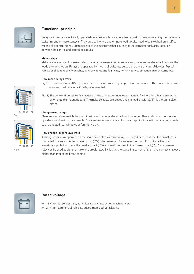
Functional principle
Relays are basically electrically operated switches which use an electromagnet to move a switching mechanism by switching one or more contacts. They are used where one or more load circuits need to be switched on or off by means of a control signal. Characteristic of the electromechanical relay is the complete (galvanic) isolation between the control and controlled circuits.
Make relaysMake relays are used to close an electric circuit between a power source and one or more electrical loads, i.e. the loads are switched on. Relays are operated by means of switches, pulse generators or control devices. Typical vehicle applications are headlights, auxiliary lights and fog lights, horns, heaters, air conditioner systems, etc.
How make relays workFig.1) The control circuit (86/85) is inactive and the return spring keeps the armature open. The make contacts are
open and the load circuit (30/87) is interrupted.
Fig. 2) The control circuit (86/85) is active and the copper coil induces a magnetic field which pulls the armature down onto the magnetic core. The make contacts are closed and the load circuit (30/87) is therefore also closed.
Change-over relaysChange-over relays switch the load circuit over from one electrical load to another. These relays can be operated by a dashboard switch, for example. Change-over relays are used for switch applications with two stages/speeds such as heated rear windows or fan motors etc.
How change-over relays workA change-over relay operates on the same principle as a make relay. The only difference is that the armature is connected to a second (alternative) output (87a) when released. As soon as the control circuit is active, the armature is pulled in, opens the break contact (87a) and switches over to the make contact (87). A change-over relay can be used as either a make or a break relay. By design, the switching current of the make contact is always higher than that of the break contact.
Rated voltage
� 12 V: for passenger cars, agricultural and construction machinery etc. � 24 V: for commercial vehicles, buses, municipal vehicles etc.
Fig. 1
Fig. 2

Rated load (depending on load type)
� Resistive load:The current remains around the same from switch-on to switch-off (e.g. rear window heater).
A
Example load curve, resistive load
Example load curve, inductive load
Example load curve, capacitive/bulb load
ELECTROMECHANICAL RELAYS
� Inductive load:The inrush current increases to the rated current with a specific delay time due to the build-up of the inductor’s magnetic field and then levels off (e.g. switching on a solenoid switch). During switch-off, a voltage of up to several thousand volts is (theoretically) induced, resulting in an electric arc between the relay contacts just opened.
� Capacitive/bulb load:The inrush current of a capacitive load or a lamp can rise to ten times the rated current before leveling off to the rated current.

| 1110
Coil circuit
In order to prevent voltage spikes caused by mutual inductance when switching off the coil current, our relays are in part equipped with resistors or diodes parallel to the coil.
Contacts and connector configurations
30 Load current +, terminal 15 (input)85 Relay coil - (input)86 Relay coil + (input)87 Load current, make contact (output)87a Load current, break contact (output)

ELECTROMECHANICAL RELAYS
Relay types
Mini relaysMini relays according to ISO 7588-1, blade terminals according to ISO 8092-1. Contact arrangements: make contact, change-over contact, max. 40 A switching power (make contact), rated voltage: 12 V, 24 VAreas of application include: headlights, starters, fuel pumps, fan motors, horns and fanfares.
Micro relayMicro relays according to ISO 7588-3 (1988), blade terminals according to ISO 8092-1.Contact arrangements: make contact, change-over contact, max. 20 A switching power (make contact), rated voltage: 12 V, 24 VAreas of application include: fuel pumps, air conditioning systems, windshield washer systems, wiper motors.
High-power relayMini relay version with larger dimensions, blade terminals according to ISO 8092-1.Contact arrangement: make contact, change-over contact, max. 60 A switching power, rated voltage: 12 V, 24 VAreas of application include: battery disconnect relays, starter motors, glow plugs, ignitions, windshield heating.
Solid state relayMini semiconductor relays according to ISO 7588-1, blade terminals according to ISO 8092-1.Contact arrangement: make contact, max. 22 A switching power (make contact), rated voltage: 12 VAreas of application include: vacuum pumps for brake booster support, daytime running lights.
Battery disconnect relayBi-stable electromechanical relay with one or two coils.Contact arrangement: make contact, max. 180 A switching power, rated voltage: 12 VAreas of application include: disconnecting the vehicle electric system from the battery in the event of accidents or for maintenance, retain battery charge by switching off quiescent current
| 1312
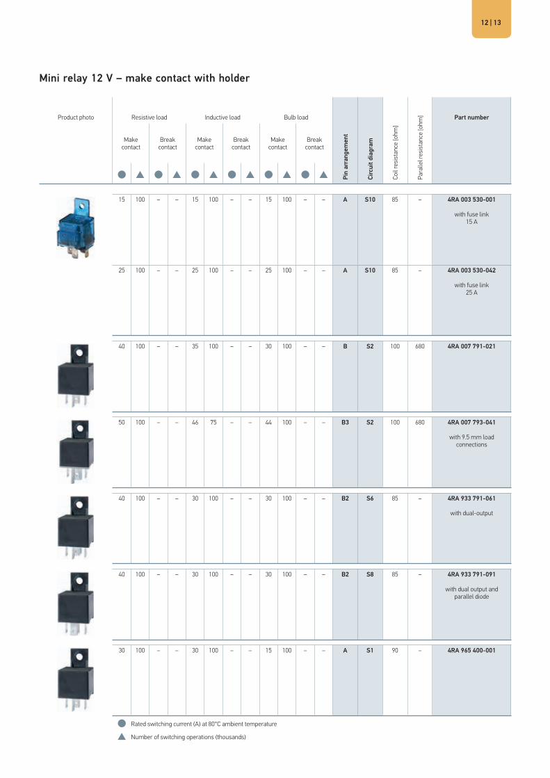
Mini relay 12 V – make contact with holder
Product photo Resistive load Inductive load Bulb load
Pin
arra
ngem
ent
Circ
uit d
iagr
am
Coil
resi
stan
ce [o
hm]
Para
llel r
esis
tanc
e [o
hm] Part number
Make contact
Break contact
Make contact
Break contact
Make contact
Break contact
● ● ● ● ● ●
15 100 – – 15 100 – – 15 100 – – A S10 85 – 4RA 003 530-001
with fuse link 15 A
25 100 – – 25 100 – – 25 100 – – A S10 85 – 4RA 003 530-042
with fuse link 25 A
40 100 – – 35 100 – – 30 100 – – B S2 100 680 4RA 007 791-021
50 100 – – 46 75 – – 44 100 – – B3 S2 100 680 4RA 007 793-041
with 9.5 mm load connections
40 100 – – 30 100 – – 30 100 – – B2 S6 85 – 4RA 933 791-061
with dual-output
40 100 – – 30 100 – – 30 100 – – B2 S8 85 – 4RA 933 791-091
with dual output and parallel diode
30 100 – – 30 100 – – 15 100 – – A S1 90 – 4RA 965 400-001
● Rated switching current (A) at 80°C ambient temperature
Number of switching operations (thousands)

MINI RELAYS
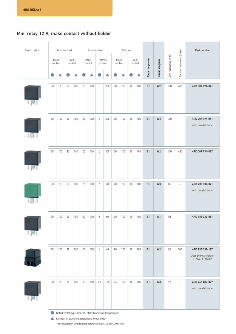
Mini relay 12 V, make contact without holder
Product photo Resistive load Inductive load Bulb load
Pin
arra
ngem
ent
Circ
uit d
iagr
am
Coil
resi
stan
ce [o
hm]
Para
llel r
esis
tanc
e [o
hm] Part number
Make contact
Break contact
Make contact
Break contact
Make contact
Break contact
● ● ● ● ● ●
40 100 – – 35 100 – – 30 100 – – B S2 100 680 4RA 007 791-011
50 100 – – 46 75 – – 44 100 – – B3 S2 100 680 4RA 007 793-031
with 9.5 mm load connections
40 100 – – 30 100 – – 30 100 – – B S1 85 – 4RA 933 332-101
40 100 – – 30 100 – – 30 100 – – B2 S6 85 – 4RA 933 332-151
with dual-output
40 100 – – 30 100 – – 30 100 – – B S2 85 560 4RA 933 332-211
40 100 – – 30 100 – – 30 100 – – B S3 85 – 4RA 933 332-221
with parallel diode
30 100 – – 30 100 – – 16 100 – – A S1 90 – 4RA 965 400-017
● Rated switching current (A) at 80°C ambient temperature
Number of switching operations (thousands)

| 1514
Mini relay 12 V, change-over contact with holder
Product photo Resistive load Inductive load Bulb load
Pin
arra
ngem
ent
Circ
uit d
iagr
am
Coil
resi
stan
ce [o
hm]
Para
llel r
esis
tanc
e [o
hm] Part number
Make contact
Break contact
Make contact
Break contact
Make contact
Break contact
● ● ● ● ● ●
30 100 20 100 20 100 5 300 30 100 10 100 B1 W2 100 680 4RD 007 794-031
30 100 20 100 20 100 6 60 20 100 10 100 B1 W1 85 – 4RD 933 332-011
30 100 20 100 20 100 6 60 20 100 10 100 B1 W2 85 560 4RD 933 332-031
Dust and waterproof, IP 6K7 / IP 6K9K*
30 100 20 100 20 100 6 60 20 100 10 100 B1 W1 85 – 4RD 933 332-041
30 100 20 100 20 100 6 60 20 100 10 100 B1 W1 85 – 4RD 933 332-237
30 100 20 100 20 100 6 60 20 100 10 100 B1 W3 85 – 4RD 933 332-277
with parallel diode
● Rated switching current (A) at 80°C ambient temperature
Number of switching operations (thousands)
* in conjunction with mating connector 8JD 745 801-001/-011
MINI RELAYS
Mini relay 12 V, make contact without holder
Product photo Resistive load Inductive load Bulb load
Pin
arra
ngem
ent
Circ
uit d
iagr
am
Coil
resi
stan
ce [o
hm]
Para
llel r
esis
tanc
e [o
hm] Part number
Make contact
Break contact
Make contact
Break contact
Make contact
Break contact
● ● ● ● ● ●
30 100 20 100 20 100 5 300 30 100 10 100 B1 W2 100 680 4RD 007 794-021
30 100 20 100 20 100 5 300 30 100 10 100 B1 W3 100 – 4RD 007 794-041
with parallel diode
30 100 20 100 20 100 5 300 30 100 10 100 B1 W2 100 680 4RD 007 794-077
30 100 20 100 20 100 6 60 20 100 10 100 B1 W3 85 – 4RD 933 332-021
with parallel diode
30 100 20 100 20 100 6 60 20 100 10 100 B1 W1 85 – 4RD 933 332-051
30 100 20 100 20 100 6 60 20 100 10 100 B1 W2 85 560 4RD 933 332-177
Dust and waterproof, IP 6K7 / IP 6K9K*
30 100 15 100 33 150 20 150 16 100 8 100 A1 W3 95 – 4RD 965 400-027
with parallel diode
● Rated switching current (A) at 80°C ambient temperature
Number of switching operations (thousands)
* in conjunction with mating connector 8JD 745 801-001/-011

| 1716
Mini relay 24 V – make contact with holder
Product photo Resistive load Inductive load Bulb load
Pin
arra
ngem
ent
Circ
uit d
iagr
am
Coil
resi
stan
ce [o
hm]
Para
llel r
esis
tanc
e [o
hm] Part number
Make contact
Break contact
Make contact
Break contact
Make contact
Break contact
● ● ● ● ● ●
15 100 – – 15 100 – – 15 100 – – A S10 315 – 4RA 003 530-051
with fuse link 15 A
20 150 – – 16 100 – – 16 135 – – B S2 305 1200 4RA 007 957-011
20 250 – – 16 100 – – 16 250 – – B2 S6 350 – 4RA 933 791-071
with dual-output
30 250 – – 16 100 – – 16 250 – – A S1 360 – 4RA 965 400-031
● Rated switching current (A) at 80°C ambient temperature
Number of switching operations (thousands)

MINI RELAYS
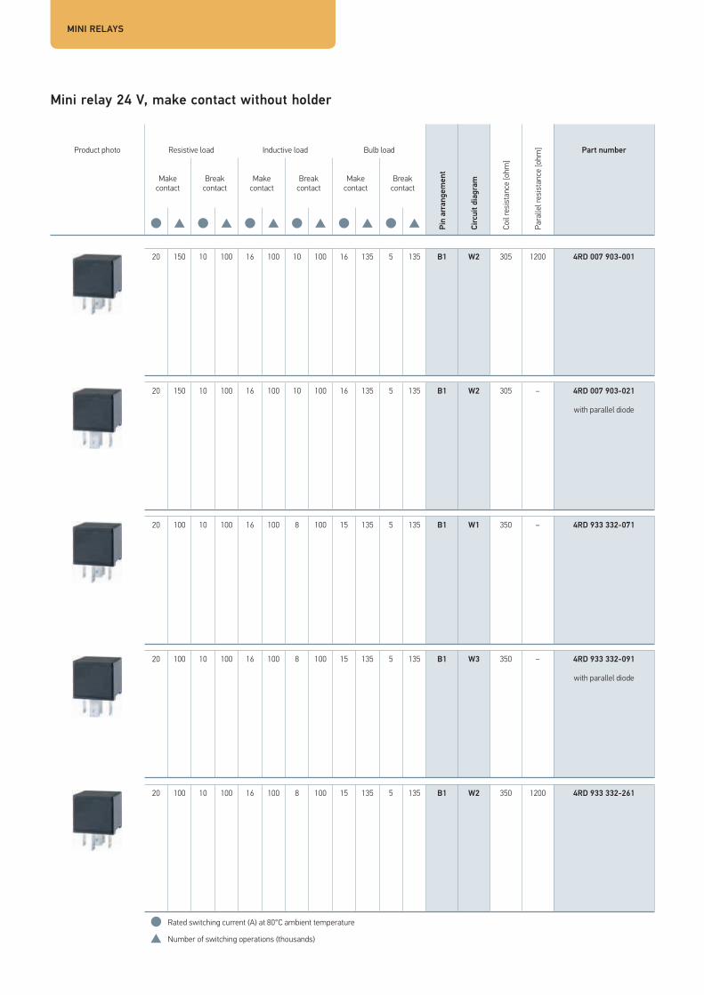
Mini relay 24 V, make contact without holder
Product photo Resistive load Inductive load Bulb load
Pin
arra
ngem
ent
Circ
uit d
iagr
am
Coil
resi
stan
ce [o
hm]
Para
llel r
esis
tanc
e [o
hm] Part number
Make contact
Break contact
Make contact
Break contact
Make contact
Break contact
● ● ● ● ● ●
20 150 – – 16 100 – – 16 135 – – B S2 305 1200 4RA 007 957-001
40 100 – – 30 100 – – 30 100 – – B3 S1 360 – 4RA 933 321-021
20 250 – – 16 100 – – 16 250 – – B S1 350 – 4RA 933 332-111
20 250 – – 16 100 – – 16 250 – – B2 S6 350 – 4RA 933 791-081
● Rated switching current (A) at 80°C ambient temperature
Number of switching operations (thousands)

| 1918
Mini relay 24 V, change-over contact with holder
Product photo Resistive load Inductive load Bulb load
Pin
arra
ngem
ent
Circ
uit d
iagr
am
Coil
resi
stan
ce [o
hm]
Para
llel r
esis
tanc
e [o
hm] Part number
Make contact
Break contact
Make contact
Break contact
Make contact
Break contact
● ● ● ● ● ●
20 150 10 100 16 100 10 100 16 135 5 135 B1 W2 305 1200 4RD 007 903-011
20 100 10 100 16 100 8 100 15 135 5 135 B1 W1 350 – 4RD 933 332-061
20 100 10 100 16 100 8 100 15 135 5 135 B1 W3 350 – 4RD 933 332-081
with parallel diode
● Rated switching current (A) at 80°C ambient temperature
Number of switching operations (thousands)
MINI RELAYS
Mini relay 24 V, make contact without holder
Product photo Resistive load Inductive load Bulb load
Pin
arra
ngem
ent
Circ
uit d
iagr
am
Coil
resi
stan
ce [o
hm]
Para
llel r
esis
tanc
e [o
hm] Part number
Make contact
Break contact
Make contact
Break contact
Make contact
Break contact
● ● ● ● ● ●
20 150 10 100 16 100 10 100 16 135 5 135 B1 W2 305 1200 4RD 007 903-001
20 150 10 100 16 100 10 100 16 135 5 135 B1 W2 305 – 4RD 007 903-021
with parallel diode
20 100 10 100 16 100 8 100 15 135 5 135 B1 W1 350 – 4RD 933 332-071
20 100 10 100 16 100 8 100 15 135 5 135 B1 W3 350 – 4RD 933 332-091
with parallel diode
20 100 10 100 16 100 8 100 15 135 5 135 B1 W2 350 1200 4RD 933 332-261
● Rated switching current (A) at 80°C ambient temperature
Number of switching operations (thousands)

| 2120

MICRO RELAY
Micro relay 12V, make contact without holder / change-over contact without holder
Product photo Resistive load Inductive load Bulb load
Pin
arra
ngem
ent
Circ
uit d
iagr
am
Coil
resi
stan
ce [o
hm]
Para
llel r
esis
tanc
e [o
hm] Part number
Make contact
Break contact
Make contact
Break contact
Make contact
Break contact
● ● ● ● ● ●
20 150 – – 15 150 – – 16 150 – – C S2 92 470 4RA 007 813-011
20 100 – – 20 100 – – 20 100 – – C3 L1 2 x 75 – 4RC 933 364-027
Bi-stable
20 150 10 150 11 100 11 100 20 100 10 100 C1 W2 92 470 4RD 007 814-011
35 100 20 100 30 100 10 100 30 100 10 100 C1 W2 140 1000 4RD 933 319-007
with locating lugs
● Rated switching current (A) at 80°C ambient temperature
Number of switching operations (thousands)

| 2322
Micro relay 24V, change-over contact without holder
Product photo Resistive load Inductive load Bulb load
Pin
arra
ngem
ent
Circ
uit d
iagr
am
Coil
resi
stan
ce [o
hm]
Para
llel r
esis
tanc
e [o
hm] Part number
Make contact
Break contact
Make contact
Break contact
Make contact
Break contact
● ● ● ● ● ●
20 100 10 100 15 100 5 50 7 100 5 50 C1 W2 360 2700 4RD 933 319-011
● Rated switching current (A) at 80°C ambient temperature
Number of switching operations (thousands)

HIGH-POWER RELAY
High-power relay 12V, make contact with holder/without holder
Product photo Resistive load Inductive load Bulb load
Pin
arra
ngem
ent
Circ
uit d
iagr
am
Coil
resi
stan
ce [o
hm]
Para
llel r
esis
tanc
e [o
hm] Part number
Make contact
Break contact
Make contact
Break contact
Make contact
Break contact
● ● ● ● ● ●
60 100 – – 50 100 – – 25 50 – – B3 S1 85 – 4RA 003 437-081
60 100 – – 50 100 – – 25 50 – – B3 S5 85 – 4RA 003 437-101
with parallel and polarity reversal protection diode
60 100 – – 50 100 – – 25 50 – – B3 S1 85 – 4RA 003 437-111
● Rated switching current (A) at 80°C ambient temperature
Number of switching operations (thousands)

| 2524
High-power relay 24V, make contact with holder/without holder
Product photo Resistive load Inductive load Bulb load
Pin
arra
ngem
ent
Circ
uit d
iagr
am
Coil
resi
stan
ce [o
hm]
Para
llel r
esis
tanc
e [o
hm] Part number
Make contact
Break contact
Make contact
Break contact
Make contact
Break contact
● ● ● ● ● ●
60 100 – – 50 100 – – 25 50 – – B3 S1 310 – 4RA 003 437-091
60 100 – – 50 100 – – 25 50 – – B3 S1 310 – 4RA 003 437-121
● Rated switching current (A) at 80°C ambient temperature
Number of switching operations (thousands)

BATTERY DISCONNECT RELAY/SOLID STATE RELAY
Battery disconnect relay and solid state relay 12V, make contact
Product photo Resistive load Inductive load Bulb load
Pin
arra
ngem
ent
Circ
uit d
iagr
am
Coil
resi
stan
ce [o
hm]
Para
llel r
esis
tanc
e [o
hm] Part number
Make contact
Break contact
Make contact
Break contact
Make contact
Break contact
● ● ● ● ● ●
180 15 – – 180 15 – – 180 15 – – BDR1 L3 2 x 5 – 4RC 011 152-007
with parallel diode
150 50 – – 150 50 – – 150 50 – – BDR2 L4 2 x 2.34
4RC 011 152-011
22 1000 – – 22 1000 – – 22 1000 – – B SSR1 – – 4RA 007 865-031
● Rated switching current (A) at 80°C ambient temperature
Number of switching operations (thousands)

| 2726
Summary of battery disconnect and solid state relays
Solid state relay � Semi-conductor relays, designed for resistive, lamp and
inductive loads � Pulse width modulation (PWM) makes controlled power
regulation of loads (up to 1 kHz) possible � Maximum switching safety, particularly suitable for all safety-
related switching functions � In terms of design size and plug matrix, compatible with
conventional ISO mini relays (standardised dimensions according to ISO 7588-1)
� Silent switching e.g. in the passenger compartment � Resistant to short-circuit and excess load � Resistant to reverse polarity � Impact and vibration-resistant � Sealed and waterproof � Overheating protection � Low quiescent current
The solid state relay is a modern semi-conductor switch and makes switching possible without moving parts. It can be connected via standardised pin bases.
With this development, HELLA is doing justice to the increasing trend of controlling loads (e.g. fan motors, glow plugs, headlights and heaters) using power regulation. The increased switching frequency makes continual setting by means of pulse width modulation (PWM) possible e.g. for daytime running lights.
The silent semi-conductor relay is particularly attractive for use inside vehicles. In addition, the wear and bounce-free switching means it can be used for applications with a high number of switching processes e.g. ABS or air-conditioning compressor clutch or vacuum pump for brake booster support in hybrid vehicles made by leading OEMs.
Battery disconnect relay � Disconnects the vehicle electric system from the battery, as a
component of vehicle electric system control units and pre-fuse devices
� Battery charge is maintained by avoiding quiescent current: large vehicle electric system parts are switched off during longer periods of vehicle standstill
� Voltage to the vehicle electric system or its parts is interrupted for maintenance work
� Safety switch-off in the event of an accident or cable damage to avoid fire hazard
Advantages: � Mechanically bi-stable switching unit:
Impulse at the closing coil closes the contacts, these are stopped mechanically, impulse at the opening coil opens the contacts
� Contact bridge double breaking � All load circuit components with large cross-section (>30 mm²)
for high continuous current carrying capacity� Coil terminal:
2-pole or 4-pole AMP connector

TECHNICAL DATA
Technical data of the relays – Overview
Mini relays Mini relays Power mini relay12 V 24 V 12 V 24 V4RA 007 791-…4RD 007 794-…
4R. 933 332-…4RA 933 791-…4R. 965 400-…4RA 003 530-…
4RA 007 957-…4RD 007 903-…4RA 003 530-…
4R. 933 332-…4RA 933 791-…4RA 965 400-…
4RA 007 793-… 4RA 933 321-…
General specifications
Test voltage 13.5 V 13.5 V 27 V 27 V 13.5 V 27 V
Test temperature +23°C ± 5°C +23°C ± 5°C +23°C ± 5°C +23°C ± 5°C +23°C ± 5°C +23°C ± 5°C
Permissible ambient temperature -40°C … +125°C -40°C … +85°C -40°C … +125°C -40°C … +85°C -40°C … +125°C -40°C … +125°C
Storage temperature -40°C … +130°C -40°C … +125°C -40°C … +130°C -40°C … +125°C -40°C … +130°C -40°C … +125°C
Flat plug (according to ISO 8092)30 6.3 x 0.8 mm 6.3 x 0.8 mm 6.3 x 0.8 mm 6.3 x 0.8 mm 9.5 x 1.2 mm 9.5 x 1.2 mm85 6.3 x 0.8 mm 6.3 x 0.8 mm 6.3 x 0.8 mm 6.3 x 0.8 mm 6.3 x 0.8 mm 6.3 x 0.8 mm86 6.3 x 0.8 mm 6.3 x 0.8 mm 6.3 x 0.8 mm 6.3 x 0.8 mm 6.3 x 0.8 mm 6.3 x 0.8 mm87 6.3 x 0.8 mm 6.3 x 0.8 mm 6.3 x 0.8 mm 6.3 x 0.8 mm 9.5 x 1.2 mm 9.5 x 1.2 mm87a 6.3 x 0.8 mm 6.3 x 0.8 mm 6.3 x 0.8 mm 6.3 x 0.8 mm – –
Coil specifications
Rated voltage 12 V 12 V 24 V 24 V 12 V 24 V
Operating voltage range at permissible ambient temperature 8 V … 16 V 8 V … 16 V 16 V … 30 V 16 V … 30 V 8 V … 16 V 16 V … 30 V
Pick-up voltage at test temperature < 8 V < 8 V < 17 V < 15.6 V < 8 V < 14.4 V
Drop-out voltage at test temperature < 1 V < 1 V > 3.5 V > 3.5 V > 1.3 V < 2.4 V
Coil resistance at test temperature without parallel component
85 / 100 Ohm± 10 %
85/90 Ohm± 10 %
305 / 315 Ohm± 10 %
350 / 360 Ohm± 10 %
100 Ohm± 10 %
100 Ohm± 10 %
Response time < 10 ms < 10 ms < 10 ms < 10 ms < 10 ms < 10 ms
Drop-out time < 10 ms < 10 ms < 10 ms < 10 ms < 10 ms < 7 ms
Insulation resistance Coil circuit/load circuit > 100 MOhm > 100 MOhm > 100 MOhm > 100 MOhm > 100 MOhm > 100 MOhm
Breakdown strengthCoil circuit/load circuit > 1000 VDC > 1000 VDC > 1000 VDC > 1000 VDC > 1000 VDC > 500 VDC
Contact details
Contact voltage drop-out at test voltage ...
... Make contact in showroom condition < 10 mV/A < 10 mV/A < 10 mV/A < 10 mV/A < 5 mV/A < 5 mV/A
... in new state normally closed contact < 10 mV/A < 15 mV/A < 10 mV/A < 15 mV/A – –
... after service life test normally open contact < 10 mV/A < 15 mV/A < 10 mV/A < 15 mV/A < 10 mV/A < 25 mV/A
... after service life test normally closed contact < 10 mV/A < 20 mV/A < 15 mV/A < 20 mV/A – –
Residual current 1 A / 6 V 1 A / 6 V 1 A / 6 V 1 A / 6 V 1 A / 6 V 1 A / 6 V
Mechanical design life 107 107 107 107 107 107

| 2928
High-power relay Micro relay Solid state relay Battery disconnect relay12 V 24 V 12 V 24 V 12 V 12 V4RA 003 437-… 4RA 003 437-… 4RA 007 813-…
4RD 007 814-…4RD 933 319-…
4RC 933 364-… 4RD 933 319-… 4RA 007 865-…4RA 931 773-…
4RC 011 152-…
13.5 V 27 V 13.5 V 13.5 V 27 V 13.5 V 13.5 V
+23°C ± 5°C +23°C ± 5°C +23°C ± 5°C +23°C ± 5°C +23°C ± 5°C +23°C ± 5°C +23°C ± 5°C
-40°C … +85°C -40°C … +85°C -40°C … +125°C -40°C … +105°C -40°C … +125°C -40°C … +125°C -30°C … +85°C
-40°C … +125°C -40°C … +125°C -40°C … +130°C -40°C … +125°C -40°C … +85°C -40°C … +150°C -30°C … +85°C
9.5 x 1.2 mm 9.5 x 1.2 mm 6.3 x 0.8 mm 6.3 x 0.8 mm 6.3 x 0.8 mm 6.3 x 0.8 mm
2-pole/4-pole AMP,M8/M10 screw bolts
6.3 x 0.8 mm 6.3 x 0.8 mm 4.8 x 0.8 mm 4.8 x 0.8 mm 4.8 x 0.8 mm 6.3 x 0.8 mm6.3 x 0.8 mm 6.3 x 0.8 mm 4.8 x 0.8 mm 4.8 x 0.8 mm 4.8 x 0.8 mm 6.3 x 0.8 mm9.5 x 1.2 mm 9.5 x 1.2 mm 6.3 x 0.8 mm 6.3 x 0.8 mm 6.3 x 0.8 mm 6.3 x 0.8 mm
– – 4.8 x 0.8 mm 4.8 x 0.8 mm 4.8 x 0.8 mm –
12 V 24 V 12 V 12 V 24 V 12 V 12 V
8 V … 16 V 16 V … 30 V 8 V … 16 V 8 V … 16 V 16 V … 30 V 8 V … 16 V 8 V … 16 V
< 7.5 V < 17 V < 8 V < 6 V < 14.4 V < 9 V < 6.5 V
< 1 V > 5 V < 1 V – < 2.4 V < 12.5 V > 3 V
85 Ohm± 10 %
310 Ohm± 10 %
92 / 140 Ohm± 10 %
2 x 75 Ohm± 10 %
360 Ohm± 10 % – 1 x 2.34 / 2 x 4.3
± 10 %
< 10 ms < 10 ms < 10 ms < 5 ms < 10 ms < 150 μs < 20 ms
< 10 ms < 10 ms < 10 ms < 5 ms < 10 ms < 75 μs < 20 ms
> 100 MOhm > 100 MOhm > 100 MOhm > 100 MOhm > 100 MOhm – > 100 MOhm
> 1000 VDC > 1000 VDC > 500 VDC / VAC > 800 VDC > 500 VAC – > 500 VAC
< 3 mV/A < 3 mV/A < 10 mV/A < 5 mV/A < 10 mV/A – < 2.5 mV/A
– – < 10 mV/A – < 10 mV/A – –
< 10 mV/A < 10 mV/A < 25 mV/A < 10 mV/A < 25 mV/A – < 2.5 mV/A
– – < 25 mV/A – < 25 mV/A – –
1 A / 6 V 1 A / 6 V 1 A / 6 V 1 A / 6 V 1 A / 6 V 1 A / 6 V 1 A / 6 V
107 107 107 107 107 – 2 x 10⁵

Climatic and mechanical tests
TECHNICAL SPECIFICATIONS
Vibration test
DIN EN 600 68-2-6; test: Fc (sinusoidal);20 – 200 Hz, 5 g, 6 h per axis
Shock test
DIN EN 600 68-2-27; test: Ea (semi-sinusoidal);max. 50 g, 11 ms, 1,000 shocks per direction
Corrosion test
DIN EN 600 68-2-42; test: Kc;10 ± 2 cm³/m³ SO2, + 25°C, 75 % rel. hum., 10 d
Damp/heat test, cyclic
DIN EN 600 68-2-30, test: Db, variant 1;Upper temperature: +55°C, min. 90% rel. hum., 6 cycles
Damp/heat test, constant
DIN EN 600 68-2-78, test: Cab;Upper temperature: +55°C, 93% rel. hum., 56 d
Temperature cycle test
DIN EN ISO 600 68-2-14, test; Nb;- 40°C / + 85°C (5°C per minute), 10 cycles
Condensation-water test
DIN EN ISO 6988;+ 40°C, 0.2 dm³ SO2, 6 cycles (24 h cycle),Storage: 8 h per cycle
Protection class
IP54 according to ISO 20653

| 3130
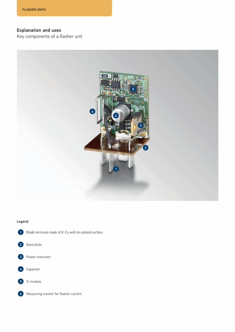
Explanation and usesKey components of a flasher unit
FLASHER UNITS
Legend
Blade terminal made of E-Cu with tin-plated surface
Base plate
Power transistor
Capacitor
IC module
Measuring resistor for flasher current

| 3332
Functional principle
� In terms of circuitry, every flasher unit is an “astable multivibrator”. Its role is to operate blinker lights at the statutory frequency of 1.5 +/- 0.5 Hz or 90 +/- 30 rpm. This value applies to both directional and hazard warning lights.
� Each flasher unit is assigned a separate output load or a permissible number of flashing indicator lights. This specific load case variant may not be exceeded or undercut, as otherwise the failure control will fail to work correctly. Some typical load cases which are supported are shown below:
Scenario Direction flashing Hazard warning flashing PictogramTowcar only 2 x 21 W 4 x 21 W
2 x 21 W + 0 … 5 W 4 x 21 W + 2 x 5 W
Towcar + 1 trailer 2 + 1 x 21 W 6 x 21 W
2 + 1 x 21 W + 0 … 5 W 6 x 21 W + 2 x 5 W
3 + 1 x 21 W 8 x 21 W
3 + 1 x 27 W (32 CP) + 3 W (SAE) 8 x 27 W (32 CP) + 2 x 3 W (SAE) –4 + 1 x 21 W 10 x 21 W
Towcar + 2 trailers 2 + 1 + 1 x 21 W 8 x 21 W
In addition to the load cases above, there are other use cases which do not feature failure control. These variants can be found in the tabular overview from page 38 on.
� The failure of an indicator light must be clearly displayed to the driver. The law permits failure control by doubling the flashing frequency (E-control) or the indicator control lamp remaining off (P-control). The failure control applies to motor vehicles and all trailers.
� Segmentation into different current and control circuits is typical of flashing circuits. We distinguish between:• Single-circuit flasher units• Dual-circuit flasher units• Three-circuit flasher units• Pulse generators
� In addition to the flasher circuits listed above, HELLA also supplies pulse generators. In principle, these are flasher units without failure control. In contrast to the above types, pulse generators can be operated with small loads (e.g. 10 W).

FLASHER UNITS
Rated voltage
� 6 V: for motorbikes etc. � 12 V: for passenger cars, agricultural and construction machinery etc. � 24 V: for commercial vehicles, buses, municipal vehicles etc.
Rated load, rated switching current(depending on load case)
� The number of connected flashing indicator lamps must not exceed the use cases/rated loads indicated for the respective flasher units
� Special-purpose variants available for LED lights
A
Contacts and connector configurations
Single-circuit flasher unitC Towcar failure control lampC2 1st trailer failure control lampC3 2nd trailer failure control lamp31 Ground49 Input49a Output
Dual-circuit flasher unitL Indicator, left (input)R Indicator, right (input)LL Towcar indicator, leftRL Towcar indicator, rightC Towcar failure control lampC2 1st trailer failure control lamp31 Ground49 Input49a Output54L Trailer indicator, left54R Trailer indicator, right
Three-circuit flasher unitL Indicator, left (input)R Indicator, right (input)LLH Towcar indicator,
left rearLLV Towcar indicator,
left frontRLH Towcar indicator,
right rearRLV Towcar indicator,
right frontC Towcar failure control lampC2 1st trailer failure control lampC3 2nd trailer failure control lamp31 Ground49 Input49a Output54L Trailer indicator, left54R Trailer indicator, right

| 3534 | 3534

Test circuits
FLASHER UNITS
21 W 21 W 21 W 5 W 5 W21 W
C 1,2 W
21 W 21 W 21 W 21 W
1,2 W
49
15/30
C2
1,2 W31 49 a
C3
1,2 W
C
C 1,2 W
54 L 54 R
21 W 21 W
21 W
21 W
21 W
21 W
LLV RLVL 49a
49
15/30
31
C C2 R
The single-circuit test circuit
Single-circuit units are used in load cases (per 21 W bulb) 2x, 4x, 5x, 2+1, 3+1, 2+1+1 for passenger cars, light commercial vehicles and tow vehicles. It is not possible to distinguish between the failure of a lamp on the towcar or on the trailer, as there is only one measuring resistor for the load current.
The dual-circuit test circuit
Dual-circuit units (separate test circuits for trailer and towcar) are typical in large commercial vehicles and help to minimise power losses caused by long cables and numerous connectors.
Load case variant Control types:Towcar 1st trailer 2nd trailer
2 (4) x 21 W + 5 W 12 V E, P – –2 + 1 (6) x 21 W + 5 W 12 / 24 V E, P P –3 + 1 (8) x 21 W 12 / 24 V P P –2 + 1 + 1 (8) x 21 W 12 V P P P
Load case variant Control types:Towcar 1st trailer
2 + 1 (6) x 21 W 12 / 24 V E, P P3 + 1 (8) x 21 W 12 / 24 V E, P P

| 3736
54 L 54 R
21 W 21 W
21 W 21 W
21 W
21 W
21 W
21 W
LLH LLV RLV RLHL 49a
49
15/30
31
C C2 R
The three-circuit test circuit
Three-circuit units (separate test circuits for front and rear indicators of the towcar and of the trailer) are useful for commercial vehicles and buses and help to minimise power losses caused by long cables and numerous connectors.
Due to the complexity of wiring, they are less common.
Load case variant Control types:Towcar 1st trailer
1 + 1… 3 + 1… 3 x 21 W 24 V P P1 + 1… 3 + 1… 3 x 21 W 24 V P P

FLASHER UNITS
Flasher unit 6V, 4-pole and 12V, 3-pole
Product photo Load case/rated power
Flas
hing
freq
uenc
y [pe
r m
inut
e]*
Brig
ht-li
ght t
ime
[%]*
Failure control
Pin
arra
ngem
ent
Volta
ge ra
nge
[V]
Tem
pera
ture
rang
e [°C
]
Hold
er
Part number
Direction flashing
Hazard warning flashing
C C2 C3
1 to 5 x 18 / 21 W
10 to 110 W 90 ± 15 46.5 ± 8.5 – – – BG 5 to 7.5 - 40 to + 85 Included 4AZ 003 787-051
Universal, pulse generator, without
failure control
Not permitted under StVZO (German Road Vehicle Registration
Regulation)
10 to 140 W 10 to 140 W 90 ± 15 50 ± 8 E – – BG1 9 to 16 - 40 to + 85 Included 4AZ 001 879-041
Universal, pulse generator, without
failure control
Not permitted under StVZO (German Road Vehicle Registration
Regulation)
2 x 21 W + 0 to 5 W
4 x 21 W + 2 x 5 W
90 ± 30 50 ± 5 E – – BG1 10 to 15 - 40 to + 85 Included 4DB 003 750-721
2 x 21 W + 5 W
2 x 32 cp + 5 W
4 x 21 W + 2 x 5 W
90 ± 15 50 ± 10 E – – BG1 9 to 16 - 40 to + 85 No 4DB 003 750-391
2 x 10 W 4 x 10 W 90 ± 30 57.5 ± 17.5 E – – BG1 10 to 15 - 40 to + 85 No 4DB 003 750-707
For motorbikes
* at room temperature and test voltage
C = TowcarC2 = 1st trailerC3 = 2nd trailer

| 3938
Flasher unit 12V, 3-pole
Product photo Load case/rated power
Flas
hing
freq
uenc
y [pe
r m
inut
e]*
Brig
ht-li
ght t
ime
[%]*
Failure control
Pin
arra
ngem
ent
Volta
ge ra
nge
[V]
Tem
pera
ture
rang
e [°C
]
Hold
er
Part number
Direction flashing
Hazard warning flashing
C C2 C3
2 x 21 W + 0 to 5 W
4 x 21 W + 2 x 5 W
90 ± 30 50 ± 5 E – – BG1 10 to 15 - 40 to + 85 No 4DB 003 750-711
10 W + 16 W 2 x 10 W + 2 x 16 W
87.5 ± 12.5 50 ± 3 E – – BG1 9 to 16 - 40 to + 85 No 4DB 003 750-737
For motorbikes
2 + 1 x 21 W + 5 W
6 x 21 W + 2 x 5 W
87 ± 18 50 ± 3 E P – BG1 10 to 15 - 30 to + 60 No 4DM 005 698-021
31 + C2 on top of housing
2 x 21 W + 0 to 5 W
4 x 21 W + 2 x 5 W
80 ± 15 50 ± 10 E – – BG2 11 to 15 - 20 to + 60 Included 4DB 001 887-041
2 + 1 x 21 W + 0 to 5 W
6 x 21 W + 2 x 5 W
87.5 ± 12.5 50 ± 3 E P – BG3 9 to 16 - 40 to + 85 Included 4DM 003 360-021
31 + C2 on top of housing
* at room temperature and test voltage
C = TowcarC2 = 1st trailerC3 = 2nd trailer

FLASHER UNITS
Flasher unit 12V, 4-pole
Product photo Load case/rated power
Flas
hing
freq
uenc
y [pe
r m
inut
e]*
Brig
ht-li
ght t
ime
[%]*
Failure control
Pin
arra
ngem
ent
Volta
ge ra
nge
[V]
Tem
pera
ture
rang
e [°C
]
Hold
er
Part number
Direction flashing
Hazard warning flashing
C C2 C3
3 + 1 x 21 W 8 x 21 W 85 ± 15 50 ± 3 E P – BG3 10 to 15 - 25 to + 75 No 4DW 003 390-061
10 to 200 W 10 to 200 W 82.5 ± 12.5 52 ± 3 – – – BG 9 to 16 - 40 to + 85 Included 4AZ 003 787-081
Universal, pulse generator, without
failure control
Not permitted under StVZO (German Road Vehicle Registration
Regulation)
3 +1 x 21 W 8 x 21 W 90 ± 20 50.5 ± 4.5 E P – BG3 9 to 16 - 40 to + 85 No 4DW 004 639-077
2 + 1 x 21 W + 5 W
6 x 21 W + 2 x 5 W
87 ± 18 50 ± 3 E P – BG4 10 to 15 - 30 to + 60 No 4DM 005 698-031
31 + C2 on top of housing
2 x 21 W + 0 to 5 W
4 x 21 W + 2 x 5 W
87.5 ± 12.5 50 ± 3 E – – BG4 10 to 15 - 40 to + 70 No 4DB 007 218-001
* at room temperature and test voltage
C = TowcarC2 = 1st trailerC3 = 2nd trailer

| 4140
Flasher unit 12V, 5-pole/6-pole
Product photo Load case/rated power
Flas
hing
freq
uenc
y [pe
r m
inut
e]*
Brig
ht-li
ght t
ime
[%]*
Failure control
Pin
arra
ngem
ent
Volta
ge ra
nge
[V]
Tem
pera
ture
rang
e [°C
]
Hold
er
Part number
Direction flashing
Hazard warning flashing
C C2 C3
2 + 1 x 21 W + 5 W
6 x 21 W + 2 x 5 W
85 ± 15 50 ± 3 P P – BG5 11 to 15 - 30 to + 60 Yes 4DM 003 460-021
3 + 1 x 27 W + 3 W
3 + 1 x 32 cp + 3 W
8 x 27 W + 2 x 3 W
97 ± 10 50 ± 5 – – – BG8 10 to 15 - 30 to + 70 Included 4AZ 006 252-021
Universal, pulse generator, without
failure control
Not permitted under StVZO (German Road Vehicle Registration
Regulation)
For SAE
2 + 1 + 1 x 21 W
8 x 21 W 90 ± 15 50 ± 5 E P P BG7 9 to 16 - 40 to + 85 No 4DN 008 768-001
2 + 1 + 1 x 21 W
8x 21 W 90 ± 15 50 ± 5 E P P BG7 9 to 16 - 40 to + 85 Yes 4DN 008 768-011
2 + 1 + 1 x 21 W
8 x 21 W 90 ± 15 50 ± 5 E P P BG7 9 to 16 - 40 to + 85 Yes 4DN 008 768-021
* at room temperature and test voltage
C = TowcarC2 = 1st trailerC3 = 2nd trailer

FLASHER UNITS
Flasher unit 12V, 6-pole/7-pole
Product photo Load case/rated power
Flas
hing
freq
uenc
y [pe
r m
inut
e]*
Brig
ht-li
ght t
ime
[%]*
Failure control
Pin
arra
ngem
ent
Volta
ge ra
nge
[V]
Tem
pera
ture
rang
e [°C
]
Hold
er
Part number
Direction flashing
Hazard warning flashing
C C2 C3
2 + 1 + 1 x 21 W
8 x 21 W 90 ± 15 50 ± 5 E P P BG7 9 to 16 - 40 to + 85 Yes 4DN 008 768-031
Holder angled at 90°
2 + 1 + 1 x 21 W
8 x 21 W 90 ± 15 50 ± 5 E P P BG7 9 to 16 - 40 to + 85 Yes 4DN 008 768-041
Holder angled at 90°, with vibration
damper
2 + 1 + 1 x 18 W
8 x 18 W 90 ± 15 50 ± 5 E P P BG7 9 to 16 - 40 to + 85 Yes 4DN 008 768-051
Holder angled at 90°, with vibration
damper
2 + 1 + 1 x 21 W
8 x 21 W 90 ± 30 52.5 ± 22.5 P P P BG7 10.8 to 15
- 40 to + 85 Yes 4DN 996 173-017
2 x 21 W + 0 to 5 W
4 x 21 W + 2 x 5 W
87.5 ± 17.5 52.5 ± 7.5 E – – BG10 9 to 16 - 40 to + 85 Included 4DB 006 716-041
* at room temperature and test voltage
C = TowcarC2 = 1st trailerC3 = 2nd trailer

| 4342
Flasher unit 24V, 3-pole/4-pole
Product photo Load case/rated power
Flas
hing
freq
uenc
y [pe
r m
inut
e]*
Brig
ht-li
ght t
ime
[%]*
Failure control
Pin
arra
ngem
ent
Volta
ge ra
nge
[V]
Tem
pera
ture
rang
e [°C
]
Hold
er
Part number
Direction flashing
Hazard warning flashing
C C2 C3
10 to 140 W 10 to 140 W 90 ± 15 50 ± 8 – – – BG1 18 to 32 - 40 to + 85 Yes 4AZ 001 879-051
Universal, pulse generator, without
failure control
Not permitted under StVZO (German Road Vehicle Registration
Regulation)
2 x 21 W + 0 to 5 W
4 x 21 W + 2 x 5 W
87.5 ± 12.5 50 ± 3 E – – BG1 20 to 30 - 40 to + 85 No 4DB 003 675-011
10 bis 200 W 10 to 200 W 90 ± 15 46.5 ± 8.5 – – – BG 20 to 32 - 40 to + 85 Included 4AZ 003 787-071
Universal, pulse generator, without
failure control
Not permitted under StVZO (German Road Vehicle Registration
Regulation)
3 + 1 x 21 W 8 x 21 W 95 ± 20 50 ± 10 E P – BG3 20 to 30 - 30 to + 70 No 4DW 004 513-021
Silent
4 + 1 x 21 W 10 x 21 W 95 ± 20 50 ± 10 E P – BG3 20 to 30 - 30 to + 70 No 4DW 004 513-031
Silent
* at room temperature and test voltage
C = TowcarC2 = 1st trailerC3 = 2nd trailer
FLASHER UNITS
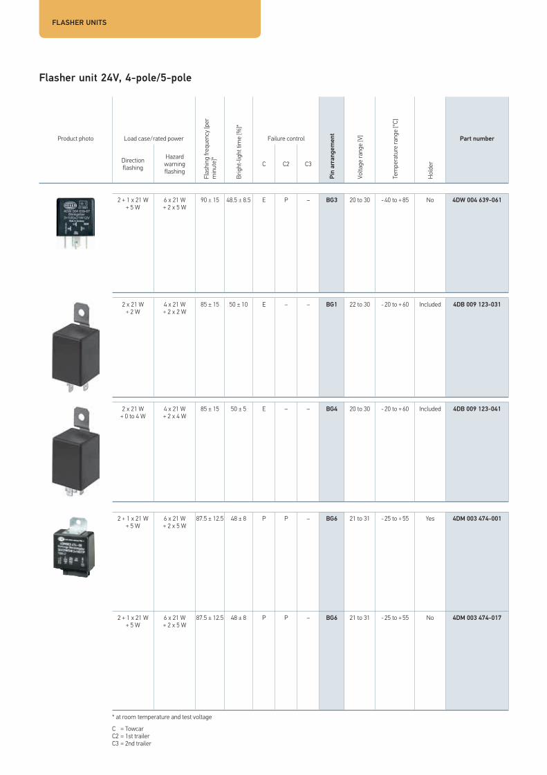
Flasher unit 24V, 4-pole/5-pole
Product photo Load case/rated power
Flas
hing
freq
uenc
y [pe
r m
inut
e]*
Brig
ht-li
ght t
ime
[%]*
Failure control
Pin
arra
ngem
ent
Volta
ge ra
nge
[V]
Tem
pera
ture
rang
e [°C
]
Hold
er
Part number
Direction flashing
Hazard warning flashing
C C2 C3
2 + 1 x 21 W + 5 W
6 x 21 W + 2 x 5 W
90 ± 15 48.5 ± 8.5 E P – BG3 20 to 30 - 40 to + 85 No 4DW 004 639-061
2 x 21 W + 2 W
4 x 21 W + 2 x 2 W
85 ± 15 50 ± 10 E – – BG1 22 to 30 - 20 to + 60 Included 4DB 009 123-031
2 x 21 W + 0 to 4 W
4 x 21 W + 2 x 4 W
85 ± 15 50 ± 5 E – – BG4 20 to 30 - 20 to + 60 Included 4DB 009 123-041
2 + 1 x 21 W + 5 W
6 x 21 W + 2 x 5 W
87.5 ± 12.5 48 ± 8 P P – BG6 21 to 31 - 25 to + 55 Yes 4DM 003 474-001
2 + 1 x 21 W + 5 W
6 x 21 W + 2 x 5 W
87.5 ± 12.5 48 ± 8 P P – BG6 21 to 31 - 25 to + 55 No 4DM 003 474-017
* at room temperature and test voltage
C = TowcarC2 = 1st trailerC3 = 2nd trailer

| 4544
Flasher unit 24V, 6-pole/7-pole
Product photo Load case/rated power
Flas
hing
freq
uenc
y [pe
r m
inut
e]*
Brig
ht-li
ght t
ime
[%]*
Failure control
Pin
arra
ngem
ent
Volta
ge ra
nge
[V]
Tem
pera
ture
rang
e [°C
]
Hold
er
Part number
Direction flashing
Hazard warning flashing
C C2 C3
3 + 1 x 21 W 8 x 21 W 90 ± 15 53.5 ± 8.5 P P – BG9 21.6 to 30
- 40 to + 85 Yes 4DW 003 944-071
2 + 1 x 21 W + 5 W
6 x 21 W + 2 x 5 W
90 ± 15 48.5 ± 8.5 P P – BG9 21.6 to 30
- 40 to + 85 No 4DM 003 944-081
2 + 1 x 21 W + 5 W
6 x 21 W + 2 x 5 W
90 ± 15 48.5 ± 8.5 P P – BG9 21.6 to 30
- 40 to + 85 Yes 4DM 003 944-091
2 + 1 x 21 W + 0 to 5 W
6 x 21 W + 2 x 5 W
90 ± 30 57.5 ± 17.5 E P – BG9 21 to 28 - 40 to + 85 No 4DM 006 475-087
2 + 1 + 1 x 21 W
8 x 21 W 85 ± 15 50 ± 20 P P P BG11 20 to 30 - 30 to + 85 Yes 4DN 009 124-011
* at room temperature and test voltage
C = TowcarC2 = 1st trailerC3 = 2nd trailer

| 4746Flasher units
Flasher unit 24 V, 11-pole and 12/24 V, 6-pole
Product photo Load case/rated power
Flas
hing
freq
uenc
y [pe
r m
inut
e]*
Brig
ht-li
ght t
ime
[%]*
Failure control
Pin
arra
ngem
ent
Volta
ge ra
nge
[V]
Tem
pera
ture
rang
e [°C
]
Hold
er
Part number
Direction flashing
Hazard warning flashing
C C2 C3
1 to 4 x 18 / 21 W
2 to 8 x 18 / 21 W
90 ± 30 50 ± 20 – – – BG12 22 to 30 - 30 to + 70 Yes 4DZ 002 834-162
1 to 8 x 18 / 21 W
8 x 18 / 21 W 90 ± 15 37.5 ± 5.5 – – – BG9 10 to 32 - 20 to + 70 Yes 4DZ 004 019-021
* at room temperature and test voltage
C = TowcarC2 = 1st trailerC3 = 2nd trailer

| 4746
LED flasher unit 12/24V, 3-pole; 12V, 4-pole/5-pole and 24V, 4-pole
Product photo Load case/rated power
Flas
hing
freq
uenc
y [pe
r m
inut
e]*
Brig
ht-li
ght t
ime
[%]*
Failure control
Pin
arra
ngem
ent
Volta
ge ra
nge
[V]
Tem
pera
ture
rang
e [°C
]
Hold
er
Part number
Direction flashing
Hazard warning flashing
C C2 C3
42 W 42 W 90 ± 30 50 ± 10 – – – BG1 9 to 33 - 40 to + 85 No 4JZ 177 846-007
Universal, pulse generator, without
failure control
Not permitted under StVZO (German Road Vehicle Registration
Regulation)
3 + 1 x 21 W 8 x 21 W 90 ± 30 57.5 ± 17.5 E P – BG2 10 to 15 - 40 to + 85 Included 4DW 009 492-111
2 + 1 + 1 x 21 W
8 x 21 W 90 ± 30 57.5 ± 17.5 E P P BG13 10 to 15 - 40 to + 85 Included 4DN 009 492-101
2 + 1 x 21 W 6 x 21 W 90 ± 30 57.5 ± 17.5 E P – BG2 18 to 32 - 40 to + 85 Included 4DM 009 492-001
3 + 1 x 21 W 8 x 21 W 90 ± 30 57.5 ± 17.5 E P – BG2 18 to 32 - 40 to + 85 Included 4DW 009 492-011
* at room temperature and test voltage
C = TowcarC2 = 1st trailerC3 = 2nd trailer

FLASHER UNITS
HELLA flasher units comply with national and international regulations: � StVZO Article 54 direction indicators � ECE guideline 48 lighting devices � EC Directive 76/756 lighting devices � US Federal Standard FMV88 108 lighting devices � SAE J590 turn signal flashers � SAE J945 vehicle hazard warning signal flashers � EC Directive 72/245 radio interference
Legal regulations for flasher units
Overview of flasher unit technical data
GENERAL AND ELECTRICAL DATA
Rated voltage 12 V 24 V
Test voltage 13 V 28 V
Test temperature 23°C ± 5°C 23°C ± 5°C
Flashing cycle 90 ± 30 Flashing cycle/min 90 ± 30 Flashing cycle/min
Bright-light time normal 50 % ± 10 % 50 % ± 10 %
Bright-light time with rapid flashing 40 % ± 5 % 40 % ± 10 %
Control type E / P, EP, PP, PPP EP, PP
Voltage drop 49 � 49a 49 � 49a < 450 mV 450 mV
Short-circuit strength 49 � 49a 49 � 49a 15 A fuse 15 A fuse
Minimum device protectionIP 54 according to
ISO 20653IP 54 according to
ISO 20653

| 4948
Safe conversion to LED indicators using HELLA electronics according to ISO 13207-1 As indicators must be checked by law, we recommend operating the lights only in conjunction with a failure control according to ISO 13207-1.
For LED indicators with a control pulse, HELLA offers electronic ballasts which make it possible to display indicator failure for various vehicle assemblies and modifications. This is necessary if the vehicle manufacturer does not guarantee indicator bulb failure control via the vehicle electric system.
There are three different ballasts and several different LED indicators available:
As a new solution, HELLA recommends detecting the electrical pulse directly in the vehicle manufacturer’s vehicle electric system. It is merely necessary to integrate the check according to ISO 13207-1. This obviates the need for interim solutions via the indicator control units.
Legal requirement in all ECE statesIn the case of vehicles approved for use on public roads, the indicators must be monitored: the failure of an indicator must be shown optically or acoustically in the vehicle. This applies to all ECE states in which regulation ECE R 48 is in effect. This means possible indicator failure must be monitored by the vehicle. Manufacturers use different control procedures for this.
The failure controls currently in use cannot detect simple LED lights and indicate a fault. Many HELLA LED indicators have integrated failure control electronics. The indicators are self-monitoring. When functioning correctly, they create a pulse according to ISO 13207-1 which can be evaluated by the vehicle electronics. If the available vehicle electronics cannot evaluate the pulse themselves, HELLA provides various solutions for evaluating this pulse, shown below.
As soon as one single LED fails, the light can be considered faulty, the impulse is not generated. In this case, for instance, the ballast switches off the bulb simulation and the flasher unit reports the error to the driver.
LED indicator control unit LED flasher unit Simulation device for cold checking Vehicle electric system check according to ISO 13207-1
LED indicators and failure control from HELLA
LED light failure control and correct electrical connection
Operation of the LED lamp with alternating voltage or clocked direct voltage is not permitted. The individual light functions may only be operated with a vehicle fuse of max. 3A.
Due to the low watt output of LED lights, which are distinctly different from a bulb version, problems can arise in bulb failure control when operating traction vehicles. As checking of the indicators is required by law, we recommend operating the light only in conjunction with the indicator control unit, HELLA part no. 5DS 009 552-xxx.
In addition, further lighting functions are detected by some towing vehicles. This is a vehicle comfort function which is not required by legislation and does not release drivers from their obligation to see for themselves that the lighting equipment is working. Here, too, faulty diagnosis can occur on account of the low power levels involved (instrument panel in the driver cab indicates light failure although the function is working).
Should misdiagnosis occur, as described above, while operating your traction vehicle, please contact the traction vehicle manufacturer.

Solution 1: LED flasher unit
Solution 2:Simulation device for cold checking
Is a flasher relay installed in the vehicle? YesStart
YesAny failure of the flasher unit is displayed.
No Press the signal switch
Turn on the vehicle ignition and remove the bulb of a direction indicator without pressing the signal switch.
No
YesAny failure of the flasher unit is displayed.
No Vehicle not ECE-compliant
UNIVERSAL SOLUTIONfor 24V vehicle electric systems
12 V 24 V
Operating voltage 10 – 15 V 18 – 32 V
Functional voltage 11 – 14 V 20 – 28 V
Operating temperature -40° to +85°C -40° to +85°C
Protection class IP 53 (contacts underneath) IP 53 (contacts underneath)
LED flasher unit 3+1
4DW 009 492-111 4DW 009 492-011
LED flasher unit 2+1
– 4DM 009 492-001
LED flasher unit 2+1+1
4DM 009 492-101 –
The right solution for your vehicle electronics
ISO 13207-1 SOLUTIONfor 24V vehicle electric systems
12 V 24 V
Operating voltage 9 – 16 V 18 – 32 V
Rated current 1.5 A 1.5 A
Operating temperature -40° to +85°C -40° to +85°C
Protection class IP 54 (contacts underneath) IP 54 (contacts underneath)
Simulation device
5DS 009 602-011 5DS 009 602-001

| 5150
In future, vehicle manufacturers’ light control units will be able to check the failure pulse in a standardised and unified manner according to ISO 13207-1.
Interim solutions 1 to 3 are therefore unnecessary, as communication takes place directly with the indicators. HELLA recommends this solution.
Since not every vehicle currently has its own vehicle electric system, this solution must be integrated.
Solution 3:Indicator control unit Universal solution
Solution 4:Light control unit with integrated check of the failure pulse according to ISO 13207-1
Solution 1: Replace the existing indicator unit with an LED indicator unit from HELLA with an ISO pin base
One flasher unit per vehicle required. Any possible combination of bulbs and HELLA LED direction indicators is permitted: from a full package with bulbs through mixed versions to a full package with LED lights. Bulbs or HELLA LED direction indicators are also permitted on trailers.
Solution 2: Through simulation unit for cold check
One simulation device is required per LED light.
Solution 3: By LED indicator control unit
Two LED direction indicators can be monitored per vehicle using one simulation device.
(Only one simulation device per vehicle can be used.)
24 V
Operating voltage 18 – 32 V
Reverse-polarity protection voltage - 28 V
On-board voltage inputFlasher unit left / right 24 V
Operating temperature -40 to +50 °C
Extended operating temperature* – 40 °C to 80 °C
Storage temperature – 40 °C to 90 °C
With blade terminal sleeves 5DS 009 552-011
For EasyConn connectors 5DS 009 552-001
* Simulation of the filament bulb is deactivated for thermal reasons if the temperature exceeds 50°C.
Solution 3: By LED indicator control unit
Solution 4: By monitoring in compliance with ISO 13207-1 in the vehicle manufacturer’s vehicle electric system.
Failu
re p
ulse
acc
ordi
ng to
ISO
1320
7-1
2BA 959 070-631
2BA 959 050-401
2BA 959 822-601
2BA 344.200-...
2BA 343 390-...
2SD 343 910-...

WASH/WIPE INTERVAL CONTROL UNITS
Explanation and usesKey components of a wash/wipe interval control unit
Legend
Blade terminal made of E-Cu with tin-plated surface
Base plate
Capacitor
PCB relay
SMD components (resistors, diodes etc.)

| 5352
Functional principle
The wash/wipe interval control unit essentially comprises a pulse generator with a fixed or variable pulse/pause ratio. Every pulse with which the wipe/wash motor is controlled via a relay causes a one-off back-and-forth movement of the windshield wipers. Depending on the design, the length of the wipe pause is 4 s to X s.
The WWI control unit comprises the following: � PCB with electronic components, blade terminals and a PCB relay � Synthetic material housing, sometimes with holder
Similarly to flasher units, the timer is designed as an astable multivibrator in the wipe/wash interval control unit. A failure control stage as required by the flasher system is not needed for the WWI control unit.
HELLA also supplies headlight washer systems which clean the headlights using a spray of high-pressure water. Depending on the variant, the length of the spray varies between 0.4 s and 0.8 s.
Rated voltage
� 12 V: for passenger cars, agricultural and construction machinery etc. � 24 V: for commercial vehicles, buses, municipal vehicles etc.
Rated load, rated switching current
� 3.5 A to 10 A, depending on vehicle type
A
Contacts and connector configurations
Wash/wipe interval control unitsI Intermittent wiping (input)S, 53 M Wiper motor field winding
(output)T, 86 Wash button (input)15 Battery +, switched (input)31 Ground31b, 53S Wiper motor cam switch/
park position/limit switch(input)
Headlight cleaning system control unitP Water pump (output)S Actuating switch (input)30 Load current +, terminal 15 (input)31 Ground56 Light (input)

WASH/WIPE INTERVAL CONTROL UNITS
Wash/wipe interval control units 12V
Product photo Function times [s] Load current [A]
Pin
arra
ngem
ent
Volta
ge ra
nge
[V]
Tem
pera
ture
rang
e [°C
]
Hold
er
Part number
■ □ ◊ Make contact
Break contact
4 ± 1 1 5 ± 1 10 – I 9 to 16 - 30 to + 70 Yes 5WG 002 450-111
4 ± 1 1 5 ± 1 3.5 – I 9 to 16 - 40 to + 85 Yes 5WG 002 450-311
6 ± 1 1 6 ± 1 5 – BG8 11 to 16 - 30 to + 85 No 5WG 003 620-081
3.9 ± 1 0.8 to 0.4 6.5 ± 1.5 20 10 I1 10 to 15 - 20 to + 60 No 5WG 996 165-001
■ Release delay, wipe/wash operation
□ Turn-on delay, intermittent operation
◊ Pause time, intermittent operation

| 5554
Wash/wipe interval control units 24V
Product photo Function times [s] Load current [A]
Pin
arra
ngem
ent
Volta
ge ra
nge
[V]
Tem
pera
ture
rang
e [°C
]
Hold
er
Part number
■ □ ◊ Make contact
Break contact
4 ± 1 1 5 ± 1 10 – I2 21 to 30 - 30 to + 70 Yes 5WG 002 450-121
4 ± 1 1 5 ± 1 3.5 – I 21.2 to 30 - 40 to + 85 Yes 5WG 002 450-287
4 ± 1 1 5 ± 1 3.5 – I 21.2 to 30 - 40 to + 85 Yes 5WG 002 450-291
4 ± 1 1 5 ± 1 3.5 – I 21.2 to 30 - 40 to + 85 No 5WG 002 450-301
■ Release delay, wipe/wash operation
□ Turn-on delay, intermittent operation
◊ Pause time, intermittent operation

WASH/WIPE INTERVAL CONTROL UNITS
Headlight cleaning system 12V/24V
Product photo Duty time Output [s]
Pin
arra
ngem
ent
Rate
d vo
ltage
[V]
Volta
ge ra
nge
[V]
Tem
pera
ture
rang
e [°C
]
Part number
0.8 ± 0.04 SW 12 9 to 15 - 40 to + 90 5WD 005 674-131
0.6 ± 0.06 SW 12 9 to 15 - 40 to + 90 5WD 005 674-151
0.43 ± 0.02 SW 24 18 to 30 - 40 to + 90 5WD 003 547-071
0.8 ± 0.04 SW 24 18 to 30 - 40 to + 90 5WD 005 674-141

| 5756 | 5756
CLOCK RELAYS
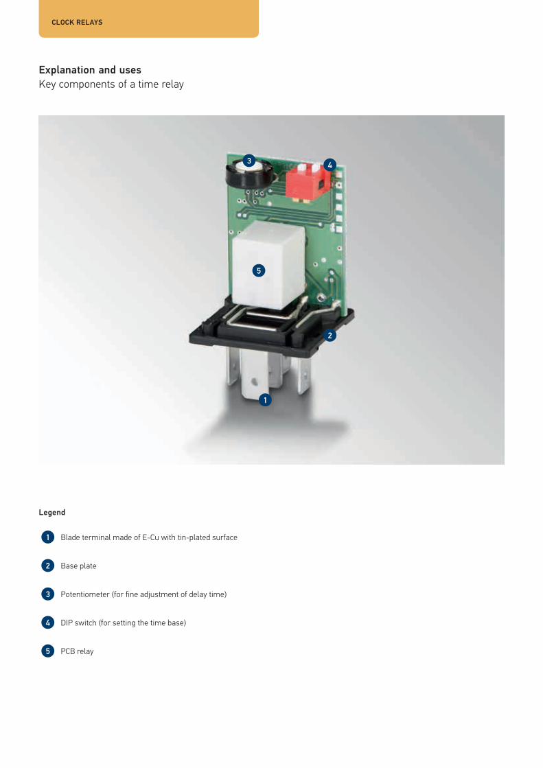
Explanation and usesKey components of a time relay
Legend
Blade terminal made of E-Cu with tin-plated surface
Base plate
Potentiometer (for fine adjustment of delay time)
DIP switch (for setting the time base)
PCB relay

| 5958
Functional principle
A time relay is a monostable flip-flop with connected relay.
The time relay is available in two variants: � Pick-up delay: the monostable flip-flop is activated by applying a voltage to the device input. Depending on the
set time, the relay is then switched on with a delay. After deactivating the input, the relay voltage drops immediately.
� Drop-off delay: the relay is switched on immediately by applying a voltage to the input of the monovibrator. After deactivating the input, the relay voltage drops after a predetermined time.
HELLA also supplies time relays with neither pick-up nor drop-off delay. In this case, the output is activated or switched on for a specific period of time.
The delay or turn-on time can be adjusted with a DIP switch and fine-tuned with a potentiometer.
If a more powerful relay is used, higher current strengths or different load types – e.g. inductive, capacitive/lamps – can be easily activated.
Rated voltage � 12 V: for passenger cars, agricultural and construction machinery etc. � 24 V: for commercial vehicles, buses, municipal vehicles etc.
Rated load, rated switching current
� Up to 20 A, make contact � Up to 10 A, break contactA
Contacts and connector configurations
HL Handbrake control (input)HK Handbrake contact (input)L, 87 Load current, make contact (output)N Emergency-off switch (input)S, 15 Actuating switch (input)SK Grounding contact (input)30 Load current +, terminal 15 (input)31 Ground87a Load current, break contact (output)

CLOCK RELAYS
Clock relays 12V
Product photo Duty time Output [s] Load current [A]
Pin
arra
ngem
ent
Volta
ge ra
nge
[V]
Tem
pera
ture
rang
e [°C
]
Hold
er
Part number
With turn-on delay
With turn-off delay
Make contact
Break contact
2 ± 0.7 – X 0.31 – Z2 10 to 15 -10 to + 60 No 5HE 003 724-027
25 ± 5 – – 10 – Z3 10 to 15 -20 to +85 No 5HE 004 911-037
5 ± 1.5 – – 10 – Z1 9 to 16 -40 to +85 No 5HE 006 207-027
10 - 5 / 120 ± 30
– – 20 10 Z 9 to 15 -25 to +80 Included 5HE 996 152-087
0 to 900 ± 90
– X 20 10 Z 9 to 16 -25 to +80 Included 5HE 996 152-131
0 to 900 ± 90
X – 20 10 Z 9 to 16 -25 to +80 Included 5HE 996 152-151

| 6160
Clock relays 24V
Product photo Duty time Output [s] Load current [A]
Pin
arra
ngem
ent
Volta
ge ra
nge
[V]
Tem
pera
ture
rang
e [°C
]
Hold
er
Part number
With turn-on delay
With turn-off delay
Make contact
Break contact
0.8 ± 0.2 – – 5 5 Z5 18 to 32 - 40 to + 85 No 5HE 009 130-001
1.5 ± 0.5 X – 3 – Z4 18 to 32 - 40 to + 85 No 5HE 004 236-017
0.9 ± 0.09 X – 10 5 Z 18 to 32 - 40 to + 85 Included 5HE 996 152-127
0 to 900 ± 90
– X 20 10 Z 18 to 32 - 25 to + 80 Included 5HE 996 152-141
0 to 900 ± 90
X – 20 10 Z 18 to 32 - 25 to + 80 Included 5HE 996 152-161
5 ± 0,5 – X 20 10 Z 18 to 32 - 25 to + 80 Included 5HE 996 152-177

Overview
ACCESSORIES
Product photo Product description Available accessories Part number
Female connector housing, 2-pole Blade terminal sleeve: 8KW 744 837-002,
Single conductor seal: 9GD 746 185-002
8JA 746 184-022
Female connector housing, 4-pole Blade terminal sleeves and single conductor seals, enclosed separately
8KW 188 577-001
Female connector housing, 5-pole Blade terminal sleeves:8KW 744 819-003,8KW 701 235-…,8KW 744 820-003
8JA 715 606-001
Female connector housing, 5-pole Blade terminal sleeve:8KW 719 874-007
8JA 717 291-007
Female connector housing, 5-pole Pin contacts already equipped 8JA 733 963-001
Female connector housing, 5-pole Blade terminal sleeves:8KW 744 819-003,8KW 701 235-…,8KW 744 820-003,8KW 733 815-003
8JD 733 767-001
Female connector housing, 5-pole Pin contacts already equipped 8JD 733 962-001

| 6362
Product photo Product description Available accessories Part number
Female connector housing, 5-pole With pre-fitted cable assembly 8JD 745 801-001
Female connector housing, 5-pole Blade terminal sleeves:8KW 863 904-003,8KW 863 904-013
8JD 745 801-011
Cable sachet housing, 6-pin Blade terminal sleeves:8KW 744 819-003,8KW 701 235-…,8KW 744 820-003
9NH 701 230-001
Cable sachet housing, 8-pin Blade terminal sleeves:8KW 744 819-003,8KW 701 235-…,8KW 744 820-003
8JD 008 151-061
Cable sachet housing, 9-pin,mountable side by side
Blade terminal sleeves:8KW 744 819-003,8KW 701 235-…,8KW 744 820-003
8JA 003 526-001
Cable sachet housing, 9-pin,mountable side by side
Blade terminal sleeves:8KW 744 819-003,8KW 701 235-…,8KW 744 820-003,8KW 744 822-003
8JA 183 161-002

Circuit diagrams – electromechanical relays
SWITCHING AND PLUG MATRICES
| 6564
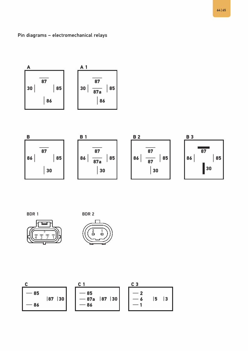
Pin diagrams – electromechanical relays
BDR 1 BDR 2

Pin diagrams – flasher units
SWITCHING AND PLUG MATRICES
BG BG1 BG2 BG3
BG4 BG5 BG6 BG7
BG8 BG9 BG10 BG11
BG12 BG13

| 6766
I I1 I2
Z Z1 Z2 Z3
Z4 Z5
SW
Pin diagrams – wash/wipe interval control units
Pin diagrams – control units for headlight cleaning systems
Pin diagrams – clock relays

HELLA ROCKER SWITCHESHELLA ROCKER SWITCHES
The new HELLA switch configurator
www.hella.com/switch

| 6968
HELLA module switch configuration toolConfigure your switches yourself! First, choose between the new waterproof 3100 series (interior and exterior applications) or the 4100 series (interior applications).
You can select any switch functions as well as the operating voltage, combinations of symbols and the corresponding accessories with only a few clicks. They can easily be transferred to a favourites list, printed out or sent as an online request.
Your request will be processed individually with the desired symbol configuration and customer-specific article number on a project-specific basis.
| 6968

Rocker switch, 3100 series
HELLA ROCKER SWITCHES
TECHNICAL DATA
Mounting opening 21.1 mm x 37.0 mm
Material rocker PC transparent, painted
Base plate material PBT
Connecting contacts 6.3 mm x 0.8 mm
Coating of switch contacts CuZn silver-plated
Light source
Max. 2 LEDs1 x orientation light, green1 x function light, redWarning lights available in amber and green
Symbol type lasered
Design life 6 A/24 V at 150,000 switching cycles
Leak tightness IP 68, IP 66 terminal side
Operating temperature - 40°C to + 85°C
Storage temperature - 40°C to + 85°C
Dashboard thickness For directly installed switches, 2 mm
ACCESSORIES
Installation frame
Modular
End piece left, right 9AR 169 209-102 / -107
Centre piece 9AR 169 208-102 / -107
Dummy cover 9HB 172 229-102 / -107
Female connector housing
Type I 8JD 010 076-102 / -107
Type II 8JD 010 076-112 / -117
Type III 8JD 010 076-122 / -127
Blade terminal sleeve, 6.3 mm
0.5 mm² to 1 mm² 8KW 744 882-003
1.5 mm² to 2.5 mm² 8KW 744 820-003
Dismantling tool 8PE 197 631-001
� IP 68 according to test standard IEC EN 60529 � Extremely reliable in extreme conditions � Ideal for use in agricultural and construction machinery � Wide range of switching functions 12/24 V
- Make contact/change-over contact- Button/latch- Disable function- Hazard light switch
� Wide range of standard and customer-specific laser symbols � Up to two LED light sources enable direct symbol illumination � Simple to install, directly in the mounting hole or using a
modular mounting frame � Display lights in the same design for safety-related feedback
The new waterproof series of rocker switches for electrical systems. Meets the requirements of protection class IP 68. The lasered symbols are lit by integrated LEDs.
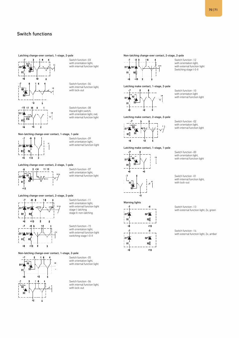
| 7170
Switch functions
Latching change-over contact, 1-stage, 2-poleSwitch function -03with orientation light,with internal function light
Switch function -04with internal function light,with lock-out
Switch function -08Hazard light switch, with orientation light, red,with internal function light
Non-latching change-over contact, 1-stage, 1-poleSwitch function -09with orientation light,with external function light
Latching change-over contact, 2-stage, 1-poleSwitch function -07with orientation light,with internal function light
Latching change-over contact, 2-stage, 2-poleSwitch function -11with orientation light, with external function lightstage I: latchingstage II: non-latching
Switch function -15with orientation light,with external function lightswitching stage I-0-II
Non-latching change-over contact, 1-stage, 2-poleSwitch function -05with orientation light, with internal function light
Switch function -06with internal function light,with lock-out
Non-latching change-over contact, 2-stage, 2-poleSwitch function -12with orientation light,with external function lightSwitching stage I-0-II
Latching make contact, 1-stage, 2-poleSwitch function -10with orientation lightwith internal function light
Latching make contact, 2-stage, 2-poleSwitch function -02with orientation light,with internal function light
Latching make contact, 1-stage, 1-poleSwitch function -00with orientation light,with internal function light
Switch function -01with internal function light,with lock-out
Warning lightsSwitch function -13with external function light, 2x, green
Switch function -14with external function light, 2x, amber

HELLA KGaA Hueck & Co.Rixbecker Straße 7559552 Lippstadt/GermanyTel.: +49 2941 38-0Fax: +49 2941 38-7133E-Mail: [email protected]: www.hella.com
HELLA Benelux BVCelsiusbaan 2, Postbus 13983430 BJ NieuwegeinNederlandT 030-6095611F 030-6051677E [email protected] www.hella.nl
Langlaarsteenweg 1682630 AartselaarBelgië T 03-887 97 21F 03-887 56 18E [email protected] www.hella.be
HELLA CZ, s.r.o.Revoluční 785285 22 Zruč nad SázavouČeská republikaTel.: (+420) 327 536 425 (+420) 606 619 472Fax: (+420) 327 536 421Internet: www.hella.cze-mail: [email protected]/hella.czech
© HELLA KGaA Hueck & Co., Lippstadt 9Z2 999 135-961 J00845/GR/10.14/1.0 Printed in GermanySubject to technical and price modifications.
HELLA Asia Singapore Pte LtdRegional Headquarters Asia PacificIndependent Aftermarket2 International Business Park#02-12 The StrategySingapore 609930Tel: +65 6854 7300Fax: +65 6854 7302E-mail: [email protected]: www.hellaasia.com
HELLA Automotive South Africa (Pty) LtdP O Box 6130Moselville, Uitenhage,SOUTH AFRICA6232Tel.: +27 (0) 41-996-5700Fax.: +27 (0) 41-996-5720http://www.hella.co.za
www.hella.com