relay i/o module: installationa and configuration · relay i/o module: installation and...
TRANSCRIPT
Installation andConfiguration
Relay I/O Module
AP9610
990-0125.book Page 1 Friday, February 9, 2007 4:44 PM
Relay I/O Module: Installation and Configuration
Contents
i
Preliminary Information . . . . . . . . . . . . . . . . . . . . . . . . . . . . . . . . . 1Introduction . . . . . . . . . . . . . . . . . . . . . . . . . . . . . . . . . . . . 1
Product description . . . . . . . . . . . . . . . . . . . . . . . . . . . . . . 1
Planning Your Configuration. . . . . . . . . . . . . . . . . . . . . . . . . . . . . 2Operating considerations . . . . . . . . . . . . . . . . . . . . . . . . . 2
Output contact ratings . . . . . . . . . . . . . . . . . . . . . . . . . . . . 2
Connection strategies . . . . . . . . . . . . . . . . . . . . . . . . . . . . 3
Dry contact I/O pinout . . . . . . . . . . . . . . . . . . . . . . . . . . . . 4
Accessory connection board . . . . . . . . . . . . . . . . . . . . . . . 5
Configuration Switch Settings . . . . . . . . . . . . . . . . . . . . . . . . . . . 6
Test Operation . . . . . . . . . . . . . . . . . . . . . . . . . . . . . . . . . . . . . . . . 7
Installation . . . . . . . . . . . . . . . . . . . . . . . . . . . . . . . . . . . . . . . . . . . 8
Specifications . . . . . . . . . . . . . . . . . . . . . . . . . . . . . . . . . . . . . . . . 11
Warranty . . . . . . . . . . . . . . . . . . . . . . . . . . . . . . . . . . . . . . . . . . . . 12Two-Year Factory Warranty . . . . . . . . . . . . . . . . . . . . . . 12
Terms of warranty . . . . . . . . . . . . . . . . . . . . . . . . . . . . . . 12
Non-transferable warranty. . . . . . . . . . . . . . . . . . . . . . . . 12
Exclusions. . . . . . . . . . . . . . . . . . . . . . . . . . . . . . . . . . . . 12
Warranty claims . . . . . . . . . . . . . . . . . . . . . . . . . . . . . . . 13
Warranty Procedures . . . . . . . . . . . . . . . . . . . . . . . . . . . . . . . . . . 14Claims. . . . . . . . . . . . . . . . . . . . . . . . . . . . . . . . . . . . . . . 14
Parts . . . . . . . . . . . . . . . . . . . . . . . . . . . . . . . . . . . . . . . . 14
Life-Support Policy. . . . . . . . . . . . . . . . . . . . . . . . . . . . . . . . . . . . 15General policy . . . . . . . . . . . . . . . . . . . . . . . . . . . . . . . . . 15
Examples of life support devices. . . . . . . . . . . . . . . . . . . 15
990-0125.book Page ii Friday, February 9, 2007 4:44 PM
990-0125.book Page 1 Friday, February 9, 2007 4:44 PM
Preliminary InformationIntroduction
The APC Relay I/O Module is a management product that provides the following features:
• UPS status information presented as six Form C contact closures• UPS control and testing by contact closure inputs• Screw terminal connectors for easy integration into various management
systems
Product description
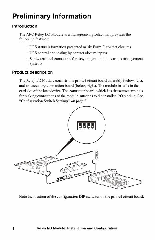
The Relay I/O Module consists of a printed circuit board assembly (below, left), and an accessory connection board (below, right). The module installs in the card slot of the host device. The connector board, which has the screw terminals for making connections to the module, attaches to the installed I/O module. See “Configuration Switch Settings” on page 6.
Note the location of the configuration DIP switches on the printed circuit board.
Relay I/O Module: Installation and Configuration1
990-0125.book Page 2 Friday, February 9, 2007 4:44 PM
Planning Your ConfigurationOperating considerations
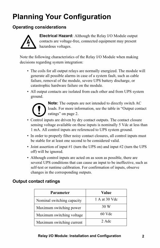
Electrical Hazard: Although the Relay I/O Module output contacts are voltage-free, connected equipment may present hazardous voltages.
Note the following characteristics of the Relay I/O Module when making decisions regarding system integration:
• The coils for all output relays are normally energized. The module will generate all possible alarms in case of a system fault, such as cable failure, removal of the module, severe UPS battery discharge, or catastrophic hardware failure on the module.
• All output contacts are isolated from each other and from UPS system ground.
Note: The outputs are not intended to directly switch AC loads. For more information, see the table in “Output contact ratings” on page 2.
• Control inputs are driven by dry contact outputs. The contact closure sensing voltage available on these inputs is nominally 5 Vdc at less than 1 mA. All control inputs are referenced to UPS system ground.
• In order to properly filter noisy contact closures, all control inputs must be stable for at least one second to be considered valid.
• Joint assertion of input #1 (turn the UPS on) and input #2 (turn the UPS off) will be ignored.
• Although control inputs are acted on as soon as possible, there are several UPS conditions that can cause an input to be ineffective, such as self-test or runtime calibration. For confirmation of inputs, observe changes in the corresponding outputs.
Output contact ratings
Parameter Value
Nominal switching capacity 1 A at 30 Vdc
Maximum switching power 30 W
Maximum switching voltage 60 Vdc
Maximum switching current 2 Adc
Relay I/O Module: Installation and Configuration 2
990-0125.book Page 3 Friday, February 9, 2007 4:44 PM
Relay I/O Module: Installation and Configuration3
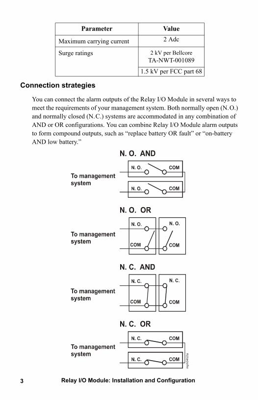
Connection strategies
You can connect the alarm outputs of the Relay I/O Module in several ways to meet the requirements of your management system. Both normally open (N.O.) and normally closed (N.C.) systems are accommodated in any combination of AND or OR configurations. You can combine Relay I/O Module alarm outputs to form compound outputs, such as “replace battery OR fault” or “on-battery AND low battery.”
Maximum carrying current 2 Adc
Surge ratings 2 kV per BellcoreTA-NWT-001089
1.5 kV per FCC part 68
Parameter Value
990-0125.book Page 4 Friday, February 9, 2007 4:44 PM
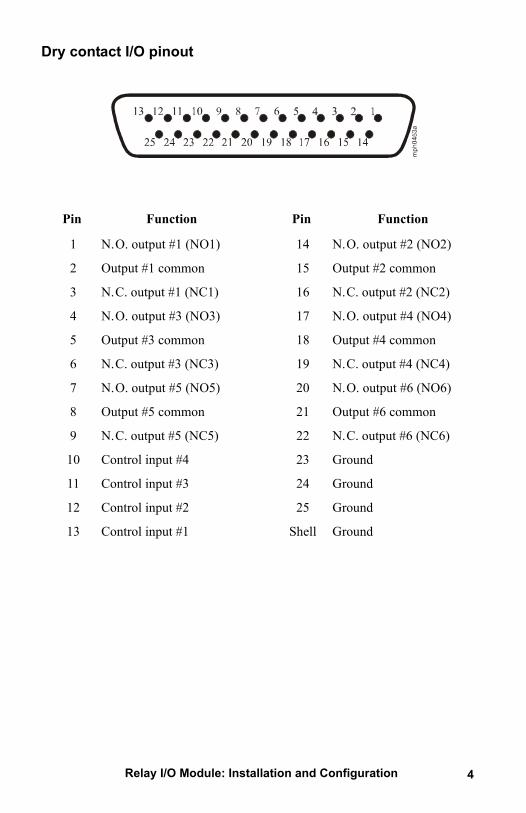
Dry contact I/O pinout
Pin Function Pin Function
1 N.O. output #1 (NO1) 14 N.O. output #2 (NO2)
2 Output #1 common 15 Output #2 common
3 N.C. output #1 (NC1) 16 N.C. output #2 (NC2)
4 N.O. output #3 (NO3) 17 N.O. output #4 (NO4)
5 Output #3 common 18 Output #4 common
6 N.C. output #3 (NC3) 19 N.C. output #4 (NC4)
7 N.O. output #5 (NO5) 20 N.O. output #6 (NO6)
8 Output #5 common 21 Output #6 common
9 N.C. output #5 (NC5) 22 N.C. output #6 (NC6)
10 Control input #4 23 Ground
11 Control input #3 24 Ground
12 Control input #2 25 Ground
13 Control input #1 Shell Ground
Relay I/O Module: Installation and Configuration 4
990-0125.book Page 5 Friday, February 9, 2007 4:44 PM
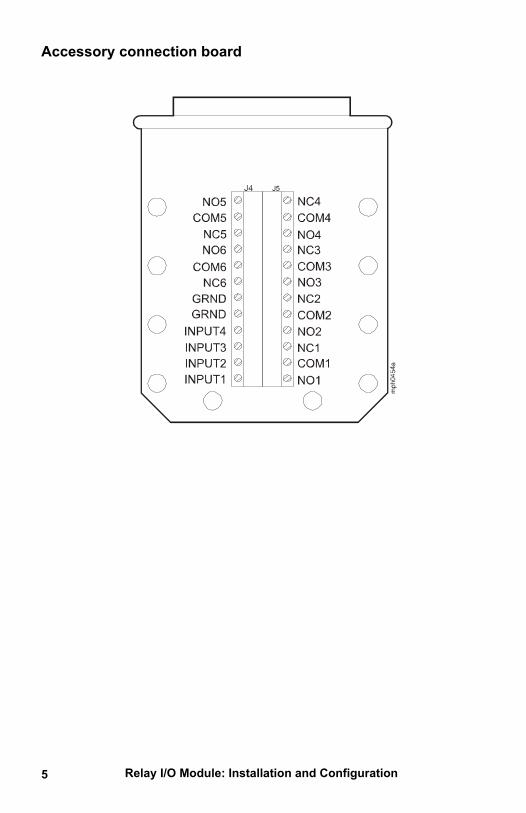
Accessory connection board
Relay I/O Module: Installation and Configuration5
990-0125.book Page 6 Friday, February 9, 2007 4:44 PM
Relay I/O Module: Installation and Configuration 6
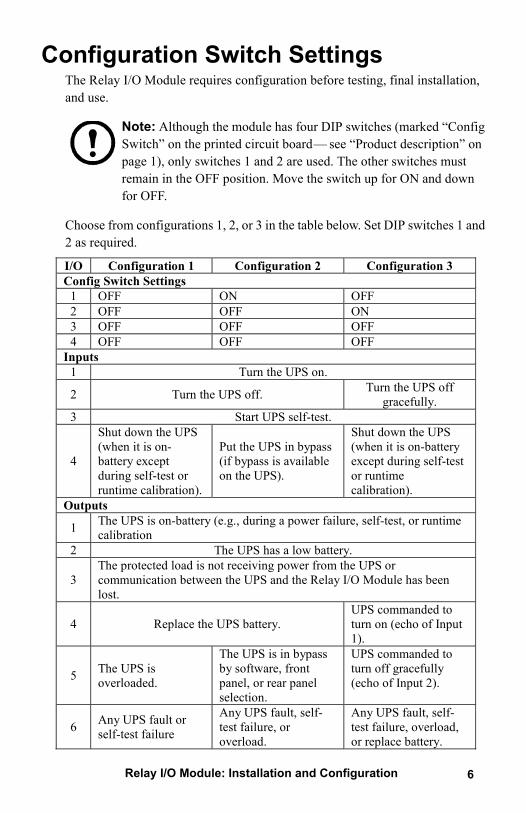
Configuration Switch SettingsThe Relay I/O Module requires configuration before testing, final installation, and use.
Note: Although the module has four DIP switches (marked “Config Switch” on the printed circuit board— see “Product description” on page 1), only switches 1 and 2 are used. The other switches must remain in the OFF position. Move the switch up for ON and down for OFF.
Choose from configurations 1, 2, or 3 in the table below. Set DIP switches 1 and 2 as required.
I/O Configuration 1 Configuration 2 Configuration 3 Config Switch Settings
1 OFF ON OFF 2 OFF OFF ON 3 OFF OFF OFF 4 OFF OFF OFF
Inputs 1 Turn the UPS on.
2 Turn the UPS off. Turn the UPS off gracefully.
3 Start UPS self-test.
4
Shut down the UPS (when it is on-battery except during self-test or runtime calibration).
Put the UPS in bypass (if bypass is available on the UPS).
Shut down the UPS (when it is on-battery except during self-test or runtime calibration).
Outputs
1 The UPS is on-battery (e.g., during a power failure, self-test, or runtime calibration
2 The UPS has a low battery.
3 The protected load is not receiving power from the UPS or communication between the UPS and the Relay I/O Module has been lost.
4 Replace the UPS battery. UPS commanded to turn on (echo of Input 1).
5 The UPS is overloaded.
The UPS is in bypass by software, front panel, or rear panel selection.
UPS commanded to turn off gracefully (echo of Input 2).
6 Any UPS fault or self-test failure
Any UPS fault, self-test failure, or overload.
Any UPS fault, self-test failure, overload, or replace battery.
990-0125.book Page 7 Friday, February 9, 2007 4:44 PM
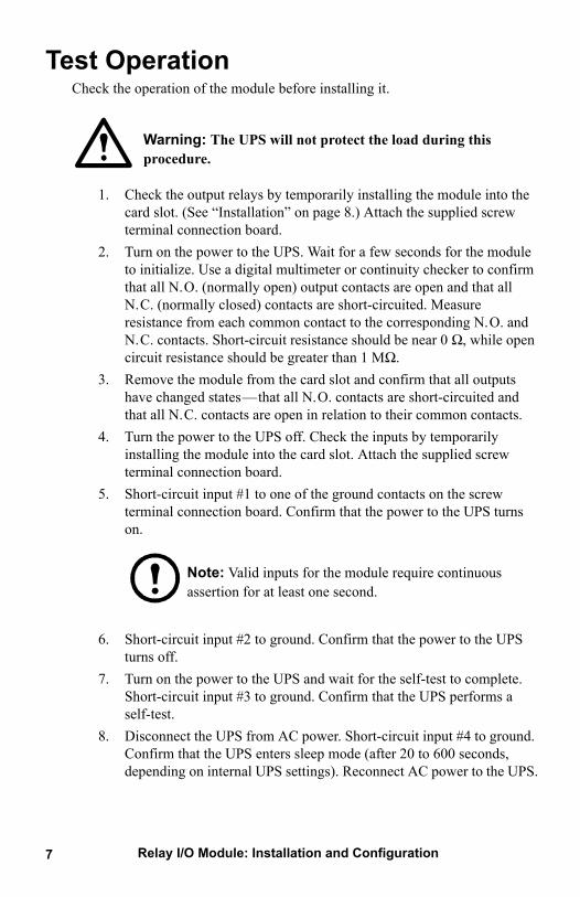
Test OperationCheck the operation of the module before installing it.
Warning: The UPS will not protect the load during this procedure.
1. Check the output relays by temporarily installing the module into the card slot. (See “Installation” on page 8.) Attach the supplied screw terminal connection board.
2. Turn on the power to the UPS. Wait for a few seconds for the module to initialize. Use a digital multimeter or continuity checker to confirm that all N.O. (normally open) output contacts are open and that all N.C. (normally closed) contacts are short-circuited. Measure resistance from each common contact to the corresponding N.O. and N.C. contacts. Short-circuit resistance should be near 0 Ω, while open circuit resistance should be greater than 1 MΩ.
3. Remove the module from the card slot and confirm that all outputs have changed states—that all N.O. contacts are short-circuited and that all N.C. contacts are open in relation to their common contacts.
4. Turn the power to the UPS off. Check the inputs by temporarily installing the module into the card slot. Attach the supplied screw terminal connection board.
5. Short-circuit input #1 to one of the ground contacts on the screw terminal connection board. Confirm that the power to the UPS turns on.
Note: Valid inputs for the module require continuous assertion for at least one second.
6. Short-circuit input #2 to ground. Confirm that the power to the UPS turns off.
7. Turn on the power to the UPS and wait for the self-test to complete. Short-circuit input #3 to ground. Confirm that the UPS performs a self-test.
8. Disconnect the UPS from AC power. Short-circuit input #4 to ground. Confirm that the UPS enters sleep mode (after 20 to 600 seconds, depending on internal UPS settings). Reconnect AC power to the UPS.
Relay I/O Module: Installation and Configuration7
990-0125.book Page 8 Friday, February 9, 2007 4:44 PM
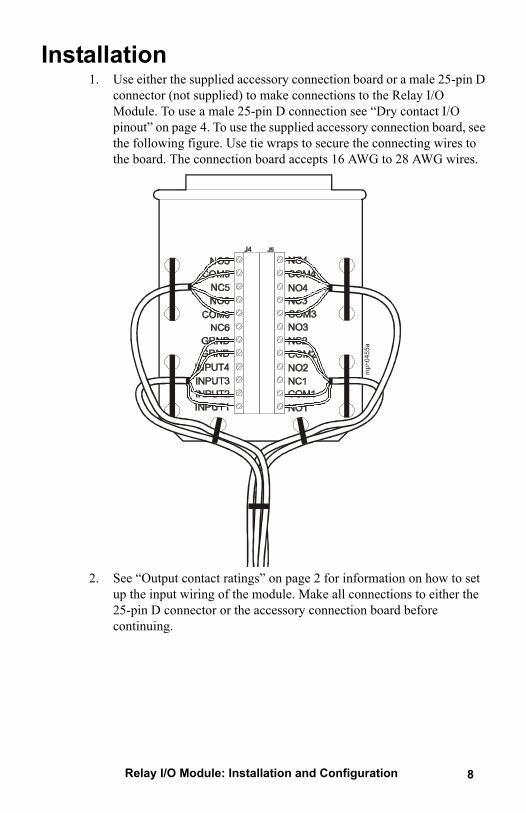
Installation1. Use either the supplied accessory connection board or a male 25-pin D
connector (not supplied) to make connections to the Relay I/O Module. To use a male 25-pin D connection see “Dry contact I/O pinout” on page 4. To use the supplied accessory connection board, see the following figure. Use tie wraps to secure the connecting wires to the board. The connection board accepts 16 AWG to 28 AWG wires.
2. See “Output contact ratings” on page 2 for information on how to set up the input wiring of the module. Make all connections to either the 25-pin D connector or the accessory connection board before continuing.
Relay I/O Module: Installation and Configuration 8
990-0125.book Page 9 Friday, February 9, 2007 4:44 PM
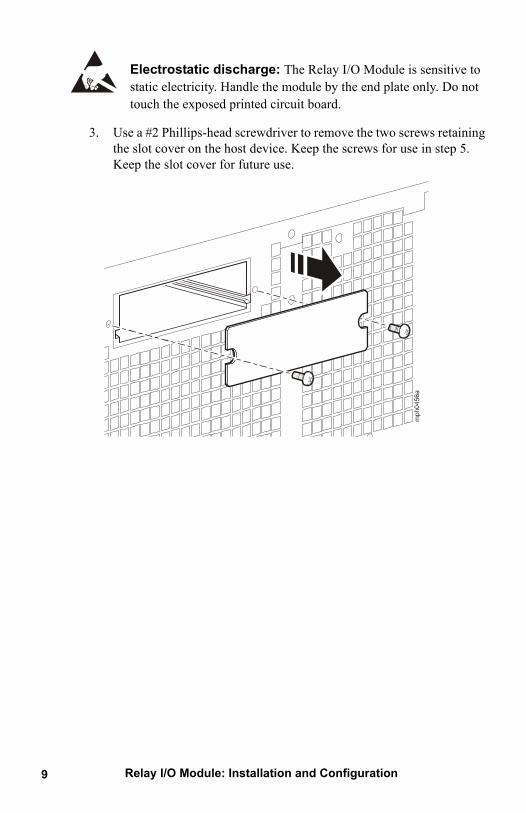
Electrostatic discharge: The Relay I/O Module is sensitive to static electricity. Handle the module by the end plate only. Do not touch the exposed printed circuit board.
3. Use a #2 Phillips-head screwdriver to remove the two screws retaining the slot cover on the host device. Keep the screws for use in step 5. Keep the slot cover for future use.
Relay I/O Module: Installation and Configuration9
990-0125.book Page 10 Friday, February 9, 2007 4:44 PM
Relay I/O Module: Installation and Configuration 10
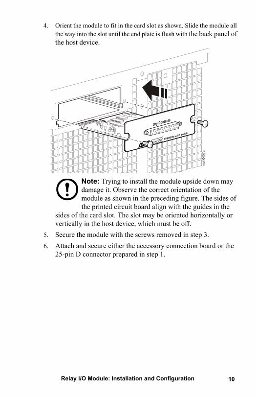
4. Orient the module to fit in the card slot as shown. Slide the module all the way into the slot until the end plate is flush with the back panel of the host device.
Note: Trying to install the module upside down may damage it. Observe the correct orientation of the module as shown in the preceding figure. The sides of the printed circuit board align with the guides in the
sides of the card slot. The slot may be oriented horizontally or vertically in the host device, which must be off.
5. Secure the module with the screws removed in step 3.6. Attach and secure either the accessory connection board or the
25-pin D connector prepared in step 1.
990-0125.book Page 11 Friday, February 9, 2007 4:44 PM
Relay I/O Module: Installation and Configuration11
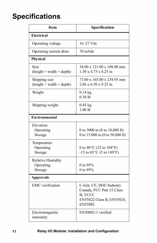
SpecificationsItem Specification
Electrical
Operating voltage 16–27 Vdc
Operating current draw 70 mAdc
Physical
Size (height × width × depth)
38.00 x 121.00 x 108.00 mm1.50 x 4.75 x 4.25 in
Shipping size(height × width × depth)
73.00 x 165.00 x 234.95 mm2.86 x 6.50 x 9.25 in
Weight 0.14 kg0.30 lb
Shipping weight 0.45 kg1.00 lb
Environmental
ElevationOperatingStorage
0 to 3000 m (0 to 10,000 ft) 0 to 15 000 m (0 to 50,000 ft)
TemperatureOperatingStorage
0 to 40°C (32 to 104°F)-15 to 65°C (5 to 149°F)
Relative HumidityOperatingStorage
0 to 95%0 to 95%
Approvals
EMC verification C-tick, CE, DOC/Industry Canada, FCC Part 15 Class B, VCCIEN55022 Class B, EN55024, EN55082
Electromagnetic immunity
EN50082-1 verified
990-0125.book Page 12 Friday, February 9, 2007 4:44 PM
Relay I/O Module: Installation and Configuration
Warranty Two-Year Factory Warranty
This warranty applies only to the products you purchase for your use in accordance with this manual.
Terms of warranty
APC warrants its products to be free from defects in materials and workmanship for a period of two years from the date of purchase. APC will repair or replace defective products covered by this warranty. This warranty does not apply to equipment that has been damaged by accident, negligence or misapplication or has been altered or modified in any way. Repair or replacement of a defective product or part thereof does not extend the original warranty period. Any parts furnished under this warranty may be new or factory-remanufactured.
Non-transferable warranty
This warranty extends only to the original purchaser who must have properly registered the product. The product may be registered at the APC Web site, www.apc.com.
Exclusions
APC shall not be liable under the warranty if its testing and examination disclose that the alleged defect in the product does not exist or was caused by end user’s or any third person’s misuse, negligence, improper installation or testing. Further, APC shall not be liable under the warranty for unauthorized attempts to repair or modify wrong or inadequate electrical voltage or connection, inappropriate on-site operation conditions, corrosive atmosphere, repair, installation, exposure to the elements, Acts of God, fire, theft, or installation contrary to APC recommendations or specifications or in any event if the APC serial number has been altered, defaced, or removed, or any other cause beyond the range of the intended use.
THERE ARE NO WARRANTIES, EXPRESS OR IMPLIED, BY OPERATION OF LAW OR OTHERWISE, OF PRODUCTS SOLD, SERVICED OR FURNISHED UNDER THIS AGREEMENT OR IN CONNECTION HEREWITH. APC DISCLAIMS ALL IMPLIED WARRANTIES OF MERCHANTABILITY, SATISFACTION AND FITNESS FOR A PARTICULAR PURPOSE. APC EXPRESS WARRANTIES WILL NOT BE ENLARGED, DIMINISHED, OR AFFECTED BY AND NO OBLIGATION OR LIABILITY WILL ARISE OUT OF, APC RENDERING OF TECHNICAL OR OTHER ADVICE
12
990-0125.book Page 13 Friday, February 9, 2007 4:44 PM
OR SERVICE IN CONNECTION WITH THE PRODUCTS. THE FOREGOING WARRANTIES AND REMEDIES ARE EXCLUSIVE AND IN LIEU OF ALL OTHER WARRANTIES AND REMEDIES. THE WARRANTIES SET FORTH ABOVE CONSTITUTE APC’S SOLE LIABILITY AND PURCHASER’S EXCLUSIVE REMEDY FOR ANY BREACH OF SUCH WARRANTIES. APC WARRANTIES EXTEND ONLY TO PURCHASER AND ARE NOT EXTENDED TO ANY THIRD PARTIES.
IN NO EVENT SHALL APC, ITS OFFICERS, DIRECTORS, AFFILIATES OR EMPLOYEES BE LIABLE FOR ANY FORM OF INDIRECT, SPECIAL, CONSEQUENTIAL OR PUNITIVE DAMAGES, ARISING OUT OF THE USE, SERVICE OR INSTALLATION, OF THE PRODUCTS, WHETHER SUCH DAMAGES ARISE IN CONTRACT OR TORT, IRRESPECTIVE OF FAULT, NEGLIGENCE OR STRICT LIABILITY OR WHETHER APC HAS BEEN ADVISED IN ADVANCE OF THE POSSIBILITY OF SUCH DAMAGES. SPECIFICALLY, APC IS NOT LIABLE FOR ANY COSTS, SUCH AS LOST PROFITS OR REVENUE, LOSS OF EQUIPMENT, LOSS OF USE OF EQUIPMENT, LOSS OF SOFTWARE, LOSS OF DATA, COSTS OF SUBSTITUENTS, CLAIMS BY THIRD PARTIES, OR OTHERWISE.
NO SALESMAN, EMPLOYEE OR AGENT OF APC IS AUTHORIZED TO ADD TO OR VARY THE TERMS OF THIS WARRANTY. WARRANTY TERMS MAY BE MODIFIED, IF AT ALL, ONLY IN WRITING SIGNED BY AN APC OFFICER AND LEGAL DEPARTMENT.
Warranty claims
Customers with warranty claims issues may access the APC customer support network through the Support page of the APC Web site, www.apc.com/support. Select your country from the country selection pull-down menu at the top of the Web page. Select the Support tab to obtain contact information for customer support in your region.
Relay I/O Module: Installation and Configuration13
990-0125.book Page 14 Friday, February 9, 2007 4:44 PM
Relay I/O Module: Installation and Configuration 14
Warranty ProceduresClaims
To obtain service under the warranty, contact APC Customer Support (see the back cover of this manual for contact information). You will need the model number of the Product, the serial number, and the date purchased. A technician will also ask you to describe the problem. If it is determined that the Product will need to be returned to APC, you must obtain a returned material authorization (RMA) number from APC Customer Support. Products that must be returned must have the RMA number marked on the outside of the package and must be returned with transportation charges prepaid. If it is determined by APC Customer Support that on-site repair of the Product is allowed, APC will arrange to have APC authorized service personnel dispatched to the Product location for repair or replacement, at the discretion of APC.
Parts
• APC warrants the parts of their systems for 1 year from the date of commissioning or 18 months from the ship date. This warranty only covers the cost of the part and not the labor for installation.
• Calls for warranty parts requests need to have specific unit information (serial number, model number, job number) to allow proper identification and processing of the warranty part transaction.
• A purchase order may be required to issue any warranty parts. An invoice will be sent once the parts are shipped to the field. You have 30 days to return the defective parts to APC. After 30 days, the warranty invoice will be outstanding, and payment of the invoice will be expected in full.
• Return authorization documentation will be sent with the replacement part. This documentation must be sent back with the defective part to APC for proper identification of the warranty return. Mark the warranty return number on the outside of the package.
• After the part has been received at APC, we will determine the status of the credit based on the findings of the returned part. Parts that are damaged from lack of maintenance, misapplication, improper installation, shipping damage, or acts of man/nature will not be covered under the parts warranty.
• Any warranty parts request received before 1:00 PM EST will be shipped same-day standard ground delivery. Any costs associated with Next Day or Airfreight will be the responsibility of the party requesting the part.
• Return freight of warranty parts to APC is the responsibility of the party returning the part.

990-0125.book Page 15 Friday, February 9, 2007 4:44 PM
Relay I/O Module: Installation and Configuration
Life-Support PolicyGeneral policy
American Power Conversion (APC) does not recommend the use of any of its products in the following situations:
• In life-support applications where failure or malfunction of the APC product can be reasonably expected to cause failure of the life-support device or to affect significantly its safety or effectiveness.
• In direct patient care.APC will not knowingly sell its products for use in such applications unless it receives in writing assurances satisfactory to APC that (a) the risks of injury or damage have been minimized, (b) the customer assumes all such risks, and (c) the liability of APC is adequately protected under the circumstances.
Examples of life support devices
The term life-support device includes but is not limited to neonatal oxygen analyzers, nerve stimulators (whether used for anesthesia, pain relief, or other purposes), autotransfusion devices, blood pumps, defibrillators, arrhythmia detectors and alarms, pacemakers, hemodialysis systems, peritoneal dialysis systems, neonatal ventilator incubators, ventilators (for adults and infants), anesthesia ventilators, infusion pumps, and any other devices designated as “critical” by the U.S. FDA.
Hospital-grade wiring devices and leakage current protection may be ordered as options on many APC UPS systems. APC does not claim that units with these modifications are certified or listed as hospital-grade by APC or any other organization. Therefore these units do not meet the requirements for use in direct patient care.
15
APC Worldwide Customer SupportCustomer support for this or any other APC product is available at no charge in any of the following ways:
• Visit the APC Web site to access documents in the APC Knowledge Base and to submit customer support requests.– www.apc.com (Corporate Headquarters)
Connect to localized APC Web sites for specific countries, each of which provides customer support information.
– www.apc.com/support/Global support searching APC Knowledge Base and using e-support.
• Contact an APC Customer Support center by telephone or e-mail.– Regional centers
– Local, country-specific centers: go to www.apc.com/support/contact for contact information.
Contact the APC representative or other distributor from whom you purchased your APC product for information on how to obtain local customer support.
Direct InfraStruXure Customer Support Line
(1)(877)537-0607 (toll free)
APC headquarters U.S., Canada
(1)(800)800-4272 (toll free)
Latin America (1)(401)789-5735 (USA)
Europe, Middle East, Africa
(353)(91)702000 (Ireland)
Japan (0) 35434-2021
Australia, New Zealand, South Pacific area
(61) (2) 9955 9366 (Australia)
02/2007990-0125B *990-0125B*
Entire contents copyright 2007 American Power Conversion Corporation. All rights reserved. Reproduction in whole or in part without permission is prohibited. APC, the APC logo, and
InfraStruXure are trademarks of American Power Conversion Corporation. All other trademarks, product names, and corporate names are the property of their respective owners and are used for informational
purposes only.
990-0125.book Page 2 Friday, February 9, 2007 4:44 PM