reinforcing bar couplers - ancon australia dia. (mm) 12-50 12-50 12-50 ... and enlarged by cold...
TRANSCRIPT
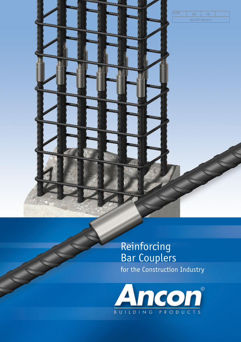
ReinforcingBar Couplersfor the Construction Industry
CI/SfB (29) Et6
May 2012 (Version 2)
2 Tel: 1300 304 320 www.ancon.com.au22 Tel: 1300 304 320 www.ancon.com.au
Ancon designs and manufactures high integrity steel products for
the construction industry. Through continuous programmes of
new product development, inward investment and employee
advancement, the company is committed to maintaining the
highest level of customer service within a dynamic and
challenging industry.
Masonry Support Systems
Windposts and Lintels
Wall Ties and Restraint Fixings
Channel and Bolt Fixings
Tension and Compression Systems
Stainless Steel Fabrications
Flooring and Formed Sections
Shear Load Connectors
Stainless Steel Reinforcement
Reinforcing Bar Couplers
Reinforcement Continuity Systems
Punching Shear Reinforcement
Precast Concrete Accessories
For many years the use of mechanicalcouplers to join reinforcing bars has beenregarded as a means of reducing the use oflong bars. Engineers and contractors nowrecognise the benefits of using couplers toaccelerate the speed of construction, increaseproductivity and simplify design details.
Coupler Selection 4-5BT Series 6-8Ancon Anchors 9MBT ET Series 10-11MBT Transition Series 12-13MBT Headed Anchors 14MBT Electric Wrench 15Other Ancon Products 15
3
4 Tel: 1300 304 320 www.ancon.com.au
Reinforcing Bar Couplers
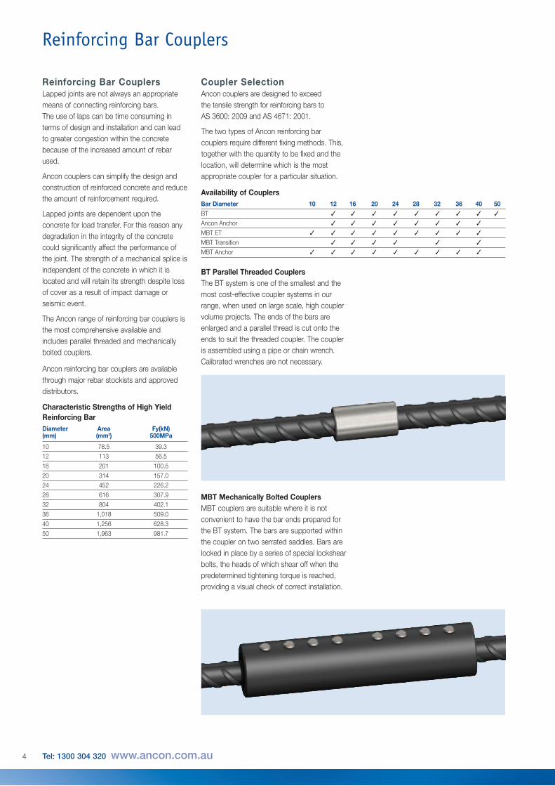
BT Parallel Threaded CouplersThe BT system is one of the smallest and themost cost-effective coupler systems in ourrange, when used on large scale, high couplervolume projects. The ends of the bars areenlarged and a parallel thread is cut onto theends to suit the threaded coupler. The coupleris assembled using a pipe or chain wrench.Calibrated wrenches are not necessary.
MBT Mechanically Bolted CouplersMBT couplers are suitable where it is notconvenient to have the bar ends prepared forthe BT system. The bars are supported withinthe coupler on two serrated saddles. Bars arelocked in place by a series of special lockshearbolts, the heads of which shear off when thepredetermined tightening torque is reached,providing a visual check of correct installation.
Coupler SelectionAncon couplers are designed to exceedthe tensile strength for reinforcing bars toAS 3600: 2009 and AS 4671: 2001.
The two types of Ancon reinforcing barcouplers require different fixing methods. This,together with the quantity to be fixed and thelocation, will determine which is the mostappropriate coupler for a particular situation.
Availability of CouplersBar Diameter 10 12 16 20 24 28 32 36 40 50 BT
Ancon Anchor
MBT ET
MBT Transition
MBT Anchor
✓ ✓ ✓ ✓ ✓ ✓ ✓ ✓ ✓
✓ ✓ ✓ ✓ ✓ ✓ ✓ ✓
✓ ✓ ✓ ✓ ✓ ✓ ✓ ✓ ✓
✓ ✓ ✓ ✓ ✓ ✓
✓ ✓ ✓ ✓ ✓ ✓ ✓ ✓ ✓
Reinforcing Bar CouplersLapped joints are not always an appropriatemeans of connecting reinforcing bars.The use of laps can be time consuming interms of design and installation and can leadto greater congestion within the concretebecause of the increased amount of rebarused.
Ancon couplers can simplify the design andconstruction of reinforced concrete and reducethe amount of reinforcement required.
Lapped joints are dependent upon theconcrete for load transfer. For this reason anydegradation in the integrity of the concretecould significantly affect the performance ofthe joint. The strength of a mechanical splice isindependent of the concrete in which it islocated and will retain its strength despite lossof cover as a result of impact damage orseismic event.
The Ancon range of reinforcing bar couplers isthe most comprehensive available andincludes parallel threaded and mechanicallybolted couplers.
Ancon reinforcing bar couplers are availablethrough major rebar stockists and approveddistributors.
Characteristic Strengths of High YieldReinforcing BarDiameter Area Fy(kN)(mm) (mm2) 500MPa
10 78.5 39.3
12 113 56.5
16 201 100.5
20 314 157.0
24 452 226.2
28 616 307.9
32 804 402.1
36 1,018 509.0
40 1,256 628.3
50 1,963 981.7
5
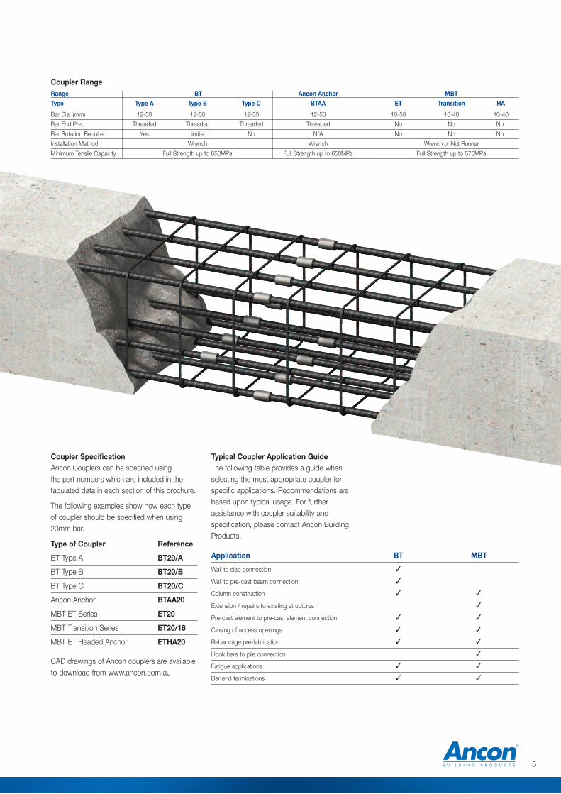
Range BT Ancon Anchor MBTType Type A Type B Type C BTAA ET Transition HA
Bar Dia. (mm) 12-50 12-50 12-50 12-50 10-50 10-40 10-40
Bar End Prep Threaded Threaded Threaded Threaded No No No
Bar Rotation Required Yes Limited No N/A No No No
Installation Method Wrench Wrench Wrench or Nut Runner
Minimum Tensile Capacity Full Strength up to 650MPa Full Strength up to 650MPa Full Strength up to 575MPa
Coupler SpecificationAncon Couplers can be specified using the part numbers which are included in thetabulated data in each section of this brochure.
The following examples show how each typeof coupler should be specified when using20mm bar.
Type of Coupler Reference
BT Type A BT20/A
BT Type B BT20/B
BT Type C BT20/C
Ancon Anchor BTAA20
MBT ET Series ET20
MBT Transition Series ET20/16
MBT ET Headed Anchor ETHA20
CAD drawings of Ancon couplers are availableto download from www.ancon.com.au
Typical Coupler Application GuideThe following table provides a guide whenselecting the most appropriate coupler forspecific applications. Recommendations arebased upon typical usage. For furtherassistance with coupler suitability andspecification, please contact Ancon BuildingProducts.
Application BT MBT
Wall to slab connection
Wall to pre-cast beam connection
Column construction
Extension / repairs to existing structures
Pre-cast element to pre-cast element connection
Closing of access openings
Rebar cage pre-fabrication
Hook bars to pile connection
Fatigue applications
Bar end terminations
✓
✓
✓ ✓
✓
✓ ✓
✓ ✓
✓ ✓
✓
✓ ✓
✓ ✓
Coupler Range
6 Tel: 1300 304 320 www.ancon.com.au
2tt
t
t2t
2/3 t2 2/3 t
2tt
2t
l
d
Reinforcing Bar Couplers
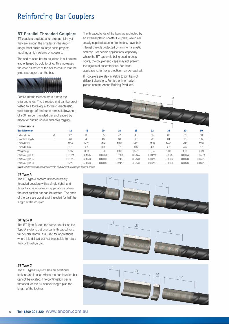
BT Parallel Threaded CouplersBT couplers produce a full strength joint yetthey are among the smallest in the Anconrange, best suited to large scale projectsrequiring a high volume of couplers.
The end of each bar to be joined is cut squareand enlarged by cold forging. This increasesthe core diameter of the bar to ensure that thejoint is stronger than the bar.
Parallel metric threads are cut onto theenlarged ends. The threaded end can be prooftested to a force equal to the characteristicyield strength of the bar. A nominal allowanceof +50mm per threaded bar end should bemade for cutting square and cold forging.
The threaded ends of the bars are protected byan external plastic sheath. Couplers, which areusually supplied attached to the bar, have theirinternal threads protected by an internal plasticend cap. For certain applications, especiallywhere the BT system is being used in deeppours, the coupler end caps may not preventthe ingress of concrete fines. For theseapplications, further protection may be required.
BT couplers are also available to join bars ofdifferent diameters. For further informationplease contact Ancon Building Products.
BT Type BThe BT Type B uses the same coupler as theType A system, but one bar is threaded for afull coupler length. It is used for applicationswhere it is difficult but not impossible to rotatethe continuation bar.
BT Type CThe BT Type C system has an additionallocknut and is used where the continuation barcannot be rotated. The continuation bar isthreaded for the full coupler length plus thelength of the locknut.
BT Type AThe BT Type A system utilises internallythreaded couplers with a single right handthread and is suitable for applications wherethe continuation bar can be rotated. The endsof the bars are upset and threaded for half thelength of the coupler.
Bar Diameter 12 16 20 24 28 32 36 40 50
External Dia. d 22 30 35 42 48 55 60 65 80
Coupler Length l 28 40 48 60 66 72 84 90 112
Thread Size M14 M20 M24 M30 M33 M36 M42 M45 M56
Thread Pitch 2.0 2.5 3.0 3.5 3.5 4.0 4.5 4.5 5.5
Weight (kg) 0.05 0.14 0.20 0.36 0.55 0.84 1.06 1.35 2.49
Part No Type A BT12/A BT16/A BT20/A BT24/A BT28/A BT32/A BT36/A BT40/A BT50/A
Part No Type B BT12/B BT16/B BT20/B BT24/B BT28/B BT32/B BT36/B BT40/B BT50/B
Part No Type C N/A BT16/C BT20/C BT24/C BT28/C BT32/C BT36/C BT40/C BT50/C
Note: All dimensions are approximate and subject to change without notice.
Dimensions
7
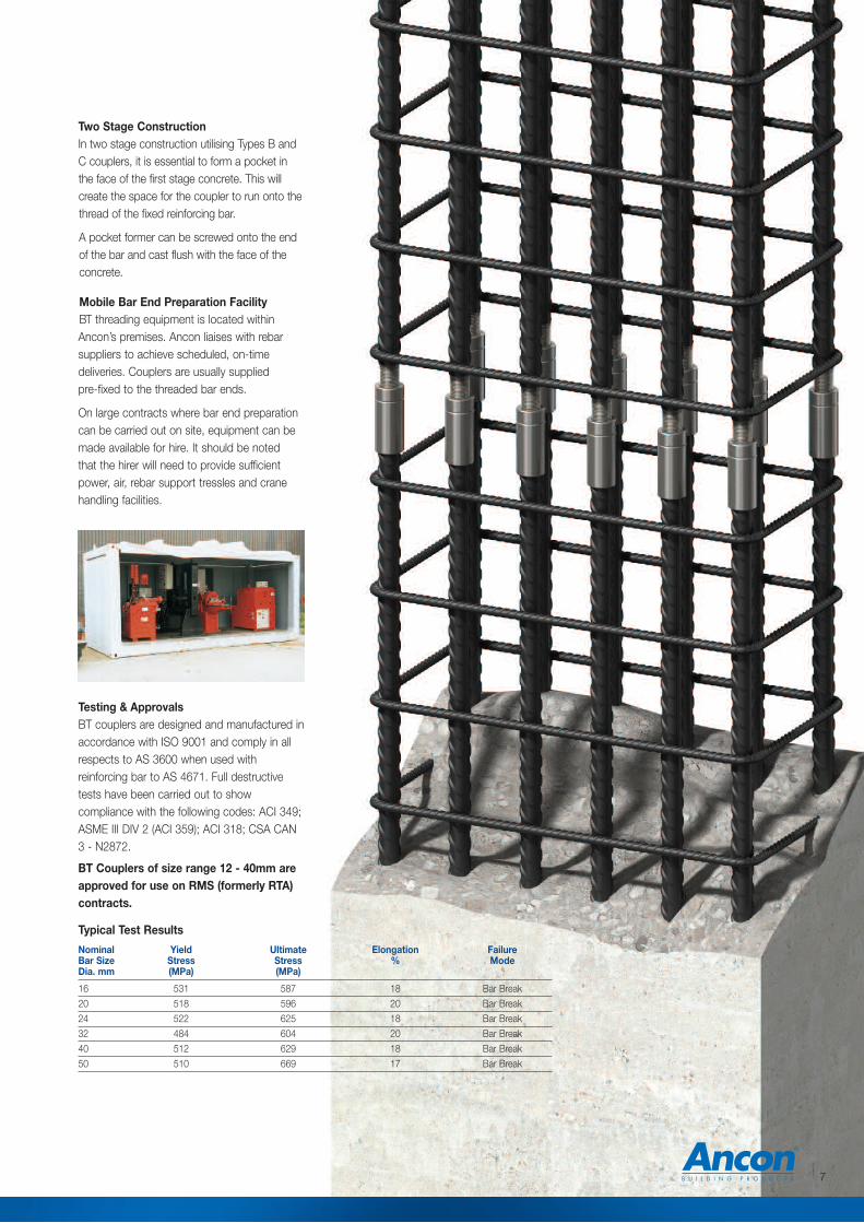
Nominal Yield Ultimate Elongation FailureBar Size Stress Stress % ModeDia. mm (MPa) (MPa)
16 531 587 18 Bar Break
20 518 596 20 Bar Break
24 522 625 18 Bar Break
32 484 604 20 Bar Break
40 512 629 18 Bar Break
50 510 669 17 Bar Break
Two Stage ConstructionIn two stage construction utilising Types B andC couplers, it is essential to form a pocket inthe face of the first stage concrete. This willcreate the space for the coupler to run onto thethread of the fixed reinforcing bar.
A pocket former can be screwed onto the endof the bar and cast flush with the face of theconcrete.
Mobile Bar End Preparation FacilityBT threading equipment is located withinAncon’s premises. Ancon liaises with rebarsuppliers to achieve scheduled, on-timedeliveries. Couplers are usually supplied pre-fixed to the threaded bar ends.
On large contracts where bar end preparationcan be carried out on site, equipment can bemade available for hire. It should be noted that the hirer will need to provide sufficientpower, air, rebar support tressles and cranehandling facilities.
Testing & ApprovalsBT couplers are designed and manufactured inaccordance with ISO 9001 and comply in allrespects to AS 3600 when used withreinforcing bar to AS 4671. Full destructivetests have been carried out to showcompliance with the following codes: ACI 349;ASME III DIV 2 (ACI 359); ACI 318; CSA CAN3 - N2872.
BT Couplers of size range 12 - 40mm areapproved for use on RMS (formerly RTA)contracts.
Typical Test Results
8 Tel: 1300 304 320 www.ancon.com.au
Reinforcing Bar Couplers
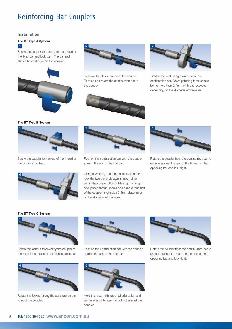
Installation
The BT Type A System
Position the continuation bar with the coupler against the end of the first bar.
Rotate the coupler from the continuation bar toengage against the rear of the thread on theopposing bar and lock tight.
2 3
The BT Type B System
Screw the coupler to the rear of the thread onthe continuation bar.
1
Using a wrench, rotate the continuation bar tolock the two bar ends against each otherwithin the coupler. After tightening, the lengthof exposed thread should be no more than halfof the coupler length plus 2-4mm dependingon the diameter of the rebar.
4
Screw the coupler to the rear of the thread onthe fixed bar and lock tight. The bar endshould be central within the coupler.
1
Remove the plastic cap from the coupler.Position and rotate the continuation bar in the coupler.
Tighten the joint using a wrench on thecontinuation bar. After tightening there shouldbe no more than 2-4mm of thread exposed,depending on the diameter of the rebar.
2 3
4
Rotate the locknut along the continuation barto abut the coupler.
Hold the rebar in its required orientation andwith a wrench tighten the locknut against thecoupler.
5
Position the continuation bar with the coupler against the end of the first bar.
Rotate the coupler from the continuation bar toengage against the rear of the thread on theopposing bar and lock tight.
2 3
The BT Type C System
Screw the locknut followed by the coupler tothe rear of the thread on the continuation bar.
1
9
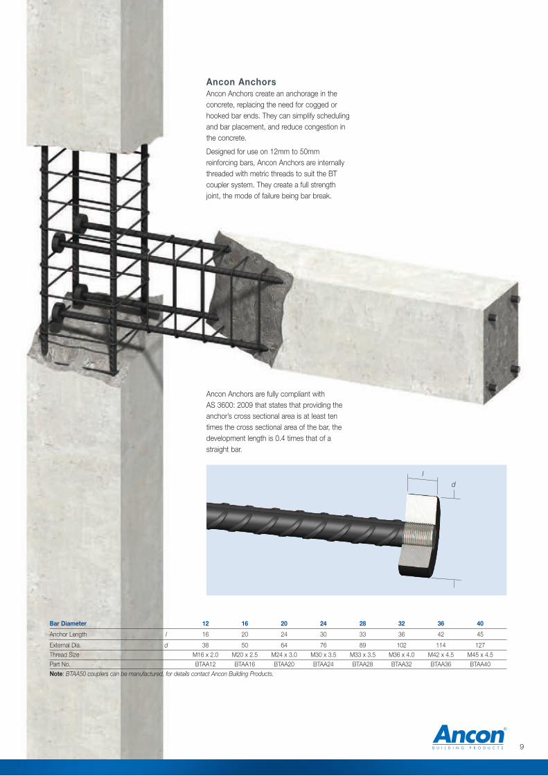
Bar Diameter 12 16 20 24 28 32 36 40
Anchor Length l 16 20 24 30 33 36 42 45
External Dia. d 38 50 64 76 89 102 114 127
Thread Size M16 x 2.0 M20 x 2.5 M24 x 3.0 M30 x 3.5 M33 x 3.5 M36 x 4.0 M42 x 4.5 M45 x 4.5
Part No. BTAA12 BTAA16 BTAA20 BTAA24 BTAA28 BTAA32 BTAA36 BTAA40
Note: BTAA50 couplers can be manufactured, for details contact Ancon Building Products.
ld
Ancon AnchorsAncon Anchors create an anchorage in theconcrete, replacing the need for cogged orhooked bar ends. They can simplify schedulingand bar placement, and reduce congestion inthe concrete.
Designed for use on 12mm to 50mmreinforcing bars, Ancon Anchors are internallythreaded with metric threads to suit the BTcoupler system. They create a full strengthjoint, the mode of failure being bar break.
Ancon Anchors are fully compliant with AS 3600: 2009 that states that providing theanchor’s cross sectional area is at least tentimes the cross sectional area of the bar, thedevelopment length is 0.4 times that of astraight bar.
10 Tel: 1300 304 320 www.ancon.com.au
Reinforcing Bar Couplers
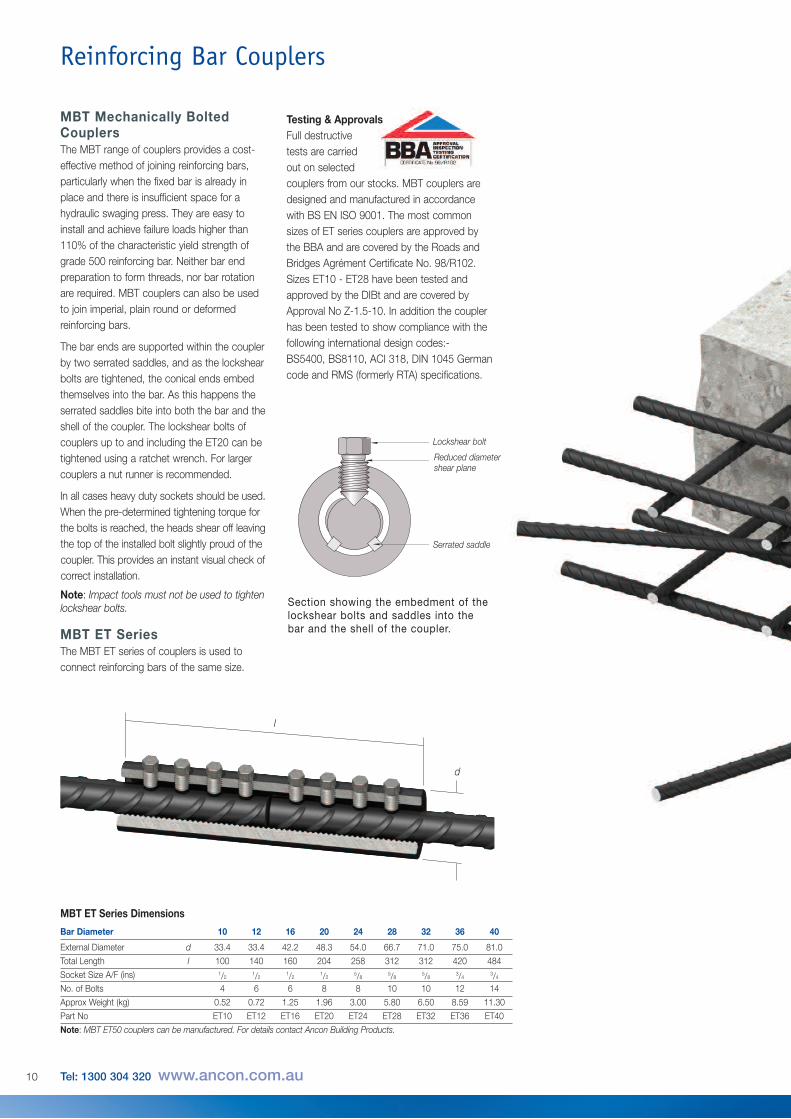
MBT Mechanically BoltedCouplersThe MBT range of couplers provides a cost-effective method of joining reinforcing bars,particularly when the fixed bar is already inplace and there is insufficient space for ahydraulic swaging press. They are easy toinstall and achieve failure loads higher than110% of the characteristic yield strength ofgrade 500 reinforcing bar. Neither bar endpreparation to form threads, nor bar rotationare required. MBT couplers can also be usedto join imperial, plain round or deformedreinforcing bars.
The bar ends are supported within the couplerby two serrated saddles, and as the lockshearbolts are tightened, the conical ends embedthemselves into the bar. As this happens theserrated saddles bite into both the bar and theshell of the coupler. The lockshear bolts ofcouplers up to and including the ET20 can betightened using a ratchet wrench. For largercouplers a nut runner is recommended.
In all cases heavy duty sockets should be used.When the pre-determined tightening torque forthe bolts is reached, the heads shear off leavingthe top of the installed bolt slightly proud of thecoupler. This provides an instant visual check ofcorrect installation.
Note: Impact tools must not be used to tightenlockshear bolts.
MBT ET SeriesThe MBT ET series of couplers is used toconnect reinforcing bars of the same size.
MBT ET Series Dimensions
Bar Diameter 10 12 16 20 24 28 32 36 40
External Diameter d 33.4 33.4 42.2 48.3 54.0 66.7 71.0 75.0 81.0
Total Length l 100 140 160 204 258 312 312 420 484
Socket Size A/F (ins) 1/2 1/2 1/2 1/2 5/8 5/8 5/8 3/4 3/4No. of Bolts 4 6 6 8 8 10 10 12 14
Approx Weight (kg) 0.52 0.72 1.25 1.96 3.00 5.80 6.50 8.59 11.30
Part No ET10 ET12 ET16 ET20 ET24 ET28 ET32 ET36 ET40
Note: MBT ET50 couplers can be manufactured. For details contact Ancon Building Products.
Testing & ApprovalsFull destructivetests are carriedout on selectedcouplers from our stocks. MBT couplers aredesigned and manufactured in accordancewith BS EN ISO 9001. The most commonsizes of ET series couplers are approved bythe BBA and are covered by the Roads andBridges Agrément Certificate No. 98/R102.Sizes ET10 - ET28 have been tested andapproved by the DIBt and are covered byApproval No Z-1.5-10. In addition the couplerhas been tested to show compliance with thefollowing international design codes:-BS5400, BS8110, ACI 318, DIN 1045 Germancode and RMS (formerly RTA) specifications.
Section showing the embedment of thelockshear bolts and saddles into thebar and the shell of the coupler.
Lockshear bolt
Reduced diametershear plane
Serrated saddle
l
d
11
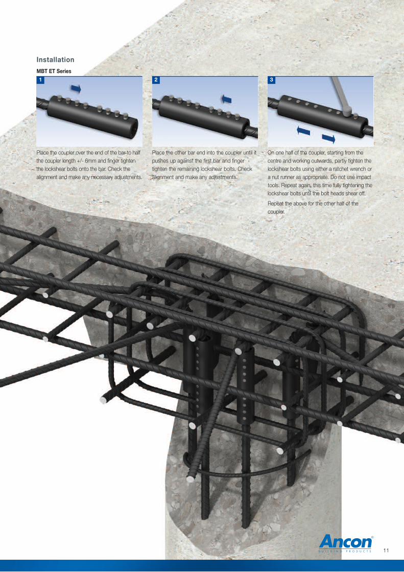
Place the other bar end into the coupler until itpushes up against the first bar and fingertighten the remaining lockshear bolts. Checkalignment and make any adjustments.
On one half of the coupler, starting from thecentre and working outwards, partly tighten thelockshear bolts using either a ratchet wrench ora nut runner as appropriate. Do not use impacttools. Repeat again, this time fully tightening thelockshear bolts until the bolt heads shear off.
Repeat the above for the other half of thecoupler.
2 3
Installation
MBT ET Series
Place the coupler over the end of the bar to halfthe coupler length +/- 6mm and finger tightenthe lockshear bolts onto the bar. Check thealignment and make any necessary adjustments.
1
12 Tel: 1300 304 320 www.ancon.com.au
a
d
b
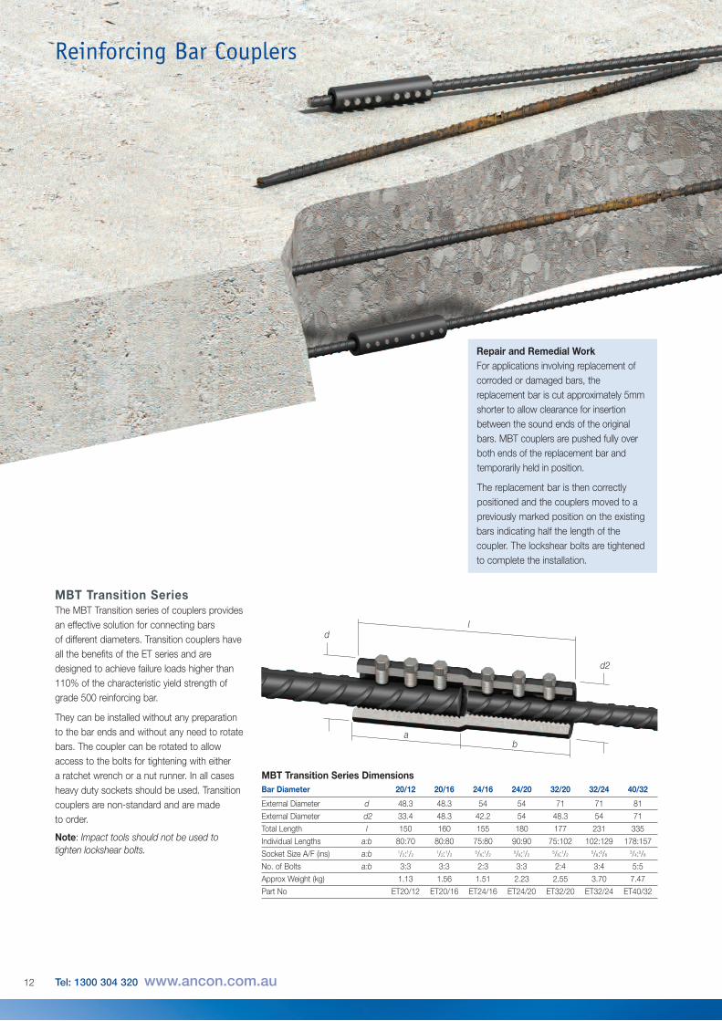
MBT Transition SeriesThe MBT Transition series of couplers providesan effective solution for connecting barsof different diameters. Transition couplers haveall the benefits of the ET series and aredesigned to achieve failure loads higher than110% of the characteristic yield strength ofgrade 500 reinforcing bar.
They can be installed without any preparationto the bar ends and without any need to rotatebars. The coupler can be rotated to allowaccess to the bolts for tightening with either a ratchet wrench or a nut runner. In all casesheavy duty sockets should be used. Transitioncouplers are non-standard and are made to order.
Note: Impact tools should not be used totighten lockshear bolts.
Bar Diameter 20/12 20/16 24/16 24/20 32/20 32/24 40/32
External Diameter d 48.3 48.3 54 54 71 71 81
External Diameter d2 33.4 48.3 42.2 54 48.3 54 71
Total Length l 150 160 155 180 177 231 335
Individual Lengths a:b 80:70 80:80 75:80 90:90 75:102 102:129 178:157
Socket Size A/F (ins) a:b 1/2:1/2 1/2:1/2 5/8:1/2 5/8:1/2 5/8:1/2 5/8:5/8 3/4:5/8
No. of Bolts a:b 3:3 3:3 2:3 3:3 2:4 3:4 5:5
Approx Weight (kg) 1.13 1.56 1.51 2.23 2.55 3.70 7.47
Part No ET20/12 ET20/16 ET24/16 ET24/20 ET32/20 ET32/24 ET40/32
MBT Transition Series Dimensions
Reinforcing Bar Couplers
Repair and Remedial WorkFor applications involving replacement ofcorroded or damaged bars, thereplacement bar is cut approximately 5mmshorter to allow clearance for insertionbetween the sound ends of the originalbars. MBT couplers are pushed fully overboth ends of the replacement bar andtemporarily held in position.
The replacement bar is then correctlypositioned and the couplers moved to apreviously marked position on the existingbars indicating half the length of thecoupler. The lockshear bolts are tightenedto complete the installation.
l
d2
13
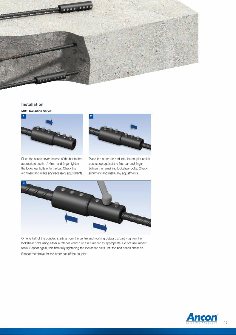
Place the other bar end into the coupler until itpushes up against the first bar and fingertighten the remaining lockshear bolts. Checkalignment and make any adjustments.
2
Installation
MBT Transition Series
Place the coupler over the end of the bar to theappropriate depth +/- 6mm and finger tightenthe lockshear bolts onto the bar. Check thealignment and make any necessary adjustments.
1
On one half of the coupler, starting from the centre and working outwards, partly tighten thelockshear bolts using either a ratchet wrench or a nut runner as appropriate. Do not use impacttools. Repeat again, this time fully tightening the lockshear bolts until the bolt heads shear off.
Repeat the above for the other half of the coupler
3
14 Tel: 1300 304 320 www.ancon.com.au
lo
l
t
p
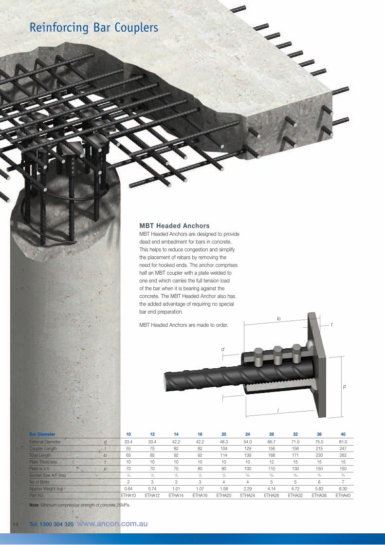
MBT Headed AnchorsMBT Headed Anchors are designed to providedead end embedment for bars in concrete.This helps to reduce congestion and simplifythe placement of rebars by removing the need for hooked ends. The anchor compriseshalf an MBT coupler with a plate welded toone end which carries the full tension load of the bar when it is bearing against theconcrete. The MBT Headed Anchor also hasthe added advantage of requiring no specialbar end preparation.
MBT Headed Anchors are made to order.
Bar Diameter 10 12 14 16 20 24 28 32 36 40
External Diameter d 33.4 33.4 42.2 42.2 48.3 54.0 66.7 71.0 75.0 81.0
Coupler Length l 55 75 82 82 104 129 156 156 215 247
Total Length lo 65 85 92 92 114 139 168 171 230 262
Plate Thickness t 10 10 10 10 10 10 12 15 15 15
Plate w x h p 70 70 70 80 90 100 110 130 150 150
Socket Size A/F (ins) 1/2 1/2 1/2 1/2 1/2 5/8 5/8 5/8 3/4 3/4
No of Bolts 2 3 3 3 4 4 5 5 6 7
Approx Weight (kg) 0.64 0.74 1.01 1.07 1.58 2.29 4.14 4.72 5.83 8.30
Part No. ETHA10 ETHA12 ETHA14 ETHA16 ETHA20 ETHA24 ETHA28 ETHA32 ETHA36 ETHA40
Note: Minimum compressive strength of concrete 25MPa.
Reinforcing Bar Couplers
d
15
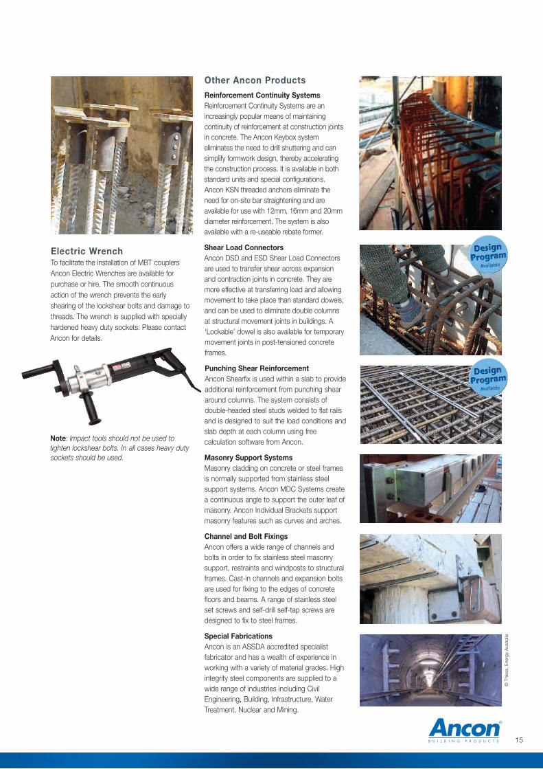
Other Ancon Products
Reinforcement Continuity SystemsReinforcement Continuity Systems are anincreasingly popular means of maintainingcontinuity of reinforcement at construction jointsin concrete. The Ancon Keybox systemeliminates the need to drill shuttering and cansimplify formwork design, thereby acceleratingthe construction process. It is available in bothstandard units and special configurations.Ancon KSN threaded anchors eliminate theneed for o n-site bar straightening and areavailable for use with 12mm, 16mm and 20mmdiameter reinforcement. The system is alsoavailable with a re-useable rebate former.
Shear Load ConnectorsAncon DSD and ESD Shear Load Connectorsare used to transfer shear across expansionand contraction joints in concrete. They aremore effective at transferring load and allowingmovement to take place than standard dowels,and can be used to eliminate double columnsat structural movement joints in buildings. A‘Lockable’ dowel is also available for temporarymovement joints in post-tensioned concreteframes.
Punching Shear ReinforcementAncon Shearfix is used within a slab to provideadditional reinforcement from punching sheararound columns. The system consists ofdouble-headed steel studs welded to flat railsand is designed to suit the load conditions andslab depth at each column using freecalculation software from Ancon.
Masonry Support SystemsMasonry cladding on concrete or steel framesis normally supported from stainless steelsupport systems. Ancon MDC Systems createa continuous angle to support the outer leaf ofmasonry. Ancon Individual Brackets supportmasonry features such as curves and arches.
Channel and Bolt FixingsAncon offers a wide range of channels andbolts in order to fix stainless steel masonrysupport, restraints and windposts to structuralframes. Cast-in channels and expansion boltsare used for fixing to the edges of concretefloors and beams. A range of stainless steelset screws and self-drill self-tap screws aredesigned to fix to steel frames.
Special FabricationsAncon is an ASSDA accredited specialistfabricator and has a wealth of experience inworking with a variety of material grades. Highintegrity steel components are supplied to awide range of industries including CivilEngineering, Building, Infrastructure, WaterTreatment, Nuclear and Mining.
Electric Wrench To facilitate the installation of MBT couplersAncon Electric Wrenches are available forpurchase or hire. The smooth continuousaction of the wrench prevents the earlyshearing of the lockshear bolts and damage tothreads. The wrench is supplied with speciallyhardened heavy duty sockets. Please contactAncon for details.
Note: Impact tools should not be used totighten lockshear bolts. In all cases heavy dutysockets should be used.
© Thiess, Ene
rgy Australia
© Ancon Building Products 2012
The construction applications and details provided in this literatureare indicative only. In every case, project working details should beentrusted to appropriately qualified and experienced persons.
Whilst every care has been exercised in the preparation of thisdocument to ensure that any advice, recommendations orinformation is accurate, no liability or responsibility of any kind isaccepted in respect of Ancon Building Products.
With a policy of continuous product development Ancon BuildingProducts reserves the right to modify product design andspecification without due notice.
These products are available from:
Masonry Support Systems
Windposts and Lintels
Wall Ties and Restraint Fixings
Channel and Bolt Fixings
Tension and Compression Systems
Stainless Steel Fabrications
Flooring and Formed Sections
Shear Load Connectors
Stainless Steel Reinforcement
Reinforcing Bar Couplers
Reinforcement Continuity Systems
Punching Shear Reinforcement
Precast Concrete Accessories
Ancon Building Products7-9 Second AvenueSunshineMelbourneVIC 3020Tel: 1300 304 320Fax: +61 (0) 3 9311 1777
Ancon Building Products18 Tennant StreetWelshpoolPerthWA 6105Tel: 1300 304 320Fax: +61 (0) 8 9453 2300
Ancon Building Products2/19 Nuttall DriveHillsboroughChristchurch 8022Tel: +64 (0) 3 376 5205Fax: +64 (0) 3 376 5206
Ancon Building Products98 Kurrajong AvenueMount DruittSydneyNSW 2770Tel: 1300 304 320Fax: +61 (0) 2 9675 3390
Ancon Building Products4/15 Terrace PlaceMurarrieBrisbaneQLD 4172Tel: 1300 304 320Fax: +61 (0) 7 3395 6693
Email: [email protected]: www.ancon.com.auInternational Enquiries: +61 (0) 2 8808 3100
Overseas Offices:
Ancon Building ProductsSheffieldUnited Kingdomwww.ancon.co.uk
Ancon Building Products GesmbHViennaAustriawww.ancon.at
Ancon (Schweiz) AGRied bei KerzersSwitzerlandwww.ancon.ch
Ancon GmbHNurembergGermanywww.anconbp.de
Ancon (Middle East) FZEDubaiUnited Arab Emirateswww.ancon.ae
AUSTRALIAN NEW ZEALAND