reinforcement works for the slope … et al_ism milano 2012.pdfreinforcement works for the slope...
TRANSCRIPT

1
REINFORCEMENT WORKS FOR THE SLOPE STABILIZATION: STANDARD AND NEW APPROACHES FOR THE USE OF MICROPILES AND ANCHORS
Cola Simonetta1, Bisson Alberto1, Pilati Corrado2, Frasson Stefano2, Stevan Giovanni3,
Tessari Giulia3
ABSTRACT
The reinforcement works for the slope stabilization, natural or excavated slopes
in rocks or soils, have developed in various directions. The technology is always researching new solutions for reducing the economic and environmental impacts and, at the same time, guaranteeing efficiency and the maximum improvement of long-term safety conditions.
After a brief overview of the reinforcement types most commonly used in our region, with particular care to the Vicenza Province (NE Italy), the paper present a short discussion on their most favorable applicability conditions and on their efficiency.
Then we present a new approach for using the soil nailing in the stabilization of medium deep landslides, analyzing the advantages offered by this new solutions, namely “flexible belt” or “floating reinforcements”, in comparison with micropile structures and traditional anchors.
Finally, the paper introduces the studies recently started for improving the use of soil nailing as slope remedial works. 1. INTRODUCTION
The Vicenza Province, located in the Veneto Region (NE Italy), can be sub-
divided into two geological domains separated by the main tectonic lineaments (Figure 1). One domain is characterized by elevations up to 700 m a.s.l. and low slope angles: the outcrops are volcanic rocks (lavas, pyroclastites and ignimbrites) overlain by eluvial and colluvial deposits of variable thickness. Numerous rainfall-induced landslides, mainly shallow soil slips, flows and rotational and translational slides, affect this domain: overall, the landslides here located represent more than 80% of slope movements in the Province. The other domain has elevations up to 1900 m a.s.l. and medium to high slope angles. Here the outcropping rocks are limestones and dolomite, affected by falls, topples, deep and complex mass movements: here, the landslides represent less than 20% of the total landslides in the area.
To give an idea of the high frequency of landslides interesting this province, we remember what happened during the last exceptional rainfall event in November 2010 (Floris et al. 2011). In two days, about 340 mm of rain fell on the area causing one of the most catastrophic floods in the last 100 years in the pre-Alps and piedmont sectors
1 Prof.Eng. Simonetta Cola and Dr.Eng. Alberto Bisson, Depart. ICEA, University of Padova, Via Ognissanti 39, 35129 I Padova – Italy - 0039 49827- 7900 (tel) – 7988 (fax), [email protected]. 2 Dr.Eng. Corrado Pilati and Dr.Eng. Stefano Frasson, Geosoluzioni Engineering s.r.l., Viale dell'Industria,
Vicenza. 3 Dr.Eng. Giovanni Stevan and Dr.Eng. Giulia Tessari, Soil Protection Division, Vicenza Province, Italy.

2
of Veneto Region. The intense rainfall triggered a huge number of mass movements in the Northern and Western parts of the Vicenza Province: the Soil Protection Division (SPD) received about 500 warnings of landslides, distributed over 20 municipalities of the Vicenza Province (Figure 2).
In order to determine the priority of intervention, after a field survey in the affected areas, the SPD realized a simplified landslide database, collecting, for each movement, data on geographical location, event date and time, kinematics, involved rocks, state of activity and, finally, resulting and potential damages.
As reported in Figure 2, all types of landslides occurred with a prevalention of rotational slides (49%) and flow phenomena (soil slip, earth flow and debris flow). The phenomena, both localized and widespread, involved only the debris cover in 70% of cases, the eluvial or colluvial layer in 28% and the rock formations in the remaining 2% of cases. The majority of phenomena had small to medium size, 46% and 36% respectively, and only the 4% of them were very large landslides. The 89% of mass movements caused damages to the road system, while in the 7% of cases private buildings were involved. The overall estimated costs for remediation works amount to about 80 millions of Euro.
Since the SPD has the job of managing the design and the execution of landslide remedial works, it has widespread experience in this particular sector of geotechnical engineering. Moreover, the SPD concerns itself with research of new technical solutions
Figure 1. Geological map of Vicenza Province and landslide distribution in the area.

3
in order to reduce the cost and the impact of interventions, increasing, at the same time, their efficiency on the short and long-term global slope stability.
Consequently, on the base of the experience gained by the SPD, here we present a comparison among some different reinforcing works usually realized in order to remedy the damages due to movements and improve the stability of slopes affected by landslide risk. Herein, we limit our overview to the reinforcement techniques, even if, in this region, it is common to realize also drainage systems, installed singularly or coupled with reinforcements. This choice is due to our aim to develop an evaluation of the advantages offered in this engineering sector by a new solution adopting the soil nailing for slope stabilization also on medium/large landslides.
2. TYPICAL REINFORCEMENT INTERVENTION ON SLOPE
Slope stabilization with reinforcements provides to increase shear strength or
reduce the sliding actions along the slip surface with various types of structures: retaining walls, dowels, micropile systems, anchors, soil nailing, etc.
In Vicenza Province all kinds of wall are used: gravity or cantilever walls, gabion walls, reinforced earth walls and tied-back walls. As showed in Figure 3, the wall are used for stabilizing small size landslides, in slope regarding intervention, sometime coupled with a dewatering system (Ferrari, 2011).
Landslide type distribution
Landslide size distribution
Figure 2. Distribution of landslides occurred after October 31 – November 2, 2010, event.

4
The isolated shear piles (dowel piles) are reinforced concrete cylindrical piles that pass through the landslide, anchoring with their lower end in the lowest stable soils or bedrock. They may be organized in various geometrical configurations: they are usually placed in single or double lines, or in circle line for obtaining structural wells. They help the stability because they increase the shear resistance along the sliding surface: they may be full depth shear piles but also buried shear piles that intersect the sliding surface without crossing vertically the entire moving mass.
Dowels are not suitable in all the slopes, because their construction requires the employment of very big boring machines. In Vicenza Province there are some examples of shear piles configured to obtain structural wells: for example, the structural well realized in 2010 for the stabilization of Frana Fantoni (Favero et al., 2010) in Recoaro village (Figura 4): it is a cylindrical excavation, temporary supported by braced micropile wall, with the internal surface subsequently covered with a cast-in place reinforced concrete wall.
Instead of dowels, it is more frequently adopted micropile structures (Bruce, 1988), for instance micropile walls or reticular systems (Figure 5), with or without
(a) (b)
Figure 3. Examples of wall in Vicenza Province: a cantilever tied-back wall realized at Lusiana (a); a gabion wall in Valli del Pasubio (b).
Figure 4. Realization of a structural well in Frana Fantoni (Recoaro).

5
anchors (Stevan, 2011). Their major diffusion is due to various reasons: they need small boring machines; the installation is easy in quite all types of soils and rocks; when micropiles are used in groups, with their external end connected with a beam and some of them inclined with respect to the vertical position, the shear and flexural strength of the group increases a lot.
In Figure 5b it is possible to note that the standard steel tube adopted as resistant element in micropiles was substituted by the self-drilling bars typically used in soil nailing. This substitution is due to the economic and technical advantages provided by the self-drilling technique:
1) the bars, having a minor external diameter with the same steel section, require a smaller borehole and allow to get a thicker grouting cover for the corrosion protection of bars;
2) the self-drilling bars do not require the pre-drilled hole, thus speeding up the in-situ building up of the structure.
(a) (b)
Figure 5. Examples of tie-back micropile wall in Vicenza Province: a landslide in Posina (a); a detail of micropiles easel with bar as reinforcement (b).
(a) (b)
Figure 6. Anchor connection plate during installation (a); a soil nailing with flexible face in Vicenza (b).
6
For stabilizing a soil slope or fractured rock mass, anchors are usually installed in connection with an external retaining structure (wall, beam, net, micropile wall, etc.) (Juran and Elias, 1991) which distributes the anchor load on a large soil area avoiding soil punching (Figure 6a). Since they are pre-stressed (active reinforcement), they need a short-term performance verification (load test after installation), but also a long-term monitoring with a consequently higher maintenance cost. The main advantage of anchors is that they have no limits in length, of course considering the conventional applications, thus they may be used also in medium and deep-seat landslides.
Finally, the soil nailing is an evolution of reticular system of micropiles (Lizzi, 1980). It is prevalently applied for retaining excavated slope (as temporal or final support), but also in slope stabilization (Elias and Juran, 1991; Berardi, 1997, FWHA, 2003). The nails are generally not pre-stressed (passive reinforcement) and consequently they do not need particular maintenance care.
Externally, the soil nailing bars are connected to plates and to a facing that, according with the European code (prEN-14490, 2010), may be rigid (formed by pre-cast or cast in place concrete plate, spritz-beton, etc.) or flexible (i.e. a rigid steel net) or soft (i.e. a very flexible steel or plastic net). In slope stabilization works, soft or flexible facing are used, because they allow plants and grass to grow up with limited environmental impact (Figure 6b).
2.1 Economical comparison among different types of interventions
In order to compare the economical efficiency of interventions we analysed the
possible interventions on a reference slope, selected as a typical instable slope of the Province.
The geometry of the reference slope is outlined in Table 1, while Figure 7 shows the various interventions considered in the analysis and the results of Limit Equilibrium (LE) analysis performed for each case with Fellenius method. Table 2 summarizes all the sizes (height of wall, base width, depth of micropiles, spacing, etc.) of reinforcement structures, together with the safety factor obtained in the LE analysis and the cost of intervention.
The design of interventions verified both the external and internal stability conditions as required by the Italian regulations: for instance, the concrete wall has to satisfy the moment equilibrium, the horizontal sliding, the load capacity for the foundation and the global stability, but also the limit states for the reinforcement rod inside the concrete. The external limit states analysis was performed reducing the
resistance parameters with the partial safety factor M equal to 1.25 according to Italian and European code (NTC, 2008, Eurocode 7, 2007, Eurocode 8, 2008). Moreover, having supposed the intervention executed in Cornedo Vicentino, a village at North of Vicenza, a dynamic load corresponding to the third seismic class, a subsoil type C and a topographic coefficient equal to 0.72, was applied adopting the pseudo-static method.
In some cases, the equilibrium requirements keep to lower the structure foundation with the consequence that the safety factor becomes overmuch higher than the minimum value required.
The cost of each intervention was obtained considering a structure with a front 30 m long and the current price of materials and workings in the Vicenza Province.

7
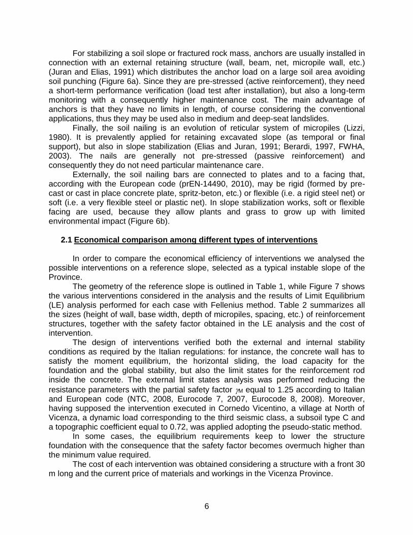
From the comparison, we note that the soil nailing and reinforcement earth wall are the cheapest solutions, followed by the wall founded on micropiles. The soil nailing costs less than half of the gabion wall price that is the highest, more than dowels.
Table 1. Reference slope and geotechnical parameters of soils.
Formation Type of soil (kN/m3) c' (kPa)
(°) Colluvium
Resistent
soil
Colluvium Clayey Silty
Sand 18 0 28
Resistent soil
Gravel 19 0,1 38
(a) (b) (c)
(d) (e) (f)
(g)
Figure 7. Interventions for the reference case: cantilever concrete retaining wall (a); gabion retaining wall (b); reinforced earth wall (c); line of drilled piles (d); tie-back
micropile wall (e); tie-back wall with micropile (f); soil nailing (g).
8
Of course, the choice of the most suitable solution has to take into account technical aspects too, such as the landslide morphology, the accessibility of the area, the time necessary for work completion and the guaranty of safety during all work phases. Table 3 summarizes the favourable conditions for application of these techniques and their main disadvantages.
Considering all the aspects, micropiles and soil nailing seems to be the most flexible solutions: they are flexible in geometry, they can be easily installed in quite all materials (heterogeneous soils, cemented soils, weak rocks, etc.) and on steep slopes with bad accessibility, since their installation is done with no big machines.
Between micropile sheet walls and soil nailing, if adopting self-drilling bars, soil nailing is a timesaver and cheaper than micropiles, especially if the micropile sheet wall needs also tendons to resist to high horizontal forces.
Reinforced earth wall is also cheap, but its construction requires a previous excavation of slope in a steeper configuration, in order to recover the space for the wall: of course, during this phase, the safety level reduces itself unless temporary supports are not adopted.
3. NEW APPROCHES IN USING SOIL NAILING
The high adaptability and the low cost of soil nailing induce to believe that this
technique has a large room for employments in slope stabilization. Several authors and country guidelines have already indicated this possible use of soil nailing, but generally, the technique is limited to the support of excavation faces or to the stabilization of very small landslides. Moreover, in Italy, just now the soil nailing is going to increase its diffusion, with a big delay compared to the other European countries.
Table 2. Characteristics, safety factor for global stability and cost of interventions.
N. Type of intervention Characteristics of intervention FS Price(1)
(Euro/m)
a Cantilever wall Height = 5,0 m; Width = 3,5 m; Depth of tooth = 0,7 m
1,29 1694
b Gabion wall Height = 5,0 m; Width = 4,5 m; base dip = 6° 1,30 2614
c Reinforced earth wall Height = 5,0 m; Width = 3,5 m 1,39 1360
d Dowels
Height = 2,0 m; Depth = 7,0 m; 1 lines of piles with 0,4 pile/m; D=60 cm;
reinforcement rods 1626
1,58 1781
e Wall founded on micropiles
Height = 2,8 m; Depth = 4,0 m; 2 micropile lines with spacing i=0,2; 0,66 micropile/m; Dex=114,3 mm; s=6,3 mm; passive anchor
R38 spacing 1,5 m; L = 10 m; = 25°
1,60 1420
f Anchored micropile sheet-wall
Height = 2,5 m; Depth = 4,2 m; 2 micropile lines with spacing i=0,5; 2 micropile/m; Dex=127 mm; s=8 mm; passive anchor R38
spacing 2,5 m; L = 12 m; = 30°
1,46 1584
g Soil Nailing L = 6, 6, 6, 9 m; ix= iz =1,6 m; = 15°; facing with steel net
1,47 1034
(1) Costs evaluated with reference to an intervention 30 m long.

9
In the following, we present some improvements adopted to this aim, such as: 1) the realization of flexible belts with soil nailing and floating anchors at support of
medium-deep landslides; 2) the development of high resistance special bars; 3) the study of behaviour and influence of floating anchors on medium/large creeping
slopes.
3.1 Flexible belts The flexible belts are 2 or more horizontal lines of bars crossing all the sliding soil
mass and the slip surface up to found in the stable deep formation. Externally the bar heads are connected one by one to plates or together to a welded wire mesh. Figure 8 shows two applications of these flexible belts installed in Vicenza Province: in these cases, each bar is fixed to a pre-cast concrete plate with a cropped conical shape.
With respect to the traditional anchorages, this solution offers some advantages: 1) The bars, like in the conventional soil nailing, are grouted along the entire length,
from the external head to their foundation. In this way the tensile stress increases along the bar profile, assuming the minimum value near the ground surface and the maximum value at the sliding surface.
2) The reinforcements are passive elements, which are not pre-stressed at installation. According to European code, passive reinforcements do not require long term
Table 3. Favorable conditions and disadvantages for slope remedial interventions.
Method Favorable condition Disadvantages
Retaining walls
• Very small and shallow landslides • Temporary stable slope during
setup
• Excavation of a large volume • Temporary supports for excavated
slope • Foundations to resist to sliding forces • Long setup if CIP concrete is adopted
Dowels • Medium deep sliding surface • Accessibility for big boring machines • Possible to couple dewatering
system
• Numerous elements to resist to sliding actions
• Expensive boring machines
Micropiles • Small and medium deep sliding surface
• Well-suited in all soils and rocks • Small and flexible boring machines
• Anchors to resist to sliding actions
Anchors • Used alone only in rock mass • No limits for length
• Supported hole in un-cemented soils • Test and long term monitoring • Protection to corrosion
Soil Nailing • Passive elements • Minimizing excavated volume • Adaptability in all soils and rock • Small and flexible boring machines • Quick setup • Low environmental impact
• Relatively high deformations of slope • Dewatering if realized under water
level • Max length 20m, with normal boring
machines

10
monitoring, so they may be covered and hidden, saving money for maintenance. 3) The installation of anchors requires the execution of a pre-drilled hole with a
supporting case. With the self-drilling nails the installation time is strongly reduced, since they don’t need pre-drilled hole and the grout is pumping down the hole as drilling progresses.
4) If in the future the slope will move consequently to a modification of its equilibrium, the bar tension will increase, but only as necessary. Altogether, the tension in the passive bars will be smaller than that of pre-stressed anchors, because the latter ones work during their entire lifecycle at the maximum stress level imposed at installation.
5) Since the tensile stresses near the ground are small, no large plates are required to guarantee the contrast to the tension in the bar, and the risk of failure for soil punching is quite nonexistent.
Compared to micropile sheet walls or cast in place walls founded on micropiles, the flexible belts have a larger application, because the length of bars may increase up to 50 m, like for tendons, and consequently they are also suitable for interventions in medium deep landslides.
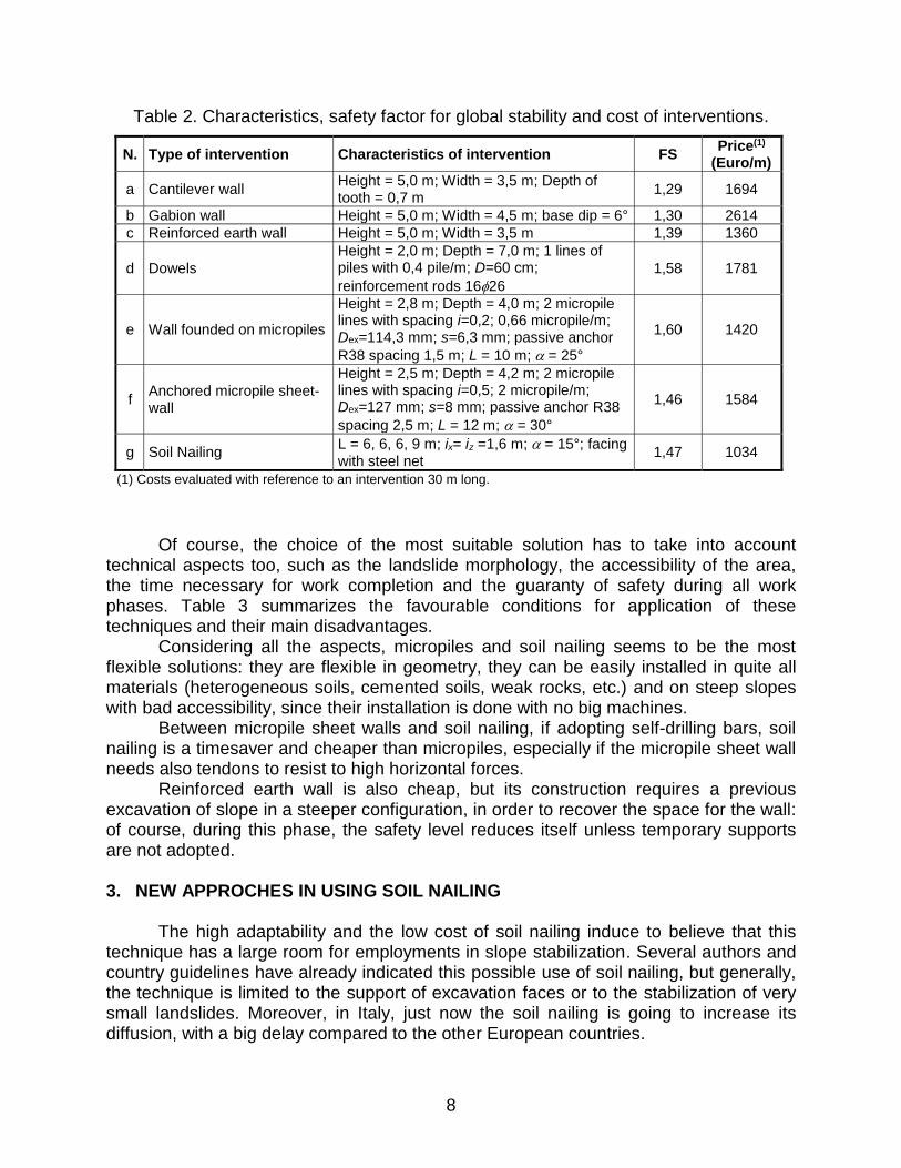
To underline the aspects previously listed, here we presents a numerical analysis performed for the intervention in Valli del Pasubio (Figure 8a). As sketched in the transversal section of Figure 9, the slope has a medium dip of 27° and the sliding surface at a maximum depth of 15 m. Table 3 summarizes the geotechnical parameters (bulk density, Mohr Coulomb resistance parameters and elastic modulus) of soil involved in the landslide.
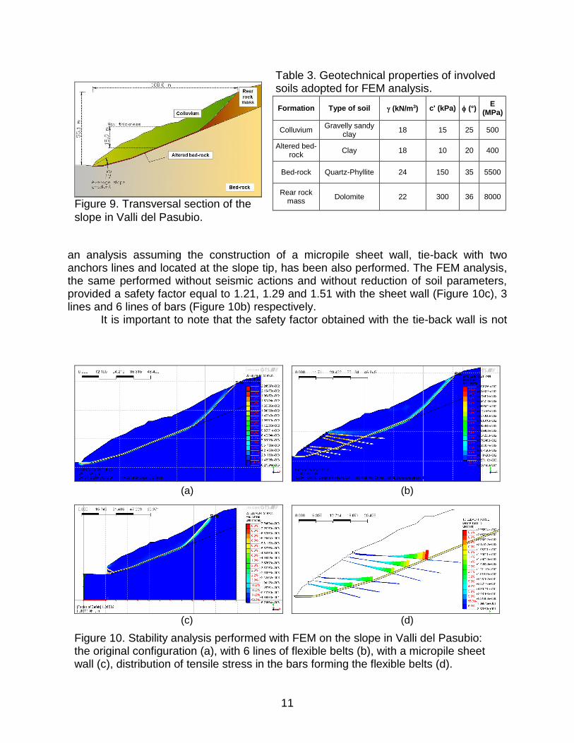
In the original configuration the safety factor, determined with a stability analysis carried out with a Finite Element Model and the Strength Reduction Method, without considering seismic forces and reduction of soil parameters, resulted approaching unit (1.03) with the maximum shear stresses concentration located along the clay layer (Figure 10a).
The remedial works complain 3 or 6 lines of self-drilling nails, 20-40 m long, each of them connected with a pre-cast concrete plate. In order to evaluate other solutions,
(a) (b)
Figure 8. Examples of flexible belts realized in two unstable slopes in Vicenza Province: (a) Valli del Pasubio; (b) Cornedo Vicentino.
11
an analysis assuming the construction of a micropile sheet wall, tie-back with two anchors lines and located at the slope tip, has been also performed. The FEM analysis, the same performed without seismic actions and without reduction of soil parameters, provided a safety factor equal to 1.21, 1.29 and 1.51 with the sheet wall (Figure 10c), 3 lines and 6 lines of bars (Figure 10b) respectively.
It is important to note that the safety factor obtained with the tie-back wall is not
Figure 9. Transversal section of the
Table 3. Geotechnical properties of involved soils adopted for FEM analysis.
Formation Type of soil (kN/m3) c' (kPa) (°) E
(MPa)
Colluvium Gravelly sandy
clay 18 15 25 500
Altered bed-rock
Clay 18 10 20 400
Bed-rock Quartz-Phyllite 24 150 35 5500
Rear rock mass
Dolomite 22 300 36 8000
slope in Valli del Pasubio.
(a) (b)
(c) (d)
Figure 10. Stability analysis performed with FEM on the slope in Valli del Pasubio: the original configuration (a), with 6 lines of flexible belts (b), with a micropile sheet wall (c), distribution of tensile stress in the bars forming the flexible belts (d).
12
sufficient according to the Italian code (NTC, 2008) and it is not possible to add another wall at the rear of the first one, because the sliding surface deepens rapidly and micropiles would become too much long. On the contrary, the soil nails could be easily extended toward the bedrock and could be installed also in the upper part of the slope, being a good modular system.
Of course, the external plate would be chosen according to aesthetic or economic criteria, the latter one assumed in the cases shown in Figure 8.
Figure 10d shows the tension stress distribution along the bars reached only if the slope collapses. Note that just at the rear of the plate the stress is very low, because the maximum tension mobilized at the sliding surface for resisting to the sliding actions is balanced by the tangent shear stresses developing at the contact soil-grout along the bar. In some cases the normal stress in the bars near the plates becoming also negative (compression stress), probably due to an anomalous flexural stress state due to the weight of plates and to possible local instability.
Another important aspect to note is the high tension reached near the sliding surface. Assuming a horizontal spacing between nails equal to 4 m, the maximum tension is 1100 kN, that may be absorbed only with a bar having a big steel section.
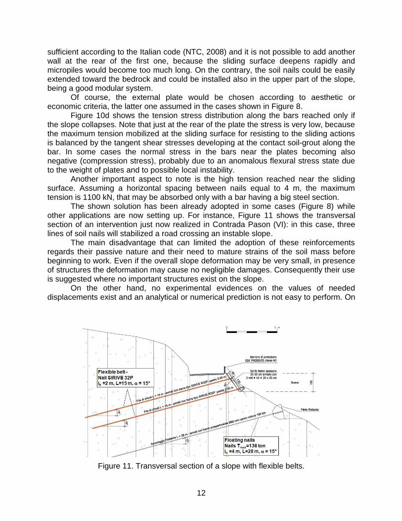
The shown solution has been already adopted in some cases (Figure 8) while other applications are now setting up. For instance, Figure 11 shows the transversal section of an intervention just now realized in Contrada Pason (VI): in this case, three lines of soil nails will stabilized a road crossing an instable slope.
The main disadvantage that can limited the adoption of these reinforcements regards their passive nature and their need to mature strains of the soil mass before beginning to work. Even if the overall slope deformation may be very small, in presence of structures the deformation may cause no negligible damages. Consequently their use is suggested where no important structures exist on the slope.
On the other hand, no experimental evidences on the values of needed displacements exist and an analytical or numerical prediction is not easy to perform. On
Figure 11. Transversal section of a slope with flexible belts.

13
this aspect, we need to develop more experience by monitoring the time-behaviour of reinforcements installed in-situ or within small scale physical models.
3.2 High resistance special bars
The Dalla Gassa Company is studying the coupling of self-drilling bars for soil
nailing with strands for conventional tendon, obtained thank to the injection of a high resistance and low shrinkage glue in the gap among the strands and the bar internal surface. In order to obtain final tensile strength within the 50 - 400 ton range, the coupling is designed for bars with different diameters: for instance, Figure 12 shows the coupling of a 60mm diameter bar with 3 tendons with 7 strands and of a 32mm diameter bar with one tendon.
These special bars provide the following advantages: 1) They permit to reach the same
tension resistance with small steel sections, as showed in Figure 13 that compares the tensile force - axial strain relationship for a 38 mm normal bar with that of a 32 mm special bar (with 7 strands inside).
2) While the normal bars present a brittle rupture due to the hardening of high-strength steel during the rolling process, the special bars guarantee a large reserve of resistance after yielding, thus to better resist to cyclic solicitations during seismic events.
3) Even if the deformability of the special bar is higher, it is possible to increase the stiffness of the bar as needed applying a pre-stress to the strands during the coupling procedure. The fact is evident in Figure 13, which reports some results of preliminary tests performed on a 32L bar coupled with pre-stressed strands: the stiffness gain can increase more than 10%.
4) The setup of the special bar is the
Figure 12. Sections of special bars for nailing having different tension resistance.

14
same adopted for the normal bar, without increase of installation cost if the pre-stress is not applied. Some more costs exist if the strands are pre-stressed before hardening of the glue.
3.3 Future studies on the effect of soil nailing on creeping slope
The creeping slopes are movements characterized by slow and very slow
displacement rates. In normal conditions, their slope safety factor is greater than unit and the displacement rate is very low, but consequently to heavy and/or long rainy events the internal stress equilibrium may change inducing a temporary acceleration of movements with a safety factor approaching the unit. In soils the creeping strain rate exhibits an exponential dependence from the ratio between the shear stress mobilized and the maximum possible shear stress, the latter depending from the soil frictional resistance. If this ratio is small in comparison with the unit (0.4-0.7) the creeping rate approaches zero but, if the ratio increases to value in the range 0.8-0.9, even if the soil does not reach the failure condition, the creeping rate exhibits an increase of one or more orders of magnitude.
In our region and, more generally, in Italy, the list of creeping slopes is very long: for instance, we may remember Fantoni and Rotolon landslides in Vicenza Province, Alverà and Mortisa landslides in Belluno Province, etc.
For completely stopping these kinds of movement, generally, very expensive remedial works are needed, especially if the landslide is large or presents a deep sliding surface.
Moreover, rigid structures, like concrete walls, do not seem to be suitable for this purpose. The flexible belts seem to be a possible alternative to other mitigation works.
0.0 0.5 1.0 1.5 2.0 2.5 3.0 3.5 4.0 4.5
Bar elongation (%)
0
200
400
600
TE
NS
ILE
FO
RC
E (
kN
)
SIRIVE R32L + UNLOADED STRANDS
SIRIVE R38
SIRIVE R32L + PRELOADED STRANDS
Figure 13. Tensile force vs. axial strain for a normal 38mm and a special 32mm bars.

15
In fact, even if the slope moves, the soil may flow around the reinforcements and their terminal plates without damaging completely these elements (Figure 14). At the same time, the frictional stresses mobilized along the bars and the bearing capacity of terminal plates, all taken in care from the nails, induces an overall reduction of the sliding forces, a reduction of the mean mobilized shear stress along the sliding surface and, consequently, a decrease of the creeping displacement rate.
We labeled these kinds of solutions “floating reinforcements” since, during the creeping displacements, the soil mass could cover the reinforcements or they could fit their positions inside the sliding mass without losing their capability to reduce the sliding forces.
In order to evaluate the adaptability and the capability of flexible belts for the control and the reduction of displacement rate of these phenomena, we are planning a set of tests in a 1g physical model. Two caissons (Figure 15), which can independently change their inclination, constitute the model.
CREEPING SLOPE
mob
CREEPING SLOPE
reduced mob
Configuration after slope
moving for creep
Deformed floating
reinforcements
ANCORAGGIO FLOTTANTE SIRIVE®
PATENT VI2010A000020
Figure 14. Scheme of a creeping slope and resistant mechanism of flexible belts.
Figure 15. 1g physical model for testing the effects of floating reinforcements on creeping slopes.

16
Within it, we are going to reproduce a small slope with or without reinforcements: we will induce the slope collapse increasing the angle of the sliding surfaces. Since the rigid bases of caissons and each reinforcement are all connected with load cells, we plan to quantify the partial contributes of each elements to the stability of slope.
The research in the physical model aims to evaluate various reinforcement setups, differing in bar spacing, terminal plate geometry, slope geometry and soil type.
At the same time, we are planning an in-situ monitoring activity on some reinforcements installed in different slopes: the aim of this parallel activity is the evaluation of the load taken in care by floating reinforcements in time and during different weather conditions.
The monitoring, carried out for a long period, will supply suitable data to evaluate the relation among weather conditions, temporary displacement rate and loads supported by the reinforcements, with particular care to the creep movements. 4. FINAL REMARKS
Among the various methods for slope stabilization, the tied-back micropile sheet-
walls and soil nailing are the most used in our region, because they are economical and well-suited in quite all the landslide types.
Moreover, between these two techniques, the soil nailing seems to present a larger number of advantages, and, even if the soil nailing is a technique 30-years old, it has also substantial room for improvement, especially in applications vote to slope stabilization.
In this work, we illustrated some cases in which the soil nails, installed in a configuration that we call “flexible belts” and “floating reinforcements”, were used for the stabilization of medium-high deep landslides. These techniques seem to give good results and many installations have already carried out in Vicenza Province.
For the future, we would like to study the capability of floating reinforcements for the mitigation of creeping displacement rates of slow and very slow instable slopes.
5. REFERENCES
Berardi, R. (1997). Chiodatura dei terreni e reticoli di pali. IV Conv. Naz. Ricercatori Universitari CNR, Perugia, vol. II, 289-321 pp. In Italian language.
Bruce, D.A. (1988). Developments in Geotechnical Construction Process for Urban Engineering, Civil Engineering Practice, Vol.3, No.1, 49-97 p.
Eurocodice 7 (1997): Geotechnical design, UNI EN 1997 Part-1, -2, -3.
Eurocodice 8 (1998): Seismic design of structures, UNI EN 1998 Part-1, -5.
Favero & Milan Ingegneria, Sogen, Studio Cancelli Associato, ENSER (2010). Stabilizzazione e ricomposizione della frana in localita' Fantoni, Comune Di Recoaro Terme (VI). Design of the Soil Protection Division of Vicenza Province. In Italian language.
Ferraro V. (2011). Intervento di ripristino di un tratto di strada di collegamento in localita' Zao, nel comune di Valli del Pasubio (VI). Design of the Soil Protection Division of Vicenza Province. In Italian language.
FHWA-IF-03-017, 2003. Geotechnical Engineering circular No. 7 – Soil Nail Walls.

17
Floris, M., D’Alpaos, A., De Agostini, A., Tessari, G., Stevan, G. and Genevois, R. (2011). An analysis of the November 2010 exceptional rainfall event in NE Italy. Proceedings of the Second World Landslide Forum – 3-7 October 2011, Rome, in printing.
Juran, I., Elias, V. (1991). Ground anchors and soil nails in retaining. Foun. Eng. Manual, part. 26, H.Fang (ed.) Van Nostran Reinhold.
Lizzi, F. (1980). The use of root pattern piles in the underpinning of monuments and old buildings and in the consolidation of historic centres, L’Industria delle Costruzioni, No. 110, 25 pp.
NTC (2008). Nuove Norme Tecniche per le Costruzioni, D.M. 14.01.2008, G.U. n°29 del 04.02.08, Sup. n° 30.
prEN 14490 (2010). Execution of special geotechnical works – soil nail.
Stevan, G. (2011). Sistemazione dei dissesti idrogeologici in località Xometto nel Comune di Posina. Design of the Soil Protection Division of Vicenza Province. In Italian language.