reinforced concrete by ultimate strength design
TRANSCRIPT

Unless otherwise noted, the content of this course material is licensed under a Creative Commons Attribution 3.0 License. http://creativecommons.org/licenses/by/3.0/
© 2009, Peter Von Buelow
You assume all responsibility for use and potential liability associated with any use of the material. Material contains copyrighted content, used in accordance with U.S. law. Copyright holders of content included in this material should contact [email protected] with any questions, corrections, or clarifications regarding the use of content. The Regents of the University of Michigan do not license the use of third party content posted to this site unless such a license is specifically granted in connection with particular content. Users of content are responsible for their compliance with applicable law. Mention of specific products in this material solely represents the opinion of the speaker and does not represent an endorsement by the University of Michigan. For more information about how to cite these materials visit https://open.umich.edu/education/about/terms-of-use.
Any medical information in this material is intended to inform and educate and is not a tool for self-diagnosis or a replacement for medical evaluation, advice, diagnosis or treatment by a healthcare professional. You should speak to your physician or make an appointment to be seen if you have questions or concerns about this information or your medical condition. Viewer discretion is advised: Material may contain medical images that may be disturbing to some viewers.
University of Michigan, TCAUP Structures II Slide 2/26
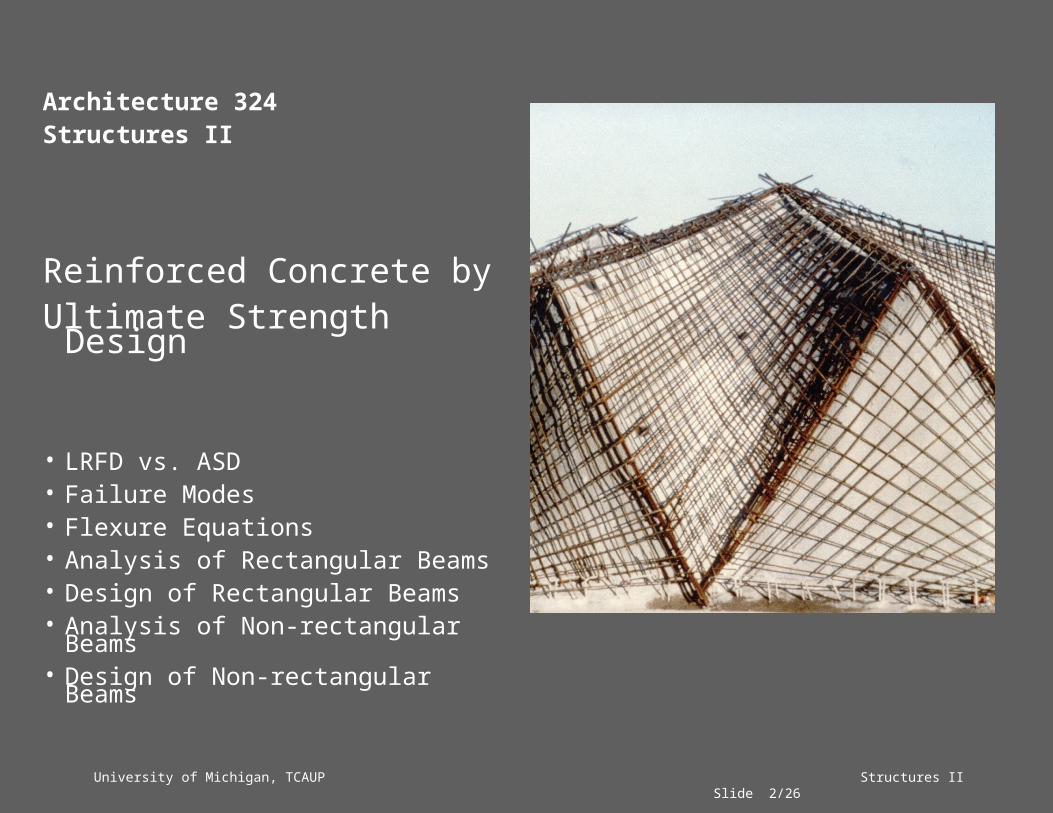
Architecture 324Structures II
Reinforced Concrete byUltimate Strength Design
• LRFD vs. ASD• Failure Modes• Flexure Equations• Analysis of Rectangular Beams• Design of Rectangular Beams• Analysis of Non-rectangular Beams• Design of Non-rectangular Beams

University of Michigan, TCAUP Structures II Slide 3/26
Allowable Stress – WSD (ASD)
• Actual loads used to determine stress• Allowable stress reduced by factor of safety
Ultimate Strength – (LRFD)
• Loads increased depending on type load
Factors: DL=1.4 LL=1.7 WL=1.3U=1.4DL+1.7LL
• Strength reduced depending on type force
Factors: flexure=0.9 shear=0.85 column=0.7
failureactual FSFf .).(
nu MM
Examples:WSD
Ultimate Strength
'1.0 cv ff
'45.0 cb ff
nu MM 9.0
nu VV 85.0
nu PP 70.0
University of Michigan, TCAUP Structures II Slide 4/26
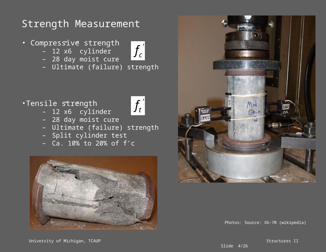
Strength Measurement
• Compressive strength– 12”x6” cylinder– 28 day moist cure– Ultimate (failure) strength
•Tensile strength– 12”x6” cylinder– 28 day moist cure– Ultimate (failure) strength– Split cylinder test– Ca. 10% to 20% of f’c
'cf
'tf
Photos: Source: Xb-70 (wikipedia)

University of Michigan, TCAUP Structures II Slide 5/26
Failure Modes
• No Reinforcing– Brittle failure
• Reinforcing < balance– Steel yields before concrete fails– ductile failure
• Reinforcing = balance– Concrete fails just as steel yields
• Reinforcing > balance– Concrete fails before steel yields– Sudden failure
bdAs
yf200
min
yy
cbal ff
f870008700085.0 '
1
bal 75.0max
!h!SuddenDeatmax
Source: Polyparadigm (wikipedia)

University of Michigan, TCAUP Structures II Slide 6/26
1
1 is a factor to account for the non-linear shape of the compression stress block.
f'c 10 0.85
1000 0.852000 0.853000 0.854000 0.855000 0.86000 0.757000 0.78000 0.659000 0.65
10000 0.65
ca 1
Image Sources: University of Michigan, Department of Architecture
University of Michigan, TCAUP Structures II Slide 7/26
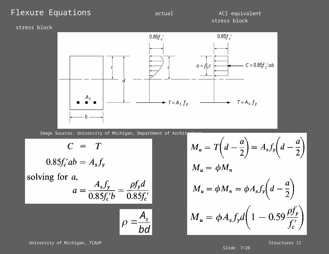
Flexure Equations actual ACI equivalent stress block stress block
bdAs
Image Sources: University of Michigan, Department of Architecture

University of Michigan, TCAUP Structures II Slide 8/26
Balance Condition
From similar triangles at balance condition:
Use equation for a. Substitute into c=a/1
Equate expressions for c:
Image Sources: University of Michigan, Department of Architecture
University of Michigan, TCAUP Structures II Slide 9/26
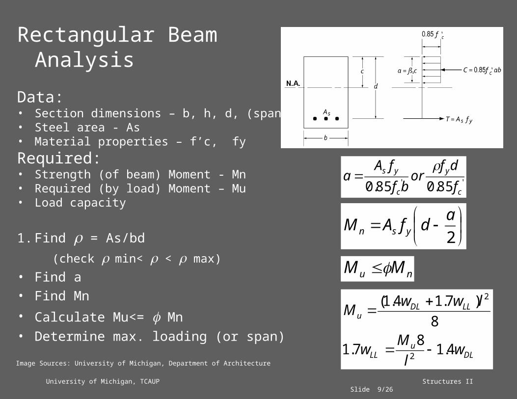
Rectangular Beam Analysis
Data:• Section dimensions – b, h, d, (span)• Steel area - As• Material properties – f’c, fyRequired:• Strength (of beam) Moment - Mn• Required (by load) Moment – Mu • Load capacity
1. Find = As/bd(check min< < max)
• Find a• Find Mn• Calculate Mu<= Mn• Determine max. loading (or span)
'' 85.085.0 c
y
c
ys
fdf
orbf
fAa
2adfAM ysn
DLu
LL
LLDLu
wlMw
lwwM
4.187.1
8)7.14.1(
2
2
nu MM
Image Sources: University of Michigan, Department of Architecture

University of Michigan, TCAUP Structures II Slide 10/26
Rectangular Beam Analysis
Data:• dimensions – b, h, d, (span)• Steel area - As• Material properties – f’c, fyRequired:• Required Moment – Mu
1. Find = As/bd(check min< < max)
University of Michigan, TCAUP Structures II Slide 11/26
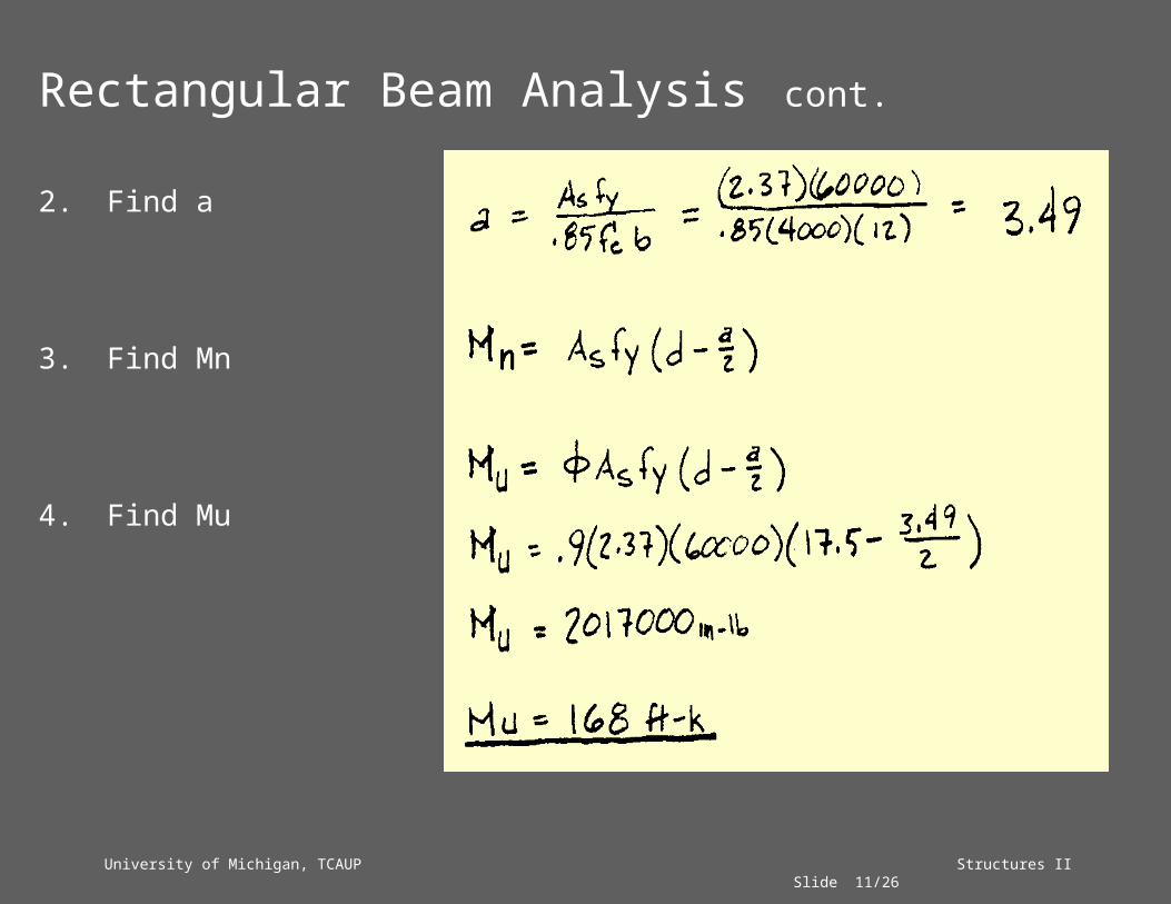
Rectangular Beam Analysis cont.
2. Find a
3. Find Mn
4. Find Mu

University of Michigan, TCAUP Structures II Slide 12/26
Slab Analysis
Data:• Section dimensions – h, span
take b = 12”• Steel area - As• Material properties – f’c, fyRequired:• Required Moment – Mu• Maximum LL in PSF

University of Michigan, TCAUP Structures II Slide 13/26
Slab Analysis
1. Find a
2. Find force T
3. Find moment arm z
4. Find strength moment Mn
University of Michigan, TCAUP Structures II Slide 14/26
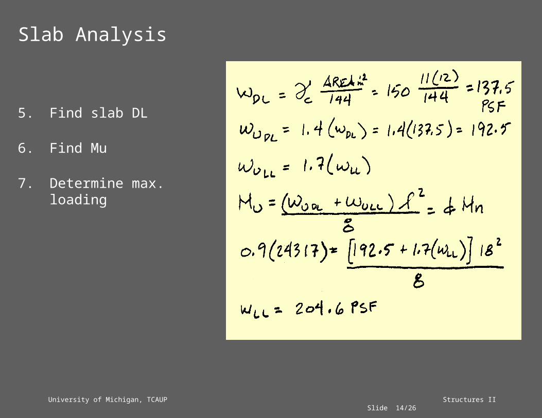
Slab Analysis
5. Find slab DL
6. Find Mu
7. Determine max. loading
University of Michigan, TCAUP Structures II Slide 15/26
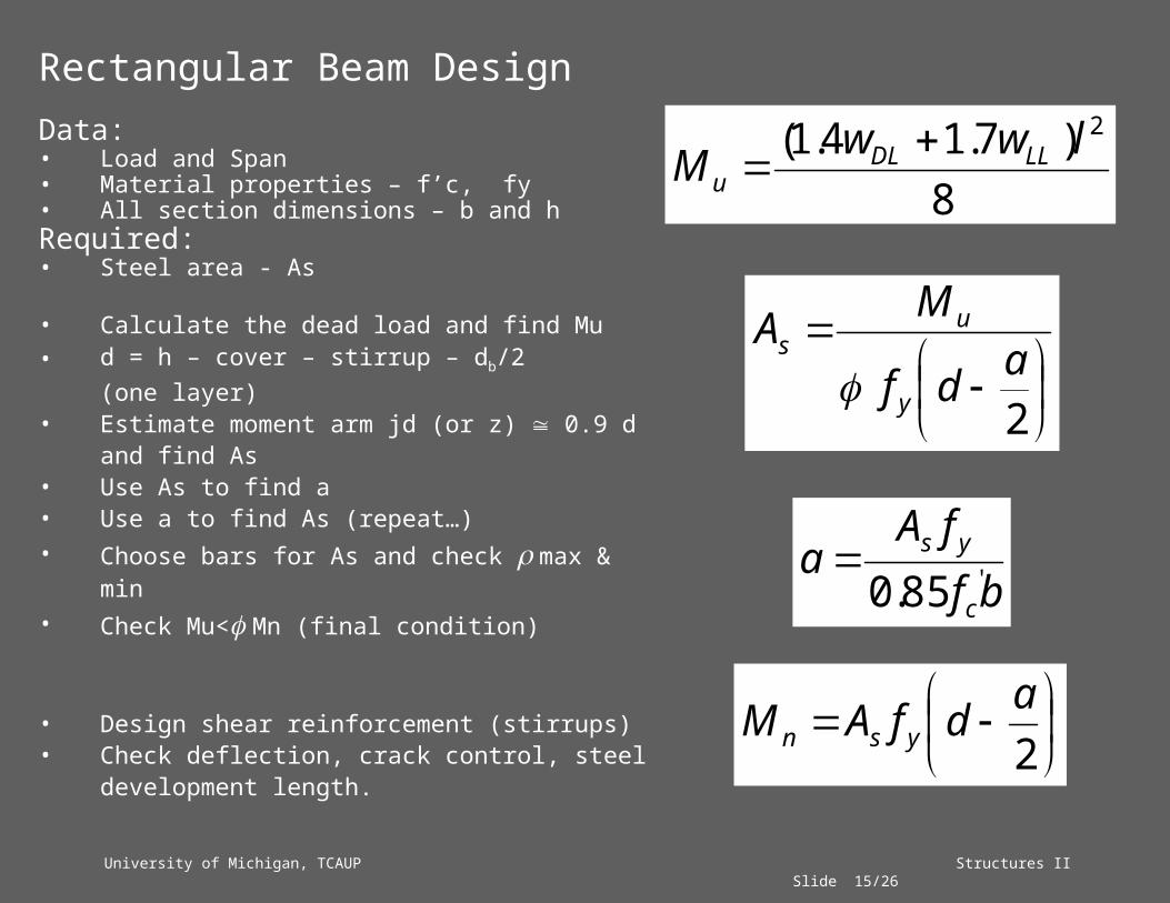
Rectangular Beam DesignData:• Load and Span• Material properties – f’c, fy• All section dimensions – b and hRequired:• Steel area - As
• Calculate the dead load and find Mu• d = h – cover – stirrup – db/2 (one layer)• Estimate moment arm jd (or z) 0.9 d
and find As• Use As to find a• Use a to find As (repeat…)• Choose bars for As and check max & min• Check Mu< Mn (final condition)
• Design shear reinforcement (stirrups)• Check deflection, crack control, steel
development length.
8)7.14.1( 2lwwM LLDL
u
bffA
ac
ys'85.0
2adf
MAy
us
2adfAM ysn

University of Michigan, TCAUP Structures II Slide 16/26
Rectangular Slab Design
Data:• Load and Span• Material properties – f’c, fyRequired:• All section dimensions – h• Steel area - As
1. Calculate the dead load and find Mu
2. Estimate moment arm jd (or z) 0.9 d and find As
3. Use As to find a4. Use a to find As (repeat…)
University of Michigan, TCAUP Structures II Slide 17/26
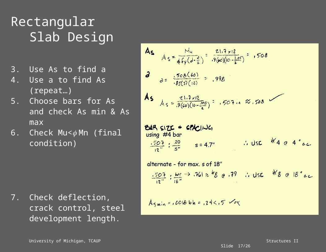
Rectangular Slab Design
3. Use As to find a4. Use a to find As (repeat…)5. Choose bars for As and
check As min & As max 6. Check Mu< Mn (final
condition)
7. Check deflection, crack control, steel development length.

University of Michigan, TCAUP Structures II Slide 18/26
Quiz 9
Can f = Mc/I be used in Ult. Strength concrete beam calculations? (yes or no)
HINT:
WSD stress Ult. Strength stress
Source: University of Michigan, Department of Architecture Source: University of Michigan, Department of Architecture
University of Michigan, TCAUP Structures II Slide 19/26
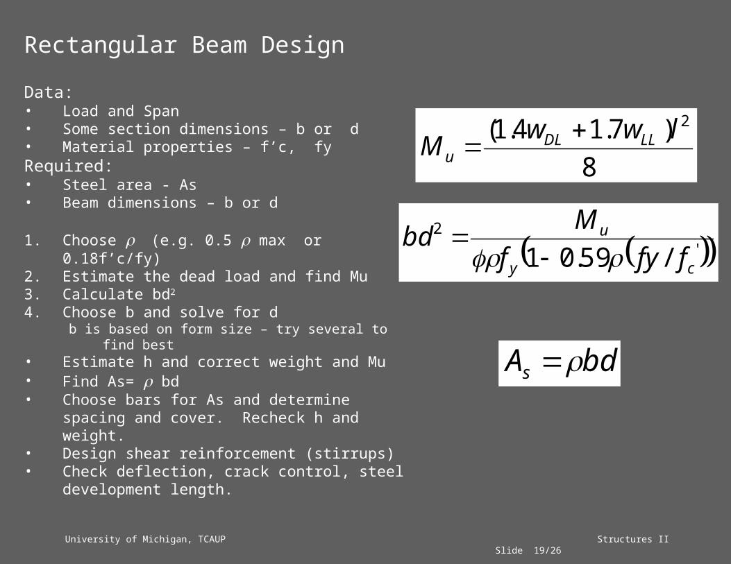
Rectangular Beam Design
Data:• Load and Span• Some section dimensions – b or d• Material properties – f’c, fyRequired:• Steel area - As• Beam dimensions – b or d
1. Choose (e.g. 0.5 max or 0.18f’c/fy)2. Estimate the dead load and find Mu3. Calculate bd2
4. Choose b and solve for db is based on form size – try several to find best
• Estimate h and correct weight and Mu• Find As= bd• Choose bars for As and determine spacing
and cover. Recheck h and weight.• Design shear reinforcement (stirrups)• Check deflection, crack control, steel
development length.
8)7.14.1( 2lwwM LLDL
u
'2
/59.01 cy
u
ffyfMbd
bdAs

University of Michigan, TCAUP Structures II Slide 20/26
Rectangular Beam Design
Data:• Load and Span• Material properties – f’c, fyRequired:• Steel area - As• Beam dimensions – b and d
1. Estimate the dead load and find Mu2. Choose (e.g. 0.5 max or 0.18f’c/fy)

University of Michigan, TCAUP Structures II Slide 21/26
Rectangular Beam Design cont
3. Calculate bd2
4. Choose b and solve for db is based on form size.
try several to find best
University of Michigan, TCAUP Structures II Slide 22/26
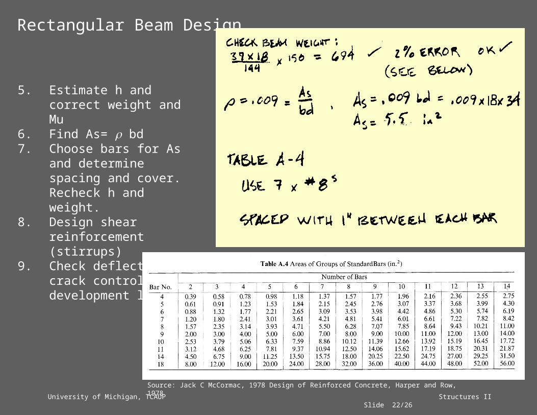
5. Estimate h and correct weight and Mu
6. Find As= bd7. Choose bars for As and
determine spacing and cover. Recheck h and weight.
8. Design shear reinforcement (stirrups)
9. Check deflection, crack control, steel development length.
Rectangular Beam Design
Source: Jack C McCormac, 1978 Design of Reinforced Concrete, Harper and Row, 1978
University of Michigan, TCAUP Structures II Slide 23/26
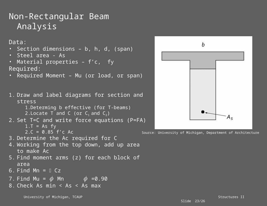
Non-Rectangular Beam Analysis
Data:• Section dimensions – b, h, d, (span)• Steel area - As• Material properties – f’c, fyRequired:• Required Moment – Mu (or load, or span)
1. Draw and label diagrams for section and stress1. Determing b effective (for T-beams)2. Locate T and C (or C1 and C2)
2. Set T=C and write force equations (P=FA)1. T = As fy2. C = 0.85 f’c Ac
3. Determine the Ac required for C4. Working from the top down, add up area to
make Ac5. Find moment arms (z) for each block of area6. Find Mn = Cz7. Find Mu = Mn =0.908. Check As min < As < As max
Source: University of Michigan, Department of Architecture

University of Michigan, TCAUP Structures II Slide 24/26
Analysis Example
Given: f’c = 3000 psify = 60 ksiAs = 6 in2
Req’d: Capacity, Mu
1. Find T
2. Find C in terms of Ac
3. Set T=C and solve for Ac
Source: University of Michigan, Department of Architecture
University of Michigan, TCAUP Structures II Slide 25/26
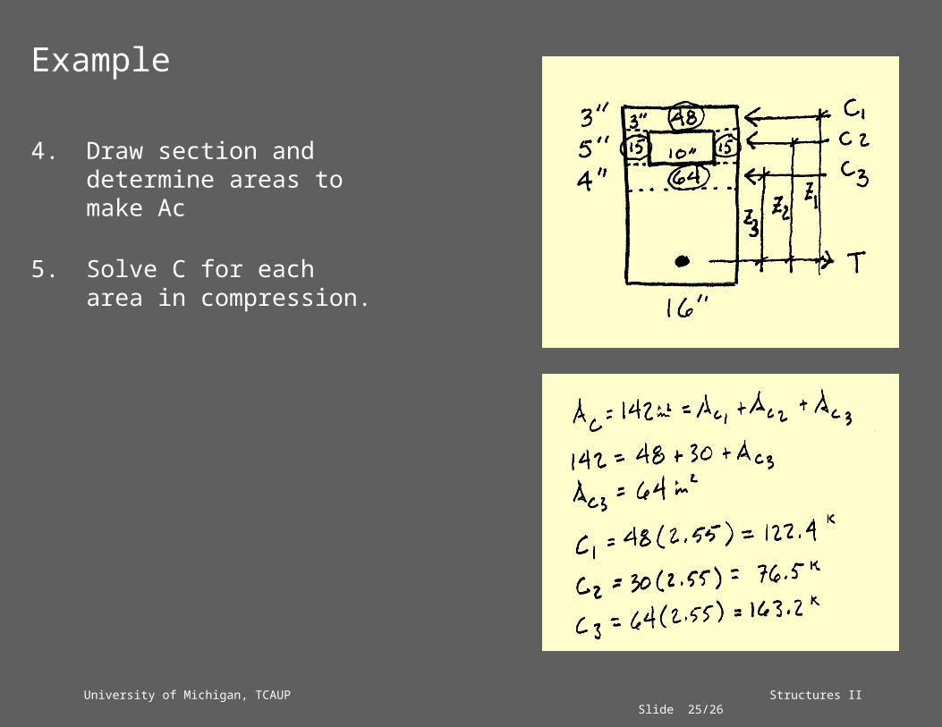
Example
4. Draw section and determine areas to make Ac
5. Solve C for each area in compression.

University of Michigan, TCAUP Structures II Slide 26/26
Example
6. Determine moment arms to areas, z.
7. Calculate Mn by summing the Cz moments.
8. Find Mu = Mn

University of Michigan, TCAUP Structures II Slide 27/26
Other Useful Tables:
Image Sources: Jack C McCormac, 1978 Design of Reinforced Concrete, Harper and Row, 1978