rehau tech manual
DESCRIPTION
tech manual.pdfTRANSCRIPT

RAUPEXRadiant Floor Heating Systems
Technical Manual
™

RFH Technical Manual 9.96 1 - 1
Please also refer to "RAUPEX Radiant FloorHeating Systems Catalog/Price List" whichprovides a detailed description of each systemcomponent and includes information on weight,packaging and price.
REHAU also offers hydronic heating systemsfor special applications such as snow melting,material storage heating, stair de-icing andmany others.
REHAU has over 20 years of experience in thefield of hydronic heating, and has producedover 500 million feet (150 million meters) ofcross-linked polyethylene tubing for heatingsystems.
Over 200,000 building projects, with a totalarea exceeding 250 million square feet (23million square meters) are in successful opera-tion.
1.IntroductionThis technical manual provides a thoroughunderstanding of the design and installation ofradiant floor heating systems using cross-linkedpolyethylene tubing produced byREHAU. It is intended to help experiencedhydronic heating professionals achieve the bestresults with REHAU's RAUPEX heating sys-tems.
Fig. 1.2:Floor of aircraft hangar incorporating RFH system.
1.1 DescriptionRAUPEX is REHAU's tradename for a speciallyformulated cross-linked polyethylene (PEX).RAUPEX is an unusually strong and stablepolymer that stands up well to strenuous usewhich makes it ideally suited for hydronic heat-ing systems.
RAUPEX heating tube, either with oxygendiffusion barrier (RAUPEX B) or without barrier(RAUPEX), is fully embedded in floor thermalmass or placed under wood subflooring. Whenused in conjunction with manually or thermo-statically controlled supply- and return-flowvalves that distribute water through the tubeand back to a boiler, the system transforms theentire floor into a warm-water, low temperatureheater.
Fig. 1.3:High ceiling areas are ideal for radiant floorheating.
Fig. 1.1:REHAU radiant floor heating in an industrial project.

1 - 2 9.96 RFH Technical Manual
�������������������������
���������90
80
70
60
50
4050 60 70 80 9040Mean radiant temperature (°F)
Air
te
mp
era
ture
(°F
)
Cold
Hot
����
Approximate Comfort Zone
Convection heating
Radiantheating
1.2 ApplicationThe REHAU radiant floor heating system canheat a whole room or it may serve in combina-tion with other auxiliary heating systems. Thisoffers you great flexibility in selecting heatoutput. For example, 60% of an area’s heatmight be supplied by the floor heating system,with the remaining 40% coming from a second-ary system such as radiators or fan coil units.
Our system can be used in a wide variety ofbuilding types and uses including residences,schools, auditoriums, churches, convalescenthomes, supermarkets, hospitals, warehouses,and factories. While well-insulated buildingsoffer ideal environments for floor heating,weather-exposed projects - parking garageentrance ramps, outdoor stairways, stadiums,parking decks, aircraft runways, and bridges -which must be kept free from ice and snow arealso intelligent locations for floor heating sys-tems.
1.3 Room temperatureMost people relate their comfort to ambientroom temperature. However, many factorsbeside thermal temperature influence thermalcomfort, making it impossible to specify “idealroom temperature”. Instead, target tempera-tures must always be related to specific ambi-ent conditions, including such things as theclothes we wear for particular activities. Calcu-lated heat requirements for room temperaturesmust, therefore, always be regarded as meantemperatures and must allow for ambientinfluences.
1.4 Mean radiant temperatureThe mean radiant temperature (MRT) of a roomis most simply defined as the average tempera-ture of its surfaces. Fig. 1.5 illustrates thecombined effect of ambient room temperatureand MRT on human comfort. The effect ofMRT on the occupants in a room depends onthe size and temperature of the room surfacesand the occupant’s distance from these sur-faces. RFH directly affects mean radiant tem-perature by heating the room’s surfaces. Thefloor is directly heated to the design floor sur-face temperature, and the walls and ceiling areheated by radiant energy (heat) from the floor.Therefore, occupants benefit not only from theincrease in ambient room temperature createdby RFH systems but also from the increase inthe MRT.
1.5 Temperature distributionUniform temperature distribution through theroom is an important factor in human comfort.A room temperature profile, determined bymeasuring room temperatures along specifiedvertical and horizontal planes in the room, givesa clear picture of the uniformity of temperaturedistribution throughout the room, and can helpyou identify areas of significant heat loss.
CeilingHeight
EyeLevel
61˚ 68˚ 75˚ 61˚ 68˚ 75˚ 61˚ 68˚ 75˚ F
16˚ 20˚ 24˚ 16˚ 20˚ 24˚ 16˚ 20˚ 24˚ C
OptimumHeating
RadiantFloor
Heating
ForcedAir
Heating
Fig. 1.4:This figure compares temperature profiles for RFH, forced air and optimum heating distribution.You'll note that radiant floor heating’s temperature profile very closely approximates an ideal tem-perature distribution.
1.7 Heat sourcesThere are few restrictions, in principle, to theheat source you choose to use in conjunctionwith a REHAU radiant floor heating system.Two conditions, however, must be kept in mindfor any heat source:
• First, the heat source must be sufficient tosupply the heat required, including auxiliaryrequirements such as domestic hot water.Typical heat sources are low and high tem-perature boilers, designated hot watertanks, heat pumps, solar and, in certainregions, geothermal.
• Second, the maximum flow temperature inthe floor heating circuit must be regulatedby modern control systems to assure opti-mum comfort, to avoid damage to the tubeor floor, and to prevent excessive floortemperatures.
The shape of these room temperature profilesdepends on the type of heating system in use;the position, size and temperature of the areadissipating heat; the outside temperature; thearrangement of windows; and the position ofthe temperature sensor.
1.6 Floor temperatureA cold floor can literally draw the warmth en-ergy from your body using your feet as thetransfer point. As a result, floors are an excel-lent heating source. Floor temperature limita-tions do exist to protect certain types of floorfinishes while still providing enough heat tomeet the room requirement.
Fig. 1.5:This figure compares air temperature and meanradiant temperature showing that the comfortzone depends on the average temperature ofthe surface within the room as well as the airtemperature. RFH raises the temperature of thesurfaces in the room allowing inhabitants to becomfortable at lower air temperatures.(Adapted from I=B=R Guide #400)

RFH Technical Manual 9.96 1 - 3
1.8 Tube circuit laying patterns
1.8.1 SerpentineA serpentine pattern allows for warmer floorsalong the perimeter areas of a room or zone,where it is needed. Floor surface temperaturesalong perimeter walls will be greater than floorsurface temperatures in the interior of theroom, where occupants are more likely togather. For residences, floor surface tempera-tures can be as high as 95°F (35°C) along theperimeter.
Fig. 1.6:Serpentine pipe-layout pattern.
Fig. 1.7:Surface temperature profile for serpentine pipe-layout pattern.��QQ����������
��QQ��
�Q�
����������������QQQQQQQQQQQQQQQQ����������������
�������QQQQQQQ�������
������������������������������������������������
QQQQQQQQQQQQQQQQQQQQQQQQQQQQQQQQQQQQQQQQQQQQQQQQ
������������������������������������������������

1 - 4 9.96 RFH Technical Manual
Fig. 1.8:Counterflow spiral pipe-layout pattern.
Fig. 1.9:Surface temperature profile for counterflow spiral pipe-layout pattern.
1.8.2 Counterflow spiralThis method allows closer tube spacing thanthe serpentine patterns, since there are fewerbend radius constraints. In addition, surfacetemperatures are distributed more evenly bylaying tube in counterflow spiral form. ���
���QQQQQQ������
����
QQQQ
����
������������������������
QQQQQQQQQQQQQQQQQQQQQQQQ
������������������������
��QQ����������
��QQ��

RFH Technical Manual 9.96 1 - 5
Fig. 1.10:Perimeter and occupied areas using one circuit.
Fig. 1.11:Perimeter and occupied areas requiring two circuits.
1.8.3 CombinationOften the most effective way to heat a room isto use a serpentine pattern at the edges and acounterflow spiral pattern in the middle. Thereare many ways these basic patterns can bevaried to meet the unique requirements of anyapplication. Figures 1.10 and 1.11 show varia-tions which allow for greater heat along perim-eter areas in a zone.
1.8.4 Tube spacing and depthREHAU radiant floor heating circuits may belaid in a variety of patterns. The tube spacingand depth in the thermal mass affect the unifor-mity of the floor surface temperature. There is adirect correlation between tube spacing andsupply water temperature. The closer the tubespacing the lower the supply water temperaturewhich corresponds to a design with greaterefficiency.
In principle, the heat requirement of a roommay be covered regardless of the laying pat-tern. However, the heating system must notonly fulfill the task of covering the heat require-ment but also create a sense of comfort. Keepin mind that the heat requirement of a room ishigher near exterior wall (perimeter areas) anddiminishes toward the center of the room(occupied area). The higher heat requirement atexterior walls and windows can usually be metby decreasing the tube spacing in comparisonto the occupied area.
Occupied area
Outside wall
Perimeter area
Outside wall
Return
Supply
Occupied area
Outside wall
Perimeter area
Outside wall
Return
Return
SupplyCircuit 1
Circuit 2Supply

1 - 6 9.96 RFH Technical Manual
Weather-compensating controls can be veryeffective at matching heating system output toexisting heat load throughout the heating sea-son. Because of these fine tuning adjustments,room temperature can remain very stable withvery little fluctuation. The disadvantages asso-ciated with these controls are the comparativelyhigher component costs and somewhat higherlevel of skill required for planning and installa-tion.
Thermostatic controlAnother method to control radiant floor heatingsystems is with thermostatic devices. Thesecontrols sense floor supply water temperatureand mix boiler primary loop water with floorreturn water to maintain a preset temperature.Because thermostatic controls are set to main-tain a specific supply water temperature theymay require manual adjustment during theheating season. Overshooting the thermostatset point may be more noticeable with thermo-static control than with weather-compensatingcontrol. However, thermostatic control is typi-cally much less expensive than weather-com-pensating control and is easier for installers tounderstand. Many homes have been heatedsuccessfully with this type of control.
Room controlIn many buildings, it may be necessary tocontrol individual rooms separately from otherrooms without adjusting the thermostatic orweather-compensating control. One way toaccomplish this is with valve actuators attachedto individual manifold loops that service therooms where control is desired. These lowvoltage actuators close individual manifoldloops when the associated room thermostat issatisfied. Installers must plan for room thermo-stat wiring to the manifold locations duringsystem rough-in.
Fig. 1.12:Constant temperature heat source with radiant floor heating circuit. Flow temperature is regulated inrelation to outside temperature.
1.9 Control systemsThe amount of energy consumed by a heatingsystem is largely determined by the way inwhich it is operated. Avoidable energy lossresulting from poor system control design,improper heat source operation or failure toprovide system service may account for up to20% of the annual consumption of heatingenergy. Proper design of a floor heating controlsystem can help to enhance system perfor-mance, efficiency and comfort.
Properly designed radiant floor heating systemsrequire a much lower supply water temperaturethan conventional hydronic heating systems.Effective design of a floor heating system re-quires careful attention to control of the sys-tem. REHAU offers a variety of components forcontrolling radiant floor systems using RAUPEXtubing. Please refer to our "RAUPEX RadiantFloor Heating Systems Design Supplement" fordetailed diagrams of suggested controlschemes. Generally, these systems have thetask of adjusting the supply water temperatureaccording to the many variables that affect flooroutput, and ultimately human comfort. Thesecontrols should act in such a way that:
- rooms are not overheated.- rooms are heated when and as required.- compensates for free energy, such assunshine.
- heat input is switched on or off at theproper time.
Heat output of radiant floor systems can beregulated by adjusting water flow rate or byadjusting supply water temperature. Adjustingsupply water temperature has a much morelinear effect on heat output. Therefore, mostcontrol systems vary the supply water tempera-ture to control radiant floor heating systems.REHAU offers both weather-compensating andthermostatic methods to accomplish this con-trol.
Weather-compensating controlWeather-compensating controls generallycompare electrical resistance inputs from anoutdoor temperature sensor and a supply watertemperature sensor. With these inputs, avoltage output signal is generated based on anadjustable “heating curve” (ratio). The resultingoutput signal is used to control a heat source ora motorized mixing valve. Some controls haveadditional output signals for controlling systemcirculators or zone valves and may be used tocontrol both low temperature and high tem-perature demands.
A. Outside temperature sensorB. 3-way mixing valveC. Balancing valveD. MotorE. CirculatorF. Differential pressure relief valveG. Flow temperature sensorH. Heat source I. Central control unit
H
A
B
C
D
E
FG
I
M
Floor heating area

2 - 1RFH Technical Manual 9.96
2. System componentsA radiant floor heating system comprisesREHAU products installed within the structureof the building floor using various methods tosecure the tubing. REHAU offers the tube,manifolds, controls and several types of de-vices to install the tube.
Fig. 2.1:REHAU system using 25 x 2.3 RFH tube and cable binder method of installation.

9.96 RFH Technical Manual2 - 2
2.1.3 UV resistanceOnce removed from their original packaging,RAUPEX tubes must be protected from directsunlight when exposure time will exceed 3months. Permanently surface-mounted tubesmust be sheathed to protect them from directsunlight.
2.1 RAUPEX heating tubeThe tube used in hydronic heating systemsmust be easy and efficient to install, mustdisperse heat well and must be durable.
2.1.2 FlammabilityRAUPEX is a hydrocarbon and, therefore, burnsin a similar way to wax. Cross-linking increasesthe temperature at which the material begins toliquefy to above the decomposition temperatureof 752°F (400°C). In contrast, polymers thathave not been cross-linked drip as soon asthey are heated beyond 392°F (200°C).
Properties Standard Unit Value
Density ASTM D 1505 g/cm3 0.93
Thermal Conductivity DIN 52612 W/mK 0.41
O2 Permeabilitywith EVAL Barrier DIN 4726 mg/l d <0.1
Coefficient of 7.8 x 10⁻⁵
Linear Thermal Expansion DIN 42328 1.1 x 10⁻⁴
68°F (20°C) 1.4 x 10⁻⁴
212°F (100°C) 2.0 x 10⁻⁴
F-1
K-1
Table 2.1:Physical properties of RAUPEX tube.
<0.025
Fig. 2.2:RAUPEX coil.
RAUPEX hydronic heating tube with and with-out EVAL oxygen diffusion barrier conforms toCSA B137.5 and to ASTM F876/F877 for up to100 psi (6.9 bar) water service and to a maxi-mum working temperature of 180°F (82°C).RAUPEX tubing is independently certified bythe Plastic Pipe Institute (PPI), the CanadianStandards Association (CSA), and the Interna-tional Congress of Building Officials (ICBO).
2.1.1 Tube materialRAUPEX tube is extruded in cross-linked, high-density polyethylene. The base material is ahigh-density polyethylene (HDPE) with a mo-lecular weight considerably higher than that ofnormal HDPE types. This material is notable forits particularly high endurance limit, impactresistance and thermal stability.
These properties provide the ideal basis foroptimum tube behavior when exposed to hightemperatures and pressure. Processing underextreme pressure and simultaneouslycross-linking with the aid of organic peroxideseliminate the otherwise normal steep fall inlong-term stress rupture found in conventionalpolyethylenes. This is because during thecross-linking process the polymer chains arelinked to form a three-dimensional structure. Inaddition to creating outstanding long-termstress rupture resistance, cross-linking alsoproduces maximum environmental stresscracking resistance.
Resistance to aging is also a decisive factor indetermining the service life of tubes made ofRAUPEX. Aging is a material change causedby temperature and oxidization and may nega-tively influence the long-term tube behavior.
To counteract these influences, specialheat-stabilizing agents are added during themanufacturing process to enhance the innatelystable properties of RAUPEX tube. This in-creases resistance to aging.
Fig. 2.3:Useful life of RAUPEX tube.
122°F(50°C)
2900
68°F(20°C)
68°F(20°C)
140°F(60°C)140°F
(60°C)
203°F(95°C)
230°F (110°C)
104°F(40°C)
176°F(80°C)
104°F(40°C)
2175
1812.5
1450
1305
1160
1015
870
725
580
435
0.1 1 101 102 103 104
1 10 25 50105 106h
362.5
725
543.75
453.1
362.5
326.3
290
253.8
217.5
181.3
145
HDPE, Non–cross-linked
108.8
90.6
Years
Useful life
RAUPEX
Hoo
p st
ress
(PS
I)
Inte
rnal
pre
ssur
e–A
STM
siz
ed tu
bing
(PS
IG)

2 - 3RFH Technical Manual 9.96
2.1.7 Tube labelingRAUPEX tube is marked with all informationrequired by ASTM F876/F877 andCSA B137.5.
RAUPEX B - Tube is red and has theDIN 4726 EVAL oxygen diffusion barrier.
RAUPEX - Tube is white and is without oxygendiffusion barrier.
Length is marked at 1 meter or 3 foot intervalsalong coiled tube spools and straight sectionsas an aid to installers.
2.1.8 Quality assurance standardsREHAU PEX (cross-linked polyethylene) tubeand fitting system are manufactured to meetASTM F876 and F877 as tested by the NSFand CSA. RAUPEX tube production qualifiesand has been independently certified to be inconformance to International Standard 9001.
Mechanical propertiesRAUPEX is tough and flexible, even underrepeated bending. REHAU’s method of cross-linking, which occurs at the molten state oftube processing, makes RAUPEX more elastic,and easier to bend than most other cross-linked polyethylene tubes.
Chemical resistanceRAUPEX resists conventional solvents, deter-gents, anti-freeze agents and corrosion inhibi-tors. Even at high temperatures, RAUPEXresists hydrous solutions of salts, acids andalkalies.
2.1.6 Tube dimensionsREHAU PEX tube is available in nominal sizes17mm, 20mm, 25mm and 32mm(RAUTHERM); 1/2", 3/4" and 1" (RAUPEX).Table 2.2 provides dimensional data for REHAUheating tube.
2.1.4 Long term performanceTests on internal pressure endurance overmany years show that RAUPEX tube performssignificantly better than tube made of other,similar polymers. RAUPEX has been subjectedto more than 100,000 hours of continuoustesting at 203°F (95°C) with no deviations in theendurance graphs.
On the basis of these tests the InternationalStandardization Organization (ISO) permitsextrapolation of the RAUPEX endurance char-acteristics for permanent operating tempera-tures of up to 158°F (70°C) and for a minimumservice period of 50 years.
2.1.5 RAUPEX advantagesRAUPEX is distinguished by the followingcharacteristic properties:
Gas and water vapor permeabilityThe uncontrolled diffusion of gas and vapor intoclosed hydronic systems has long been acause of concern among engineers. RAUPEXtube features very low water and oxygen per-meability and meets the DIN 4726 standard.
Our RAUPEX B tube with oxygen diffusionbarrier eliminates the risk of corrosion damagethat oxygen diffusion causes to ferrous compo-nents. It is protected against the admission ofoxygen by its extruded EVAL barrier whichsurrounds the tube.
Thermal propertiesThe high density cross-linking molecularbridges allow it to maintain its elastic propertiesat temperatures above the crystalline meltingpoint (approx. 266°F (130°C)). In its viscous-elastic range (-248°F to +248°F (-120°C to+120°C)), RAUPEX is softer and more malleablethan non-cross-linked base material.
Table 2.2:Tube dimensions.
* dimensions converted from metric
RAUPEX (ASTM Tube) Sizes RAUTHERM (Metric Tube) Sizes
Nominal Wall O.D. I.D. Nominal Wall O.D. I.D.Diameter in* in* in* Diameter mm mm mm
in (mm) (mm) (mm) mm (in*) (in*) (in*)
1/2" .07 .63 .49 17 2 17 13(1.8) (16) (12) (.079) (.67) (.51)
3/4" .10 .88 .68 20 2 20 16(2.5) (22) (17) (.079) (.79) (.63)
1" .13 1.13 .88 25 2.3 25 20(3.2) (29) (22) (0.091) (.98) (.80)
– – – – 32 28 32 26(.110) (1.25) (1.04)

9.96 RFH Technical Manual2 - 4
Fig. 2.6:Cross section of the compression sleeve joint. The RAUPEX tube is tightly gripped between thecompression sleeve and the ribbed support liner forming a pressure-tight seal. The end of theRAUPEX tube has been forced up against the shoulder of the fitting and the internal chamber of thecompression sleeve.
Fig. 2.7:Tube connection with support liner, clamping ring and union nut.-Fit clamping ring over the end of the tube.-Push heating tube onto support liner as far as it will go.-Tighten union nut 1/2 turn from hand tight.-Retighten (check tightness) after 12 hours of operation.
2.2.2 REHAU compression union nutfittingThe REHAU compression union nut fitting isused where tube remains accessible afterinstallation.
The compression union nut fitting allows easydisassembly of the tube from the connecteddevice such as a manifold, another fitting or apiece of equipment.
Clamping ring
Union nut
RAUPEX tube
Adapter union
Support liner
Pipe wall support liner of fitting
Compression sleeve
RAUPEX tube
2.2 RAUPEX fittingsREHAU offers two fitting systems for RAUPEXtube.
2.2.1 Compression sleeve fittingThe REHAU compression sleeve fitting is idealfor tube joints which are inaccessible afterinstallation, such as in thermal mass or behindsheet rock.
This joining system employs the "memory"inherent in RAUPEX tubing. The tube is cold-expanded and pushed onto the supportingliner. As a result of its “memory”, the RAUPEXtube shrinks securely onto the liner withinseconds. The tube is then compressed ontothe supporting liner by the compression sleeve.
The compression sleeve provides the followingbenefits:
- Permanent connection.- The joint can be visually checked for leakageand final installation condition.
- The cross section is larger than more com-mon clamping ring screw unions. Therefore,there is no appreciable pressure loss throughthe fitting.
- Cut lengths of tubing can be connectedusing compression sleeve couplings, therebyminimizing tube waste.
Fig. 2.5:REHAU compression sleeve coupling.
Fig. 2.4:REHAU compression sleeve.

2 - 5RFH Technical Manual 9.96
Fig. 2.8:REHAU fitting tools are built to last.
Fig 2.9:Compression sleeve installation steps.
Step 3:Insert fitting and then expand other matingtube end.
Step 2:Expand end of PEX tube (no need for heat).
Step 4:Joint before compression.
Step 5:Compress sleeve up to shoulder fitting onboth sides of coupling.
Step 6:Final joint.
Step 1:Slide compression sleeve onto the tubeend, inside taper facing the fitting. Insertexpander.
2.2.3 Compression sleeve joining toolsTo install the REHAU compression sleevefittings a special tool is required. This “fittingtool” performs the cold expansion of the tubeand joint compression.

9.96 RFH Technical Manual2 - 6
2.3 Heat distribution manifoldREHAU’s heat distribution manifold can beused for 2 to 12 separate circuits. REHAUmanifolds come as complete assemblies.
The manifold consists of brass supply andreturn headers, each with 1" female threadedisolation ball valves.
The distribution header mounts are fastened torails at the rear of the REHAU distributioncabinet or directly to a support structure (wall).The distribution header can be properly alignedby vertically adjusting the fastening bolts.
A description of the manifold illustrated on thispage follows:- Material: Brass MS 63- Distribution header/collector: Comprising
separate 1-1/4" nominal width connection forflow distribution header and return collector.
- Heating circuits: for 2 to 12 heatingcircuits (groups).
- Fine regulator: One per heating circuit inreturn pipe.
- Thermostat valve: Thermostat valve positioner(individual room control); designed for con-nection to thermostat valve receptacle in flowpipe.
- Bleed valve: 3/8".- Distance between valves on distribution
header pipe: 2.2" (55 mm).
Balancing valve
Isolationball valves
Circuit shut-off valve
Wall mounting bracketAir vent
Drainvent
Supply
Return
Airvent
Drain vent
4.3"(110)
8.3"(210)
2.2"(55)
Fig. 2.11:Dimensions of the heating circuit distribution header.
Fig. 2.10Heating circuit distribution header HKV-D1.
Groups Length w/ ball valves Length w/ ball valvesin* in* mm mm
2 8.7 10.6 220 270
3 10.8 12.8 275 325
4 13.0 15.0 330 380
5 15.2 17.1 385 435
6 17.3 19.3 440 490
7 19.5 21.5 495 545
8 21.7 19.7 550 500
9 23.8 25.8 605 655
10 26.0 28.0 660 710
11 28.1 30.1 715 765
12 30.3 32.2 770 820
Table 2.3Dimensions of the heating circuit distribution header for sizes 2 - 12 stations.
* dimensions converted from metric

2 - 7RFH Technical Manual 9.96
Fig. 2.12:Distribution cabinet dimensions.
19.7
"(5
00)
27.6
"–31
.5"
(700
–800
)
B 3.0"(75)
4.3"(110)
5.1"
(130
)
8.7"
(220
)
Adjustable base
Cover trim
Push-fit door
Reversing pipe,removable
Bottom trim
Wall frame
Table 2.4:Concealed cabinet size and dimensions (designed for in-wall installation/flush mounting).
Cabinet Size I II III IV V
No. of heating circuits 2-3 4-6 7-9 10-12 12
Cabinet height1
in* 27.6 - 31.5 27.6 - 31.5 27.6 - 31.5 27.6 - 31.5 27.6 - 31.5mm 700 - 800 700 - 800 700 - 800 700 - 800 700 - 800
Total cabinet widthoutside "B" in* 15.7 21.7 29.5 37.4 45.3
mm 400 550 750 950 1150
Total cabinet depthoutside 2 in* 4.3 - 6.3 4.3 - 6.3 4.3 - 6.3 4.3 - 6.3 4.3 - 6.3
mm 110 - 160 110 - 160 110 - 160 110 - 160 110 - 160
Necessary recess widthin* 17.7 23.6 31.5 39.4 47.5
mm 450 600 800 1000 1200
Necessary recess heightin* 31.5 31.5 31.5 31.5 31.5
mm 800 800 800 800 800
Necessary recess depthin* 4.9 - 6.9 4.9 - 6.9 4.9 - 6.9 4.9 - 6.9 4.9 - 6.9
mm 125 - 175 125 - 175 125 - 175 125 - 175 125 - 175
* dimensions converted from metric1 Height is infinitely adjustable between 27.6" (700 mm) and 31.5" (800 mm) by means of
adjustable enclosure base.2 The flush-mounted cabinet can be adapted to varying recess depths by means of the cover trim
which can be infinitely adjusted between 4.3" (110 mm) and 6.3" (160 mm).
9.96 RFH Technical Manual2 - 8
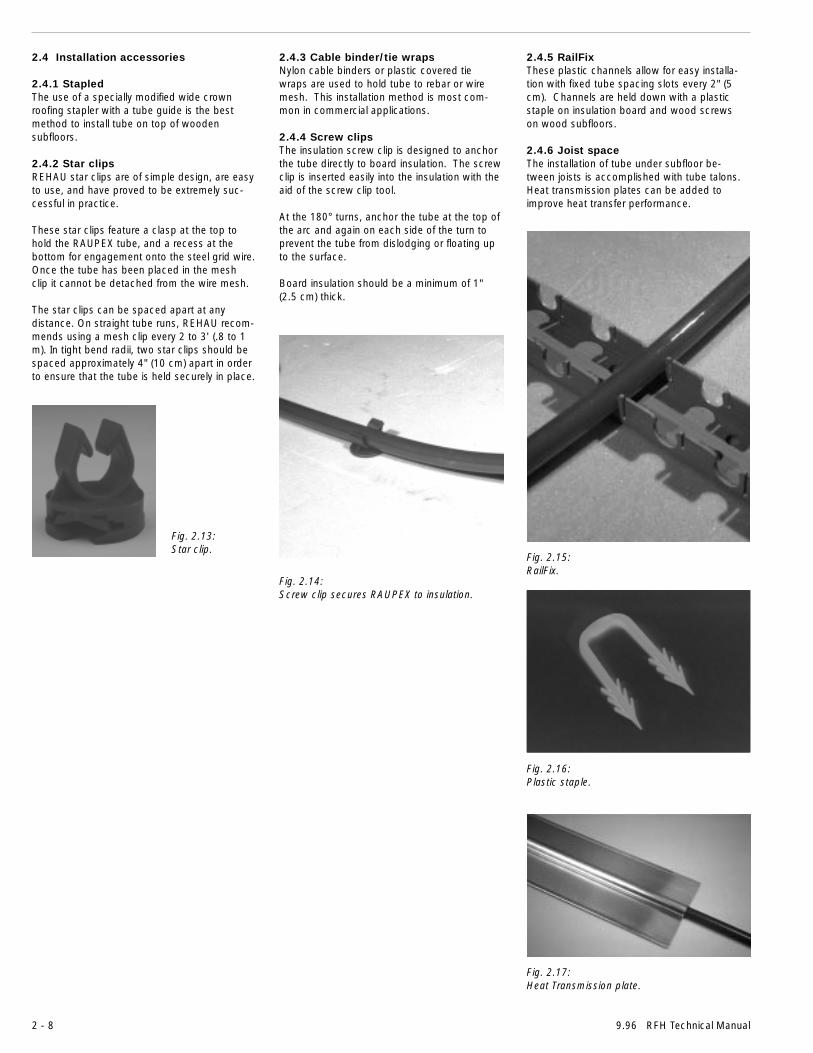
Fig. 2.14:Screw clip secures RAUPEX to insulation.
2.4 Installation accessories
2.4.1 StapledThe use of a specially modified wide crownroofing stapler with a tube guide is the bestmethod to install tube on top of woodensubfloors.
2.4.2 Star clipsREHAU star clips are of simple design, are easyto use, and have proved to be extremely suc-cessful in practice.
These star clips feature a clasp at the top tohold the RAUPEX tube, and a recess at thebottom for engagement onto the steel grid wire.Once the tube has been placed in the meshclip it cannot be detached from the wire mesh.
The star clips can be spaced apart at anydistance. On straight tube runs, REHAU recom-mends using a mesh clip every 2 to 3' (.8 to 1m). In tight bend radii, two star clips should bespaced approximately 4" (10 cm) apart in orderto ensure that the tube is held securely in place.
2.4.3 Cable binder/tie wrapsNylon cable binders or plastic covered tiewraps are used to hold tube to rebar or wiremesh. This installation method is most com-mon in commercial applications.
2.4.4 Screw clipsThe insulation screw clip is designed to anchorthe tube directly to board insulation. The screwclip is inserted easily into the insulation with theaid of the screw clip tool.
At the 180° turns, anchor the tube at the top ofthe arc and again on each side of the turn toprevent the tube from dislodging or floating upto the surface.
Board insulation should be a minimum of 1"(2.5 cm) thick.
2.4.5 RailFixThese plastic channels allow for easy installa-tion with fixed tube spacing slots every 2" (5cm). Channels are held down with a plasticstaple on insulation board and wood screwson wood subfloors.
2.4.6 Joist spaceThe installation of tube under subfloor be-tween joists is accomplished with tube talons.Heat transmission plates can be added toimprove heat transfer performance.
Fig. 2.13:Star clip.
Fig. 2.16:Plastic staple.
Fig. 2.15:RailFix.
Fig. 2.17:Heat Transmission plate.

2 - 9RFH Technical Manual 9.96
2.4.7 Control componentsREHAU offers control components for twobasic types of control systems. When inte-grated with existing heating systems or in anew system, these controls allow limitlesspossibilities and opportunities for the heatingsystem designer. These systems use constantwater temperature supply and/or electronicallymodulated water temperature supply.
Fig. 2.22:REHAU room thermostat with interchangeable°F & °C dial.
Fig. 2.20:Residential and commercial 4-way mixing valves.
Fig. 2.19:Remote bulb sensing injection control withinjection valve.
Fig. 2.18:Thermostatic mixing control with built-insensor.
Fig. 2.24:Mixing valve control motor.
Fig. 2.21:HKV manifold circuit actuator for individualcircuit control (on/off).
Fig. 2.23:Weather-compensating controller.

3 - 1RFH Technical Manual 9.96
3. Floor constructionFloor construction plays an important role in theperformance of the radiant floor heating sys-tem. The floor should allow for the heat fromthe tubes to dissipate readily and evenly up-ward to the heated space. Downward heatflow should be minimized through the use ofadequate insulation.
Radiant floor heating performs ideally whentubes are embedded in a “thermal mass” whichcompletely surrounds the tubes. This thermalmass could be concrete, gypsum-based prod-ucts or other thickset thermal mass materialsused in floor finishing. This is the pouredmethod of installation in which a poured ther-mal mass is applied over the tubes.
However, radiant floor heating also can workvery well in suspended wood frame floorswithout a poured thermal mass. This subfloormethod of installation places tubes next to theunderside of the subfloor. This method is idealfor retrofit or remodeling applications.
3.1 Applicable codesCertain radiant floor installation methods involvepenetrations through floor joists or other detailswhich may be governed by local codes. Checkwith applicable code authorities before installa-tion to determine specific requirements.
3.2 Floor materials and components
3.2.1 Thermal mass materialUnlike most heating equipment where perfor-mance can be measured in specific terms, theperformance of RFH is related directly to thestructure in which it is located. The heat outputand responsiveness of a radiant floor has moreto do with the thickness and the density of theconcrete, or other “thermal mass”, than almostany other part of the floor.
Gypsum-based thermal mass materials arecommonly used for radiant floor heating, as arevarious lightweight, portland-cement-basedtoppings. Most ready-mix concrete plants willsupply lightweight topping mixes if given aspecific “recipe”. Gypsum-based products aretypically obtained through licensed applicators.
Fig. 3.1:REHAU underfloor heating.
Fig. 3.2:Two poured methods.
Thermal mass which will be poured on a sus-pended wood floor must be poured so that thetop of tubes are at least 3/4" (19 mm) belowthe top finished surface of the thermal mass.This results in at least 1-1/2" (38 mm) thick-ness of thermal mass on most projects, andpossibly more. The wood subfloor should betreated with a sealant to prevent moisturepenetration from the thermal mass. Thermalmass materials that lose moisture too quicklyduring the curing process lose compositionstrength. Depending on the particular floor, thismay require deeper joists than would normallybe used to keep deflection within acceptablelimits. Deflection limits vary with the thermalmass; ask the supplier for the actual values.
Thermal conductivity of the thermal mass isgreatly affected by the amount of air entrainedin the mix, which acts as an insulator(Figure 4.3). All normal concrete contains someair, usually between 3% and 6%. By the addi-tion of various chemical agents, the amount ofair entrained in the concrete can be increasedor decreased to obtain desired qualities suchas density, workability, strength and durability.
3.2.2 Moisture barriersPolyethylene sheeting should be laid to preventupward migration of ground water in slab-on-grade applications. Consult flooring suppliersfor proper application of moisture barriersbeneath floor covering.
3 - 2 9.96 RFH Technical Manual
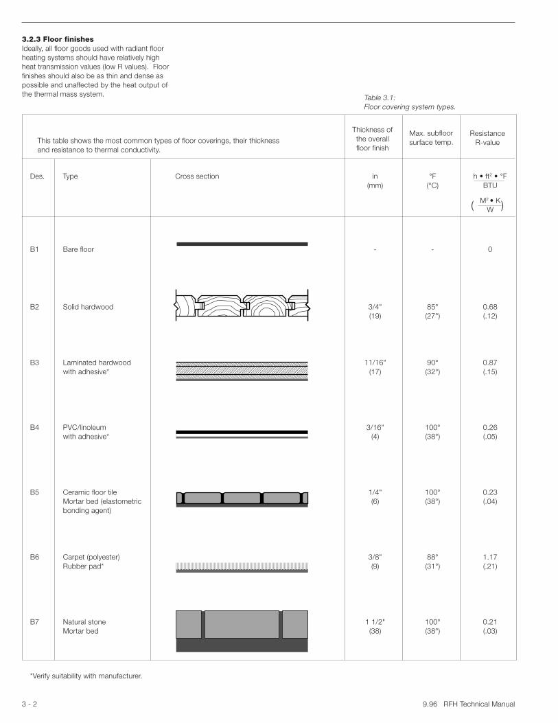
Des. Type Cross section in °F h • ft2 • °F(mm) (°C) BTU
M2 • KW
B1 Bare floor - - 0
B2 Solid hardwood 3/4" 85° 0.68(19) (27°) (.12)
B3 Laminated hardwood 11/16" 90° 0.87with adhesive* (17) (32°) (.15)
B4 PVC/linoleum 3/16" 100° 0.26with adhesive* (4) (38°) (.05)
B5 Ceramic floor tile 1/4" 100° 0.23Mortar bed (elastometric (6) (38°) (.04)bonding agent)
B6 Carpet (polyester) 3/8" 88° 1.17Rubber pad* (9) (31°) (.21)
B7 Natural stone 1 1/2" 100° 0.21Mortar bed (38) (38°) (.03)
*Verify suitability with manufacturer.
( )
This table shows the most common types of floor coverings, their thicknessand resistance to thermal conductivity.
Thickness ofthe overallfloor finish
Max. subfloorsurface temp.
ResistanceR-value
3.2.3 Floor finishesIdeally, all floor goods used with radiant floorheating systems should have relatively highheat transmission values (low R values). Floorfinishes should also be as thin and dense aspossible and unaffected by the heat output ofthe thermal mass system. Table 3.1:
Floor covering system types.

3 - 3RFH Technical Manual 9.96
Shrinkage gap
Cupping Crowning
3.2.4 Ceramic tile and natural stoneCeramic tile, pavers, marble and other stonefinishes are ideal for radiant floor surfaces. Anelastomeric adhesive between thermal massand tile/stone helps reduce movement andisolates cracks. Tile cement with high heatresistance should be used. Check with manu-facturers for recommendations when applyingover mortar beds, floor leveling compounds orother thermal mass.
3.2.5 HardwoodsMany successful RFH installations have beenperformed using both solid strip hardwood andlaminated flooring as well as wood flooringwhich has been press dried for dimensionalstability. Because wood readily absorbs andreleases moisture, special precautions shouldbe taken.
REHAU recommends consulting the NationalOak Flooring Manufacturers Association at(901)526-5016 or National Wood FlooringAssociation at (314)391-5161, as appropriate,for wood flooring over RFH systems. A fewissues to consider are:
- Boards with beveled edges and darker staincolors conceal shrinkage cracks betweenboards better.
- Quartersawn boards will shrink less thanplane sawn.
- The wider the floorboards are, the wider thegaps. Using narrower boards spreads theshrinkage over more gaps, resulting in lessnoticeable gaps.
- Laminated wood floors are less likely to “cup”or “crown”.
- Laminated wood floors designed to “float” onthe thermal mass (not directly glued) are alsoavailable and work well over radiant floorthermal mass.
No matter what type of wood flooring is used,proper RFH design, jobsite preparation andhandling of floor materials are essential.
If wood flooring is allowed to acclimate to thejobsite conditions for several weeks prior toinstallation, and is installed when humidityconditions are average for the area, dimen-sional changes will be minimized.
Installers should ensure that the RFH thermalmass is thoroughly cured before applying thehardwood boards.
3.2.6 Vinyl and linoleum goodsVinyl tiles are most affected by floor tempera-ture. Consult with the vendor for the maximumsubfloor surface temperature for both theadhesive and the covering.
Fig. 3.4:Beveled edges conceal shrinkage gaps.
Fig. 3.6:Cupping and crowning due to moisture.
Planesawn
Quartersawn
Fig. 3.5:Quartersawn and plane sawn wood boards.
Fig. 3.3:Natural stone floors are ideal.

3 - 4 9.96 RFH Technical Manual
3.2.7 Carpeting and paddingWhen selecting carpets for a radiant floorsurface, consider the following:
- Watch R-values, especially of the pad. Theuse of bonded or prime urethane carpet padmay seriously impair the performance ofradiant floor heating. Urethane carpets havea relatively high R-value and are designed toinsulate occupants from a cold floor typicallyfound with forced air systems.
- Consult with the vendor for the maximumsubfloor surface temperature for the carpetcovering system including adhesive limita-tions.
- There are various low R-value carpet padsavailable which are suitable for radiant flooruse.
3.3 Radiant floor assembly methodsThere are applications which call for the use ofeither a poured method or a subfloor method ofRFH installation. The decision for which installa-tion method is applicable is based on thebuilding’s structure and floor finish installationdetail. Figures 3.7 -3.11 detail various RFHinstallation techniques.
3.3.1 Poured methodsPoured RFH systems have several advantages.During the pour, the mix fills the joint betweenthe wall sole plate and the floor, reducing airinfiltration along exterior walls. Poured systemshave excellent heat transfer because the tubingis in complete contact with the thermal mass.This allows water temperatures 15°F (8°C) to20°F (11°C) cooler than the typical temperatureneeded in a typical dry system. The thermalmass tends to even out temperature fluctua-tions caused by on/off cycling of the heatsource. The thermal mass also dampenssound transmission through the floor systemand can improve the fire resistance rating of thefloor assembly.
Note that the minimum thickness for a pouredfloor above the top of the tubing is 3/4"(19 mm). Consult the poured floor applicatorfor recommended pour depth.
3.3.2 Subfloor methodsThe subfloor method of installing RFH systemsuses direct contact with the underside of thewood subfloor to transfer heat. The joist spacemethod of RFH heating is an example of thistechnique. Tubing is attached directly to theunderside of the subfloor in between the floorjoists. The use of reflective panels partiallysurrounding the tubing will increase the effi-ciency of heat transfer from RAUPEX tube tothe bottom of the subfloor.
Table 3.2:Overview of radiant floor heating system instal-lation methods. Indicates products requiredx
Indicates products suppliedby REHAU
Poured Subfloor
Installation Stapled Star Clip Cable RailFix RailFix JoistMethod Binders Insulation Space
Tie Wraps Screw Clip
Figure 3.9 3.7 3.7 3.8 3.10 3.11
Base Subfloor Grade Grade Grade Subfloor Subfloor
Insulation Blanket Rigid Rigid Rigid Blanket Blanket
Moisture Wood Sheet Sheet Sheet Wood NoneBarrier Sealer Sealer
Edge x x x x xInsulation
Manifold x x x x x xCabinet
Manifold x x x x x x
Tools Staple Rachet Screw HammerGun Tool Gun
Mounting Staples Star Cable RailFix Railfix TubeDevices Clip Binder/ Screw Clips Hangers
Tie Wraps PlasticStaples
Protection x x x x x xSleeve
Tube Cutter x x x x x x
RAUPEX x x x x x xTubing x
Expansion/ x x x x x xCompressionTools
Fittings x x x x x x
Manifold x x x x x xWrench
Purge and x x x x x xTest Kit
Thermal Mass x x x x x
Thermostats x x x x x x
Contol x x x x x xTransformer
Zone Controls x x x x x x
Pumps x x x x x x

3 - 5RFH Technical Manual 9.96
Slab - on - grade application (poured system)
3.4 Installation applications
3.4.1 Star clip and cable binder methodPlace wire mesh or rebar over the base mate-rial. If the base material is gravel, lay polyethyl-ene sheeting over gravel to prevent anyabrasion of the tube.
A better practice is to install a layer of 1"(25 mm) polystyrene insulation board on top ofthe polyethylene sheeting to minimize heatlosses downward. When installing wire meshon top of board insulation or flat substrate, usemesh support stands to raise the mesh so thatit is completely encased in the poured slab.Support rebar in the same manner.
RAUPEX tube is permanently attached to themesh with REHAU star clips according to thespacing required by the design. At the 180°turns, anchor the tubing at the top of the arcand again on each side of the turn to preventthe tubing from dislodging or floating up intothe pour.
Tubes are secured to rebar with plastic cablebinders which will not cause abrasion to thetube. Do not use wire ties without plasticcoating.
Fig. 3.7
���������������������������������������������
�������������������������
��������������
��������������
������
������
������
�����
����
��
����
�����
�����
����
��
Polyethylene sheeting (typ.)
1" insulation board (typ.)
Wire mesh support stands
Wire mesh (typ.)
Gravel
4" poured concrete slab (typ.)
Cable bindersOR
Star clips
��������������������
���������������������������������������1/2" board edge insulation
6"
6"

3 - 6 9.96 RFH Technical Manual
Fig. 3.8
Slab - on - grade application (poured system)
3.4.2 RailFix/insulation screw clipmethodInstall a layer of 1" (25 mm) polystyrene insula-tion board on top of the base material to mini-mize heat loss downward.
Install RailFix channels in a pattern to suit theintended tube layout, spacing the channels sothat the tube is anchored every 2 to 3'
(0.5 to 1 m). At the 180° turns, anchor the tubeat the top of the arc and again on each side ofthe turn with insulation screw clips whereRailFix is difficult to run. This prevents the tubefrom dislodging or floating up into the pour.RailFix provides tube spacing every2" (5 cm).
Anchor the RailFix channels to the board insula-tion using plastic staples.
������
�����
�����
�������������� Polyethylene sheeting (typ.)
1" insulation board (typ.)
Wire mesh (typ.)
Gravel
4" poured concrete slab (typ.)
�����
���
������
�������
������
���RailFix
Insulation screw clip
6"
���
�����
������
������
�����
����
��
����
�����
�����
����
Board edge insulation
��
�����
������
����
��
3 - 7RFH Technical Manual 9.96
Suspended wood floor application (poured system)
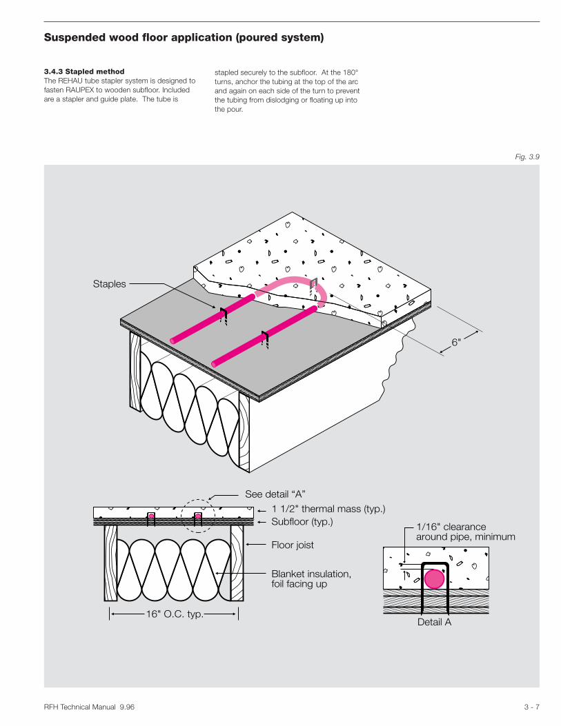
Fig. 3.9
3.4.3 Stapled methodThe REHAU tube stapler system is designed tofasten RAUPEX to wooden subfloor. Includedare a stapler and guide plate. The tube is
stapled securely to the subfloor. At the 180°turns, anchor the tubing at the top of the arcand again on each side of the turn to preventthe tubing from dislodging or floating up intothe pour.
Staples
��������
������
����
����������������������������
6"
See detail “A”
16" O.C. typ.
1 1/2" thermal mass (typ.)Subfloor (typ.)
Floor joist
Blanket insulation,foil facing up
Detail A
1/16" clearancearound pipe, minimum

3 - 8 9.96 RFH Technical Manual
Suspended wood floor application (poured system)
��
����
���
��
16" O.C. typ.
1 1/2" thermal mass (typ.)Subfloor (typ.)
Floor joist
Blanket insulation,foil facing up
Floor finish
����
���������������������
6"
RailFix
Fig. 3.10
3.4.4 RailFix methodInstall RailFix channels in a pattern to suit theintended tube layout, spacing the channels sothat the tube is anchored every 3' (1 m).
Anchor the RailFix channels to the subfloorusing suitable screws. At the 180° turns,anchor the tube at the top of the arc and againon each side of the turn with tube talons toprevent the tube from dislodging or floating upinto the pour.

3 - 9RFH Technical Manual 9.96
Joist space application (subfloor system)
16" O.C. typ.
Subfloor (typ.)
Floor joist
Blanket insulation
Transmission plate
Transmission plate
6"
3.4.5 Joist spaceFollowing the tube layout plan, secure theRAUPEX tube to the underside of the floorusing hangers, such as tube talons, or withheat transmission plates. When using plates,secure each plate to subfloor with screws (threeon each side). Do not cut plates.
During installation it will be necessary to loopthe tube from one joist cavity to anotherthrough holes cut into the joist.
Check local building codes before drilling ornotching through joists.
Connect the tube to the manifold and performtest.
Use of conductive panels will increase theefficiency of heat transfer from RAUPEX tube tothe bottom of subfloor.
Fig. 3.11

3 - 10 9.96 RFH Technical Manual
3.5 Thermal mass joints
3.5.1 Thermal mass movementsFloating thermal mass is always subject tomovement. This can be caused by shrinkageas a result of drying or expansion as a result oftemperature differences.
These movements mainly occur in the widthand length of floor surface. However, verticalmovement (bowing) may also be caused bydifferences in expansion at the surface andbase of the thermal mass layer.
Movements resulting from shrinkage occur onlyonce (when the thermal mass dries). Uncon-trolled cracking is avoided by limiting the size ofindividual thermal mass bays and by employingan appropriate arrangement of joints.
Movement resulting from temperature differ-ences can be estimated as follows:∆l = lo x ∝ x ∆t∆l = longitudinal expansion - in (mm)lo = thermal mass length - ft (m) ∝ = coefficient of longitudinal expansion 1/oF (1/oK) (value changes with thermal mass type)∆t = temperature difference oF (oK)
Example:Given: lo = 25 ft ∝ = 6.1 x 10⁻⁶ 1/oF ∆t = 55oF
Longitudinal expansion of the thermal masslayer is ∆l = .0084' or .10"
Planning and design must allow for absorptionof these movements.
3.5.2 Joint planThe location of joints is defined in the joint plan.This is generally specified by the architect andinfluences the planning of the tube layout of theradiant floor heating.
3.5.3 Arrangement of jointsWhere are joints necessary?-at the edge of the thermal mass to allow forthermal mass movement.
-around thermal mass bays.-areas = 430 ft2 (40 m2) (maximum).-side length = 26' (8 m) (maximum).-ratio of sides is less than 1:2.-along movement joints in the building struc-ture.
-in doorways.-for bays in L-shaped rooms.
Incorrect arrangement and design of joints arethe most common causes of thermal massdamage in floor structures.
Fig. 3.13:Arrangement of joints for heating circuits.
Movement joint
≤ 25
ft
≤ 25 ft
������
��������
RAUPEX
15"
Protection sleeve
15"
Fig. 3.12:Arrangement of expansion joints.
Fig. 3.14:Protective sleeving thru joint.
Incorrect Correct
3.5.4 Joint designHeating tube circuits and thermal mass baysmust be coordinated:
-Tube circuits should be planned and installedin such a way that they do not cross move-ment joints.
-These joints should only be crossed byconnection tubes.
-In these areas, the heating tubes must beprotected from shearing forces (at least 15"(40 cm) on either side of the joint) with pro-tective sleeve, such as REHAU corrugatedtube or other insulating channel (as shown inFigure 3.14).
-In the case of hard coverings (ceramic tiles),the joints must continue as far as the uppersurface of the floor finish.
Important: Consult floor finish installer forcoordination of thermal mass joint locations.

3 - 11RFH Technical Manual 9.96
Fig. 3.15:Contraction joint (joint cut into thermal mass).
3.5.5 Joint types
Contraction jointsContraction joints are cut with a trowel into thewet thermal mass down to about 1/3 to 1/2 ofthe thermal mass depth. Their purpose is toprevent uncontrolled cracking. They are onlycapable of absorbing movements resulting fromthermal mass shrinkage and are filled withsynthetic resin mortar or similar material aftercontraction has taken place.
Contraction joints frequently have a temporaryfunction only. They are used to further divideareas separated by movement joints. However,they are only suitable for use in heated thermalmasses to a limited extent:
-for bay sizes up to 16' x 16' = 256 ft2
(5 x 5 m = 25 m2).-only in cases where soft floor finishes areused - not in doorways.
1) Sub-floor2) Insulation layer3) Polyethylene membrane4) Heated thermal mass5) Contraction joint
Edge jointsThis type of joint is also a movement joint. Inthe REHAU radiant floor heating system, theyare formed by the edge insulating strip.
It is important that edge insulating strips arerigid enough to withstand compression fromthe wet thermal mass and soft enough toabsorb movements.
1) Brickwork2) Edge joint3) Sub-floor4) Insulation layer5) Polyethylene membrane6) Heated thermal mass
Fig. 3.16:Edge joint.
��������������������������������
����������������������
1 2 3 4 5 6
������������������������
������������������������
���������������������������������
1 2 3 4 5

3 - 12 9.96 RFH Technical Manual
Movement jointsMovement can be absorbed by special jointstructures. The following factors must beconsidered during joint design:
-Frequency of movement.-The degree of thermal mass expansioncaused by temperature.
-The requirements placed on sound andthermal insulation.
Movement joints are capable of absorbingmajor movement. They must be routed aroundthe thermal mass bays, used to separate differ-ent thermal mass bays/floor finishes in door-ways and must always be incorporated abovejoints in the building structure.
As a result of their construction, they are ca-pable of absorbing major horizontal and vertical(structural) movement.
Movement joints are positioned in accordancewith the joint plan and should have a width of atleast 3/8" (8 mm).
Whenever heating tubes cross movementjoints, a protective sleeve must encase the tubeas shown in Figure 3.14.
1) Sub-floor2) Insulation layer3) Polyethylene membrane4) Heated thermal mass5) Movement joint
Influence of joints on the floor finishesTo avoid cracking, each type of floor finish hasdifferent joint requirements.
Soft coverings(PVC, linoleum, carpet)Joint type and position, with the exception ofstructural joints, have minimal influence onthese floor finishes since they are generallycapable of absorbing movement.
1) Sub-floor2) Insulation layer3) Polyethylene membrane4) Heated thermal mass5) Movement joint6) Carpet
Fig. 3.17:Movement joint.
Fig. 3.18:Joint design for soft floor finishes.
������������������������
��������������������
���������������������������������
1 2 3 4 5
������������������������
��������������������
���������������������������������
1 2 3 4 65

3 - 13RFH Technical Manual 9.96
Hard coverings(tiles, stone floors)When laying tiles with mortar, you must allowfor the position of joints. Since the joint planonly indicates the approximate position ofjoints, the exact position of joints and corre-sponding tube laying pattern must be definedwith the floor layer before the thermal mass islaid.
1) Sub-floor2) Insulation layer3) Polyethylene membrane4) Heated thermal mass5) Movement joint6) Elastic joint compound7) Mortar bed8) Tiles
Hard coverings with separation layerAll joints can be arranged in the heated thermalmass as indicated in the joint plan, withouthaving to allow for joints in the floor covering.
1) Sub-floor2) Insulation layer3) Polyethylene membrane4) Heated thermal mass5) Movement joint6) Separation membrane7) Elastic joint compound8) Mortar bed9) Tiles
Fig. 3.19:Joints for hard floor finishes.
Fig. 3.20:Joints for hard floor finishes laid on separation layer.
������������������������
��������������������
���������������������������������
1 2 3 4 5 6 7 8
������������������
���������������
���������������������������������
1 2 3 4 5 6 7 8 9

3 - 14 9.96 RFH Technical Manual
Structural expansion jointsIrrespective of the type of floor finish, structuralexpansion joints must extend throughout thefloor structure as far as the surface of the floorfinish.
1) Sub-floor2) Insulation layer3) Polyethylene sheeting4) Heated thermal mass5) Structural expansion joint6) Movement joint7) Carpet
Fig. 3.21:Structural expansion joints.
������������������������
��������������������
���������������������������������
1 2 3 4 765
RFH Technical Manual 9.96 4 - 1
4. Planning and designThe planning and designing of a heating systeminvolves many objectives: economy, comfort,use of space and noise. Tougher laws requirestricter insulation regulations for structures,infiltration testing and heat loss design meth-ods. All new structures, along with their heat-ing systems, are to have an energy efficientdesign. RFH systems have little trouble meetingthese new guidelines.
For a designer with a hydronic heating systemsbackground, the planning and designing ofRFH systems is relatively simple. This chapterwill enable such a designer to specify RFHsystems for a pre-existing hydronically heatedbuilding or a new construction. If you do nothave prior experience with hydronic heatingsystems, please contact your local sales officelisted on the back of this manual.
4.1 PlanningIn order to do an accurate and complete job,the designer needs to start with a current set ofdrawings and specifications for the building, aclear understanding of any additional heatingsystems to be used, and the ability to discusscertain design issues with the owner and/or theowner’s agent.
combined in any combination and assigned tomanifold circuits to optimize circuit layoutpatterns and tubing lengths. Calculates re-quired water temperature, flow rate, and pres-sure drop across each circuit. Summarizestubing length requirements, flow rates andpressure drop figures.
4. Electronic Catalog - Allows for completeand accurate estimates using current catalogdata. System components displayed pictoriallyalong with article numbers, descriptions, andlist prices. List price multiplier can be specifiedand applied to all selected materials. Laborrate and time estimates can be included forcomplete quotations.
5. On-Line Help System - Allows designersto access technical and RFH WarmSourceinformation at any time during the design pro-cess. The complete REHAU RFH TechnicalManual is included within the “Help” system.RFH WarmSource system operating instruc-tions and sequences are also included.
6. Printed Output - The designer has theoption of printing the heat loss calculation, theRFH design, or the cost/material estimateseparately or in combination.
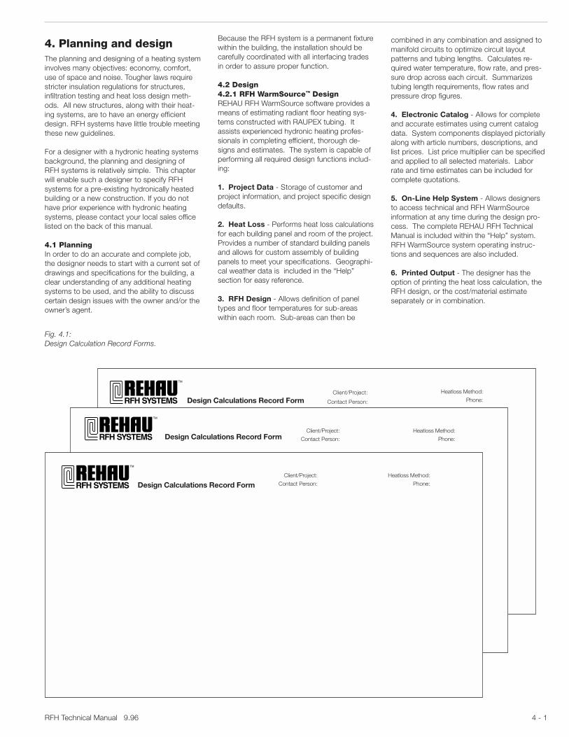
Fig. 4.1:Design Calculation Record Forms.
Because the RFH system is a permanent fixturewithin the building, the installation should becarefully coordinated with all interfacing tradesin order to assure proper function.
4.2 Design4.2.1 RFH WarmSource™ DesignREHAU RFH WarmSource software provides ameans of estimating radiant floor heating sys-tems constructed with RAUPEX tubing. Itassists experienced hydronic heating profes-sionals in completing efficient, thorough de-signs and estimates. The system is capable ofperforming all required design functions includ-ing:
1. Project Data - Storage of customer andproject information, and project specific designdefaults.
2. Heat Loss - Performs heat loss calculationsfor each building panel and room of the project.Provides a number of standard building panelsand allows for custom assembly of buildingpanels to meet your specifications. Geographi-cal weather data is included in the “Help”section for easy reference.
3. RFH Design - Allows definition of paneltypes and floor temperatures for sub-areaswithin each room. Sub-areas can then be
Design Calculations Record Form
Design Calculations Record Form
Design Calculations Record Form
Heatloss Method:
Phone:
Heatloss Method:
Phone:
Client/Project:
Contact Person:
Client/Project:
Contact Person:
Heatloss Method:
Phone:
Client/Project:
Contact Person:

9.96 RFH Technical Manual4 - 2
Tube location rules and recommenda-tions
- Note that areas under cabinets, windowseats, large appliances, raised hearths, stairs,etc. will typically not require heat.
- Start at outside walls. Keep tube a minimumof 6" (15 cm) away from the edge of the slaband all walls and other locations where plates,fixtures or built-ins might be fastened into thethermal mass floor.
- If flow through different circuits will be bal-anced by keeping all the circuits the samelength, circuit lengths should be kept within10% of each other.
- Keep circuits separate for different rooms forbetter room temperature control.
- Keep area types reasonably sized. Areas over450 ft2 (42 m2) are usually divided into twocircuits for 17 x 2 mm and 1/2" RAUPEX tube(reference maximum allowable circuit lengthon the RFH panel performance table in theDesign Supplement). For instance, whenusing 17 x 2 mm or 1/2" RAUPEX tube anoccupied area measuring 750 ft2 should bedivided into two 375 ft2 occupied areas.Larger diameter RAUPEX tubes allow forlarger area types (coverage). RAUPEX tubesizes 1" or 25 x 2.3 mm are used for aircrafthangars and large industrial buildings allowingfor 600' (183 m) circuit lengths for mostdesigns.
- Keep circuits for high heat loss areas and lowheat loss areas separate (exterior edges ofrooms separate from center and interioredges).
- When carpet and tile, for example, are in thesame zone with one circuit, the RFH designshould select the appropriate tube spacingand run the tube first through carpeted (orhighest R-value floor finish) areas.
6. Floor area per type - Measure the grossarea for each floor area type.
4.3.2 RFH panel heat requirement data
7. Required room temperature - Tempera-ture values required for RFH heated roomsprovide comfort at levels up to 3°F (1.7°C)lower than convection type heating systems.The owner of the building will have a specifictemperature level to maintain. Make sure todetermine this requirement. Most bathroomsare designed at 5°F (3°C) over the requiredroom temperature for the rest of the building.
8. Total heat required - The required heatcapacity for a building project is determined byperforming a heat loss calculation. Various heatloss calculation standards are used throughoutNorth America.
Examples of heat loss calculation methods:- ASHRAE Fundamentals Handbook
(Manual “J” Method)- Hydronics Institute IBR H-22 Guide- R-2000 Canadian Home Builders Association- HOT2000 Program- CSA Standard F280-M1986
Fig. 4.2:Resultant floor surface temperature.
4.2.2 Design Calculation Record FormsREHAU "Design Calculation Record Forms"(DCRFs) have been developed to lead thedesigner through the RFH design process.These three-page forms are offered on11" x 17" pads. Individual sheets may bedetached for photocopying.
The DCRFs provide the following information:Page 1:Room DataRFH Panel Heat Requirement DataRFH Panel Design
Page 2:RFH Panel Performance DataRFH Panel Tube Requirements
Page 3:Pump Sizing DataBalance Valve Setting Data
The Design Supplement to this manual pro-vides REHAU RFH panel performance tablesand graphs for common North American build-ing construction methods.
4.3 Design Calculation Record Formscolumn definitions
4.3.1 Room dataRoom data is obtained from the plans and theowner and/or owner’s agent. It is very importantto organize the rooms by floor level and/orcommon manifold location.
1. Floor level - The floor level will be identifiedas 1st, 2nd, 3rd, etc. It is important to know thefloor level when organizing manifolds, commonfloor structures and controls.
2. Room no. - Each room should be identifiedwith a room number. Reference the plan forpreassigned room numbers or assign roomnumbers as required.
3. Room function - Reference the room'spurpose: Dining, Kitchen, Living, Bath, etc.Note special conditions.
4. Room area - Total gross area within theperimeters of the room’s walls.
5. Floor area type - Typical Floor Area Types:RFH Perimeter Area - PRFH Occupied Area - ORFH Distribution - DNO RFH - X
When RFH is used in a typical floor area, themost efficient designs separate the perimeterzone along the outside walls and occupiedarea(s) in the center of the room. The non-heated areas need to be identified to correctthe total RFH panel heat capacity requirementfor the room. Where distribution pipes runthrough one room to another or to another floorarea type within a room, this space must beallocated as “distribution” (heated space withun-insulated tubes). When using insulatedtubes, this floor area type is considered thesame as a NO-RFH (X) floor area type.
Sub-floor surface temperature
80 85 100
2.25 2.502.001.75
1.501.25
1.00
.75
.50
.25
90 95 105 110 115 120 135125 130 140 145 150
Res
ulta
nt fl
oor
surf
ace
tem
pera
ture
70
85
80
75
90
95
115
110
105
120
125
130
100
Floor finish R-value
Room temperature 68°F (20°C)54.4
51.7
48.9
46.1
43.3
40.6
37.8
35.0
32.2
29.4
26.7
23.9
21.1
°C °F
26.7 29.4 32.2 35.0 37.8 40.6 43.3 46.1 48.9 51.7 54.4 57.2 60.0 62.8 65.6
°F
°C

RFH Technical Manual 9.96 4 - 3
Energy conservation laws related to heat lossevaluation have been adopted by a few NorthAmerican states and provinces. These newlaws require the use of specific heat loss pro-grams. Determine the applicable laws bychecking with the local municipality and/orbuilding inspection department. In most com-mercial and industrial applications, the requiredheat capacity will be calculated by a registeredarchitect or engineer.
Detailed heat loss calculations must be done asaccurately as possible. Oversized boilers willshort cycle and create large temperatureswings in the system supply water temperature,reducing efficiency. Oversized pumps are proneto cavitation, creating excess noise and wear inthe system.
RFH systems may be combined with otherhydronic heating systems such as fan coils orradiators. Such “integrated” systems may alsobe required to meet special building require-ments, such as forced ventilation or pressuriza-tion in hospitals, while also providing comfortheating. The designer for such combinedsystems should carefully evaluate the interac-tion of each of the systems with respect tocontrol and load diversity.
The DCRF provides a split column (col. 8) torecord these values. The top of the column isthe total heat required (btuh) and the bottom ofthe column is for the unit/area value for the totalheat required (btuh/ft2). When the unit/areavalue for the room seems excessive based onthe heat loss calculation standard, it is impor-tant that the designer evaluate infiltrationlosses, glass area and type of windows and theneed for heating the air space above a certainlevel in the room. RFH output typically results invery little air stratification and infiltration heatloss. As a result, RFH has proven to be thepreferred method to heat large structures suchas aircraft hangars.
9. Floor finish - Reference the type of floorfinish: Tile, Oak, Marble, Slate, Thin Carpet, etc.Identify complimentary components like carpetpads, mastics and vapor barriers that willcontribute to the heat resistance.
10. Floor finish thickness - Identify totalthicknesses for the floor finish components.
11. Floor finish total resistence (R-value) -Check with the vendor of the floor finish for R-values of all additional components of the floorfinish - adhesive, grout, carpet pad, etc.
12. Thermal mass maximum allowablesurface temperature - The maximum allow-able surface temperature for a thermal mass isdirectly related to the maximum allowableexposure temperature for the planned floorfinish. Floor finishes each have their own tem-perature limits. Wood floors are the most sensi-tive to thermal mass surface temperatures.Verify acceptable temperature limits with thevendor of the planned floor finish and installa-tion system (adhesive/grout). See Table 3.1 foracceptable limits.
13. Resulting or allowable floor surfacetemperature - Floor surface temperatures aredirectly the result of the maximum allowablethermal mass surface temperature (col. 12) andthe advisable temperature exposure limitationsfor human comfort. The floor surface tempera-ture should never exceed 85°F (29°C) in theoccupied areas, 91°F (33°C) for bathroomsand 95°F (35°C) for perimeter zones. Whenmaximum allowable thermal mass surfacetemperatures fall below the acceptable tem-peratures for human comfort for different paneltypes, the resulting surface temperature for thefloor finish can be found by using the “FloorSurface Temperature” column of the appropri-ate design table found in the Design Supple-ment. Figure 4.2 is a graph of resultant floorsurface temperature for various sub-floor tem-peratures and floor finish R-values at a roomtemperature of 68°F (20°C).
14. Available RFH panel unit/area heat -The amount of heat available from an RFHpanel is directly related to the maximum allow-able floor surface temperature, required roomtemperature and the film coefficient of the airacross the surface of the RFH panel. The maxi-mum available panel unit/area heat is calculatedby multiplying the temperature difference be-tween the ambient air and the maximum allow-able floor surface temperature by panel area foreach panel by 1.9 btuh/ft2 °F. If the result ofthis step is below the heat required, plan oneither adding supplemental heat or reducingthe heat load through energy conservationmeasures for the building.
15. Total available RFH panel area heat -This value is used to show the heat capacity ofeach area type with the maximum allowablefloor surface temperature.
16. Total available RFH panel heat - Tocalculate total RFH heat available for the room,add all total available RFH panel area heats(col. 15) for each total available RFH panel areafor the room. The final design most likely willnot run the floor temperatures to the maximumlevels. This value will show the designer veryquickly if RFH will provide the heat outputrequired when compared to the total heatrequired for the room.
17. Residual heat (+ or -) - Subtract thedifference between the total heat required(col. 8) and the total available RFH panel heat(col. 16).
Density, oven dry10 30 50 70 90
160 480 800 1120 1440kg/m3
lb/ft3
The
rmal
co
nduc
tivi
ty, b
tu/h
r/in
/sq
ft/°F
Wat
t p
er m°C
0
1
2
3
4
0
0.1
0.2
0.3
0.4
0.5Note: Corresponding thermal conductivity for normal density concrete is generally between 9 and 12 Btu/hr/in/sq ft/°F or between 1.3 and 1.7 watt per m°C.
Fig. 4.3:R - value for light weight thermal mass materials.

9.96 RFH Technical Manual4 - 4
23. Insulation thickness - Most R-values forinsulation systems are given for the blanket orper inch for boards. The thickness of the insula-tion is required to calculate the total R-value forthe insulation. If the insulation system beingused has specific R-values for each thickness,skip this column.
24. Insulation total resistence (R-value) -This R-value is either given by the manufacturerof the insulation system or calculated knowingthe total thickness and the R-value per inch.
4.3.4 RFH panel performance data
25. Room no. - Corresponding number forroom from page one.
26. RAUPEX tube size selected - Size oftube being used in the RFH panel. Generallytube size is determined by average circuitlengths required for the building/zone. 17 mmand 1/2" tubing are used for residential radiantfloor heating applications. 20 mm, 25 mm,3/4" and 1" are used for commercial and indus-trial applications and snow melting.
27. REHAU RFH panel performance table/graph - The Design Supplement provides RFHperformance tables and graphs for commonRFH panel designs for North America. Pageone of the Design Supplement provides anindex for these tables/graphs. The performancetables and graphs assume 15% downward lossfor poured installations and 25% downwardloss for subfloor installations.
The following naming convention is used tocatalog the performance tables and graphs:
P\LW\1.50\1.00\5.00\0.25\1
Example:Identify the REHAU RFH panel perfor-mance table for a 4" concrete slab-on-grade with 2" of stryrofoam insulationwith 17 x 2 mm RAUPEX tube installed3.50" deep in the thermal mass with allthe following R - values:
R-Value for Insulation = 10R-Value for Floor Finish = 0.00
(No Floor Finish)
W\AG\4.00\3.5\10\0.00\17
In cases where the DCRF form specifiesinformation for an RFH panel perfor-mance table/graph that REHAU has notpublished, order one using the RFHSystems "Special Request" form in theDesign Supplement. Write “SPECIAL” incolumn 27.
4.3.3 RFH panel design
18. RFH panel type - RFH panels are eitherdesigned around the poured or subfloormethod. The poured method is based on theuse of a cementitious type thermal mass. Thesubfloor method is based on the use of thetube mounted to the underside of the sub-floorwith insulation 2" (5 cm) below the tube toreflect the heat upward.
19. Thermal mass type - The thermal mass isgenerally made from cementitious materials(Portland/Gypsum). The thermal mass will haveboth structural and weight requirements. RFHpanels depend on the thermal mass to transferthe heat travelling through the heating water inthe tubes to the room requiring heat. Thermalmass system types are typically available fromconcrete and floor leveling suppliers or licensedapplicators of Gypsum products. Typical abbre-viations used to identify thermal mass typesare: LW for light weight, AG for aggregate, GYPfor Gypsum, or JS for joist space method.
20. Thermal mass thickness - The thicknessof the thermal mass is decided by the structuralrequirements, building floor height, variancerequirements of the RFH panel design andthermal mass manufacturers’ requirements.Conductive floor finishes over a thin thermalmass (1.5" or 38 mm) will require tube with aclose spacing to prevent uneven heat along thesurface. The thickness of the thermal mass alsoaffects the time period required to bring theRFH panel to heating capacity.
21. Depth of thermal mass over tube - Thedepth of the tube in the thermal mass is re-quired to determine the heat resistance upwardwith regard to the heat loss downward. REHAURFH panel performance tables/graphs in theDesign Supplement are provided for specifiedtube depths. The depth is measured from thetop of the thermal mass to the top of the tube.
22. Insulation type - Insulation systems arevery important for maximizing RFH panel perfor-mance. Roughly 15% of the RFH panel heatoutput can be taken as a basis for calculationof downward heat loss with insulation rated atR-5.
Polystyrene, styrofoam and fiberglass are themost common building insulation products.Polystyrene and styrofoam come in board form,from 1/2" to 4" (12 mm - 102 mm). Board forminsulation is used with poured RFH panel instal-lations. Fiberglass insulation comes rolled up inblanket form. The most common use for “batt”insulation is between floor joists, wall studs andceiling/roof joists (attic space). When the fiber-glass insulation has a reflective barrier, thereflective barrier will be closest to the tube forsubfloor RFH panel construction.
Col Category26 RAUPEX tube size selected11 Floor finish total resistance (R-value)24 Insulation total resistance (R-value)21 Depth of thermal mass over tube20 Thermal mass thickness19 Thermal mass type
LW - Light weight, AG - Aggregate,GYP - Gypsum, JS - Joist space
18 RFH panel type pour =P subfloor = S
By column numbers: 18\19\20\21\24\11\26
In cases where the DCRF form specifies information for an RFH panel performancetable/graph that REHAU has not published,order one using the RFH Systems "SpecialRequest" form in the Design Supplement. Write“SPECIAL” in column 27.

RFH Technical Manual 9.96 4 - 5
Fig. 4.4:REHAU RFH performance table method -Once the correct table has been selected, use the MHWT, the room temperature and the maximumallowable surface temperature to find the RFH panel heat capacity. The designer, through experi-ence, will select the tube spacing which provides evenly heated surfaces and optimized circuitlengths.
Average temperature of water in tube - supply temperature and return temperature divided by 2 Tube spacing - center line to center line
Tube required per square foot of floor Heat output per square foot of floor
Floor surface temperatureMaximum square feet covered based on tube length and spacing
Maximum circuit length for capacity and tube spacing requirement
Ambient room temperature
2 6.0 14 75 131 787 9 77 131 7874 3.0 12 74 262 787 8 76 262 787
80 6 2.0 10 73 393 787 7 75 393 7878 1.5 9 72 525 787 6 75 525 787
10 1.2 8 72 656 787 5 75 656 78712 1.0 7 727 787 787 5 74 787 787
90
100
110
SpecificTube
Require.
ft/ft2
DistanceBetween
Tubes
in
Capacity
btuh/ft2
Max.HeatingCircuitArea
ft2
Capacity
btuh/ft2
Max.HeatingCircuitArea
ft2
Max.HeatingCircuitLength
ft
Max.HeatingCircuitLength
ft
FloorSurfaceTemp.
°F
FloorSurfaceTemp.
°F
MeanHeatingWaterTemp.
°F
1 2 3 4 5 6 7 8 9 10 11
Room Setpoint = 72° FRoom Setpoint = 68° F
Before beginning your calculations, you must already haveKNOWNS:
1. Heat requirement for room2. Floor area of room (available)3. Desired room temperature4. Type of floor construction and floor covering
Find correct corresponding table depending onType of floor construction and floor covering
Use the following steps to supply your UNKNOWNS.1. Calculate Capacity (from knowns) Heat requirement divided by floor area2. Select Mean Heating Water Temperature
Note: There are varying options available depending onyour choice of Mean Heating Water Temperature.
All other variables are a result of table specifications.
Table: P\AG\4.00\3.5\10\0.00\17
Example:
12,000 btuh1,200 ft2
68° FConcrete over subbase floor construction,Thin carpet floor covering
12,000 btuh1,200 ft2
Selected 80°F Mean Heating Water Temp.Find 10 btuh/ft2 (capacity) and read left on table toRequired Spacing - 6" andSpecific Tube Require. - 2.0 ft/ft2
Select Ambient Room Temperature - 68°F (known)Read across table to find:Floor Temperature - 73°FMax. Heating Circuit Area - 393 ft2
Max. Heating Circuit Length - 787 ft2
= 10 btuh/ft2

9.96 RFH Technical Manual4 - 6
Example:(A) Determine the Mean Heating Water Temperature (MHWT) from the performance graph,given the following DCRF values;
col. 7 (Required Room Temp.): 68°Fcol. 8 (Total Heat Required Per Area): 24 btuh/ft2
col. 11(Floor Finish Total Resistance): R=1.05col. 26(RAUPEX Tube Size Selected): 17 mm
(B) Using the performance graph shown in Figure 4.5 (or performance graph appropriate foryour design) perform the following:
Step 1: Draw a horizontal line starting at R=1.05 (lower left side vertical axis) over tothe 4" tube spacing curve (see note 1).
Step 2: Draw a horizontal line starting at 24 btuh/ft2 (upper left side vertical axis)over to the right side vertical axis.
Step 3: Draw a vertical line perpendicular to the 4" spacing intersection point, found inStep 1, up to the horizontal line found in Step 2. At the intersection of these twolines, locate the nearest sloped (MHWT) line. Follow along this sloped line overto the right side vertical axis. FOR THIS EXAMPLE, we find that the value is 52°F.This value of 52°F is the MHWT over-temperature.
Step 4: Calculate MHWT from the following;MHWT= 52°F (over-temperature) + 68°F (room temperature)MHWT= 120°F
Step 5: Enter this MHWT into DCRF column 29.note 1: If necessary, repeat steps 1-4 with various tube spacings to optimize MHWT.
Fig. 4.5:REHAU RFH performance graph.
28. Heating water temperature spread - Thisis the temperature difference between the supplyand return heating water to the RFH panel. Mosttypical hydronic designs are based on a tempera-ture spread of 20°F (11°C) or 10°F (6°C). RE-HAU RFH panel performance tables/graphs arebased on 20°F (11°C).
29. Required mean heating water tempera-ture per room (MHWT) - The definition of meanheating water temperature (MHWT)is: the aver-age temperature for the supply and return heat-ing water to the RFH panel. The temperatureselection should be based on economy andefficiency of design. Temperature selection,however, will also be constrained by the maxi-mum allowable thermal mass surface tempera-ture, maximum allowable floor surfacetemperature and heat output required for theroom. In certain instances the maximum supplywater temperature is limited (lower) due to theheat output of the heat source. In this case, thetemperature limit of the heating source estab-lishes the parameters for selecting the MHWT.Use of the lowest heating water temperature thatwill provide the required floor surface temperaturewill also minimize thermal stress on slabs andfloor coverings, and minimize overshooting ofdesired room temperatures. Proper heating watercontrol design will provide the correct MHWT forzone or building requirements. Providing specificMHWT for designated manifolds is the way tocorrect for heat capacity which varies due to floorcovering or heat loss requirements of specificrooms.
The first step in selecting MHWT is to evaluatethe MHWT requirements for each room based onthe total unit/area heat required(col. 8) and available RFH panel unit/area heat(col. 14 ). Using the RFH panel performance tableor graph selected in column 27, select “reason-able” tube spacings and MHWTs. MHWTs rang-ing from 80° to 130°F (27° to 60°C) are availablewith the corresponding RFH panel heat outputvalues and tube spacings.
30. Selected mean heating water tempera-ture per bldg/zone - Determining the MHWT fora building or a zone in a building is done by eitherthe “Highest MHWT” method or the “AverageMHWT” method in conjunction with the availableheat from the heat source. Always verify thatfloor surface temperatures remain below maxi-mum values for each floor area type.
Highest MHWT Method: Select the highestMHWT value from column 29 and use this MHWTfor all the rooms in the building or zone.
Averaging method: The averaging method isbased on evaluating the MHWT values for theentire building or zone simultaneously. If a major-ity of the rooms will work with the MHWT se-lected, then the designer can look at providingthe remaining rooms with the additional heatrequired through supplemental heat or reorganiz-ing the heating distribution system to providespecified MHWT groupings through zoning. Theaveraging method provides the lowest MHWT.
5
10
15
20
25
30
35
40
45
50
55
2.01.81.61.41.21.0.8.6.4.20
10
20
30
40
50
60
70
Distance between tubes12" 10" 8" 6" 4"
Mea
n he
atin
g w
ater
“ov
er-t
empe
ratu
re” °F
(mea
n ho
t w
ater
tem
p –
room
tem
p)
Cap
acity
btu
h/ft
2
Floo
r fin
ish
resi
stan
ce“R
-Val
ue”
17 x 2 mm tube

RFH Technical Manual 9.96 4 - 7
31. RAUPEX tube spacing - The requiredtube spacing is determined by the available andremaining RFH panel unit/area heat capacity,maximum floor surface temperature allowedand the MHWT.
The following considerations affect tube spac-ing:
- Closer tube spacing allows for a lower MHWT
- Tiles are often selected as the floor coveringwith underfloor radiant heating systems.Closer tube spacing will prevent noticeabledifferences in floor surface temperature. Fornormal comfort applications, spacing shouldbe no greater than 12" (30 cm) on center toavoid cold spots.
- The closer the tube spacing, the smaller thearea which can be served by one heatingcircuit.
- Tubing should be at least 6" (15 cm) from thefinished wall surface and nailing surfaces.
REHAU recommends that tube spacing beselected to provide the most efficient system,i.e., the lowest hot water temperature, consid-ering the tube layout and tube length con-straints noted above.
32. Resultant floor surface temperature -Resulting surface temperatures as referencedfrom RFH panel performance table/graph.
33. Available RFH panel unit/area heatcapacity - This is the first iteration to determinethe RFH panel capabilities for a room. If theroom has a perimeter area, it is best to maxi-mize the allowable floor surface temperature tomeet as much of the heat load requirement forthe room as possible.
34. Resulting RFH panel area heat output -Determined by multiplying the available RFHpanel heat capacity (col. 33) by the availableRFH floor area (col. 6).
35. Room heat capacity balance (+ or -) -Subtract the resulting area heat output from thetotal heat required. This value represents theremaining heat required for this room.
36. Total remaining RFH panel area - Avail-able RFH panel area with heat capacity.
37. Remaining RFH panel unit/area heatcapacity required - Knowing the remainingavailable RFH panel area and the heat capacity,this value provides the required unit/area heatcapacity. This value is important to the designerto understand the remaining distribution of theRFH panel areas for the room.
38. Remaining RFH panel unit/area heatcapacity available - Using the performancetable/graph, determine the available unit/areaheat capacity.
39. Resulting RFH panel area heat output- This value represents the total output ofeach of the remaining RFH panel area types.
40. Total RFH panel heat output - The totaloutput of all the RFH panel area types for theroom.
41. Supplemental heat capacity required(remainder) - The RFH panel output com-pared to the total heat required for the room.
4.3.5 RFH panel tube requirements
42. RAUPEX tube requirement factor -Circuit tube length required per unit RFHpanel area. (See Fig. 4.6)
43. Maximum allowable RAUPEX tubecircuit length - The maximum allowablecircuit length is based on design conditionsfor temperature and heat capacity with amaximum pressure loss of 10 feet of head.
44. Length of RAUPEX tube circuit tails -The host RFH distribution manifold and theRFH heating panels are usually located indifferent areas of a building. The tubes to andfrom the RFH distribution manifold to the RFHpanel are called circuit tails. The length of thesecircuit tails must be added to the RFH paneltube circuit length to calculate the total pres-sure requirement for the tube circuit.
45. RFH panel RAUPEX tube circuit length -Calculate total length of tubing required by theRFH panel by multiplying the tube requirmentfactor by the panel area.
46. Combined RAUPEX tube circuit length -The total length of tube required to make up thecircuit effective length and circuit tails. The totalallowable circuit length is based on the maxi-mum allowable tube circuit length. REHAUoffers a full range of tube diameters to allow thedesigner, with the proper thermal mass thick-ness, to change tube sizes for tube circuitlength requirements.
47. Number of heating circuits - Total num-ber of tube circuits required to supply RFHpanels for this room.
Select zones. A zone is an area served by oneor more tube circuits, and which will be con-trolled separately. Areas which will have dis-similar heat loss rates should be zonedseparately. Areas with similar floor constructionand finishes and with similar heat loss ratesshould be combined into the same zones.
Fig. 4.7:Distribution for RFH.
Fig. 4.6:Tube requirement factor chart.
Tube Tube requirement factorspacing (Tube required
per square foot)
2" 6 feet
4" 3 feet
6" 2 feet
8" 1.5 feet
10" 1.2 feet
12" 1 foot

9.96 RFH Technical Manual4 - 8
.01
.02
.03
.04
.05
.07
.2
.3
.4
.5
.7
1
2
3457
10
20
30405070
.1
.01 .02 .03 .05 .07 .2 .3 .5 .7 1 2 3 5 7 10010 20020 30030 4050.1
Pressure loss in feet of head/100' tube
Flo
w in
gp
m
Metric tube sizes
32mm
25mm
20mm
17mm
ASTM tube sizes
Velocity FPS
1"
3/4"
1/2"
2
1
34
56
Fig. 4.8:Pressure drop table for REHAU heating tubes.

RFH Technical Manual 9.96 4 - 9
4.3.7 Pump sizing data - Using the flow ratesfor each circuit from DCRF Page 3, enter thepressure loss chart (Figure 4.8) until you inter-sect the tube size line. Then follow the linevertically down to the pressure loss.
The result is a pressure loss in feet of head per100 feet of tube. Measure the lengths of tube inthe circuit, divide by 100, and multiply by thefriction drop values from the chart to arrive atthe total circuit pressure loss. The total energyrequirement of a system comprising severalbranch circuits is determined by the circuithaving the greatest pressure drop, i.e., the“worst case circuit”.
If pressure drop for any circuit is excessive(greater than 10 feet of head per circuit), reviseeither the zoning, the number of circuits, thetube size or the flow rate. If the tube size ortube lengths change, recalculate the pressureloss and corresponding water temperatures.
When all circuit pressure drops are withinacceptable ranges, estimate the pressurelosses through balancing and shut-off valves,and find total pressure drops. Use Figures 4.9and 4.10 to estimate valve losses.
For each manifold, add the flow rates for allcircuits served from the manifold. Size thecirculating pump using the sum of the flows,and the greatest of the pressure requirementsserved by that circuit.
Pump manufactures provide pump perfor-mance curves. The designer can compare theRFH requirements with the pump characteris-tics to optimize selection. Selection of pumpsfor closed circuit heating systems should bedone through careful matching of the pumpoperating characteristics to the system operat-ing requirements.
Pumps used for RFH systems are generallysmall, in-line circulator, (centrifugal) type. Circu-lating pumps should have a flat pressure headcharacteristic and should be selected to oper-ate slightly to the left of the mid point of theirperformance curve. Pumps with steep perfor-mance curves should not be used since theytend to limit system flow rates.
4.3.8 Adjusting manifold balancingvalves - With the pressure loss data for eachcircuit on a manifold, the designer can deter-mine the difference between the greatest pres-sure loss and the remaining. Then use Fig. 4.10to determine the appropriate number of turnsfor each balancing valve. Follow specific in-structions supplied with the manifold.
4.3.9 Thermal mass quantities - The amountof thermal mass required for the project is easilycalculated by knowing the thickness of thethermal mass, the volume of space the RFHcomponents will consume in the thickness ofthe thermal mass, and the amount of additionalthermal mass that will be required to fill in lowpoints and pockets. Thermal mass quantitiesare normally specified in cubic yards or cubicmeters.
4.3.10 Control quantities - A typical roomwith RFH will have a thermostat to control thecomfort and valve actuator at the manifold toopen and close the circuit isolation valve. Inaddition, the circuit may have specialized con-trols such as a separate water temperatureregulator. One room with three circuits mayhave one thermostat with three circuit heads.
Usually, supply and return water temperaturesare limited by the heat source. A condensingtype boiler, electric boiler or heat pump can beoperated at very low supply water tempera-tures. In contrast, conventional oil- or gas-firedboilers usually require a minimum return watertemperature of 130°F (54°C) in order to preventcondensation of the flue gases and subsequentcorrosion and blockage of the boiler heat ex-changer and chimney. However, radiant floorheating systems require water temperatureslower than 130°F (54°C).
The best way to protect both the boiler and thetube is to mix the cooler radiant floor systemreturn water with the boiler supply water. Thismixing process can be controlled by the follow-ing generally accepted methods:- 3- or 4-way mixing valve with or without
outdoor reset control.- Hot water injection system using a fixed
speed pump.- Hot water injection system using variable
speed pump.
The use of the building can also affect thezoning of the radiant floor heating.
- Residential. Residents will typically use differ-ent rooms within a home at different times ofthe day, such as bedrooms versus kitchens.Rooms that are used together should bezoned together. Rooms that are not used forsubstantial periods of time, such as formaldining areas, should be zoned separately, sothat they may be set back to conserve energyand reduce operating costs.
- Commercial. Use of commercial buildingsusually includes one or two types of activities,such as eating or shopping, and may changedepending on the turnover. Zoning should beversatile enough to accommodate changes inthese use patterns.
- Industrial. The industrial process usuallydetermines the zoning, and may also containlarge pieces of machinery which may add tothe heat in the room. Zoning for industrialapplications should be determined by thedesign engineer according to the consider-ations which apply.
48. Manifold station label - Identification oftube circuit. Suggested naming convention: A1- “A” stands for the 1st manifold and “1” standsfor the 1st tube circuit. Tube circuits should belabeled from left to right on the manifold. An-other example: The 6th tube circuit from the lefton the third manifold would be called C6.
4.3.6 Required water flow rate - Quantity ofheating water required to support an RFH panelarea type.
Water flow rate is calculated for each circuitusing RFH panel heat output for the zonesserved by the circuit and the spreads betweensupply and return water temperatures. Theequation is as follows:
Flow =RFH Panel Unit/Area Heat Output (btuh)
.85 x 5001 x Heating Water Temperature Spread
where:Flow - gpmTemperature - °FHeating Water Temperature Spread: (ts- tr)ts - supply water temperaturetr - return water temperature.85 - compensation for downward RFH panel heat loss (for 15% downward panel heat loss)
Notes:1 500 = (8.34 lb/gal of water) (60 min/hr)(1)
(a) (b)
(a) 8.34 = approximate density of water at RFH water temperatures.(b) 1 = heat capacity of water. Values (a) and (b)
will change when adding antifreeze.

9.96 RFH Technical Manual4 - 10
Fig. 4.9:Pressure loss table for flow valves in the heat-ing circuit distribution manifold. The flow valvesin the heating circuit distribution manifoldshould be fully open to accommodate the flowthrough individual heating circuits and stillgenerate a pressure loss. However, their pres-sure loss must be included in determining thetotal pressure loss of a heating circuit. Thistable can also be used to determine pressureloss for a specific volume flow.
Example:A heating circuit has a flow rate of .44 gpm (100 l/h). The pressure loss that will occurin the flow valve amounts to .05 psi (3.55 mbar) determined from the fully open curve.This value is then added to the pressure loss derived from Figure 4.9.
Pre
ssur
e lo
ss P
Pft mbar
.031 .044 .088 .132 .220 .440 .880 1.32 2.20 4.40 8.80 13.20
7 10 20 30 50 100 200 300 500 1000 2000 3000l/h
gpm
Volume flow V
13.4 400
10.0 300
6.70 200
3.35 100
1.67 50
1.00 30
.670 20
.335 10
.167 5
.100 3
.067 2
.033 1
Measured at a controldifference of 2K
Cv = 1.94(fully opened)

RFH Technical Manual 9.96 4 - 11
Fig. 4.10:This table is used to determine the settings forthe fine regulation valve in the heating circuitdistribution manifold. Pressure losses com-puted for individual circuits from Figure 4.8 arethe basis for determining these valve settings.
Example:Balancing a 5-station manifold with cir-cuits A1,A2,A3,A4,A5.
The circuit with the greatest pressure lossis A5
∆PA5= ∆PMAX = 5.02 ft of head
The circuit to be balanced against A5 isA3. Circuit A3 has a∆PA3= 3.68 ft of head at a volume of.44 GPM
The difference in pressure between thetwo heating circuits requiring correction is:∆PCor (Cor = Correction)
∆PCor3 = ∆PMAX - ∆PA3
∆PCor3 = 5.02 ft head - 3.68 ft head
∆PCor3 = 1.34 ft head
At ∆PCor3 = 1.34 ft head and a volume flowof V = .44 GPM, the design table for fineregulation valves for REHAU manifoldswith Heimier valves shows a setting of2 turns open from the closed position.
Volume flow V
ft mbar
33.5 1000
16.7 500
6.70 200
3.35 100
1.67 50
.670 20
.335 10
.167 5
.067 2
.033 1
Pre
ssur
e di
ffere
nce
(to b
e re
duce
d) ∆
PC
OR (∆
PM
AX
- ∆
PC
IR)
l/h 2 3 4 5 10 20 30 40 50 100 200 300 400 500 1000 2000
CV 0.111 0.26 0.55 1.11 1.13 1.63∆PCOR (∆PMAX - ∆PCIR)
gpm .009 013 .018.022 .044 .088 .132 .176 .22 .44 .88 1.32 1.76 2.2 4.4 8.8
Hexagonal Key Turns 0 1 2 3 4 5
Hexagonal KeyTurns
Valve
fully
ope
ned

9.96 RFH Technical Manual4 - 12
Fig. 4.11:Project plan.
Vestibuleslate
Dining12' x 12'hardwood
Living12' x 12'
carpet (thin)Closet
Half bathtile
Kitchen12' x 14'
tile
Family room12' x 20'
carpet (thick)
25'
34'
2.5' x 20'
2' x 5'
4.4 Sample residential project designThis sample residential project (Figures 4.11-4.13) illustrates the design of a REHAU radiantfloor heating system using the DCRF process.
Every design problem begins with “knowns”.Below is a list of the knowns for the sampleproject.
Knowns:1) Insulated (5-1/2" batt) crawl space con-
struction.2) Lightweight thermal mass, 1-1/2" thick.3) Tubing will be stapled down.4) RFH manifold to be located rear of vesti-
bule closet.5) Floor finish by room as follows:
Living - Polyester Plush carpet, no pad, 1/4" thickVestibule - Slate, 1/4" thickDining - Hardwood, 3/8" thickFamily - Acrylic Plush carpet, 3/4"Kitchen - Ceramic tile, 1/4"Half Bath - Ceramic tile, 1/4"
6) Heat loss as provided by owner:Living - 3168 btuhVestibule - 2500 btuhDining - 2880 btuhFamily - 6720 btuhKitchen - 3696 btuhHalf Bath - 125 btuh
7) Required room temperatures will be 68°F.
8) Source of heat for water will be a boilerwith normal minimum return temperatureof 140°F.
9) Mixing water controls will be used toprovide the supply heating water tempera-tures required to meet the design of theRFH system.
10) The following spaces will have thermostats:LivingDiningFamilyKitchen
.

RFH Technical Manual 9.96 4 - 13
Living room
Dining room
KitchenFamily room
ManifoldHKV 5
12x12
3'
4.5 Completed DCRF'sThe following 6 pages are completed DCRF'sfor our sample residential project.
Fig. 4.12:Perimeter zone and occupied area for projectplan living room.
Fig. 4.13:Distribution pipe, manifold location and guest bath vestibule heating circuit layout for project plan.

RFH Technical Manual 9.96 5 - 1
5. Installation of RFH
The installation of an RFH system is very de-pendent upon the type of project. New con-struction, and renovation for residential,commercial and industrial projects presentdifferent site conditions as challenges to theinstaller. REHAU offers complete systems tomeet these challenges. The site condition fortube installation will require either a poured orsubfloor RFH system installation.
5.1 Poured tube installationPoured tube installation can be accomplishedwith one or a combination of five differentREHAU approved tube installation techniques.
5.1.1 Stapled methodREHAU provides an approved stapler to holdtube to wooden subfloors using wide crownroofing staples. The most common use of thestapled method is with tube sizes 17 x 2 mmand 1/2" in residential applications. Typically, alight-weight or fiber-reinforced concrete orgypsum-based material is poured over the tubein a thickness as little as 1.5" (3.8 cm). Insula-tion for the RFH installation is provided byinstalling fiberglass insulation between the floorjoists below the wooden subfloor. Staples areplaced every 3' (1 m) except for tube turnswhere the spacing shall be as required to holdthe tube flat against the subfloor. Care shouldbe taken to insure that no sharp staple edgesgouge the tube wall.
thermal mass installer. Star clips should beplaced every 3' (1 m) except for tube turnswhere the spacing shall be as required to holdthe tube flat against the wire mesh.
Depths for the tube must be maintained asspecified by the design. Care should be takento ensure that no sharp edges from the wiremesh or tie wire used to connect the wire meshgouge the tube wall.
Fig. 5.2:Using wire mesh.
Fig. 5.3:Star clip.
5.1.2 Star clip methodThe majority of concrete slabs which are placedon grade or used in structural concrete floorsinclude either wire mesh or rebar. The use ofstar clips with wire mesh reduces tube installa-tion time and provides for a professional lookingproject. The star clips are designed for ease ofinstallation for 17 x 2 mm, 20 x 2 mm, 1/2" and3/4" tube. Insulation for the RFH installation istypically foam board insulation placed under thewire mesh. Star clips offer the tube hold downstrength which is very important to preventtubes from being kicked out of place by the
Fig. 5.1:Stapled method.

5 - 2 9.96 RFH Technical Manual
Fig. 5.5:Insulation screw clip method.
5.1.3 Cable binders and tie wrapsCable binders and tie wraps are used to installtube with rebar designed slabs. These slabscan either be on grade or suspended. Bindersand wraps are designed for ease of installationfor all sizes of PEX tube. Insulation for the RFHinstallation is typically foam board insulationplaced under the rebar. Binders and wrapsshould be placed every 3' (1 m) except for tubeturns where the spacing shall be as required tohold the tube flat against the rebar. It is impera-tive to use REHAU approved cable binders andtie wraps to ensure that the tube is installedwithout installation defects. Tie wraps must becovered with plastic. Specified depths for thetube must be maintained as specified by thedesign. Care should be taken that no sharpedges from the rebar or the rebar tie wiregouge the tube wall.
5.1.4 Insulation screw clipThe insulation screw clip requires the installa-tion of 1" minimum thickness foam boardinsulation at the bottom of the thermal mass.Tube sizes 17 x 2 mm, 20 x 2 mm, 1/2" and 3/4" will work with the screw clip. A specialratchet tool is available to assist with rapidinstallation of the screw clip into the insulation.Screw clips should be installed every 3' (1 m)except for tube turns where the spacing shallbe as required to hold the tube flat against theinsulation. To reinforce the thermal mass ifrequired, either wire mesh is placed carefullyover the tubes or a fiber reinforcement is in-cluded in the mix. Care should be taken toensure that no sharp edges from the wire meshor tie wire used to connect the wire meshgouge the tube wall.
Fig. 5.6:The screw clip is inserted easily into the insulation with the aid of the ratchet tool.
Fig. 5.4:Cable binder method with rebar.

RFH Technical Manual 9.96 5 - 3
5.1.5 RailFixRailFix is secured directly to the top of 1" mini-mum thickness foam board with plastic staples,or screwed to wooden subfloors, or attached torebar or wire mesh with tie wire. RailFix isavailable for all tube sizes in stock lengths of13' (4 m) with tube spacing every 2" (5 cm).Tube installation is very fast by simply “walking”the tube into the RailFix for a secure installation.Tube spacing is easy with the preset spacingbuilt into the RailFix. RailFix should be installedevery 3' (1m). It may be necessary to useinsulation screw clips or cable binders for tubebends to aid with holding the tube flat. Toreinforce the thermal mass, if required, eitherwire mesh is placed carefully over the tubes ora fiber reinforcement is included in the thermalmass mix. Care should be taken to ensure thatno sharp edges from the wire mesh or tie wireused to connect the wire mesh gouge the tubewall.
Fig. 5.7:Raw site.
Fig. 5.8:Insulation.
Fig. 5.9:RailFix with 3' (1 m) spacing ready fortube.
Fig. 5.10:Layout tube in accordance with design plans.

5 - 4 9.96 RFH Technical Manual
Fig. 5.12:Blanket insulation for joist space method.
Photo reprinted with permission ofOwens-Corning Fiberglas.
5.2 Subfloor tube installationSubfloor tube installation can be accomplishedwith the use of tube talons or reflective heattransmission plates.
5.2.1 Joist spaceThe joist space method requires the tube to beinstalled below the subfloor and is only recom-mended for a tube size of 1/2". Wood subfloorsare the predominate application for this installa-tion method. Where no reflective heat transmis-sion plates will be used, tube talons are theprescribed tube hangers. PEX tube will movewith temperature change of the heating water.Plastic tube talons will prevent wear to thetube's outer wall. Tube talons should be placedevery 3' (1 m) or as required to secure the tubebelow the subfloor. Use of heat transmissionplates in lieu of tube talons is encouraged. Heattransmission plates are available in 2' (.6 m)lengths and are installed with a 2" gap betweenadjacent plates. Secure plates to subfloor usingscrews (three per side). Care should be takento avoid sharp edges gouging the tube wall.Any structural fouls must be cleared with struc-tural designer prior to placing holes to run tube.Insulation should be placed below the tube witha 2" (5 cm) minimum air space below the tube.Typical insulation for the joist space method isfiberglass blanket insulation.
Fig. 5.11:Tube talon.
Fig. 5.13:Tube installation with heat transmission plate.

RFH Technical Manual 9.96 5 - 5
5.2.2 Tube cutting, bending, insulationand identificationUse REHAU tube cutter or equal to provideclean square cuts. All open ends of tube shallbe capped with tape to prevent contaminantfrom entering. Be sure to allow extra tube atmanifold connections to provide proper fit up.
Tubes which are used to distribute hot water tomanifolds or remote RFH zones shall be insu-lated to prevent energy loss.
Fig. 5.15:RAUPEX can be insulated against heat losswhere tubes pass through unheated areas.
Cold bending allows tubing to be bent to aradius equal to 5 times the tube outside diam-eter. Tubing can be bent to a radius equal to 3times the tubing outside diameter by heatinggently with a fan heater. It is best to store tubein a warm area 65°F (18°C) to 100°F (38°C)prior to installation for ease of bending. AREHAU uncoiler greatly aids in laying the tube.The tube should be uncoiled in a manner whichavoids twisting.
Tube ends shall be labeled to designate supplyand return and circuit location. Record theactual tube lengths for each circuit if they differfrom those shown in the design. Verify withdesigner for adequate output.
Fig. 5.14:Different tube bends meet tube spacing requirements.
���������������������������������������������������������������
QQQQQQQQQQQQQQQQQQQQQQQQQQQQQQQQQQQQQQQQQQQQQQQQQQQQQQQQQQQQQQQ
���������������������������������������������������������������
Start of loop
Spacer
Pipe clip
RAUPEX tube
90° bend
Top of loop
C
H G
E
B
A
F
A. Pipe clip spacing at start of loop (approx. 2 clips per mesh)B. Pipe clip spacing on straights (approx. 3', 1 m)C. Pipe clip spacing at the top of the loop (approx. 1 mesh)D. Diameter of loop (> minimum bending radius)E. Length of loop (> 20", 50.8 cm)F. Bending radius (> 3", 7.6 cm)G. Size of meshH. Distance between RAUPEX tube
Fig. 5.16:Supports are available to hold tube at 90°bend.

5 - 6 9.96 RFH Technical Manual
Fig. 5.17:Wall cavity manifold cabinet.
Fig. 5.18:Tube and manifold installation.
The cabinet must be located at the properheight for the pour. If walls have been placedor exist, use them to support the manifolds.
The manifold to tube connection, if done stepby step, will save valuable time in the installa-tion and pressure testing process.
a) Connect each supply and return circuit to thedesignated supply and return valve on themanifold.
b) Shut both the supply and the return valves.The supply valves are closed by turning thered manual activator knobs clockwise. Thereturn valves are closed by removing thebrass cap and turning the valve stem clock-wise. See specific instructions included withthe manifold.
c) Be sure to use a back-up wrench whentightening the compression joints. The valveunion at the manifold may also requiretightening.
d) Record the actual tube lengths for eachcircuit.
Fig. 5.19:Manifold to tube connection.
5.3 Installation of manifoldsREHAU provides both surface-mounted andwall cavity cabinets for its distribution mani-folds.
The location of the manifold is especially impor-tant where walls are to be erected which en-close the cabinet. The location of the cabinetshould be verified from construction plans andany conflicts should be reported to the owner.Once the manifold cabinet has been located, itis best to pre-plan temporary supports whichwill not alter the original construction plans.

RFH Technical Manual 9.96 5 - 7
5.4.2 Water testThe water purge and fill procedure must takeplace prior to a water test of the RFH system.Take the following steps to purge the system.
a) Verify that all supply and return valves foreach circuit are shut.
b) Verify that isolation valves for manifold supplyand return headers are shut.
c) Connect water source to lowest manifoldcomponent and purge from the highest.
d) Working from one side of the manifold to theother, open one circuit supply and returnisolation valve until the circuit is filled withwater and all air is removed. Close thesupply and return isolation valve and pro-ceed to the next circuit. Do this procedure inturn until all circuits have been filled andpurged.
To perform the initial pressure test for the mani-fold and circuits with water, the following stepsshall be taken:
a) Keep the header isolation valves for thesupply and return shut.
b) Connect the test pump or use standardmunicipal water pressure (if sufficient pres-sure is available) at the manifold through anisolation valve to pressurize the system.
c) Open all circuit supply and return valves.
d) Purge any remaining air.
e) Pressurize to 1-1/2 times working pressureand hold for 2 hours.
f) Inspect for pressure change at gauge. Anypressure change over 5 psig (.35 bar) willrequire hand-over-hand inspection of circuitsfor leakage. Changes in ambient tempera-ture or test connection leakage should alsobe noted. Always remember to check forfitting leaks.
g) Complete the test report for the warrantyreport.
The water test can also be performed withantifreeze mixed into the water. Be sure tocheck with the designer of the system.
Fig. 5.20:Pressure tests.
5.4 Pressure testsAn initial pressure test is always performed onthe system to find if the tubing is leak free. Thisinitial test is always done prior to covering thetube.
5.4.1 Air testAn air test is done when there is danger offreezing the tube. The air test is done by open-ing all the supply and return valves and isolatingthe manifold from the primary and secondarypiping.
The air pressure shall not exceed 100 psig(7 bar) under normal weather temperatures upto 100°F (38°C). Normal pressure tests areaccomplished at 1-1/2 times the normal work-ing pressure for a duration of two hours. Thegauge pressure should not fluctuate more than5 psig (.35 bar) over this period except forcases of 10-20°F (6-11°C) temperature change.Always check the manifold for air leaks with gasdetection fluid or soapy water.
Isolate test connection leaks from the systemduring the hold period. Once the test is com-plete, fill out the initial pressure test report. Thisreport is part of the warranty report. Leave allthe test equipment attached for the thermalmass installation. Make a note that the systemwill require a water purge prior to fill.
Always isolate the RFH system pressure testfrom the boiler plant or any other complimen-tary system.
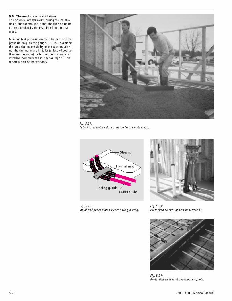
5 - 8 9.96 RFH Technical Manual
Fig. 5.21:Tube is pressurized during thermal mass installation.
Fig. 5.22:Install nail guard plates where nailing is likely.
Sleeving
Thermal mass
RAUPEX tubeNailing guards
5.5 Thermal mass installationThe potential always exists during the installa-tion of the thermal mass that the tube could becut or pinholed by the installer of the thermalmass.
Maintain test pressure on the tube and look forpressure drop on the gauge. REHAU considersthis step the responsibility of the tube installer,not the thermal mass installer (unless of coursethey are the same). After the thermal mass isinstalled, complete the inspection report. Thisreport is part of the warranty.
Fig. 5.23:Protection sleeves at slab penetrations.
Fig. 5.24:Protection sleeves at construction joints.

RFH Technical Manual 9.96 5 - 9
Fig. 5.25:The design will have specified how many turns each valve will require to balance each circuit.
5.6 Start-up, balance and close-outThermal masses composed of concrete materi-als shall be cured for 28 days prior to systemstart-up. Gypsum-based thermal masses havedifferent requirements. Consult the supplier toverify cure time.
Starting up the heat source and then distribut-ing hot water to each zone and subsequentlyeach circuit brings the entire floor heatingsystem on-line. It is best to warm the thermalmass up slowly during start-up to help preventpossible shock to the slab. Warm-up periodscould take as many as 10 days.
Once the system is on-line, all the balancingvalves are to be adjusted as directed by thedesign plan.
It is always best to set the balancing valvesfrom data derived from engineering tables.Finding the correct balance by trial and error isvery difficult.
Provide the building owner or maintenance staffwith training on their radiant floor heating sys-tem to minimize callbacks. Complete the RFHSystems "Project Start-up & Site InspectionReport" form and the warranty.
REHAU provides a label to be mounted at eachmanifold location and electrical circuit box asnotification that floor heating tube is installed.
Fig. 5.26:Mount this notice where it will be seen.
THIS FLOOR CONTAINS PRESSURIZED WATER TUBES.CONTACT BUILDING OWNER'S REPRESENTATIVE PRIOR TO
PENETRATION OF FLOOR.
REHAU UNDERFLOORHEATING TUBE INSTALLED
CAUTION!

REHAU IncorporatedNorth American Headquarters & Technical CenterP. O. Box 1706Leesburg, Virginia 20177Toll Free FAX 1-800-627-3428Phone: 703-777-5255FAX: 703-777-3053
Sales OfficesUnited States Northeast: P.O. Box 297, Waldwick, New Jersey 07463 • (201) 447-1190
Southeast: 2606-204 Phoenix Drive, Greensboro, North Carolina 27406 • (910) 852-2023Midwest: 129 Joey Drive, Elk Grove Village, Illinois 60007 • (847) 364-58505075 Cascade Road, S.E., Suite J, Grand Rapids, Michigan 49505 • (616) 285-68677101 Northland Circle, Brooklyn Park, Minnesota 55428 • (612) 535-2148West: 1501 Railroad Street, Corona, California 91720 • (909) 549-9017
Canada Newfoundland: 5 Kyle Avenue, Mt. Pearl, Newfoundland A1N 4R4 • (709) 747-3909Maritimes: R.R. #2 Murray Road, Port Elgin, New Brunswick E0A 2K0 • (506) 538-2346Québec: 625 Lee Avenue, Baie d'Urfé, Québec H9X 3S3 • (514) 457-3345Ontario: 1149 Pioneer Road, Burlington, Ontario L7M 1K5 • (905) 335-3284Praries: 11 Plymouth Street, Unit 100, Winnipeg, Manitoba R2X 2V5 • (204) 697-2028Western Canada: P.O. Box 688, Abbotsford, British Columbia V2S 6R7 • (604) 852-4527
ISO 9001
ICBO ES ER–5200
Printed in USA 855.601 9.96© Copyright by REHAU Incorporated, 1995. All rights reserved.
The information contained herein is believed to be reliable, but no representation, guarantees, or warranties of any kind are made as to its accuracy, suitability for particular applications, or theresults to be attained therefrom. Before using, the user will determine suitability of the information for users intended use and shall assume all risk and liability in connection therewith. REHAUDISCLAIMS ALL WARRANTIES, EXPRESS OR IMPLIED, INCLUDING BUT NOT LIMITED TO ANY IMPLIED WARRANTIES OR MERCHANTABILITY OR OF FITNESS FOR A PARTICULARPURPOSE.