rehabilitation of a two lane covered bridge · rehabilitation of a two ... • allowable stress...
TRANSCRIPT

Rehabilitation of a Two‐Lane Covered Bridge
dPresented to:Second National Covered Bridge Conference
June 6, 2013
Presented by:
Sean T. James, P.E. – Project Manager([email protected])
Josif Bicja, P.E. – Project Engineer([email protected])
Manchester, NH USA

Presentation Outline• Background
• Bridge Description
• Project Purpose and Need• Structural Analysis Geometric Limitations / Load Cases/ Live Load Selection Geometric Limitations / Load Cases/ Live Load Selection Computer Model Arch Interaction Observations & Results Proposed Modifications
R h bilit ti P j t• Rehabilitation Project

BackgroundProject Location

Background• 5 Remaining Double Barrel Covered Bridges Roberts Covered Bridge, Eaton OH, 1829, 79’ Long Single Span,
Multiple Kingpost w/Arches, Pedestrian Only.Multiple Kingpost w/Arches, Pedestrian Only.
Ramp Creek Covered Bridge, Nashville IN, 1838, 96’ Long Single Span, Multiple Kingpost w/Arches, Vehicular.
h l d d h l ’ Philippi Covered Bridge, Philippi WV, 1852, 286’ Long Four Span, Long Truss, Vehicular.
Shelburne Museum Covered Bridge, Shelburne VT, 1845, 168’ Long Single Span, Multiple Kingpost w/Arches, Pedestrian Only.
Pulp Mill Covered Bridge, Middlebury/Weybridge VT, 1853, 200’ Long Three Span Multiple Kingpost w/Arches VehicularLong Three Span, Multiple Kingpost w/Arches, Vehicular.

BackgroundP l Mill C d B id• Pulp Mill Covered Bridge
• Frequently Cited Built From 1805 and 1820• VTrans Record B ilt in 1853• VTrans Record Built in 1853• National Register of Historic Places in Sept. 10, 1974• AADT Volume of 1 900 Vehicles• AADT Volume of 1,900 Vehicles• Originally Built as 180’ Single Clear Span, Extensive Sagging• Nail Laminated Wood Arches Added in 1859‐60• Nail Laminated Wood Arches Added in 1859‐60• Two Stone Masonry Piers with Timber Cribbing in Late 19thCenturyy

BackgroundM j R h bilit ti i 1979 80• Major Rehabilitation in 1979‐80 Stone Masonry Piers Encased in Concrete New Concrete Facing of Abutments and New BackwallsNew Concrete Facing of Abutments and New Backwalls Portions of Arches and Truss Bottom Chords Replaced New Steel Hanger Rods Added to Connect the Arches to the Bottom Chord at Each Panel Point
New 6” x 6” Pressure Treated Lower Lateral Braces Installed
• North Truss and Arch (West Span) Rehabilitated in 1991• North Truss and Arch (West Span) Rehabilitated in 1991• Interior Truss and Arch (East Span) Rehabilitated in 2002• A Pedestrian Bridge Constructed in Mid‐1990’s• A Pedestrian Bridge Constructed in Mid‐1990 s

Bridge Description200’ 3 S C ti Ott C k• 200’, 3 Span Continuous, over Otter Creek
• M. Kingpost Trusses w/Arches 3 Trusses 4 Arches 3 Trusses, 4 Arches
• 2 Lanes, 8’‐6” Wide Curb‐Curb, 26’ Out‐Out• 10’‐6” Vertical Clearance• 10 6 Vertical Clearance• 4 Tons Live Load Capacity Goal

Bridge DescriptionUpstream Elevation
Downstream Elevation
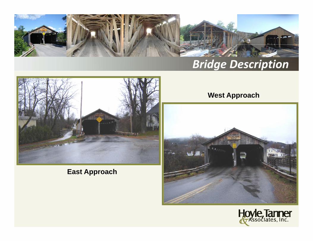
Bridge Description
West Approach
East Approach

Bridge Description
Roof Framing

Bridge Description
Upstream Barrel Downstream BarrelUpstream Barrel Downstream Barrel

Bridge Description
Bridge East Pier & Floor Framing

Project Purpose and NeedB id i P C diti• Bridge in Poor Condition Broken, Rotted, Impact Damaged Members Truss Vertical Member Issues Truss Vertical Member Issues Previous Repairs Sag in Truss Spans Snap Through Buckling of Arches
• Preserve Historic Covered Bridge• Critical Link Between Towns

Project Purpose and Need
Member Split Member Split
Member Impact Damage

Project Purpose and Need
Rot
Break Break
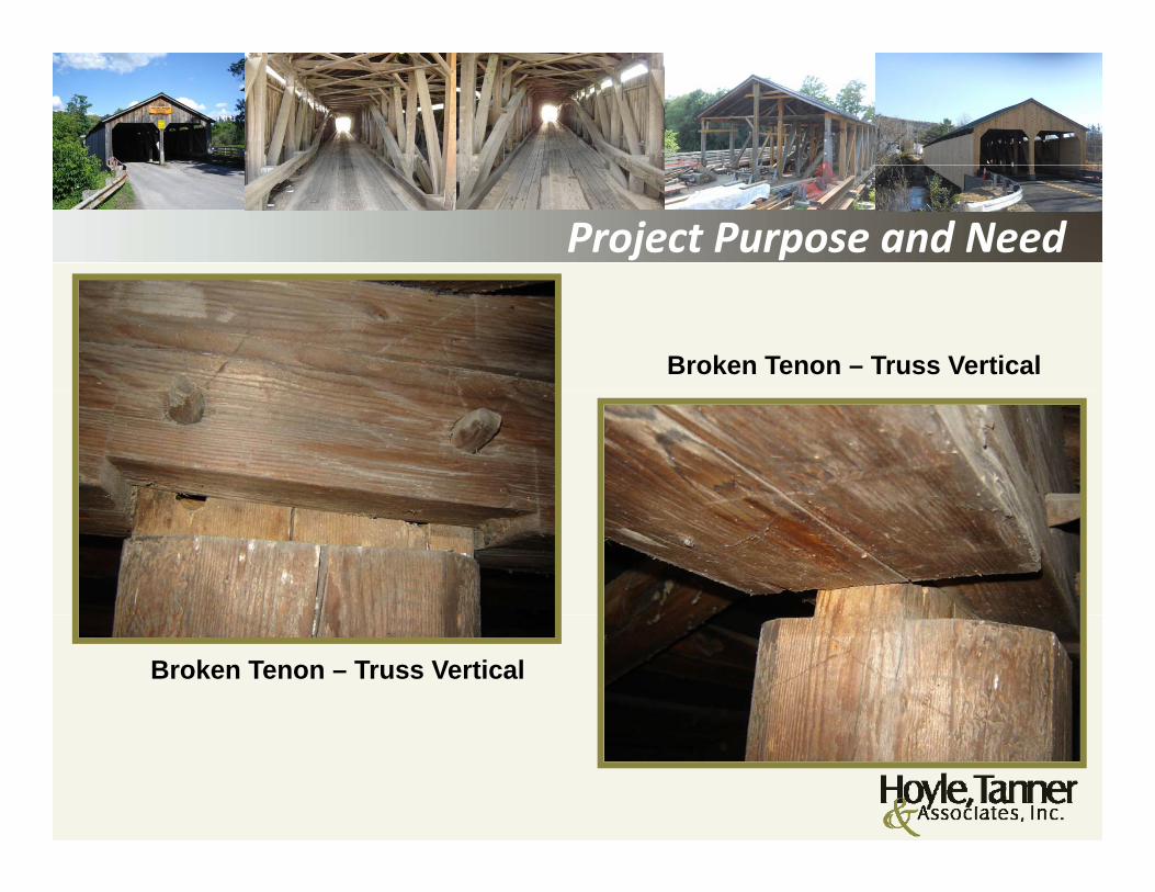
Project Purpose and Need
Broken Tenon – Truss Vertical
Broken Tenon – Truss Vertical
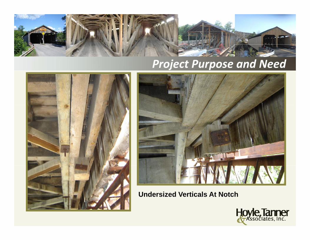
Project Purpose and Need
Undersized Verticals At NotchUndersized Verticals At Notch
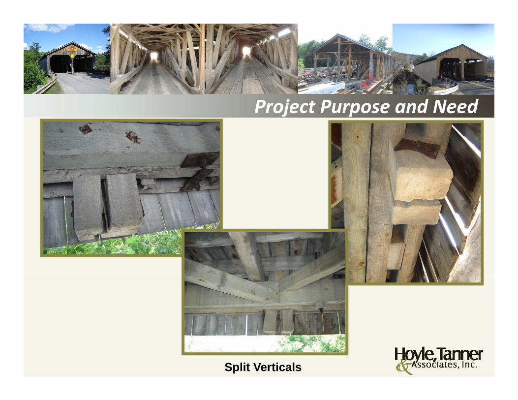
Project Purpose and Need
Split Verticals

Project Purpose and Need
Previous Repairs
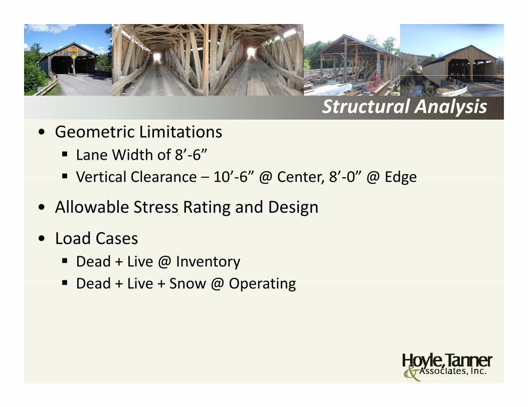
Structural Analysis G t i Li it ti• Geometric Limitations Lane Width of 8’‐6” Vertical Clearance – 10’‐6” @ Center 8’‐0” @ Edge Vertical Clearance 10 ‐6 @ Center, 8 ‐0 @ Edge
• Allowable Stress Rating and Design
• Load Cases Dead + Live @ Inventory Dead + Li e + Sno @ Operating Dead + Live + Snow @ Operating

Structural Analysis Li L d• Live Load Lane Load Evaluated H4 (4 Tons) H4 (4 Tons)
Truck Train
5 Load Cases, Both Lanes Loaded5 Load Cases, Both Lanes Loaded
3D Computer Model

Structural Analysis H4 L d CH4 Load Cases
Three-Dimensional Computer Simulation of the Pulp Mill Covered Bridge - Unloaded

Structural Analysis
Arch Interaction / Condition

Structural Analysis Ob ti & R lt• Observations & Results
Poor Connection Capacity of Vertical to Chord
3 Span Configuration Results in Member Stress Reversals
Load Sharing of Trusses and Arches Critical Relative Stiffness Determined to Share Load
Limited by Bolted Connection
Live Load Stresses Approx. 30‐40% of Dead Load Stresses
Most Members Controlled by Multiple Truck Load Case

Structural Analysis
Proposed Modifications to the Interior Truss
Legend:5”x5” Timber½” Steel RodSolid Blocking

Rehabilitation Project• Three Ends of Arches Rebuilt• Several Truss Member Replaced or Repaired due to Strength & ConditionStrength & Condition
• All Arch Hanger Rods Removed• Connections of Arches to Verticals Strengthened Co ect o s o c es to e t ca s St e gt e ed• Bottom Chord Replaced• Reversible Modification to Interior Truss• Several Roof Rafters Replaced In‐Kind or Sistered

Rehabilitation Project• New Upper Lateral Bracing Installed• Several Knee Braces and Cross Beams Replaced In‐Kind• All Stringers Removed• All Stringers Removed• Several Floor Beams Replaced In‐Kind• Existing Decking Replacedst g ec g ep aced• Limited New Lateral Bracing Installed• New Wood Curb Installed

Rehabilitation ProjectT d A h R li d• Trusses and Arches Realigned
• Protectowire and Lighting Installed• Fire Retardant/Insecticide Coatings Applied• Fire Retardant/Insecticide Coatings Applied• Minor Approach Work• Minor Repairs to Existing Substructure• Minor Repairs to Existing Substructure• Total Construction Cost $1.7 Million
Rehabilitation Project
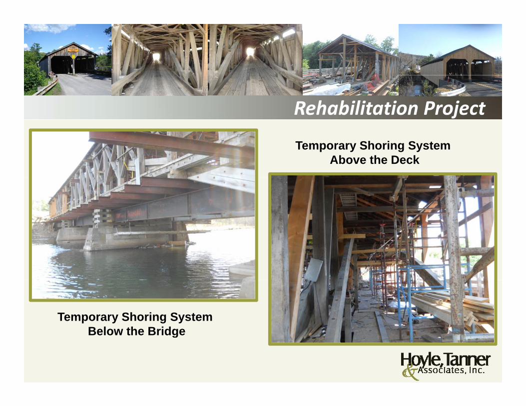
Temporary Shoring System Above the Deck
Temporary Shoring System Below the BridgeBelow the Bridge

Rehabilitation Project
New Bottom Chord
New Truss Verticals

Rehabilitation Project
Sistered Roof Rafters
Rebuilt East End of North Arch

Rehabilitation Project
Fire Detection Wires Underside of Bridge
Typical Floor Framing at Arch Locations

Rehabilitation Project
Ribbon Cutting CeremonyNovember 9, 2012
1St Car to Cross the Bridge November 9, 2012November 9, 2012

Rehabilitation Project
Question & Answer
S T J P E ( j @h l t )Sean T. James, P.E. ([email protected])
Josif Bicja P E (jbicja@hoyletanner com)Josif Bicja, P.E. ([email protected])
150 Dow StreetManchester, NH 03101