regulatory guide 1.132, site investigations for ...special or unusual problems such as swelling...
TRANSCRIPT

U.S. NUCLEAR REGULATORY COMMISSION September 1977
0-0
)REGULATORY GUIDE* OFFICE OF STANDARDS DEVELOPMENT
REGULATORY GUIDE 1.132
SITE INVESTIGATIONS FOR FOUNDATIONSOF NUCLEAR POWER PLANTS
A. INTRODUCTION programs as well as specific guidance for conductingAppendix A, "Seismic and Geologic Siting Criteria subsurface investigations, the spacing and depth of
for Nuclear Po%%er Plants." to 10 CFR Part 100, borings, and sampling. Appendix A provides defini-"'Reactor Site Criteria," establishes requirements for lions for some of the terms used in this guide. Theseconducting site investigations to permit an evaluation terms are identified in the text by anasterisk. Appen-
of the site and to provide information needed for dix B tabulates methods of conducting subsurface in-
seismic response analyses and engineering design. Re- vestigations. and Appendix C gives cfiteria for the
quirements include the development of geologic in- spacing and depth of borings.for.safety-related struc-lures in regions of favorable or-uniform conditions.formation relevant to the stratigraphy. lithology. eeecsLtdih.tx n
geologic history, and structural geology of the site References cited in'.he text and appendices are listed
and the evaluation of the engineering properties of in Appendix D.., Appendix E contains a
subsurface materials, bibliogr.aphical.liting oLreated material.
Safety-related site characteristics are identified in . DISCUSSIONdetail in Rcgulatory Guide 1.70. "Standard For- l.,Cenera.,mat and Content of Safety Analysis Reports for Sii'6i'inve.itigations for nuclear power plants are
* Nuclear Power Plants." Regulatory' Guide 4.7. e .*sne sar• to determine the geotechnical charac-"General Site Suitability Criteria for Nuclear Poyer ,;eristics of a site that affect the design, performance,Stations," discusses major site characteristics thi'a- ,and afety of plants. The investigations produce thefeet site suitabilitv. .... . information needed to define the overall site geology
This guide describes programs of sitiinv stihtions that is necessary for an understanding of subsurfacethat would normally meet the needifor evalua[ing conditions and for identifying potential geologic andthe safety of the site from the standpý'int of•hfe per- earthquake hazards that may exist at the site.formance of foundations and earthwor'46&er most Investigations for hazards such as faulting.anticipated loading conditions, including earth- landslides, cavernous rocks, ground subsidence, andquakes. It also describe.6 ite investigations required soil liquefaction are especially important.to evaluate geotec hlical,•laramcters needed, forengineering anffy1.i$ Ma, deslgn. The site investiga- Site investigations also provide information neededtions discus ind in•Us Nide are applicable to both to define local foundation and groundwater condi-
S' t ions as well as the geotechnical parameters neededland uandi.cfflo~re si;. This guide does not deal with tosa
hydr Ai.i lions, except for groundwater for engineering analysis and design of foundationsicasu _"Its, nor does . it discuss geophysical and earthworks. Geotechnical parameters needed for
• iethodlM subsurface exploration. analysis and design include, but are not limited to.IV those used to evaluate the bearing capacity o' foun-
This guide provides general guidance and recom- dation materials, lateral earth pressures against walls.mend'ations for developing site-specific investigation the stability of cuts and slopes in soil and rock. the ef-
USNRC REGULATORY GUIDES CooIMo-iit Q106111i I. -. 'It ft, If-. -I.,''tv 1i .11.- C. .tn'-'s, Uj ýj N-iI'. "It -I,
Reu ir Guw. wei. mun' lia'leIi ufewnix 'b i natlke t'.ivlalbli! to tht! public methods Leloitv C ......'....... r) ..V.Ni-troi'v,. 1) C. 20 f;, At iiiio I ttajInlS*t'tCC elitalie. to to.' NRC %iff,
1 Pl'ti~~i'ie iit stCic Vliti of the Cows, v~ains
equlatt~oiri. to d.,fnieasi teh". ht t ta''tLv t h. ital ,n t'.ahl.z~tnq soccii~c~l problenti Th,-uil, %. ,, ...it th-' 10 1i~,i~ twi. li.'.wl iuasIt suisi 111l1itIs ,Cuftt-l%. Of i ittIa i giltiaI.nC" let J1tltiiCrinht. Rgu~ljustv u-df-
Mýuhiidt tanl :, UI'~l0 T 1,d ifll'fnt I isis thin"tl " UIou in lbme qoalIM wall be- accetil 7. fl eit rh .i-iI "a7faaca 7. T PI ,l'ViiWe..t InS.iftle it fthoy lriaval! J1 ( eAr for the,5 fiuolfut rtlluitii. lit Ifil, isisin.tce of conl~nasince 3 V rash tnil Mm. wmi Trtalcia- ftOcatalort filitfa
of at wirt sil r licesne lv vhe Comnnswn'ii. 'I 1 nsinr.stfa' SaIml i9 tt atl.s'u
Cjfmminti ind %uiiio loiii t'th'."to t1O! .- ia'"A'a.i
CinmtflS nl uprw n..1 [ ni Ini~ivsi.n c in... i-1,' tMuth ii.j I.'.I 'u, W -111W.11111t Wta e. inlQi fo,"'.~
11 Iiteat'l .15 .s iftiia -ia .tim -f .c iinillit. Clthitafs tOO1 n .t 1, ...... s I. rat, I~ s . %,ai q Ilt iwt ni-r 0ie I.ta'csu 'l t i ia
tcim.','fl i hin't ifliiiiiii w t'i ivitth al'-t'r C liva~ aniit Its wifes to-i'ia ,,*I~u~~ ,"nm liiiiis .tI4" h . th inthiutm nl I" t ,,,i 'U Si.aoi' htt.t'a"S i sn a.
t .' et vthai ft- ru ,ili.ni hs tit ...... a'S'Saa1amr.' U -ill Ii" ()it ... ........a.gstas JlijllIi ii.a, iis'rtaI i;iI'US:a .a...;aifa *Caa',a -

fect of earthquake-induced motions through underly-ing deposits on the response of soils and structures(including the potential for inducing liquefaction insoils). and those needed to estimate the expected set-tement of structures. Geotechnical parameters arcalso needed for analysis and design of plant area fills,structural fills, backfills. and earth and rockfill dams.dikes, and other water retention or flood protectionstructures.
Site information needed to assess the functional in.tegrity of foundations with respect to geologic andgeotechnical considerations include:
a. The geologic origin, types, thicknesses. se.quence. depth. location, and areal extent of soil antrock strata and the degree and extent of theiiweathering:
h. Orientation and characteristics of foliationsbedding. jointing, a !d faulting in rock,
c. Groundwater c,,nditions:
d. The static and dynamic engineering properties of subsurface materials:
e. Information regarding the results of investigations of' adverse geological conditions such a,cavities, joints, faults. fissures. or unfavorable soiconditions:
f. Information related to man's activities such awithdrawal of fluids from or addition of fluids to thsubsurface, extraction of minerals, or loading effectof dams or reservoirs: and
g. Information detailing any other geologic condition discovered at the site that may affect the desigor performance of the plant or the location of structures.
2. Reconnaissance Investigations and LiteraturReviews
Planning of subsurface investigations and the iiterpretation of data require thorough understandirof the general geology of the site. This can be olrained by a reveiw. either preceding or accompanyirthe subsurface investigation, of available documeitary materials and results of previous investigationIn most cases, a preliminary study of the site geololcan be done by review of existing current anhistorical documentary materials and by studyaerial photographs and other remote sensirimagery. Possible sources of current and historicdocumentary information may include:
a. Geology and engineering departmentsState and loce! universities,
b. State government agencies such as the State,* Geological Survey,
c. U.S. Government agencies such as the U.S.Geological Survey and the U.S. Army Corps ofEngineers.
d. Topographic maps.
e. Geologic and geophysical maps,
" f. Engineering geologic maps.
g. Soil survey maps.
" Ih. Geologic reports and other geologicalliterature,
i. Geotechnical reports and other geotechnical
literature.
j. Well records and water supply reports.
k. Oil well records.
I. Hydrologic maps.
m. Hydrologic and tidal data and flood records,
s n. Climate and rainfall records.
o. Mining history, old mine plans. and sub-sidence records.
C p. Seismic data and historical earthquakes records.
q. Newspaper records of landslides, floods.- earthquakes. subsidence, and other events oflgeologicn or geotechnical significance,
r. Records of performance of other structures inthe vicinity, and
es. Personal communication with local inhabi-
tants and local professionals.
Special or unusual problems such as swelling soilsIg and shales (subject to large volume changes with
b- changes in moisture), occurrences of gas, cavities inIg soluble rocks, subsidence caused by mining or pump-I- ing ofwater. gas. or oil from wells, and possible uplifts. due to pressurization from pumping of water, gas, ord oil into the subsurface may require consultation with)d individuals, institutions, or firms having experience
of in the area with such problems.
al The site investigation includes detailed surface ex-
ploration of the immediate site area and adjacent en-virons. Further detailed surface exploration also may
of be required in areas remote to the immediate plantsite to complete the geologic evaluation of the site or
1.132-2
0I
a.-- M

to conduct detailed investigations of surface faultingor other features. Surface exploration needed for theassessment of the site geology is site dependent andmay be carried out with the use of any appropriatecombination of geological, geophysical (seismicrefraction), or engineering techniques. Normally thisincludes the following:
a. Detailed mapping of topographic,hydrologic, and surface geologic features, as ap-propriate for the particular site conditions, withscales and contour intervals suitable for analysis andengineering design. For offshore sites, coastal sites,or sites located near lakes or rivers this includestopography and detailed hydrographi, surveys to theextent that they are needed for site evaluation andengineering design.
b. Detailed geologic interpretations of aerialphotographs and other remote-sensing imagery, asappropriate for the particular site conditions, to as-sist in identifying rock outcrops, soil conditions,evidence of past landslides or soil liquefaction, faults,fracture traces, and lineaments.
c. Detailed onsite mapping of local engineeringgeology and soils.
d. Mapping of surface water features such asrivers, streams, or lakes and local surface drainagechannels, ponds, springs, and sinks at the site.
3. Groundwater Investigations
Knowledge of groundwater conditions. theirrelationship to surface waters, and variations as-sociated with seasons or tides is needed for founda-tion analyses. Groundwater conditions should beobserved in borings at the time they are made:however, for engineering applications, such datamust be supplemented by groundwater observationsmade by means of properly installed wells orpiezometers* that are read at regular intervals fromthe time of their installation at least through the con-struction period. The U.S. Army Corps of Engineers'manual on groundwater and pore pressure observa-tions in embuinkment dams and their foundations(Ref. I) provides guidance on acceptable mrthods forthe installation and maintenance of piezometer andobservation well* instrumentation. Piezometer orwell installations should be made in as many loca-tions as needed to define groundwater conditions.When the possibility of perched groundwater tablesor artesian pressures is indicated by borings or otherevidence, piezometer installation should be made tomeasure each piezometric level independently. Careshould be taken in the design and installation ofpiezometers to prevent hydraulic communication
between aquifers. The occurrence of artesian pressurein borings should be noted on boring logs. and theirheads should be measured and logged.
Where construction dewatering is required,piezometers or observation wells should be used dur-ing construction to monitor the groundwater surfaceand pore pressures beneath the excavation and in theadjacent ground. The guide does not covergroundwater monitoring needed during constructionin plants that have permanent dewatering systems in-corporated in their design.
4. Subsurface Investigations
a. General
The appropriate depth, layout, spacing. and sampl-ing requirements for subsurface investigations aredictated by the foundation requirements and by thecomplexity of the subsurface conditions. Methods ofconducting subsurface investigations are tabulated inAppendix B, and criteria for the spacing and depth ofborings for safety-related structures, where favorableor uniform geologic conditions exist. are given in Ap-pendix C.
Subsurface explorations for less critical founda-tions of power plants should be carried out with spac-ing and depth of penetration as necessary to definethe general geologic and foundation conditions of thesite. Subsurface investigations in areas remote fromplant foundations may be needed to complete thegeologic description of the site and confirm geologicand foundation conditions and should also becarefully planned.
Subsurface conditions may be consideredfavorable or uniform if the geologic and stratigraphicfeatures to be defined can be correlated from one bor-ing or sounding* location to the next with relativelysmooth variations in thicknesses or properties of thegeologic units. An occasional anomaly or a limitednumber of unexpected lateral variations may occur.Uniform conditions permit the maximum spacing ofborings for adequate definition of the subsurface con-ditions at the site.
Occasionally soil or rock deposits may be en-countered in which the deposition patterns are socomplex that only the major stratigraphic boundariesare correlatable, and material types or properties mayvary within major geologic units in an apparentlyrandom manner from one boring to another. Thenumber and distribution of borings needed for theseconditions will exceed those indicated in Appendix Cand are determined by the degree of resolutionneeded in the definition of foundation properties.
1.132-3

The cumulative thicknesses of the various materialtypes, their degree of variability, and ranges of thematerial properties must be defined.
If there is evidence suggesting the presence of localadverse anomalies or discontinuities such as cavities.sinkholes, fissures, faults, brecciation. and lenses orpockets of unsuitable material, supplementary bor-ings or soundings at a spacing small enough to detectand delineate these features are needed. It is impor-tant that these borings should penetrate all suspectzones or extend to depths below which their presencewould not influence the safety of the structures.Geophysical investigations may be used to supple-ment the boring and sounding program.
in planning the exploration program for a site,consideration should also be given to the possibilitythat the locations of structures may be changed, andthat such changes may require additional explorationto adequately define subsurface conditions at thefinal locations.
The location and spacing of borings, soundings.and exploratory excavations should be chosencarefully to adequately define subsurface conditions.A uniform grid may not provide the most effectivedistribution of exploration locations unless the siteconditions are very uniform. The location of initialborings should be determined on the basis of condi-tions indicated by preliminary investigations. Loca-tions for subsequent or supplemental explorationsshould be chosen in a manner so as to result in thebest definition of the foundation conditions on thebasis of conclusions derived from earlier exploratorywork.
Whereve feasible, the locations of subsurface ex-plorations should be chosen to permit the construc-tion of geological cross sections in important subsur-face views of the site.
It is essential to verify during construction that insitu conditions have been realistically estimated dur-ing analysis and design. Excavations made duringconstruction provide opportunities for obtaining ad-ditional geologic and geotechnical data. All construc-tion excavations for safety-related structures andother excavations important to the verification ofsubsurface conditions should be geologically mappedand logged in detail. Particular attention should begiven to the identification of thin strata or othergeologic features that may be important to founda-tion behavior but. because of their limited extent,were previously undetected in the investigationsprogram. If subsurface conditions substantially differfrom those anticipated, casting doubt on the ade-quacy of the design or expected performance of thefoundation. there may be a need for additional ex-ploration and redesign.
b. lnvestigations Related to SpeciflC Site Conditions
Investigations for specific site conditions should in-clude the following:
(I) Rock. The engineering characteristics ofrocks are related primarily to their structure. bed-ding. jointing, fracturing, weathering, and physicalproperties. Core samples are needed to observe anddefine these features. Suitable coring methods shouldbe employed in sampling, and rocks should besampled to a depth below which rock characteristicsdo not influence foundation performance. Deeperborings'mav be needed to investigate zones critical tothe evaluation of the site geology. Within the depthintervals influencing foundation performance. zonesof poor core recovery, low RQD (Rock QualityDesignation).* dropping of rods. lost drilling fluidcirculation. zones requiring casing. and other zoneswhere drilling difficulties are encountered should beinvestigated by means of suitable logging or in situobservation methods to determine the nature.geometry. and spacing of any discontinuities oranomolous zones. %%'here soil-filled voids, channels,or fissures are encountered. representative samples*of the filling materials are needed. Where there isevidence of significant residual stresses, they shouldbe evaluated on the basis of in situ stress or strainmeasurements.
(2) Granular Soils. Investigations of granularsoils should include borings with splitspoon samplingand Standard Penetration Tests with sufficientcoverage to define the soil profile and variations ofsoil conditions. Soundings with cone penetrationtests may also be used to provide useful supplementaldata if the device is properly calibrated to site condi-tions.
Suitable samples should be obtained for soil iden-tification and classification, in situ density determina-tions. mechanical analyses, and anticipatedlaboratory testing. In these investigations, it is impor-tant to obtain the best possible undistrbed samples*for testing to determine whether the sands are suf-ficiently dense to preclude liquefaction or damagingcyclic deformation. The number and distribution ofsamples will depend on testing requirements and thevariability of the soil conditions. In general, however,samples should be included from at least one prin-cipal boring* at the location of each Category I struc-ture. Samples should be obtained at regular intervalsin depth and when changes in materials occur.Criteria for the distribution of samples are given inregulatory position 5.
Granular soils containing coarse gravels andboulders are among the most difficult materials to
.132-4U

sample. Obtaining good quality samples in thesecoarser soils often requires the use of trenches, pits.or other accessible excavations* into the zones of in-terest. Also, extreme care is necessary in interpretingresults from $he Standard Penetration Test in thesematerials. Often such data are misleading and mayhave to be disregarded. When sampling of thesecoarse soils is difficult. informationthat may be lostwhen the soil is later classified in the lhboratoryshould be recorded in the field. This informationshould include observed estimates of percent cobbles,boulders, and coarse material and their hardness.shape, surface coating. and degree of weathering ofcoarse materials.
(3) Moderately v Compressible or Normally Con-solidated Clay' or Clay ve Soils. The properties of afine grained soil are related to its in situ structure.*and therefore the recovery and testing of good un-disturbed samples are necessary. Criteria for the dis-tribution and methods for obtaining undisturbedsamples are discussed in regulatory position 5.
(4) Stibsurjaice Cavilies. Subsurface cavities mayoccur in water-soluble rocks. lavas, or weakly in-durated sedimentary rocks as the result of subterra-nean solutioning and erosion. Because of the widedistribution of carbonate rocks in the United States.the occurrence of features such as cavities, sinkholes.and solution-widened joint openings is common. Forthis reason, it is best to thoroughly investigate anysite on carbonate rock for solution features to deter-mine their influence on the performance of founda-tions.
Investigations may be carried out with boringsalone or in conjunction with accessible excavations,soundings, pumping tests, pressure tests, geophysicalsurveys, or a combination of such methods. The in-vestigation program will depend on the details of thesite geology and the foundation design.
Indications of the presence of cavities, such aszones of lost drilling fluid circulation, water flo\%inginto or out of drillholes, mud fillings, poor corerecovery, dropping or settling of drilling rods.anomalies in geophysical surveys, or in situ tests thatsuggest voids, should be followed up with moredetailed investigations. These investigations shouldinclude excavation to expose solution features or ad-ditional borings that trace out such features.
The occurrence, distribution, and geometry of sub-surface cavities are highly unpredictable, and nopreconstruction exploration program can ensure thatall significant subsurface voids will be fully revealed.Experience has shown that solution features may re-main undetected even where the area has been in-vestigated by a large number of borings. Therefore,where a site is on solution-susceptible rock, it may
sometimes be necessary to inspect the rock after strip-ping or excavation is complete and the rock is ex-posed. Remedial grouting or other correctivemeasures should be employed where necessary.
(5) Materials Lb.suitahhle Jbr Fotmdatitnhs. Bor-ings and representative sampling and testing shouldbe completed to delineate the boundaries of un-suitable materials, These boundaries should be usedto define the required excavation limits.
(6) Borrow Materials. Exploration of borrowsources requires the determination of the locationand amount of borrow fill materials available.Investigations in the borrow areas should be of suf-ficient hori.,;mal and vertical intervals small enoughto determine the material variability and should in-clude adequate sampling of representative materialsfor laboratory testing.
c. Sam...nt
All soil and rock samples obtained for testingshould be representative. In many cases, to establishphysical properties it is netcssary to obtain un-disturbed samples that preserve the in situ structureof the soil. The recovery of undisturbed samples isdiscussed in Section B.6 of this guide.
Sampling of soils should include. as a minimum.recovery of samples for all principal borings atregular intervals and at changes in strata. A numberof samples sufficient to permit laboratory determina-tion of average material properties and to indicatetheir variability is necessary. Alternating splitspoonand undi!;Iurbed samples with depth is recom-mended. Where sampling is not continuous, theelevations at which samples are taken should be stag-gered from boring to boring so as to provide con-tinuous coverage of samples within the soil column.In supplementary borings,* sampling may be con-fined to the zone of specific interest.
Relatively thin zones of weak or unstable soils maybe contained within more competent materials andmay affect the engincering properties of the soil orrock. Continuous sampling in subsequent borings isneeded through these suspect zones. Where it is notpossible to obtain continuous samples in a single bor-ing. samples may be obtained from adjacent closelyspaced borings in the immediate vicinity and may beused as representative of the material in the omitteddepth intervals. Such a set of borings should be con-sidered equivalent to one principal boring.
d. Determining the Engineering Properties of Sub-surface Materials
The shear strengths of foundation materials in allzones subjected to significant imposed stresses must0
1.132-5

- - I
be determined to establish whether they are adequateto support the imposed loads with an appropriatemargin of safety. Similarly, it is necessary both todetermine the compressibilities and swelling poten-tials of all materials in zones subjected to significantchanges of compressive stresses and to establish thatthe deformations will be acceptable. In some casesthese determinations may be made by suitable in situtests and classification tests. Other situations may re-quire the laboratory testing of undisturbed samples.Determination of dynamic modulus and dampingvalues for soil strata is required 'or earthquakeresponse analyses. These determinations may bemade by laboratory testing of suitable undisturbedsamples in conjunction with appropriate in situ tests.
5. Methods and Procedures for ExpLuratory Drilling
In nearly ever%, site investigation, the primarymeans Of subsurface exploration are borings andborehole sampling. Drilling methods and proceduresshould be compatible with sampling requirementsand the methods of sample recovery.
The top of the hole should be protected by asuitable surface casing where needed. Below groundsurface, the borehole should be protected by drillingmud or casing. as necessary, to prevent caving anddisturbance of materials to be sampled. The use ofdrilling mud is preferred to prevent disturbance whenobtaining undisturbed samples of granular soils.However, casing may be used if proper steps aretaken to prevent disturbance of the soil beingsampled and to prevent upward movement of soilinto the casing, Washing with open-ended pipe forcleaning or advancing sample borcholes should notbe permitted. Bottom-discharge bits should be usedonly with low-to-medium fluid pressure and withupward-deflected jets.
The groundwater or drilling mud level should bemeasured at the -start and end of each work day forborings in progress, at the completion of drilling, andat least 24 hours after drilling is completed, In addi-tion to pertinent information normally recorded, alldepths and amounts of water or drilling mud losses,together with depths at which circulation isrecovered, should be recorded and reported on bor-ing logs and on geological cross sections. Logs andsections should also reflect incidents of settling ordropping of drill rods, abnormally low resistance todrilling or advance of samplers, core losses, in-stability or heave of the side and bottom ofborcholes, influx of groundwater, and any otherspecial feature or occurrence. Details of informationthat should be presented on logs of subsurface in-vestigations are given in regulatory position 2.
Depths should be measured to the nearest tenth ofa foot and be correlatable to the elevation datumused for the site. Elevations of points in the borehole
should also be determined with an accuracy of ±0. Ift. Deviation surveys should be run in all boreholesthat are used for crosshole seismic tests and in allboreholes where deviations are significant to the useof data obtained. After use, it is advisable to grouteach borehole with cement to prevent vertical move-ment of groundwater in the borehole.
6. Recovery of Undisturbed Soil Samples
The best undisturbed samples are often obtainedby carefully performed hand trimming of block sam-pies in accessible excavations. However, it is normal-ly not practical to obtain enough block samples at therequisite spacings and depths by this method alone. Itis customary, where possible, to use thin-wall tubesamplers in borings for the major part of the un-disturbed sampling. Criteria for obtaining un-disturbed tube samples are given in regulatory posi-tion 5.
The recovery of undisturbed samples of goodquality is dependent on rigorous attention to detailsor equipment and procedures. Proper cleaning of thehole. by methods that do not produce avoidable dis-turbance of the soil, is necessary before sampling.The sampler should be advanced in a manner thatdoes not produce avoidable disturbance. For exam-ple, when using fixed-piston-type samplers. the drill-ing rig should be firmly anchored, or the pistonshould be fixed to an external anchor, to prevent itsmoving upward during the push of the sampling tube.Care should be taken to ensure that the sample is notdisturbed during its removal from the borehole or indisassembling the sampler. References 2 and 3provide descriptions of suitable proccedures for ob-taining undisturbed samples.
With the conscientious use of proper field tech-niques, undisturbed samples in normally con-solidated clays and silts can usually be recovered bymeans of fixed-piston-type thin-wall tube samplerswithout serious difficulty. Recovery of good un-disturbed samples in sands requires greater care thanin clays, but with proper care and attention to detail,they can also be obtained with fixed-piston-type thin-wall tube samplers in most sands that are free ofbouiders and gravel size particles. Appendix B lists anumber of sampling methods that are suitable for usein these and other materials.
Undisturbed samples of boulders, gravels, or sand-gravel mixtures generally are difficult to obtain, andoften it is necessary to use hand sampling methods intest pits, shafts, or other accessible excavations to getgood samples.
When obtaining undisturbed samples of granularsoils below the groundwater table, dewatering bymeans of well points or other suitable methods may
1.132-6

he required. Osterberg and Varaksin (Ref. 4) describea sampling program using dewatering of a shaft insand with a frozen surrounding annulus. Samplessuitable for density determination, though not fortests of mnichanical properties. may sometimes be ob-tained I'roi• boreholes with the help of chemicalstabilization or impregnation (Refs. 5. 6). Specialprcautions are required when toxic chemicals areused. Also. where aquifers are involved, it may not beadvisable to injeit chemicals or grouts into them.Useful discussions of methods of sampling granularsoils are given by l-vorslev (Ref. 7) and Barton(Rer. 8).
7. Handling. Field Storage, and Transporting of Sam-ples
Treatoiient of samples after their recovery from theground is as critica0l to their quality as the proceduresused in obtaining them. Samples of cohesionless soilsare particularly sensitive to disturbance in handlingand require extreme care during removal from theborehole, removal from the sampler. and subsequenthandling in order to prevent disturbance from impactand vibration (Ref. 2). Special precautions are re-quired in transporting undisturbed samples becauseof their sensitivity to vibration and impact. Theyshould be kept in a vertical position at all times.should be well padded to isolate them from vibrationand impacts. and should be transported with extremecare. Transportation by commercial carriers is notadvisable. Block samples should be handled bymethods that give them equivalent protection fromdisturbance. All undisturbed samples should beproperly sealed and protected against moisture loss.
Disturbed samples* may be sealed in the same wayas undisturbed samples. if in tubes. or may be placedin suitably marked, noncorroding. airtight con-tainers. Large representative samples may be placedin plastic bags, in tightly woven cloth, or in noncor-roding cans or other vessels that do not permit loss offine particles by sifting. Such samples may be trans-ported by any convenient means.
Rock cores need to be stored and transported indurable boxes provided with suitable dividers to pre-vent shifting of the cores in any direction. Theyshould be clearly labeled to identify the site, the bor-ing number, the core interval, and the top and hot-tom depths of the core. If the box has a removablelid, labeling should be placed on both the outside andinside of the box, as well as on the lid. Special con-tainers may be required to protect samples to be usedfor fluid content determinations and shale samples tobe used for tests of mechanical properties fromchanges in fluid content. Core samples should betransported with the care necessary to avoid breakageor disturbance.
C. REGULATORY POSITION
rhe site investigations program needed to deter-mine foundation conditions at a nuclear po%ker plantsite is highly dependent on actual site conditions. Theprogram should he flexible and adjusted as the site in-vestigation proceeds with the advice of experiencedpersonnel familiar with ti, site. The staff will revie\%the results of each site investigation program on acase-by-case basis and make an independent evaluv,-tion of foundation conditions in order to judge theadequacy of the information presented.
1. General Site Iniestigation
Site investigations for nuclear power plants Si.ouldbe adequaite. in terms of thoroughness. suit:•bility ofthe methods used. quality of execution o ' the work.and documentation. to permit an accurate determina-tion of the geologic and geotechnical conditions thataffect the design. performance, and safe(ty of theplant. The investigations should provide informationneeded to assess foundation conditions at the site ::ndto perform engineering analysis and design withreasonable assurance that foundation conditionshave been realistically estimated.
Information to be developed should, as ap-propriate. include (I) topographic. hydrologic.hydrographic, and geologic maps: (2) plot plans.showing locations of major structures and explora-tions: (3) boring logs and logs of trenches and excava-tions: and (4) geologic profiles showing excavationlimits for structures and geophysical data such astime-distance plots. profiles, and inhole surveys.Positions of all boreholes. piezometers. observationwells. soundings. trenches, exploration pits. andgeophysical investigations should be surveyed in bothplan and elevation and should be shown on plotplans. geologic sections, and maps. All surveysshould be related to a fixed datum. The above infor-mation should be in sufficient detail and be in-tegrated to develop an overall view of the project andthe geologic and geotechnical conditions affecting it.
2. Logs of Subsurface Imestigations
Boring logs should contain the date when the bor-ing was made. the location of the boring withreference to the coordinate system used for the site.the depths of borings, and the elevations with respect*to a permanent bench mark.
The logs should also include the elevations or thetop and bottom of borings and the level at which thewater table and the boundaries of soil or rock stratawere encountered, the classification and descriptionof the soil and rock layers, blow count values ob-tained from Standard Penetration Tests, percentrecovery of rock core, and Rock Quality Designation
1.132-7

I-
(RQD). Results of field permeability •tests andborehole logging should also be included on logs. Thetype of tools used in making the boring should berecorded. It' the tools were changed, the depth atwhich the change was made and the reason for thechange should be noted. Notes should be provided ofeverything significant to the interpretation of subsur-face conditions, such as lost drilling fluid, rod drops,and changes in drilling rate. Incomplete or aban-doned borings should be described with the same careas successfully completed borings. Logs of trenchesand exploratory excavations should be presented in aformat similar to the boring logs. The location of allexplorations should be shown on the geologic sectiontogether with elevations and important data.
3. Procedures for Subsurface lnvestigations
Some techniques widely used for subsurface in-vestigations are listed in Appendix B. It also cites ap-propriate standards and references procedures frompublished literaturelwith general guidelines on the ap-plicability, limitations, and potential pitfalls in theiruse. Additional suitable techniques are provided byother literature listed in Appendix D. The use or in-vestigations and sampling techniques other thanthose indicated in this guide is acceptable when it canbe shown that the alternative methods yield satisfac-tory results. The attainment of satisfactory results indriiling, sampling, and testing is dependent on thetechniques used, on care in details of operations, andon timely recognition of and correction of potentialsources of error. Field operations should be super-vised by experienced professional personnel at the
.site of operations, and systematic standards of prac-tice should be followed. Procedures and equipmentused to carry out the field operations should bedocumented, as should all conditions encountered inall phases of investigations. Experienced personnelthoroughly familiar with sampling and testingprocedures should also inspect and document sampl-ing results and transfer samples from the field tostorage or laboratory facilities.
4. Spacing and Depth of Subsurface Investigations
Criteria for the spacing and depth of subsurface ex-ploration at locations or safety-related structures forfavorable or uniform gcologic conditions are given inAppendix C. The application of these criteria is dis-cussed in Section B.4 of this guide, The investigativeeffort required for a nuclear power plant should begreatest at the locations of Category I structures andmay vary in intensity and scope in other areas ac-cording to their spatial and geolgical relations to thesite.
5. Sampling
Sampling of soils should include, as a minimum,the recovery of samples at regular intervals and at
changes in materials. Alternating splitspoon and un-disturbed samples with depth is recommended.
For granular soils, samples should be taken atdepth intervals no greater than 5 feet. Beyond a depthof 50 feet below foundation level, the depth intervalfor sampling may be increased to 10 feet. Also it isrecommended tital onw or more borings for each ma-jor structure be contiuously sampled. The borirgshould be reamed and cleaned between samples. Re-quirements fe" undisturbed sampling of granularsoils will depend on actual site conditions and re-quirements for laboratory testing. Some generalguidelines for recovering undisturbed samples aregiven in Section B.4.b(2) and Section B.6 of the dis-cussion of this guide. Experimentation with differentsampling techniques may be n,:cessary to determinethe method best suited to local soil conditions.
For compressible or normally consolidated clays.undisturbed samples should be continuousthroughout the compressible strata in one or moreprincipal borings for each major structure. Thesesamples should be obtained by means of suitablefixed-piston-type thin-wall tube samplers or bymethods that yield samples of equivalent quality.
Borings used for undisturbed sampling of soilsshould be at least 3 inches in diameter. Criteria forobtaining undisturbed tube samples include the fol-lowing:
a. Tubes should meet the specifications ofASTM Standard D 1587-67 (Ref. 9):
b. The Area Ratio* of the sampler should notexceed 13 percent and preferably should not exceed10 percent:
c. The Specific Recovery Ratio* should bebetween 90 and 100 percent: tubes with less recoverymay be acceptable if it appears that the sample mayhave just broken off and otherwise appears essential-ly undisturbed:
d. The Inside Clearance Ratio* should be theminimum required for complete sample recovery,
e. Samples recovered should contain no visibledistortion of strata or opening or softening ormaterials brought about by the sampling procedure.
6. Retention of Samples, Rock Core, and Records
Samples and rock cores from principal boringsshould be retained at least until the power plant islicensed to operate and all matters relating to the in-terpretation of subsurface conditions at the site havebeen resolved. The need to retain samples and corebeyond this time is a matter of judgment and should
6
1.132-8
II

b
0he evaluated on a case-by-case basis. Soil samples intubes will deteriorate with time and will not besuitable for any undisturbed testing. However, theymay be used as a visual record of what the foundationmaterial is like. Similarly, core or rock subject toslaking and rapid weathering such as shale will alsodeteriorate. It is recommended that photographs ofscil samples and rock core togedher with field andfinal logs of all borings and record samples withmaterial descriptions be preserved for a permanentrecord. Other important records of the subsurface in-vestigations program should also be preserved.
D. IMPLEMENTATIONThis guide will be used by the staff to evaluate the
results of site investigations, including the adequacyand quality of data provided to define foundationconditions and the geotechnical parameters neededfor engineering analysis and design. submitted in con-nection with construction permit applicationsdocketed after June 1. 1978. The staff will also usethis guide to evaluate the results of any new site in-vestigations performed after June 1, 1978. by aperson whose construction permit was issued on orbefore June 1. 1978.
1.132-9

APPENDIX A
DEFINITIONS
For the convenience of the user, the followingterms are presented with their definitions as used inthis guide:
Accessible exca'ation-an excavation made for thepurpose of investigating and sampling materials orconditions below the ground surface, of such shapeand dimensions as to permit the entry of personnelfor direct examination, testing, or sampling.
Area Ratio- (Ca) of a sampling device is definedas:
D: -13a De
where Do is the outside diameter of that part of thesampling device that is forced into the soil, and De isthe inside diameter, normally the diameter of the cut-ting edge.
Boring-ian exploratory hole in soil or rock, orboth, made by removal of materials in the form ofsamples or cuttings (cf. soundings).
Disturbed sample-a sarpple whose internal struc-ture has been altered to such a degree that it does notreasonably approximate that of the material in situ.Such a sample may be completely remolded, or itmay bear a resemblance to an undisturbed sample inhaving preserved the gross shape given it by a sampl-ing device.
Geoteclmical-of or pertaining to the earth sciences(geology, soils, seismology, and groundwaterhydrology) and that part of civil engineering whichdeals with the interrelationship between the geologicenvironment and the works of man.
In situ test-a test performed on in-place soil orrock for the purpose of determining some physicalproperty. As used in this guide, it includesgeophysical measurements.
Inside Clearance Ratio (Ci) of a sampling device isdefined as:
Di - Dei De
where Di is the inside diameter of the sample tube orliner and D. is the diameter .of the cutting edge.
Observation well-an open boring that permitsmeasuring the level or elevation of the groundwatertable.
Piezoineter-a device or instrument for measuringpore pressure or hydraulic potential at a level orpoint below the ground surface.
Principal borings-those exploratory holes that areused as the primary source of subsurface informa-tion. They are used to explore and sample all soil orrock strata wi~hin the interval penetrated to definethe geology of the site and to determine the propertiesof the subsurface materials. Not included are boringsfrom which no samples are taken, borings used to in-vestigate specific or limited intervals, or borings soclose to others that the information yielded repre-sents essentially a single location.
Representative sample-a sample that (1) containsapproximately the same mineral constituents of thestratum from which it is taken, in the same propor-tions, and with the same grain-size distribution and(2) is uncontaminated by foreign materials orchemical alteration.
Rock Quality Designation (RQD)-an indirectmeasurement of the degree of rock fracturing andjointing and rock quality. It is calculated by summingthe lengths of all hard and sound pieces of recoveredcore longer than 4 inches (10cm) and dividing thesum by the total length of core run.
Sounding-an exploratory penetration below theground surface by means of a device that is used tomeasure or observe some in situ property of thematerials penetrated. usually without recovery ofsamples or cuttings.
Specific Recovery Ratio-(R.) in the advance of asample tube is defined as:
Rs=
where AL is the increment of length of sample in thetube corresponding to an increment AH of sampleradvance.
Soil structure-a complex physical-mechanicalproperty, defined by the sizes, shapes, and arrange-ments of the constituent grains and intergranularmatter and the bonding and capillary forces actingamong the constituents.
Supplementary borings or supplementarysoundings-borings or soundings that are made in ad-dition to principal borings for some specific orlimited purpose.
Undisturbed sample-a sample obtained andtreated in such a way that disturbance of its.originalstructure is minimal, making it suitable forlaboratory testing of material properties that dependon structure.
1.132-10

APPENDIX B
METHODS OF SUBSURFACE EXPLORATION'
METHOD PROCEDURE A PPLI CA BI LITY LIMITATIONS
METHODS OF ACCESS FOR SAMPLING, TEST. OR OBSERVATION
7-=
Pits, Trenches,Shafts, Tunnels
Auger Boring
Hollow Stem AugerBoring
Wash Boring
Rotary Drilling
Excavation made by hand,large auger, or diggingmachinery. (Ref. 7)
Boring advanced by handauger or power auger.(Ref. 7)
Boring advanced by meansof continuous-flight helixauger with hollow centerstem. (Ref. 10)
Boring advanced bychopping with lightbit and by jettingwith upward-deflectedjet. (Ref. 7)
Boring advanced by ro-tating drilling bit;cuttings removed bycirculating drillingfluid. (Ref. 7)
Visual observation, photo-graphy, disturbed and un-disturbed sampling, in sitt.testing of soil and rock.
Recovery of remolded samples,and determining groundwaterlevels. Access for undisturbedsampling of cohesive soils.
Access for undisturbed orrepresentative samplingthrough hollow stem withthin-wall tube sampler,core barrel, or split-barrel sampler.
Cleaning out and advancinghole in soil between sampleintervals.
Cleaning out and advanc-ing hole in soil or rockbetween sample intervals.
Depth of unprotected excava-tions is limited by ground-water or safety considerations.
Will not penetrate boulders ormost rock.
Should not be used with plug ingranular soils. Not suitablefor undisturbed sampling inloose sand or silt. (Ref. I1)
Suitable for use with samplingoperations in soil only if donewith low water velocities andwith upward-deflected jet.
Drilling mud should be used ingranular soils. Bottom dischargebits are not suitable for use withundisturbed sampling in soils un-less combined with protruding corebarrel, as in Denison -.ampler,or with upward-deflected jets.
Scc also Rers. 32-40.

APPENDIX B (Continued)
METHODS OF SUBSURFACE EXPLORATION
METHOD PROCEDURE APPLICABILITY LIMITATIONS
METHODS OF ACCESS FOR SAMPLING, TEST, OR OBSERVATION
PercussionDrilling
Boring advanced byair-operated impacthammer.
I~
Cable Drilling
ContinuousSampling orDisplacementBoring
Boring advanced byrepeated dropping ofheavy bit: removalof cuttings by bailing.(Ref. 7)
Boring advanced byrepeated pushing ofsampler or closedsampler is pushedto desired depth, andsample is taken. (Ref. 7)
Detection of voids andzones of weakness inrock by changes in drillrate or resistance. Accessfor in situ testing orlogging.
Advancing hole in soilor rock. Access forsampling, in situ testing,or logging in rock. Pene-tration of hard layers,gravel, or boulders inauger borings.
Recovery of representativesamples of cohesive soilsand undisturbed samples insome cohesive soils.
Causes severe disturbance in soils-not suitable for use with undis-turbed sampling methods.
Effects of advance and withdrawalof sampler result in disturbedsections at top and bottom ofsample. In some soils, entiresample may be disturbed. Bestsuited for use in cohesivesoils. Continuous sampling incohesionless soils may be made bysuccessive reaming and cleaningof hole between sampling.
Not suitable for use in soils.
METHODS OF SAMPLING SOIL AND ROCK'
Hand-Cut Blockor CylindricalSample
:See also Reference 31.
Sample is cut byhand from soil ex-posed in excavation.(Refs. 12, 13)
Highest quality undisturbedsamples in all soilsand in soft rock.
Requires accessible excavationand dewatering if below watertable, Extreme care is requiredin sampling cohesionless soils.

SAPPENDIX B (Continued)
METHODS OF SUBSURFACE EXPLORATION
METHOD PROCEDURE APPLICABILITY LIMITATIONS
METHODS OF SAMPLING SOIL AND ROCK
Fixed-PistonSampler
HydraulicPistonSampler(Osterberg)
Thin-walled tube ispushed into soil, withfixed piston in contactwith top of sample duringpush. (Refs. 2, 7)
Thin-walled tube ispushed into soil byhydraulic pressure.Fixed piston in contactwith top of sample duringpush. (Refs. 2, 14)
Undisturbed samples incohesive soils, silts,and sands above orbelow the water table.
Undisturbed samples incohesive soils, siltsand sands above or belowthe water table.
Some types do not have a positivemeans to prevent piston movement.
Not possible to determine amountof sampler penetration duringpush. Does not have vacuumi-breaker in piston.
t'.
Free-PistonSampler Thin-walled tube is
pushed into soil.Piston rests on topof soil sample duringpush. (Ref. 2)
Undisturbed samples instiff cohesive soils.Representative samples insoft to medium cohesivesoils and silts.
May not be suitable for samplingin cohesionless soils. Freepiston provides no control ofspecific recovery ratio.

APPENDIX B (Continued)
METHODS OF SUBSURFACE EXPLORATION
METHOD PROCEDURE APPLICABILITY LIMITATIONS
METHODS OF SAMPLING SOIL AND ROCK
Open Drive
Sampler
Thin-walled, open tubeis pushed into soil.(Refs. 7, 12)
Undisturbed samples instiff cohesive soils.Representative samplesin soft to medium cohe-sive soils and silts.
Continuous undisturbedsamples up to 20mlong in very soft tosoft clays.
Swedish FoilSampler
Sample tube is pushedinto soil while stainlesssteel strips unrollingfrom spools envelopsample. Piston. fixedby chain from surface,maintains contact withtop of sample. (Refs. 13.15)
Thin-walled tube ispushed into soil byspring above samplerwhile outer core bitreams hole. Cuttingsremoved by circulatingdrilling fluid. (Ref. 13)
Small diameter of tubes may not besuitable for sampling incohesionless soils or for undis-turbed sampling in uncased bore-holes. No control of specificrecovery ratio.
Not suitable for use in soilscontaining gravel, sand layers,or shells, which may rupturefoils and damage samples. Diffi-culty may be encountered inalternating hard and soft layerswith squeezing of soft layers andreduction in thickness. Requiresexperienced operator.
Pitcher SamplerUndisturbed samples inhard, brittle, cohesivesoils and sands withcementation. Representa-tive samples in soft tomedium cohesive soils andsilts. Disturbed samplesmay be obtained in cohesion-less materials with variablesuccess.
Frequently ineffective incohesionless soils.

0APPENDIX B (Continued)
METHODS OF SUBSURFACE EXPLORATION
METHOD PROCEDURE APPLICABILITY LIMITATIONS
METHODS OF SAMPLING SOIL AND ROCK
Denison Sampler
Split-Barrelor SplitspoonSampler
Auger Sampling
g',
Hole is advanced andreamed by core drillwhile sample is re-tained in nonrotatinginner core barrel withcorecatcher. Cuttingsremoved by circulatingdrilling fluid.(Refs. 12. 13)
Split-barrel tube isdriven into soil byblows of falling ram.Sampling is carriedout in conjunctionwith Standard Pene-tration Test. (Ref. 9)
Auger drill used toadvance hole is with-drawn at intervals forrecovery of soil samplesfrom auger flights.(Ref. 9)
Undisturbed samples instiff to hard cohesivesoil, sands with cemen-tation. and soft rocks.Disturbed samples maybe obtained in cohesion-less materials withvariable success.
Representative samplesin soils other thancoarse granular soils.
Determine boundariesof soil layers andobtain samplesfor soil classification.
Not suitable for undisturbedsampling in loose cohesionlesssoils or soft cohesive soils.
Samples are disturbed and notsuitable for tests of physicalproperties.
Samples not suitable for physicalproperties or density tests.Large errors in locating strataboundaries may occur without closeattention to details of procedure.(Ref. 13) In some soils,particle breakdown by augeror sorting effects may result inerrors in determining gradation.

APPENDIX B (Continued)
METHODS OF SUBSURFACE EXPLORATION
METHOD PROCEDURE APPLICABILITY LIMITATIONS
METHODS OF SAMPLING SOIL AND ROCK
Rotary CoreBarrel
0%
Shot CoreBoring(Calyx)
Hole is advanced by corebit while core sample isretained within corebarrel or within station-ary inner tube. Cuttingsremoved by circulatingdrilling fluid.(Ref. 9)
Boring advanced by ro-tating single corebarrel, which cuts bygrinding with chilledsteel shot fed withcirculating wash water.Used shot and coarsercuttings are deposited inan annular cup, or calyx,above the core barrel.(Ref. 7)
Reinforcing rod isgrouted into small-diameter hole, thenovercored to obtainan annular coresample. (Ref. 16)
Cuttings are recoveredfrom wash water ordrilling fluid.
Core samples in compe-tent rock and hard soilswith single-tube corebarrel. Core samples inpoor or broken rock maybe obtainable with double-tube core barrel withbottom-discharge bit.
Large diameter cores andaccessit'- boreholes inrock.
Core samples in rockwith preservation ofjoints and other zonesof weakness.
Samples useful in con-junction with otherdata for identificationof major strata.
Because recovery is poorest inzones of weakness, samples gener-ally fail to yield positive infor-mation on soft seams, joints. o:'other defects in rock.
Cannot be used in drilling atlarge angles to the vertical.Often ineffective in securingsmall diameter cores.
Samples are not well suited totests of physical properties.
OrientedIntegralSampling
Wash Samplingor CuttingsSampling
Sample quality is not adequatefor site investigationsfor nuclear facilities.

APPENDIX B (Continued)
METHODS OF SUBSURFACE EXPLORATION
METHOD PROCEDURE APPLICABILITY LIMITATIONS
METHODS OF SAMPLING SOIL AND ROCK
Subm ersibleVibratory(Vibracore)Sampler
UnderwaterPiston Corer
Core tube is driveninto soil by vibrator.(Ref. 17)
Core tube attached todrop weight is driveninto soil by gravityafter a controlledheight of free fall.Cable-supported pistonremains in contact withsoil surface during drive.(Ref. 18)
Open core tube attachedto drop weight is driveninto soil by gravity afterfree fall. (Ref. IN)
Continuous representa-tive samples in uncon-solidated marine sedi-ments.
Representative samplesin unconsolidated marinesediments.
Representative samplesat shallow depth inunconsolidated marinesediments.
Because of high area ratio andeffects of vibration, samples maybe disturbed.
Samples may be seriouslydisturbed. (Ref. 19)
No control of specific recover%ratio. Samples are disturbed.
-.1,
Gravity Corer
METHODS OF IN SITU TESTING OF SOIL AND ROCK
StandardPenetrationTest
Split-barrel sampler isdriven into soil by blowsof falling weight. Blowcount for each 6 in.of penetration is recorded.(Ref. 9)
Blow count may be used asan index of consistency ordensity of soil. May beused for detection ofchanges in consistencyor relative density inclay or sands. a beused with empiricalrelationships to estimaterelative density of cleansand.
FExtremelv unreliable in silts,silty sands, or soils containinggravel. In sands below watertable, positive head must be main-tained in borehole. Determinationof relative density in sandsrequires site-specific correlationor highly conservative use ofpublished correlations. Resultsare sensitive to details ofapparatus and procedure.

APPENDIX B (Continued)
METHODS OF SUBSURFACE EXPLORATION
METHOD PROCEDURE A PPL.ICA BIILITY LIMITATIONS
METHODS OF IN SITU TESTING OF SOIl. AND ROCK
Dutch ConePenetrometer
co
Field VaneShear Test
Steel cone is pushedinto soil and followedby subsequent advanceof friction sleeve.Resistance is measuredduring both phases ofadvance. (Ref. 20),
Four-bladed vane ispushed into undisturbedsoil. then rotated tocause shear failure oncylindrical surface.Torsional resistanceversus angular deflec-tion is recorded. (Ref. 9)
Expendable steel cone isdriven into soil by blowsof falling weight. Blowcount versus penetrationis recorded. (Ref. 13)
Steel loading plate isplaced on horizontalsurface and is stati-cally loaded, usually byhydraulic jack. Settle-ment versus time isrecorded for each loadincrement. (Ref. 9)
Detection of changes inconsistency or relativedensity in clays or sands.Used to estimate staticundrained shear strengthof clay. Used with empiri-cal relationships to obtainestimate of static compres-sibility of sand.
Used to estimate in situundrained shear strengthand sensitivity of clays.
Strength estimates require onsiteverification by other methods oftesting.
Not suitable for use in silt, sand.or soils containing appreciableamounts of gravel or shells. Mayyield unconservative estimates ofshear strength in fissured claysoils or where strength is strain-rate dependent.
Provides no quantitative infor-mation on soil properties.
Results can be extrapolated toloaded areas larger than bearingplate only if properties of soilare uniform laterally and withdepth.
0
Drive-PointPenetrometer
Plate BearingTest (Soil)
Detection of gross changesin consistency or relativedensity. May be used insome coarse granular soils.
Estimation of strength andmoduli of soil. May be usedat ground surface, in excava-tions, or in boreholes.
0

rn~_
APPE 'B (Continued)
METHODS OF SUBSURFACE EXPLORATION
METHOD PROCEDURE APPLICABILITY LIMITATIONS
METHODS OF IN SITU TESTING OF SOIL AND ROCK
Plate BearingTest or PlateJacking Test(Rock)
Pressure MeterTest (DilatometerTest)
7-
Field PumpingTest
Direct ShearTest
Bearing pad on rocksurface is staticallyloaded by hydraulicjack. Deflectionversus load is recorded.(Ref. 21)
Uniform radial pressureis applied hydraulicallyover a length of boreholeseveral times its diame-ter. Change in diameterversus pressure is recorded.(Ref. 21)
Water is pumped from orinto aquifer at constantrate through penetratingwell. Change in piezo-metric level is measuredat well and at one or moreobservation wells. Pumpingpressures and flow rates arerecorded. (Refs. 22. 23)
Block of in situ rock isisolated to permit shearingalong a preselected sur-face. Normal and shearingloads are applied by jacking.Loads and displacements arerecorded. (Ref. 24)
Estimation of elastic moduliof rock masses. May be usedat ground surface, in exca-vations, in tunnels, or inborcholes.
Estimation of elastic moduliof rocks and estimation ofshear strengths and compress-ibility of soils by empiricalrelationships.
Estimation of in situ permea-bility of soils and rock mass.
Measurement of shearingresistance of rock mass insitu.
Results can be extrapolated toloaded areas larger than bearingpad only if rock properties areuniform over volume of interestand if diameter of bearing padis larger than average spacing ofjoints or other discontinuities.
Test results represent propertiesonly of materials in near vicinityof borehole. Results may be mis-leading in testing materialswhose properties may beanisotropic.
Apparent permeability may begreatly influenced by localfeatures. Effective permeabilityof rock is dependent primarilyon frequency and distributionofjoints. Test result in rock isrepresentative only to extent thatsegment penetrated by borehole.is representative of joint systemof rock mass.
Tests are costly. Usuallyvariability of rock mass requiresa sufficient number of tests toprovide statistical control.
APPENDIX B (Continued)
METHODS OF SUBSURFACE EXPLORATION
METHOD PROCEDURE A PPIC A BI LITY L.IMITATIONS
METHODS OF IN SITU TESTING OF SOIL AND ROCK
0
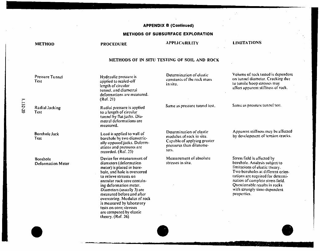
Pressure TunnelTest
Radial JackingTest
Borehole JackTest
BoreholeDeformation Meter
Hydraulic pressure isapplied to sealed-offlength of circulartunnel, and diametraldeformations are measured.(Ref. 21)
Radial pressure is appliedto a length of circulartunnel by flat jacks. Dia-metral deformations aremeasured.
Load is applied to wall ofborehole by two diametric-ally opposed jacks. Deform-ations and pressures arerecorded. (Ref. 25)
Device for measurement ofdiameters (deformationmeter) is placed in bore-hole, and hole is overcoredto relieve stresses onannular rock core contain-ing deformation meter.Diameters (usually 3) aremeasured before and afterovercoring. Modulus of rockis measured by laboratorytests on core; stressesare computed by elastictheory. (Ref, 26)
Determination of elasticconstants of the rock massin situ.
Same as pressure tunnel test.
Determination of elasticmodulus of rock in situ.Capable of applying greaterpressures than dilatome-ters.
Measurement of absolutestresses in situ.
Volume of rock tested is dependenton tunnel diameter. Cracking dueto tensile hoop stresses mayaffect apparent stiffness of rock.
Same as pressure tunnel test.
Apparent stiffness may be affectedby development of tension cracks.
Stress field is affected byborehole. Analysis subject tolimitations of elastic theory.Two boreholes at different orien-tations are required for determi-nation of complete stress field.Questionable results in rockswith strongly time-dependentproperties.

APPENDIX B (Continued)
METHODS OF SUBSURFACE EXPLORATION
METHOD PROCEDURE APPLICABILITY LIMITATIONS
METHODS OF IN SITU TESTING OF SOIL AND ROCK
InclusionStressmeter
Borehole StrainGauge
IL-)
Rigid stress indicatingdevice (stressmeter) isplaced in borehole, andhole is overcored torelieve stresses on annu-lar core containing stress-meter. In situ stressesare computed by elastictheory. (Ref. 26)
Strain gauge is cementedto bottom (end) of bore-hole. and gauge is over-cored to relieve stresseson core containing straingauge. Stresses are computedfrom resulting strains andfrom modulus obtained bylaboratory tests on core.(Ref. 26)
Slot is drilled in rocksurface producing stressrelief in adjacent rock.Flat jack is grouted intoslot and hydraulicallypressurized. Pressurerequired to reversedeformations produced bystress relief is observed.(Refs. 26. 27)
Measurement of absolutestresses in situ. Requiresonly one core drill size.
Measurement of one corn po-nent of normal stress insitu. Does not requireknowledge of rock modulus.
Same as above.
Stress field is affected byexcavation or tunnel. Interpre-tation of test results subjectto assumption that loading andunloading moduli are equal.Questionable results in rockwith strongly time-dependentpruperties.
Measurement of absolutestresses in situ. Doesnot require accurate knowl-edge of rock modulus.
Same as above.
Flat Jack Test

APPENDIX B (Continued)
METHODS OF SUBSURFACE EXPLORATION
METHOD PROCEDURE APPLICABILITY LIMITATIONS
METHODS OF IN SITU TESTING OF SOIL AND ROCK
HydraulicFracturing Test
CrossholeSeismic Test
Uphole/DownholeSeismicTest
Acoustic VelocityLog
Fluid is pumped into scaled-off portion of boreholewith pressure increasinguntil fracture occurs.(Ref. 26)
Seismic signal is trans-mitted from source inone borehole to receiv-er(s) in other bore-hole(s), and transittime is recorded. (Ref. 28)
Seismic signal istransmitted betweenborehole and groundsurface, and transittime is recorded. (Ref. 28)
Logging tool containstransmitting transducerand two receiving trans-ducers separated by fixedgage length. Signal istransmitted through rockadjacent to borehole andtransit time over thegage length is recordedas difference in arrivaltimes at the receivers.(Refs. 29. 30)
In situ measurement of com-pression wave velocity andshear wave velocity in soilsand rocks.
In situ measurement of com-pression wave velocity andshear wave velocity in soilsand rocks.
Measurement of compressionwave velocity. Used primar-ily in rocks to Obtainestimate of porosity.
Requires deviation survey ofboreholes to eliminate errorsdue to deviation of holes fromvertical. Refraction of signalthrough adjacent high-velocitybeds must be considered ininterpretation.
Apparent velocity obtained istime-average for all stratabetween source and receiver.
Results represent only thematerial immediately adjacentto the borehole. Can be obtainedonly in uncased, fluid-filledborehole. Use is limited tomaterials with P-wave veloritygreater than that of boreholefluid.
Estimation of minor principalstress.
Affected by anisotropy of tensilestrength of rock.
0

APPENDIX B (Continued)
METHODS OF SUBSURFACE EXPLORATION
METHOD PROCEDURE A PPIJCABSILITY ILIMITATIONS
METHODS OF IN SITU TESTING OF SOIL AND ROCK
3-D VelocityLog
ElectricalResistivityLog
Logging tool containstransmitting transducerand receiving transducerseparated by fixed gagelength. Signal is trans-mitted through rockadjacent to borehole. andwave train at receiveris recorded. (Ref. 31)
Apparent electrical resis-tivity of soil or rock inneighborhood of boreholeis measured by in-holelogging tool containingone of a wide variety ofelectrode configurations.(Refs. 29. 30)
Measurement of compressionwave and shear wave velocityties in rock. Detection ofvoid spaces. open fractures,and zones of weakness.
Appropriate combinations ofresistivity logs can be usedto estimate porosity and degreeof water saturation in rocks.In soils, may be used asqualitative indication ofchanges in void ratio orwater content, for correla-tion ofstrata betweenboreholes, and for locationof strata boundaries.
Correlation of stratabetween boreholes andlocation of strataboundaries. Provides anapproximation to watercontent and can be run incased or uncased, fluid-filled or empty boreholes,
Results represent only thematerial immediately adjacentto the borehole. Can be obtainedonly in uncased, Iluid-filledborehole. Correction requiredfor variation in hole size. Useis limited to materials with P-wave velocity greater than thatof borehole fluid.
Can be obtained only in uncasedborcholes. Hole must be fluidfilled, or electrodes must bepressed against wall of hole.Apparent resistivity values arestrongly affected by changes inhole diameter, strata thickness,resistivity contrast between adja-cent strata. resistivity ofdrilling fluid, etc.
Because of very strong boreholeeffects, results are generallynot of sufficient accuracy forquantitative engineering uses.
t-J
Neutron Log Neutrons are emitted intorock or soil around bore-hole by a neutron sourcein the logging tool, anda detector isolated fromthe source responds toeither slow neutrons orsecondary gamma rays.Response of detector isrecorded. (Refs. 29. 30)

APPENDIX B (Continued)
METHODS OF SUBSURFACE EXPLORATION
METHOD PROCEDURE APPLICA BILITY IEMITATIONS
METHODS OF IN SITU TESTING OF SOIL AND ROCK
Gamma-Gamma Log("Density Log")
Gamma rays are emittedinto rock around theborehole by a source inthe logging tool, and adetector isolated fromthe source responds toback-scattered gammarays. Response of de-tector is recorded.(Ref. 29)
Film-type or televisioncamera in a suitableprotective containeris used for observationof walls of borehole.(Ref. 32)
Estimation of bulk densityin rocks, qualitative indi-cation of changes in densi-ty of soils. May be run inempty or fluid-Filled holes.
Detection and mapping ofjoints, seams, cavities, orother visually observablefeatures in rock. Can beused in empty, uncased holesor in holes filled withclear water.
Effects of borehole size anddensity of drilling fluid mustbe accounted for. Presentlynot suitable for qualitativeestimate of density in soilsother than those of -rock-like"character. Cannot be used incased boreholes,
Results are affected by anycondition that affects visi-bility.
4'" BoreholeCameras

APPENDIX C
SPACING AND DEPTH OF SUBSURFACE EXPLORATIONS FOR SAFETY-RELATED' FOUNDATIONS
TYPE OF STRUCTURE
General
SPACING OF BORINGS' OR SOUNDINGS
For favorable, uniform geologic conditions, wherecontinuity of subsurface strata is found. spacing shouldbe as indicated for the type of structure with at least oneboring at the location of every safety-related or SeismicCategory I structure. Where variable conditions arefound, spacing should be smaller, as needed, to obtain aclear picture of soil or rock properties and theirvariability. Where cavities or other discontinuities ofengineering significance may occur, the normalexploratory work should be supplemented by borings orsoundings at a spacing small enough to detect suchfeatures.
tb.j
MINIMUM DEPTH OF PENETRATION
The depth of borings should be determined on the basisof the type of structure and geologic conditions. Allborings should be extended to a depth sufficient todefine the site geology and to sample all materials thatmay swell during excavation, may consolidatesubsequent to construction, may be unstable underearthquake loading, or whose physical properties wouldaffect foundation behavior or stability. Where soils arevery thick, the maximum required depth for engineeringpurposes, denoted dmax, may be taken as the depth atwhich the change in the vertical stress during or afterconstruction for the combined foundation loading is lessthan 10% of the in situ effective overburden stress. Itmay also be taken as the depth at which the shear wavevelocity of the soil mass exceeds 3.000 ft/sec. It may benecessary to include in the investigation program severalborings needed to complete information to establish thesoil model for soil-structure interaction studies. Theseborings may be required to penetrate depths greaterthan those depths required for general ený;inecringpurposes. Borings should be deep enough to define andevaluate the potential for deep soil stability problems atthe site. Generally all borings should extend at least 30feet below the lowest part of the foundation. Ifcompetent rock is encountered at lesser depths thanthose given, borings should penetrate to the greatestdepth where discontinuities or zones of weakness canaffect foundations and should penetrate at least 20 ftinto sound rock. For weathered shale or soft rock.depths should be as for soils.
'As dctcrmincd by I tt'jt1 lii ocaiiivns of .,ife .-relted structure.- and facififics.
'Includc. shafts or other accessible excvations that meet depth requirements.

APPENDIX C
SPACING AND DEPTH OF SUBSURFACE EXPLORATIONS FOR SAFETY-RELATED 3 FOUNDATIONS
TYPE OF STRUCTURE
Structures includingbuildings, retaining walls.concrete dams.
Earth dams, dikes, levees,and embankments.
Deep cuts, 6 canals
SPACING OF BORINGS4 OR SOUNDINGS
Principal borings: at least one boring beneath everysafety-related structure. For larger, heavier structures,such as the containment and auxiliary buildings, at leastone boring per 10,000 sq ft (approximately 100 ftspacing) and, in addition, a number of borings along theperiphery, at corners, and other selected locations. Oneboring per 100 linear ft for essentially linear structures.?
Principal borings: one per 100 linear ft along axis ofstructure and at critical locations perpendicular to theaxis to establish geological sections and groundwaterconditions for analysis.'
Principal borings: one per 200 linear ft along thealignment and at critical locations perpendicular to thealignment to establish geologic sections for analysis.!
MINIMUM DEPTH OF PENETRATION
Principal borings: at least one-fourth of the principalborings anid a minimum of one boring per structure topenetrate into sound rock or to a depth equal to dmax.Others to a de;th below foundation elevation equal tothe width of structure or to a depth equal to thefoundation depth below the original ground surface.whichever is greater.'
Principal borings: one per 200 linear ft to dmax. Othersshould penetrate all strata whose strength would affectstability. For water-impounding structures, to sufficientdepth to define all aquifers and zones of underseepagethat could affect performance of structure.-
Principal borings: one per 200 linear ft to penetrate intosound rock or to dmax. Others to a depth below thebottom elevation of"cavation equal to the depth of cutor to below, the lowest potential failure zone of theslope.! Borings should penetrate pervious strata belowwhich groundwater may influence stability.
0%
AIso supplementary borings or soundings which are design dependent or nccessary to define anomalies. critical abutment conditions. etc.
Includes temporary cuts, open during construction. where loss of strength due to excessive deformations would affect ultimate site safety.
0

_____ - -- ____
APPENDIX C
SPACING AND DEPTH OF SUBSURFACE EXPLORATIONS FOR SAFETY-RELATED3 FOUNDATIONS
TYPE OF STRUCTURE
Pipelines
Tunnels
SPACING OF BORIN(;S4 OR SOUNDINGS
Principal borings: This may vary depending on how wellsite conditions are understood from other plant siteborings. For variable conditions, one per 100 linear ftfor buried pipelines: at least one boring for each footingfor pipelines above ground.'
Principal borings: one per 100 linear ft.'
MINiNMUM DEPTH OF PENETRATION
Principal borings: For buried pipelines, one per 200linear ft to penetrate into sound rock or to dmax. Othersto 5 times the pipe diameters below the invert elevation.For pipelines above ground. depths as for foundationstructures.
Principal borings: one per 200 linear ft to penetrate intosound rock or to diiax. Others to 5 times the tunneldiameter below the invert elevation,'
1.-j-j
Reservoirs, impoundments Principal borings: one per 50,000 ft' of interior area ofthe impoundment. in addition to borings at thelocations of dams or dikes.'
Principal borings: at least one-fourth. but no fewer thanone, of the principal borings to penetrate into soundrock or to dmax. Others to a depth of 25 ft belowrc.esrvoir bottom elevation.'
, Stippkllcn~iery horing, o~r %on ing ai nce'%JrY to define zin-naliics.

APPENDIX D
REFERENCES
1. U.S. Army Corps of Engineers, Instrumentationof Earth and Rock-Fill Dams (Groundwater and PorePressure Observations), Engineer Manual EM 1 110-2-1908. 1972.
2. U.S. Army Corps of Engineers, Soil Sampling.Engineer Manual EM 1110-2-1907. 1972, Ch. 3, 4.
3. U.S. Navy, Design Manual, Soil Mechanics,Founidations, andl Earth Structures. A',-1 VF,,l C DM-7.Dept. of the Navy, Naval Facilities EngineeringCommand. Alexandria. Virginia, 1971.
4. Osterberg, J.O., and S. Varaksin, "Determina-tion of Relative Density of Sand Below GroundwaterTable.~ Evaluation of Relative Densit' and Its Role inGeotechnical Projects inrowiving Cohesiohless Soils.American Society for Testing and Materials.Philadelphia. STP 523. 1973, pp. 364-376.
5. Karol. R. H.. "Use of Chemical Grouts to Sam-pie Sands,~ Sampling of Soil adl Rock, AmericanSociety for Testing and Materials, Philadelphia, STP483, 19•71. pp. 51-59.
6. Windisch. S. J.. and M. Soulie. "Technique forStudy of Granular Materials." J. Soil Mlech. Found.Dir.. American Society of Civil Engineers. V. 96(SM4). 1970, pp. 1113:1126.
7. Hvorslev. IM. J.. Subsurface Exploration andSampling o0 Soils .lr Civil Engineering PurposeS. U.S.Army Waterways Experiment Station, Vicksburg,Mississippi. 1949. pp, 51-71. 83-139, 156-157.
8. Barton. C. MI.. "Borehole Sampling ofSaturated Uncemented Sands and Grouts,"Groundwater 12(3). 1974. pp. 170-181.
9, A merican Society for Testing and Materials,1974 .I ntunl Book of' ,.ISTAI S.S'wlftr ls' Port' 19.Philadelphia. 1974, pp. 192,194. 206-207, 224-229.261.263, 317-320.
uo•rings,' Special proC'lhires),or T'sfing sait (o41Rock' or Engiineering Purposes. American Society forTesting and Materials, Philadelphia, STP 479, 1969,
Ii. Peck. R. B.. W. E. Hanson, and T. 11,Thorn-burn. Foundation Engineering. John Wiley and Sons,Inc.. New York, 2nd ed.. 1974. pp. 105-106.
12, U.S. Dept. of Interior, Bureau of Reclamation,Earth Manual, Ist ed.. Denver, Colorado, 1960, pp.346-379.
13. Terziaghi. K.. and R. B. Peck. Soil Alechlnicsin Engineering Practice. 2nd ed., John Wiley andSons, Inc., New York. 1963. pp. 299-300.308-314.322-324.
14. Osterberg. J. 0., "New Piston Type SoilSampler.'* Engineering Newiv-Record 148. 1952, pp.77-78.
15. Kjellman, W.. T. Kallstanins, and 0. Wager."Soil Sampler with Metal F",<,,- Royal SwedishGeotechnical Institute. Proceeding No. I.Stockholm. Sweden. 1950.
16. Rocha. M., "A Method of Obtaining IntegralSamples of Rock Masses," Association of Engineer-ing Geologists. Bulletin• 10(I). 1973. pp. 77-82,
17. Tirez. G. B.. "Recent Trends in UnderwaterSoil Sampling Methods." Underwater Soil Samtpling.Testing. and Construction Control. American Societyfor Testing and Materials. Philadelphia. STP 501.1972. pp. 42-54.
18. Nooranz. I., "Underwater Soil Sampling andTesting-A State-of-the-Art Review." UnderwaterSoil Sampling. Testing, and Construction Control.American Society for Testing and Materials,Philadelphia. STP 501, 1972. pp. 3-41.
19. McCoy, F. W., Jr., "An Analysis of PistonCoring Through Corehead Camera Photography',"Underwater Soil Sampling. Testing. and ConstructionControl. American Society for Testing and Materials.Philadelphia, STP 501, 1972. pp. 90-105.
20. Schmertmann. J. H., "Suggested Method forDeep Static-Core Penetration Test." Speciall'roc&'durt's fi)r Testilng Soil anil Rock otr ligitlcr'irhgPurposes, American Society for Testing a11dMaterials, Philadelphia. STI1 479, 1970. pp. 71-77,
IL stio K, (1,, "111 8i4t1 " (m 1 the I ck
Sons, Inc,, Now York, Ch. 5, 1968K pp. 126-144,
22. Cedergrvn, H, R., Seepage. Drainage, and Flow
D3. Sead'im, 3. L.. "Inflone~c of" hnestim tl'l. \Vileron the Behavior of Rock Masses." Rock Mechanics inEngineering Practice. K. G. Stagg and 0. C.
132-28
( 1

I
ZienkiewicL, eds., John Wiley and Sons, Inc., NewYork, 1968, Ch. 3.
24, D)odds, R. K., "Suggested Method of Test forIn Situ Shear Strength of Rock." Special lProcedures
.lr Testing Soil wdl Rock jor Engineering Purposes.American Society for Testing and Materials,Philadelphia, STP 479. 1970, pp. 618-628.
25. Goodman. R. E.. T. K. Van, and P. E. Henze."Measurement of Rock Deformability in Bore-holes.** Proceedings ofthe Tenth Symposiumn on RockMlechanics, A.fustin, Texas. 1968. pp. 523-555.
26. Roberts. A.. "The Measurement of Strain andStress in Rock Masses,'" Rock Mechanics in Engineer-ing Practice. K. G. Stagg and 0. C. Zienkiewicz. eds.,John Wile), and Sons. Inc., New York, 1968, pp. 166-191, 194.
27. Rocha. M., "New Techniques in Delor-mability Testing or In Situ Rock Masses," Deter-inination of the in Situ Atodiduvs of Deformation of
Rock, American Society for Testing and Materials,Philadelphia. STP 477, 1970.
28. Ballard. R. F., Jr. and F. G. McLean, "SeismicField Methods for In Situ Moduli," in Situ Measure-
nerit of Soil Properties. Proceedings of the SpecialtyConference of the Geotechnical Engineering Divi-sion. American Society of Civil Engineers. Raleigh,North Carolina, 1975, pp. 121-150.
29. Schlumberger Ltd.. Log Interpretations. Vol.I (Principles), Schlumberger. Ltd., New York. 1972.Ch. 3-9.
30. Haun, J. D., and L. W. Leroy. editors, Subsur-face Geology in Petroleum Exploration. A. Sjionposiwt.Colorado School of Mines. Golden. Colorado, Ch.14. 15, 21. 1958.
31. Gever, R. L. and J. I Myung. "The 3-DVelocity Log: a Tool for In Situ Determination of theElastic Moduli of Rocks." Proceedings ofthe TweljihSymposi .111on Rock AMechanics. Rolla/. Missouri.1971, pp. 71-107.
32. Lundgren. R., F. C. Sturges. and L. S. Cluff."General Guide for Use of Borehole Cameras-AGuide." Special Procedures for Testing Soil anil Rockfor Engineering Purposes. American Society forTesting and Materials, Philadelphia. STP 479. 1970.pp. 56-61.
1.132-29

APPENDIX E
BIBLIOGRAPHY
Bates. E. R.. "I)Deection of Subsurface Cavities."MI iscellaneous Paper. S-73-40. U.S. A rm \VaterwaysI-xperiment Station. Vicksburg. NIississippi. 1973.
Calhoon. NI. [.. "'Pressurc-.Mctcr Field Tcsting ofSoils." Civil E'ntgine'ring 39(7), 1969. pp. 71-74.
(;hIssop. R.. "-The Rise of Geotechnology and ItsInillnence on I-neineering Practice.'" Ieihtlh RankineLeclure: Gvcechnique 1iI,2), 1968. pp. 105-150.
Hlall. W. J.. N. M. Newmark. and A. J. Hendron..Jr.. "Classification. Elngineering Properties and FieldExploratioll of Soils, Intact Rock. and In Situ Mas-s.es.'" US. AEC Report WASH-130). 1974.
iMisterek. 1). L., "'Analysis of Dlata from RadialJack in Tests.-" /)eet'rmiaiiog tlf the In Sint .Mthldultof I)Ml10rmnlclion of Rock. American Societv IforTesting and MIate-,ials. Plhiladelphia. STI' 477. 1970.pp, 27-38.
Osterberg, .1. 0.. "An Improved Ilydraulic PistonSampler." Proceedings olf the Eihth /Inerlariona alCOnh'rrence on Soil Aflechanics aniid Fotundatlionh'ngin'erinr, Mloscow. LUSSR, Vol. 1.2. 1973. pp. 317-321.
Sh1a.nllnon. Wilson. Inc., and Agbahian-.lacobsenAssociates, "'Soil Behavior Under IEarthquakel.oading Conrditions: State-of-tle-A rt -valuatil tof"Soil Characteristics fur Seismic Response An:iy.sis.'U.S. .\I:C Report. 1972.
Task Committee for Foundation D)esign Manual."'SUbsurface In\Vest6iation for I)esiun and Construc-ion of' Foundations of Buildi ngs.'" .. 1oil Alech.Fo"und. lv.. A\merican Society of Civil I-ngincers.1972. V. 98(SM5): pp. 481-490. V.98(SN16: pp. 557-578. V. 98(SNI!7): pp. 749-764. V. 9,(SNIX): pp. 771-785.
Wallace. G. 11.. I. .1. Slehir. and 1. :A. Anderson.-Radial Jacking Test for Arch Dams." !'roceedingsof Mie 1*'0ih S/.rmtp.iti on R j( A .I•chi'mic.. .k.Aut11in.
1968. pp. 633-660.
01.132-30