regulation of synchronous generator_saravanan t y_electrical machines-iii
DESCRIPTION
Regulation of Synchronous Generator_Saravanan T Y_Electrical Machines-III_3 Unit_As per JNTUA with Solved ProblemsTRANSCRIPT

Electrical Machines-III Regulation of Synchronous Generator
T. Y. Saravanan M. Tech., NEC∷GUDUR 92
UNIT – IIi
33.. RREEGGUULLAATTIIOONN OOFF SSYYNNCCHHRROONNOOUUSS GGeenneerraattoorr
3.1. Voltage Regulation:
The variation in the voltage between no-load and full-load is called the voltage regulation.
As we know that the voltage regulation of dc generator should depends on,
i. the resistance the main or armature circuit
ii. the magnitude of the armature current
iii. the armature reaction (i.e., the effect of the armature flux on main flux) In case of the synchronous generator or alternator, in addition to above 3 factors in dc generator,
the voltage regulation depends upon the power factor and armature leakage reactance also.
Voltage Regulation of an alternator is defined as the ratio of “rise in voltage (E0-V) when full-
load is removed (field excitation and speed remaining the same) to the rated terminal voltage.
Rise in voltage = ‘E0-V’ is the arithmetic difference not the vector difference.
E0 = Maximum no-load induced emf magnitude
V = Terminal voltage of an alternator.
Voltage regulation depends on power factor ‘cos ’
∴ % Regulation 'up' = E0- V
V × 100
If we can change the load of an alternator, there is a change in terminal voltage (V). The
magnitude of terminal voltage change depends on,
i. load can changes, the terminal voltage magnitude changes and the power factor (cos∅)
also. [ since V = E - Ia (Re + j Xs) ]
ii. excitation can changes, the magnitude of terminal voltage changes (V).
In case of leading load power factor, terminal voltage (V) will fall on removing full-load. At
lower leading load power factor ‘v ‘ rises with the increase of load, and hence the regulation is
‘-ve’.
For unity and lagging power factors, there is always a voltage drop with increase of load.
The rise in voltage when full-load is removed is not same when full-load is applied.
Note: 1). V < E0, i.e., the voltage regulation is POSITIVE for LAGGING & UNITY power factor
loads.
2). V > E0, i.e., the voltage regulation is NEGATIVE for LEADING power factor loads.
Electrical Machines-III Regulation of Synchronous Generator
T. Y. Saravanan M. Tech., NEC∷GUDUR 93
3). A normal alternator has a regulation of about 8-10% at unity power factor (UPF), but
the voltage rise is considerably increased at lagging power factors. The regulation is about
23-35%, or even more
3.2. Determination of voltage regulation:
The following methods which are used to determine the voltage regulation i.e.,
I. Direct loading method (small rating machines i.e., ≤ 5 KVA)
II. Indirect loading method ( >5 KVA )
3.2.1. Direct loading method:
This method is applicable only for the alternators, which their rating is ≤ 5 KVA. Because for
medium and large rating alternators, it requires more power and more losses were occurred.
In this, the alternator is runs at synchronous speed (Ns) and its terminal voltage is adjusted to its
rated value (V). The load is varied until the ammeter, wattmeter indicates the rated values at
given power factor.
Then the load removed, the speed and excitation at kept at constant. The open circuit or no-load
induced emf recorded ‘E0’.
∴ % Voltage Regulation = E0- V
V × 100
3.2.2. Indirect loading method:
For large and medium rating (> 5 KVA) alternators, the regulation which can be determine by
using indirect loading method. Here the load is not applied directly but rated values are given to
alternator. There are various methods to determine the voltage regulation. Some of them ignore the
effect of saturation and some do consider. The following methods are used to obtain the voltage
regulation.
They are,
1. EMF or Synchronous Impedance or Pessimistic or Unsaturated Synchronous Impedance method
2. MMF or Ampere-Turns or ROTHERT’S Ampere-Turns or Optimistic method
3. Zero Power Factor or ZPF or Potier Triangle method
4. ASA (American Standards Association) method
All the above methods require,
a) Open Circuit or No-Load Characteristic Curve (OCC Curve)
b) Short Circuit Characteristic Curve (SCC Curve)
c) Armature effective resistance or Stator resistance (Re)
Electrical Machines-III Regulation of Synchronous Generator
T. Y. Saravanan M. Tech., NEC∷GUDUR 94
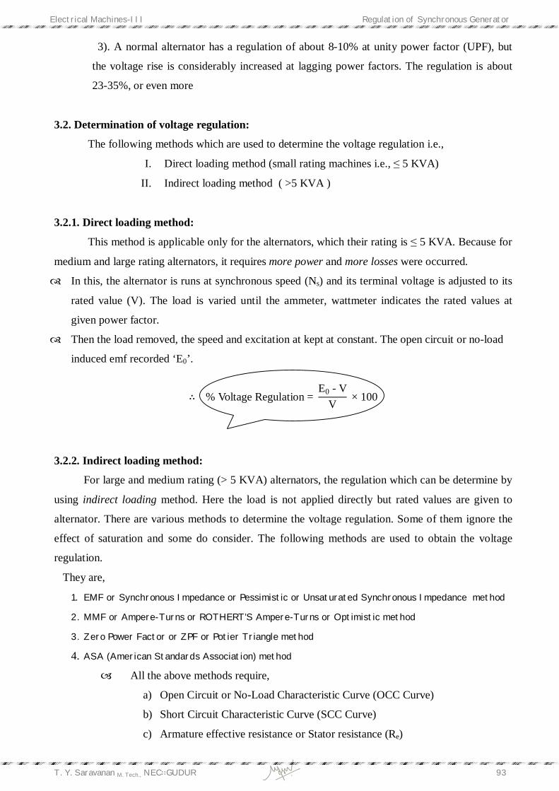
3.2.3. Open Circuit or No-Load Test: (To obtain OCC Curve)
The connection for Open Circuit test or No-Load test is shown in above circuit diagram. The
armature winding i.e., load terminals are opened and machine should be run at rated or
synchronous speed. The field winding is connected to dc source in series with a field rheostat
and an ammeter.
By adjusting the field rheostat from maximum to minimum, the field current If is taken through
ammeter in steps minimum to maximum respectively. Then Ego or no-load generated emf is also
reads minimum to maximum taken from voltmeter in steps up to rated value.
Draw the Open Circuit Characteristic Curve (OCC Curve) from the above readings. i.e., ‘If’ on
x-axis and Ego on y-axis. The Ego which we obtained from voltmeter is line value that should be
representing in a graph as phase value. i.e., [For a star connected armature, Ego/ph = Ego/line
√3 ].
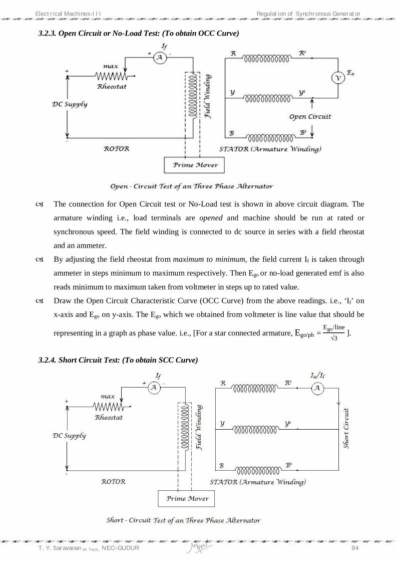
3.2.4. Short Circuit Test: (To obtain SCC Curve)
Electrical Machines-III Regulation of Synchronous Generator
T. Y. Saravanan M. Tech., NEC∷GUDUR 95
The connection for the short circuit test is shown in the above circuit diagram. In this test also
the machine should be maintained at constant speed by the prime mover.
All the 3- load terminals of 3- alternator as shorted. Rheostat of sufficiently high ohmic value is
inserted in the dc field circuit to keep the current in the circuit very low.
Now the field current ‘If’ is adjusted to Isc or Irated of 3- alternator by varying the field rheostat.
From the If and Isc the SCC Curve (Short Circuit Characteristic) is obtained.
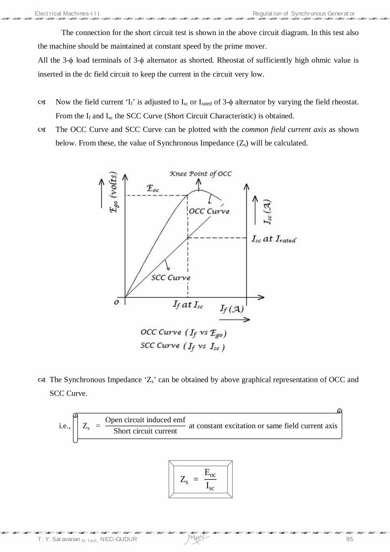
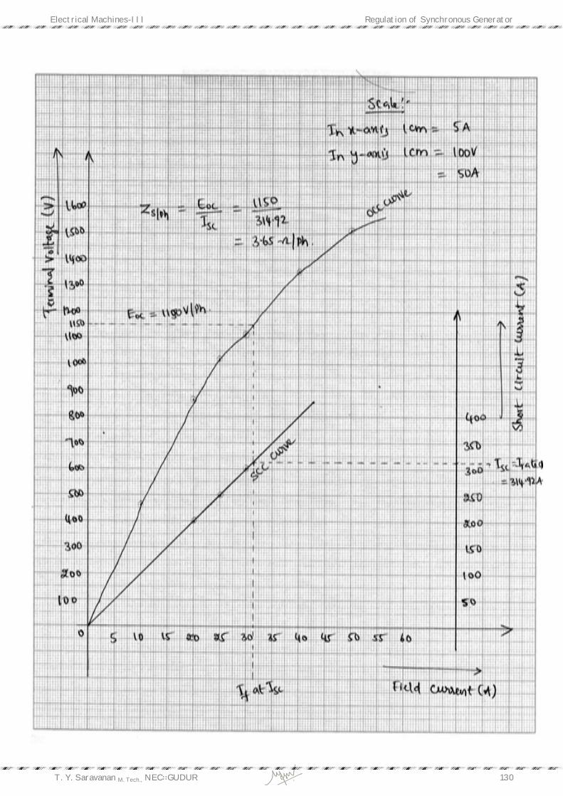
The OCC Curve and SCC Curve can be plotted with the common field current axis as shown
below. From these, the value of Synchronous Impedance (Zs) will be calculated.
The Synchronous Impedance ‘Zs’ can be obtained by above graphical representation of OCC and
SCC Curve.
i.e., Zs = Open circuit induced emf
Short circuit current at constant excitation or same field current axis
Zs = Eoc
Isc
Electrical Machines-III Regulation of Synchronous Generator
T. Y. Saravanan M. Tech., NEC∷GUDUR 96
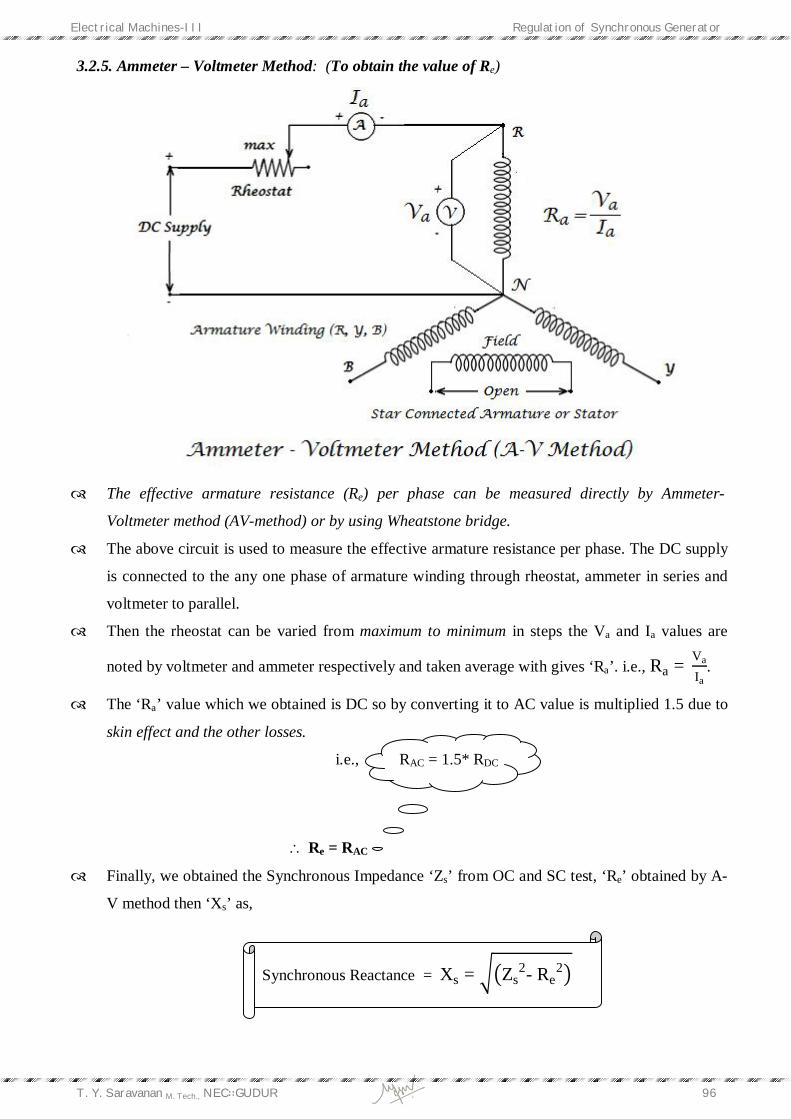
3.2.5. Ammeter – Voltmeter Method: (To obtain the value of Re)
The effective armature resistance (Re) per phase can be measured directly by Ammeter-
Voltmeter method (AV-method) or by using Wheatstone bridge.
The above circuit is used to measure the effective armature resistance per phase. The DC supply
is connected to the any one phase of armature winding through rheostat, ammeter in series and
voltmeter to parallel.
Then the rheostat can be varied from maximum to minimum in steps the Va and Ia values are
noted by voltmeter and ammeter respectively and taken average with gives ‘Ra’. i.e., Ra = Va
Ia.
The ‘Ra’ value which we obtained is DC so by converting it to AC value is multiplied 1.5 due to
skin effect and the other losses.
i.e., RAC = 1.5* RDC
Re = RAC
Finally, we obtained the Synchronous Impedance ‘Zs’ from OC and SC test, ‘Re’ obtained by A-
V method then ‘Xs’ as,
Synchronous Reactance = Xs = Zs2- Re
2

Electrical Machines-III Regulation of Synchronous Generator
T. Y. Saravanan M. Tech., NEC∷GUDUR 97
3.3. EMF method or Synchronous impedance method:
This method is also called as “Pessimistic or unsaturated synchronous impedance method.”
Assumptions:
In this method the assumptions are,
The drop due to armature reaction is considered as drop due to additional leakage reactance
means the entire drop assumed as drop due to leakage reactance (XL). IXL which depends on
voltage so that it can be represented as “Voltage Vectors or EMF Vectors”. That’s the reason
why this method is called as ‘EMF’ method.
The flux under test conditions is the same as that under load conditions.
The synchronous impedance (Zs) is constant. The Zs is determined by the OCC & SCC. At all
times, the Zs is the ratio of the open-circuit voltage to the short-circuit current. When the OCC
curve & SCC curve are linear, the synchronous impedance is constant. Above the knee of the
OCC when the saturation starts, the Zs decreases due to fact that both OCC & SCC approaches
to each other. The Zs obtained test condition is below saturation is larger than the normal (when
the magnetic circuit becomes saturated). Thus we do not take the effect of saturation. This is the
greatest source of error in the synchronous impedance method.
The magnetic reluctance to the armature flux is constant regardless of the power factor. For a
cylindrical rotor machine this assumption is true because of the uniform air-gap. In salient-pole
machines, the position of the armature flux relative to the field poles varies with the power
factor.
There is no saturation effect.
Steps to find the regulation:
i. OCC curve is plotted from the OC test. (refer OC test)
ii. SCC curve is drawn from the short-circuit test data (refer SC test). It is a straight line
passing through the origin.
Both these curve are drawn on a common field current (If) axis.
iii. Consider a field current (If) with respective to the short circuit current or full load current
‘Isc’ and draw a dotted line to that If which cuts occ at Eoc, the terminal voltage zero when
it is in short-circuit.
Zs = EocIsc
iv. Armature effective resistance can be obtained by A-V method (refer A-V method).
v. The synchronous reactance can be determined by,
Xs = Zs2- Re
2
Electrical Machines-III Regulation of Synchronous Generator
T. Y. Saravanan M. Tech., NEC∷GUDUR 98
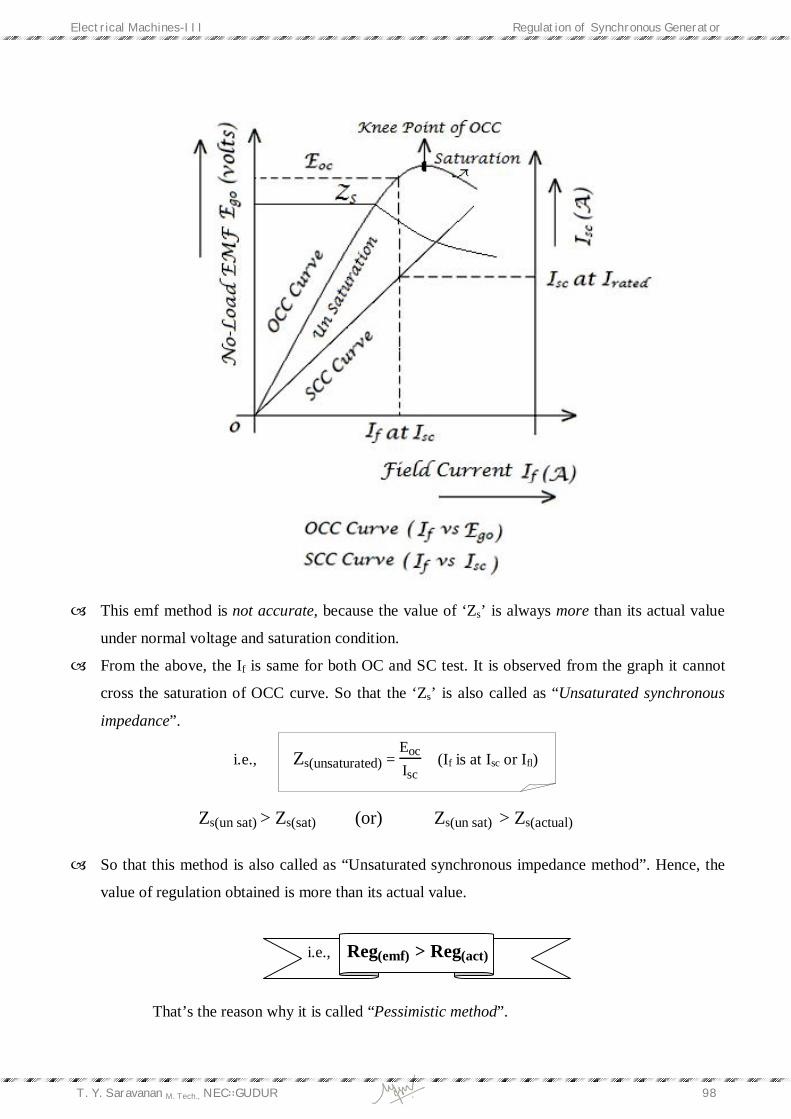
This emf method is not accurate, because the value of ‘Zs’ is always more than its actual value
under normal voltage and saturation condition.
From the above, the If is same for both OC and SC test. It is observed from the graph it cannot
cross the saturation of OCC curve. So that the ‘Zs’ is also called as “Unsaturated synchronous
impedance”.
i.e., Zs(unsaturated) = EocIsc
(If is at Isc or Ifl)
Zs(un sat) > Zs(sat) (or) Zs(un sat) > Zs(actual)
So that this method is also called as “Unsaturated synchronous impedance method”. Hence, the
value of regulation obtained is more than its actual value.
i.e., Reg(emf) > Reg(act)
That’s the reason why it is called “Pessimistic method”.

Electrical Machines-III Regulation of Synchronous Generator
T. Y. Saravanan M. Tech., NEC∷GUDUR 99
The value of ‘Zs’ is not constant; it can be varied with saturation. At low saturation or un
saturation its value is larger because then the effect of a given ampere-turns is more than that
high saturation.
Under short circuit condition, saturation is very low, because armature mmf is directly
demagnetizing.
In this method, the value of ‘Zs’ is usually obtained from full-load current in the short-circuit
test. Here, armature reactance ‘Xa’ has not been treated separately but taken along with leakage
reactance ‘XL’.
Value of ‘E0’ (for lagging load)
Considering load current (Ia) as a
reference, lagging load current ‘Ia’ is lags behind
the voltage (V) by an angle ‘‘.
From the Phasor diagram of lagging power
factor,
OD2 = OB2 + BD2
E02 = OD2 = (OA + AB)2 + (BC + CD)2
E0 = (V cos + IaRe)2+(V sin + IaXs)2
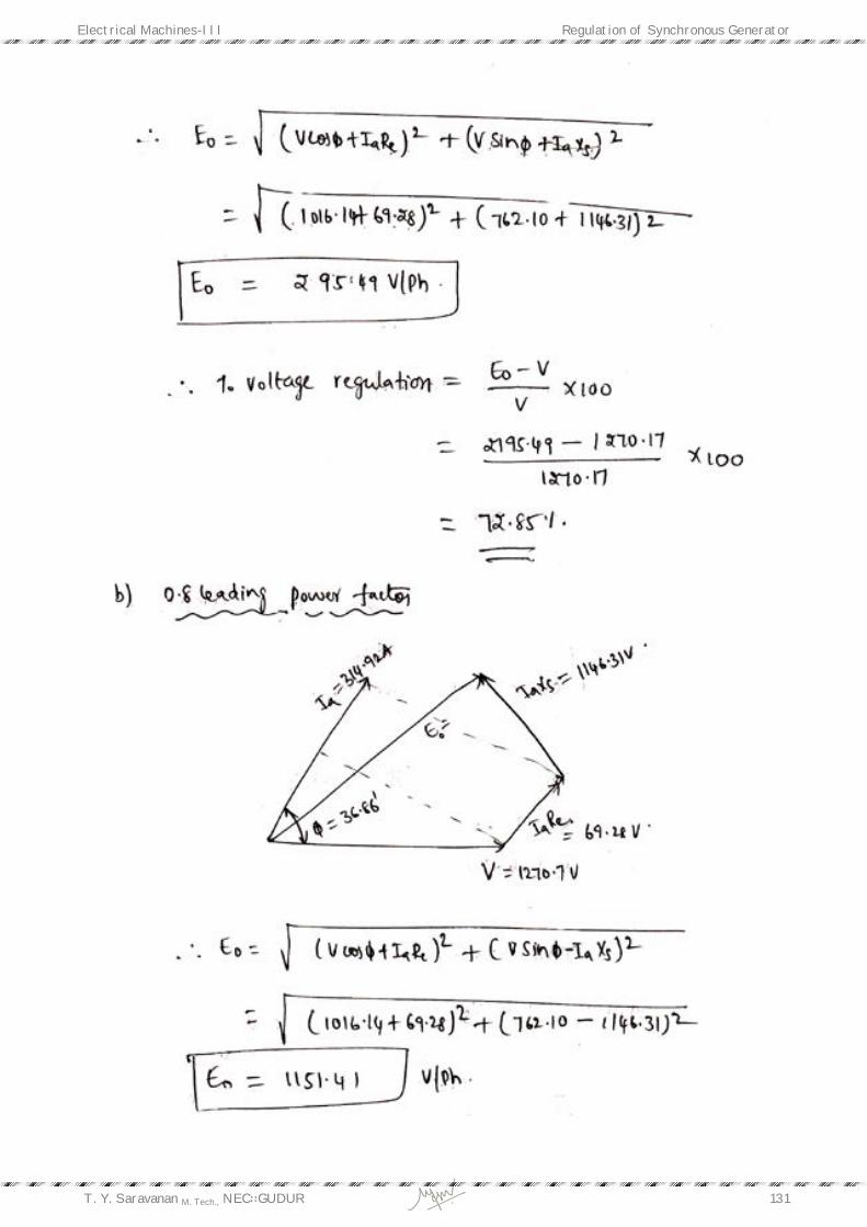
For leading load:
Consider terminal voltage (V) as a
reference, load current (Ia) leads terminal voltage
‘V’ by an angle ‘‘.
From the Phasor diagram of leading power factor,
OC2 = OD2 + DC2
E02 = OC2 = (OE + ED)2 + (BD - BC)2
E0 = (V cos + IaRe)2+ V sin - IaXs2

Electrical Machines-III Regulation of Synchronous Generator
T. Y. Saravanan M. Tech., NEC∷GUDUR 100
For Unity Power factor load:
Consider terminal voltage (V) and load
current (Ia) both are in phase i.e., ‘ = 00‘.
From the Phasor diagram of unity power
factor,
OD2 = OC2 + CD2
E02 = OD2 = (OB + BC)2 + (CD)2
E0 = (V+ IaRe)2+ (IaXs)2
% Voltage regulation = E0- VV
× 100 about 30%
Where, V = terminal voltage obtained by rating of an alternator.
3.4. MMF method or Ampere-Turn method: This method is also called as “ROTHERT’S MMF or Optimistic method”.
Assumptions:
The drop due to leakage reactance is considered as drop due to additional armature reaction
means entire drop is assumed to be drop due to armature reaction (IXa).
Since armature reaction is flux phenomena, so drop due to armature reaction is represented with a
“field current vectors (or) mmf vectors”. That is the reason why it is called as “MMF method”.
Steps to find the regulation:
i. OCC curve is obtained by conduction of OC test.
ii. SCC curve is obtained by conducting SC test i.e., field excitation is adjusted to full-load
current or short circuit current flows through short circuit path of an alternator load
terminals.
From the below,
Ifm is the main field current required to generate rated induced emf under Open-Circuit condition
Ifr is the main field current required to produce the armature or full load current under Short-
Circuit Condition
Electrical Machines-III Regulation of Synchronous Generator
T. Y. Saravanan M. Tech., NEC∷GUDUR 101
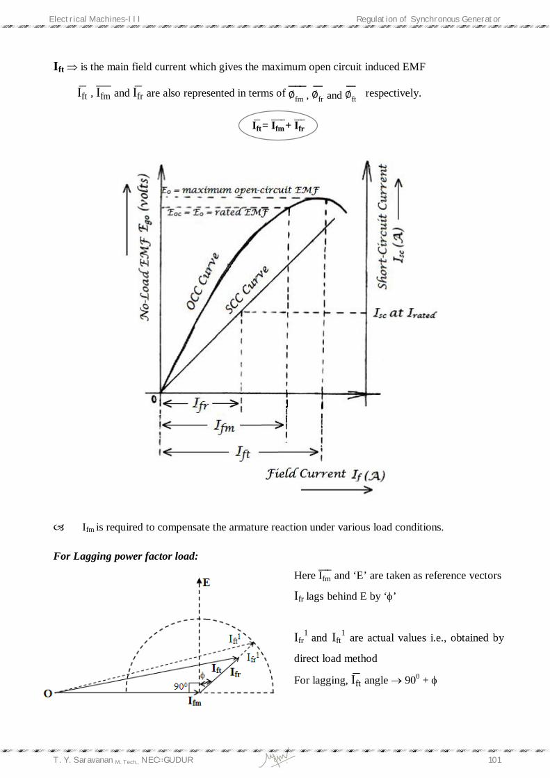
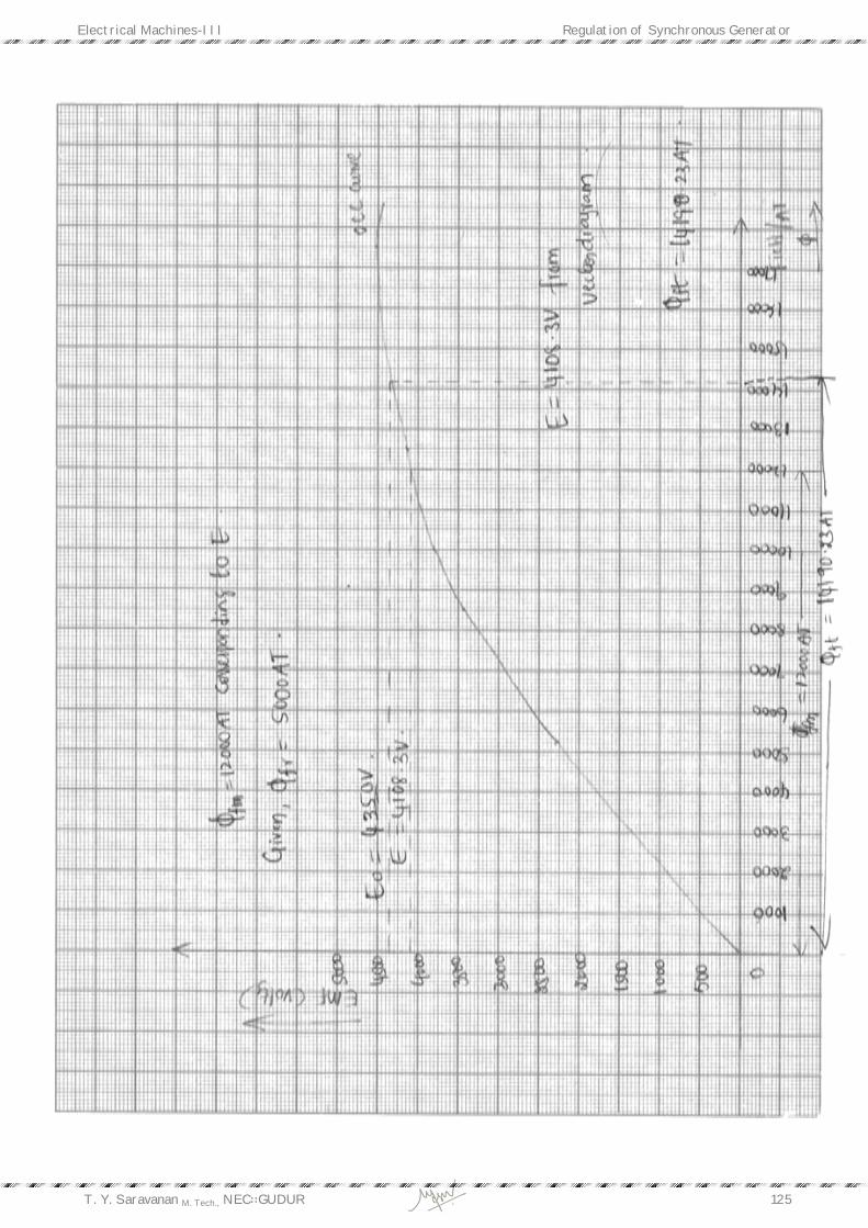
Ift is the main field current which gives the maximum open circuit induced EMF
Ift , Ifm and Ifrare also represented in terms of ∅fm , ∅fr and ∅ft respectively.
Ift= Ifm+ Ifr
Ifm is required to compensate the armature reaction under various load conditions.
For Lagging power factor load:
Here Ifm and ‘E’ are taken as reference vectors
Ifr lags behind E by ‘’
Ifr1
and Ift1 are actual values i.e., obtained by
direct load method
For lagging, Iftangle 900 +
Electrical Machines-III Regulation of Synchronous Generator
T. Y. Saravanan M. Tech., NEC∷GUDUR 102
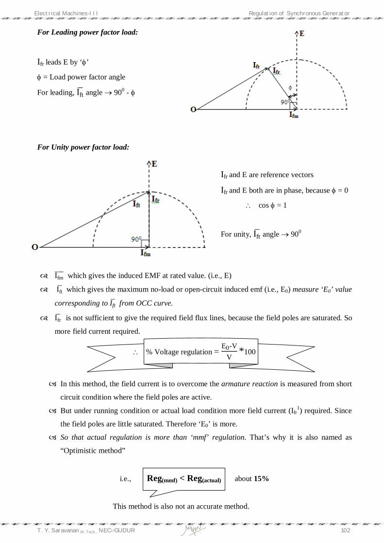
For Leading power factor load:
Ifr leads E by ‘’
= Load power factor angle
For leading, Iftangle 900 -
For Unity power factor load:
Ifr and E are reference vectors
Ifr and E both are in phase, because = 0
cos = 1
For unity, Iftangle 900
Ifm which gives the induced EMF at rated value. (i.e., E)
Ift which gives the maximum no-load or open-circuit induced emf (i.e., E0) measure ‘E0’ value
corresponding to Ift from OCC curve.
Ifr is not sufficient to give the required field flux lines, because the field poles are saturated. So
more field current required.
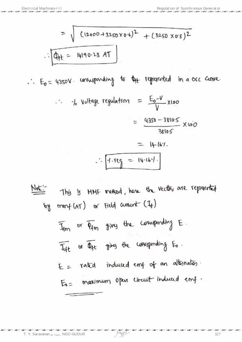
% Voltage regulation = E0-V
V*100
In this method, the field current is to overcome the armature reaction is measured from short
circuit condition where the field poles are active.
But under running condition or actual load condition more field current (Ifr1) required. Since
the field poles are little saturated. Therefore ‘E0’ is more.
So that actual regulation is more than ‘mmf’ regulation. That’s why it is also named as
“Optimistic method”
i.e., Reg(mmf) < Reg(actual) about 15%
This method is also not an accurate method.
Electrical Machines-III Regulation of Synchronous Generator
T. Y. Saravanan M. Tech., NEC∷GUDUR 103
3.5. Zero Power Factor (ZPF) or Potier Triangle or Power Triangle method: It makes use of the first two methods to some extent.
Assumptions:
In this method the assumptions taken are as follows i.e.,
Here the drop due to armature reactance (Xa) and leakage reactance (XL) are taken as
separately. Hence it gives the more accurate results.
The effective armature resistance (Re) is neglected.
The leakage reactance drop IaXL is independent of excitation.
The armature reaction mmf is constant.
The OCC taken on no-load accurately represents the relation between mmf and voltage on
load.
Steps to find the regulation:
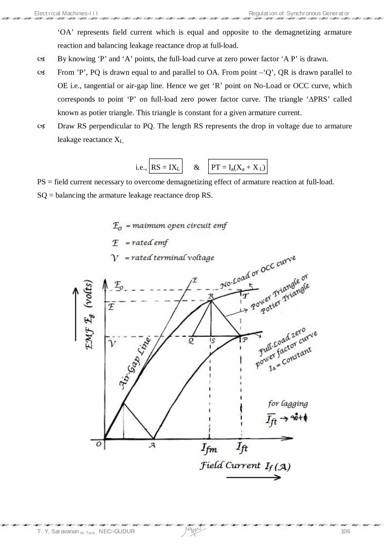
1. No-Load or Open Circuit Characteristic curve (OCC curve) obtained by OC test.
2. Full-Load zero power factor curve (not the SCC curve) also called the wattless load
characteristic. It is the curve of terminal voltage against excitation when armature is
delivering full-load current at zero power factor.
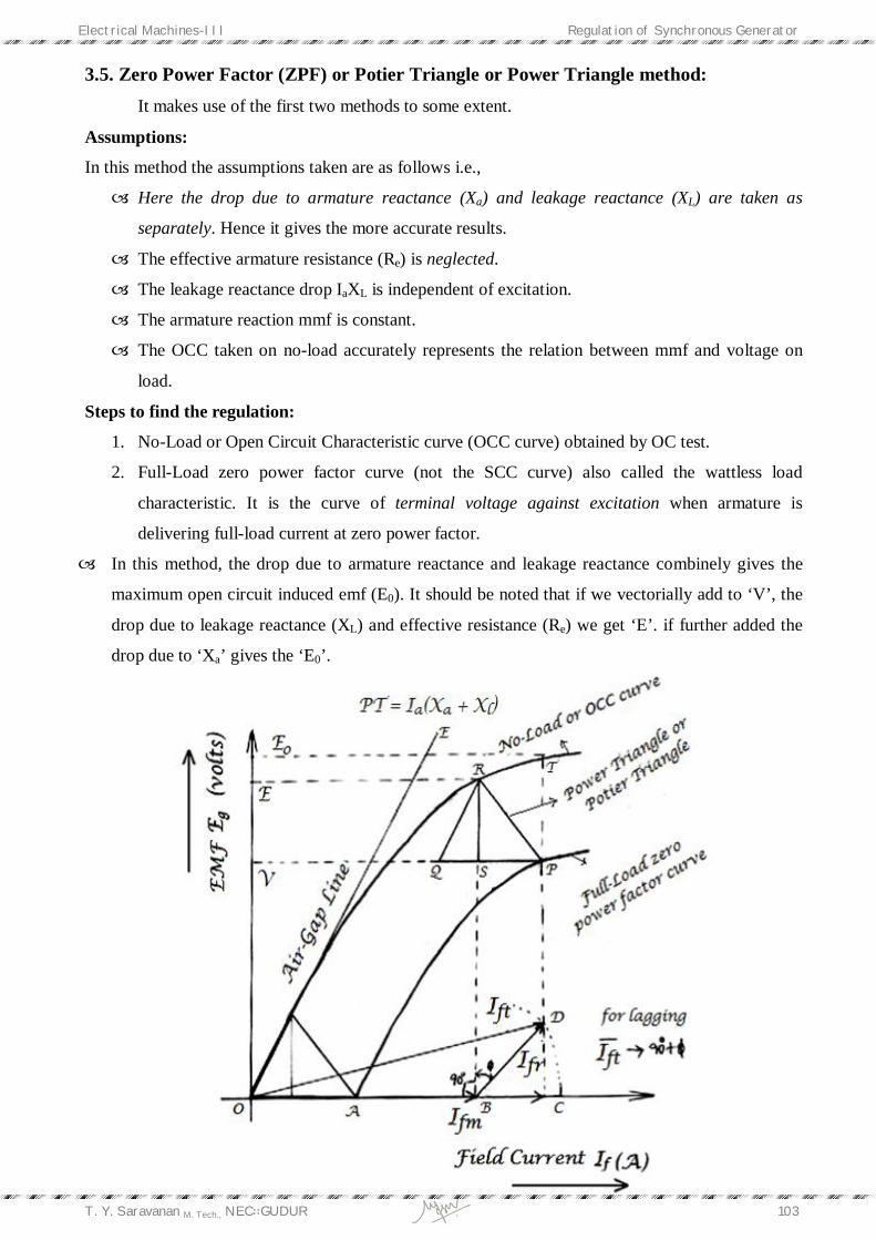
In this method, the drop due to armature reactance and leakage reactance combinely gives the
maximum open circuit induced emf (E0). It should be noted that if we vectorially add to ‘V’, the
drop due to leakage reactance (XL) and effective resistance (Re) we get ‘E’. if further added the
drop due to ‘Xa’ gives the ‘E0’.
Electrical Machines-III Regulation of Synchronous Generator
T. Y. Saravanan M. Tech., NEC∷GUDUR 104
The zero power factor full-load lagging curve can be obtained from,
a. If a similar machine is available, which may be driven at no-load as a synchronous motor
at practically zero power factor
b. Loading the alternators with pure reactors.
c. Connecting the alternators to a 3- line with ammeters and wattmeter’s connected for
measuring current and power, by so adjusting the field current that we get full-load
armature current with zero wattmeter reading.
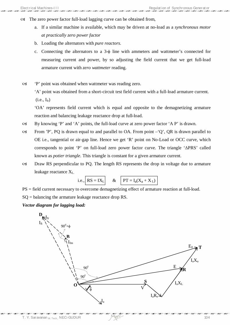
‘P’ point was obtained when wattmeter was reading zero.
‘A’ point was obtained from a short-circuit test field current with a full-load armature current.
(i.e., Ifr)
‘OA’ represents field current which is equal and opposite to the demagnetizing armature
reaction and balancing leakage reactance drop at full-load.
By knowing ‘P’ and ‘A’ points, the full-load curve at zero power factor ‘A P’ is drawn.
From ’P’, PQ is drawn equal to and parallel to OA. From point –‘Q’, QR is drawn parallel to
OE i.e., tangential or air-gap line. Hence we get ‘R’ point on No-Load or OCC curve, which
corresponds to point ‘P’ on full-load zero power factor curve. The triangle ‘∆PRS’ called
known as potier triangle. This triangle is constant for a given armature current.
Draw RS perpendicular to PQ. The length RS represents the drop in voltage due to armature
leakage reactance XL.
i.e., RS = IXL & PT = Ia(Xa + X L)
PS = field current necessary to overcome demagnetizing effect of armature reaction at full-load.
SQ = balancing the armature leakage reactance drop RS.
Vector diagram for lagging load:
IaRe
D
B
O
T
R
S
IaXa
IaXL
Ia
E0
E
V
900+
900
900
Ift Ifr
Ifm

Electrical Machines-III Regulation of Synchronous Generator
T. Y. Saravanan M. Tech., NEC∷GUDUR 105
The ∆OBD which is obtained from the graphical representation. For that,
OD2 = (OB+BC)2 + CD2
Ift = (Ifm+ Ifr sin )2+ (Ifr cos)2
% Voltage regulation = E0-V
V*100 about 20%
Similarly the vector or phasor diagrams for leading and unity power factor loads as mentioned in
MMF method. The value of E0 can be obtained with respective to Ift for voltage regulation.
3.6. ASA (American Standards Association) method: It is the combination of MMF and ZPF method and is a most accurate method. The drop
due to saturation also considered. In the EMF, MMF, ZPF methods the saturation is not considered.
Steps to find the regulation:
1. No-Load or Open Circuit Characteristic curve (OCC curve) obtained by OC test.
2. Full-Load zero power factor curve (not the SCC curve) also called the wattless load
characteristic considering saturation. It is the curve of terminal voltage against excitation
when armature is delivering current at zero power factor (Ia or IL = Constant).
In this method, the drop due to armature reactance and leakage reactance combinely gives the
maximum open circuit induced emf (E0). It should be noted that if we vectorially add to ‘V’,
the drop due to leakage reactance (XL) and effective resistance (Re) we get ‘E’. if further added
the drop due to ‘Xa’ gives the ‘E0’.
‘P’ point was obtained when wattmeter was reading zero.
‘A’ point was obtained from a short-circuit test field current with a full-load armature current.
(i.e., Ifr)
D
C B
900
E
O
Ift
Ifr
Ifm
Electrical Machines-III Regulation of Synchronous Generator
T. Y. Saravanan M. Tech., NEC∷GUDUR 106
‘OA’ represents field current which is equal and opposite to the demagnetizing armature
reaction and balancing leakage reactance drop at full-load.
By knowing ‘P’ and ‘A’ points, the full-load curve at zero power factor ‘A P’ is drawn.
From ’P’, PQ is drawn equal to and parallel to OA. From point –‘Q’, QR is drawn parallel to
OE i.e., tangential or air-gap line. Hence we get ‘R’ point on No-Load or OCC curve, which
corresponds to point ‘P’ on full-load zero power factor curve. The triangle ‘∆PRS’ called
known as potier triangle. This triangle is constant for a given armature current.
Draw RS perpendicular to PQ. The length RS represents the drop in voltage due to armature
leakage reactance XL.
i.e., RS = IXL & PT = Ia(Xa + X L)
PS = field current necessary to overcome demagnetizing effect of armature reaction at full-load.
SQ = balancing the armature leakage reactance drop RS.

Electrical Machines-III Regulation of Synchronous Generator
T. Y. Saravanan M. Tech., NEC∷GUDUR 107
Vector diagram for lagging load:
Ift
1 = field current to compensate drop due to saturation and is added in phase with Ift
Measure ‘E0’ corresponding to Ift1
.
% Voltage regulation = E0-V
V*100 about 25% to 28%
Similarly the vector or phasor diagrams for leading and unity power factor loads as
mentioned in MMF method. The value of E0 can be obtained with respective to Ift1 for voltage
regulation.
Note: Finally the Voltage Regulation of an Alternator as,
EMF method > ASA method > ZPF method > MMF method
i.e., we concluded that among the four methods the ASA & ZPF method will gives accurate
regulation compared to EMF & MMF
3.7. Two Reaction or BLONDEL Two Reaction theory:
Already we know that armature reaction is directly proportional to armature reactance
(Xa) and inversely proportional to air gap.
i.e., Air-Gap Length ∝ 1
armature reaction ∝
1Xa
In cylindrical type synchronous machine, the air-gap length is uniform. So the armature reaction
is same in between stator conductors and field poles. So ‘Xa’ is same i.e. single reactance is
sufficient for modeling the armature reaction.

Electrical Machines-III Regulation of Synchronous Generator
T. Y. Saravanan M. Tech., NEC∷GUDUR 108
In salient-pole type synchronous machine, air-gap is minimum in d-axis or direct-axis and
maximum in q-axis or quadrature or inter polar axis. So it requires both reactances i.e. Xd and Xq
for modeling the armature reaction.
In cylindrical rotor synchronous machine, the air-gap is uniform around the entire air-gap
periphery. So armature reaction is same along the d-axis and q-axis. So finally we concluded
that a single reactance is sufficient for modeling the armature reactance because Xd = Xq.
But in salient pole synchronous machine, the armature reaction is maximum in d-axis and
↓air-gap α 1
armature reaction↑
the armature reaction is minimum in q-axis.
↑air-gap α 1
armature reaction↓
So single reactance is not sufficient to modeling the armature reaction, it requires Xad and Xaq
i.e., Xd and Xq.
Xad > Xaq
Leakage reactance (XL) is same along d-axis and q-axis because it is independent of air-gap
length and dependent applied voltage and flux leakage. Therefore,
Xd = Xad + XL
Xq = Xaq + XL
Where,
Xd = direct axis synchronous reactance.
Xq = quadrature axis or interpolar axis synchronous reactance.
Electrical Machines-III Regulation of Synchronous Generator
T. Y. Saravanan M. Tech., NEC∷GUDUR 109
Xad = direct axis armature reactance.
Xaq = quadrature axis armature reactance.
XL = leakage reactance.
In general, Xd > Xq. i.e., Xd ≅ (1.5 to 2) times of Xq.
Xd - Xq = saliency. So that it is called as Salient pole synchronous machine.
For cylindrical type synchronous machine,
Xd - Xq = Zero saliency or non-saliency.
Because Xd = Xq due to uniform air gap.
That’s the reason why it is also called as Non-Salient pole type alternator.
3.8. Determination of Xd and Xq of a Salient pole synchronous machine:
The direct axis synchronous reactance (Xd) can be determined from OC and SC tests and
quadrature or interpolar axis synchronous reactance can be obtained from following three methods.
i.e., 1. Slip-test
2. Maximum – lagging current test
3. Reluctance motor.
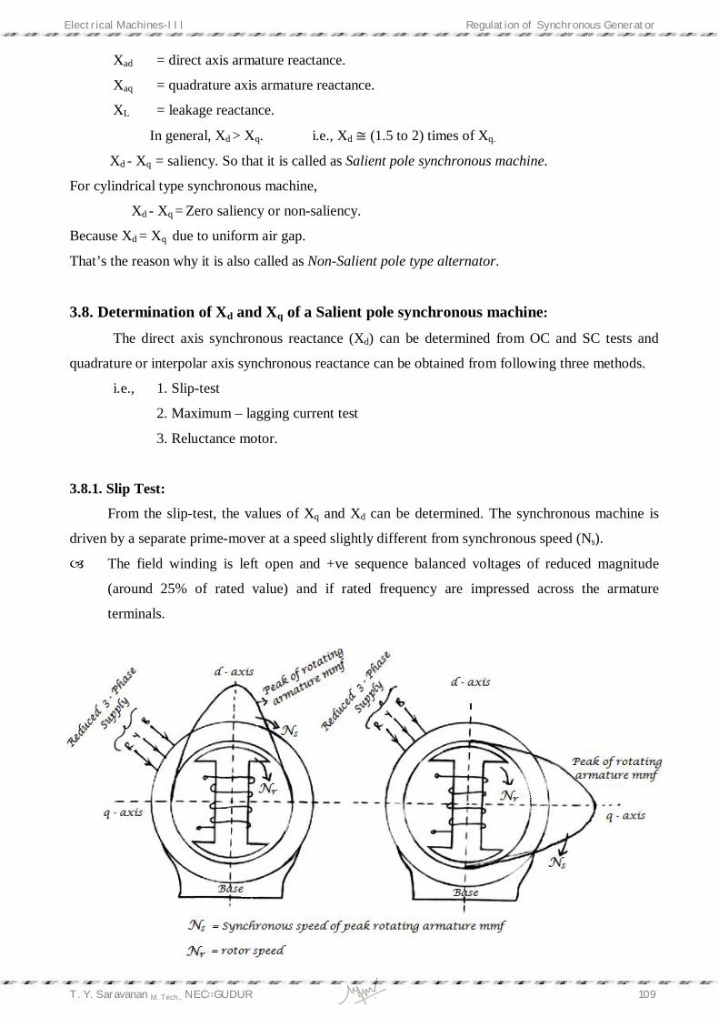
3.8.1. Slip Test:
From the slip-test, the values of Xq and Xd can be determined. The synchronous machine is
driven by a separate prime-mover at a speed slightly different from synchronous speed (Ns).
The field winding is left open and +ve sequence balanced voltages of reduced magnitude
(around 25% of rated value) and if rated frequency are impressed across the armature
terminals.
Electrical Machines-III Regulation of Synchronous Generator
T. Y. Saravanan M. Tech., NEC∷GUDUR 110
Under these conditions, the relative velocity between the field poles and the rotating armature
mmf wave is equal to the difference between synchronous speed and the rotor speed, i.e., slip
speed.
A small ac voltage across the open field winding indicates that the field poles and rotating
mmf wave is revolving in the same direction then that should be required for slip test.
If field poles revolve in a direction opposite to the rotating mmf wave –ve sequence reactance
would be measured.
At one instant, the peak of armature mmf wave is in line with the filed pole or direct axis, the
reluctance offered by the small air gap is minimum as shown in above figure. At this instant,
the terminal voltage per phase divided by the corresponding armature current per phase gives
d-axis synchronous reactance. (Xd).
Xd = Vmax
Imin because air-gap is minimum
After one – quarter (1/4) of slip cycle, the peak of armature mmf wave acts on the inter polar
or q-axis of the magnetic circuit, and reluctance offered by long air-gap is maximum. At this
instant,
Xq= Vmin
Imax because reluctance in air-gap is maximum
During this test, the induced emf in open field winding is AC Sinusoidal at Slip-frequency.
Rotating field is driven at less than Ns because when the rotor is driven at Ns, the flux linkages
are maximum, so Ia is minimum always. So we want to get maximum values of Ia i.e., field is in
locking with the stator poles.

Electrical Machines-III Regulation of Synchronous Generator
T. Y. Saravanan M. Tech., NEC∷GUDUR 111
Oscillograms of armature current and terminal voltage and the emf induced in open circuit field
winding is shown below.
When performing this test, the slip should by small as possible, otherwise the currents induced
in the magnetic circuits would cause large errors in the measurement of Xd and Xq. The
advantages of oscillographic method over Voltmeter – Ammeter method are,
i. elimination of the inertia effects of voltmeter and ammeter.
ii. the possibility of large slip-speed.
Electrical Machines-III Regulation of Synchronous Generator
T. Y. Saravanan M. Tech., NEC∷GUDUR 112
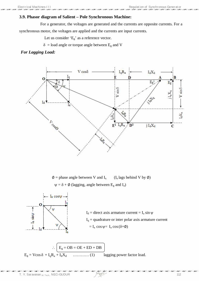
3.9. Phasor diagram of Salient – Pole Synchronous Machine: For a generator, the voltages are generated and the currents are opposite currents. For a
synchronous motor, the voltages are applied and the currents are input currents.
Let us consider ‘Eg’ as a reference vector.
δ = load angle or torque angle between Eg and V
For Lagging Load:
∅ = phase angle between V and Ia. (Ia lags behind V by ∅)
= δ + ∅ (lagging, angle between Eg and Ia)
Id = direct axis armature current = Ia sin
Iq = quadrature or inter polar axis armature current
= Ia cos= Ia cos (δ+∅)
Eg = OB = OE + ED + DB
Eg = Vcos δ + IqRa + IdXd ………… (1) lagging power factor load.
Electrical Machines-III Regulation of Synchronous Generator
T. Y. Saravanan M. Tech., NEC∷GUDUR 113
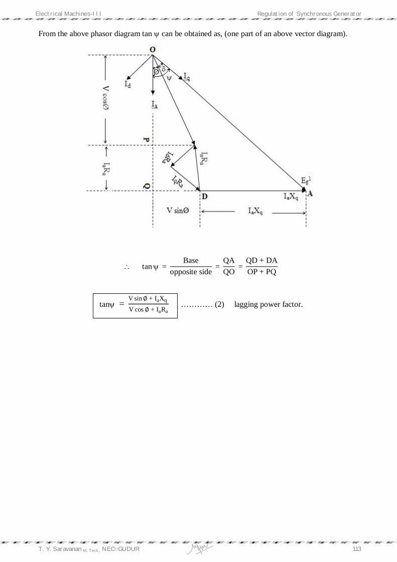
From the above phasor diagram tan can be obtained as, (one part of an above vector diagram).
tan = Base
opposite side =
QAQO
= QD + DAOP + PQ
tan = V sin∅ + IaXq
V cos∅ + IaRa ………… (2) lagging power factor.
Electrical Machines-III Regulation of Synchronous Generator
T. Y. Saravanan M. Tech., NEC∷GUDUR 114
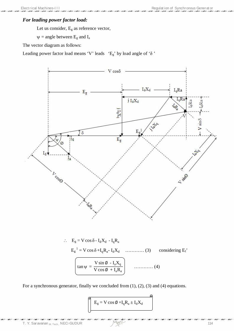
For leading power factor load: Let us consider, Eg as reference vector,
= angle between Eg and Ia
The vector diagram as follows:
Leading power factor load means ‘V’ leads ‘Eg’ by load angle of ‘δ ’
Eg = V cos δ -IdXd -IqRa
Eg 1 = V cos δ +IqRa- IdXd ………… (3) considering Ef’
tan = V sin∅ - IaXq V cos∅ + IaRa
………… (4)
For a synchronous generator, finally we concluded from (1), (2), (3) and (4) equations.
Eg = V cos∅ +IqRa ± IdXd

Electrical Machines-III Regulation of Synchronous Generator
T. Y. Saravanan M. Tech., NEC∷GUDUR 115
+ve for lagging load
-ve for leading power factor load
tan = V sin∅ ± IaXq V cos∅ + IaRa
= ∅ + δ for lagging load +ve
= ∅ - δ for leading load -ve
Thus, for the synchronous motor ‘-Ia’ is substituted for the above equations instead of ‘Ia’.
Therefore,
For salient pole synchronous motor,
Id = Ia sin
Iq = Ia cos
=∅∓δ -ve for lagging power factor load
+ve for lagging power factor load
E = V cos δ -IqRa ∓ IdXd -ve for lagging power factor load
+ve for leading power factor load
tan = V sin ∅∓ IaXq V cos∅ - IaRa
Electrical Machines-III Regulation of Synchronous Generator
T. Y. Saravanan M. Tech., NEC∷GUDUR 116
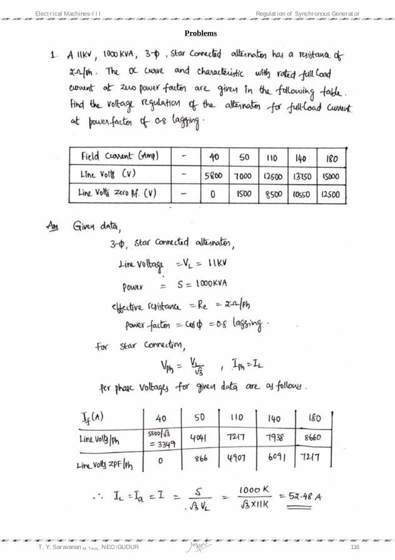
Problems

Electrical Machines-III Regulation of Synchronous Generator
T. Y. Saravanan M. Tech., NEC∷GUDUR 117

Electrical Machines-III Regulation of Synchronous Generator
T. Y. Saravanan M. Tech., NEC∷GUDUR 118

Electrical Machines-III Regulation of Synchronous Generator
T. Y. Saravanan M. Tech., NEC∷GUDUR 119
Electrical Machines-III Regulation of Synchronous Generator
T. Y. Saravanan M. Tech., NEC∷GUDUR 120
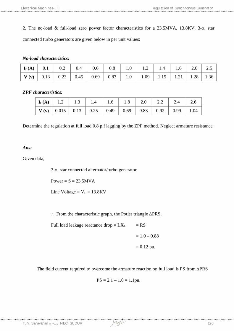
2. The no-load & full-load zero power factor characteristics for a 23.5MVA, 13.8KV, 3-, star
connected turbo generators are given below in per unit values:
No-load characteristics:
If (A) 0.1 0.2 0.4 0.6 0.8 1.0 1.2 1.4 1.6 2.0 2.5
V (v) 0.13 0.23 0.45 0.69 0.87 1.0 1.09 1.15 1.21 1.28 1.36
ZPF characteristics:
If (A) 1.2 1.3 1.4 1.6 1.8 2.0 2.2 2.4 2.6
V (v) 0.015 0.13 0.25 0.49 0.69 0.83 0.92 0.99 1.04
Determine the regulation at full load 0.8 p.f lagging by the ZPF method. Neglect armature resistance.
Ans:
Given data,
3-, star connected alternator/turbo generator
Power = S = 23.5MVA
Line Voltage = VL = 13.8KV
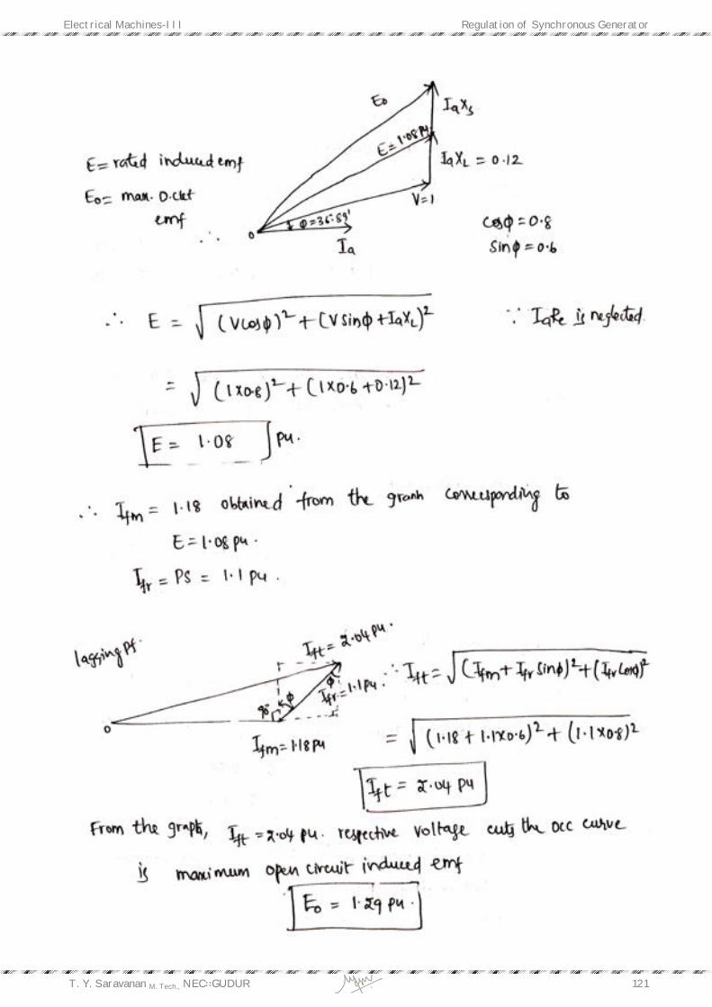
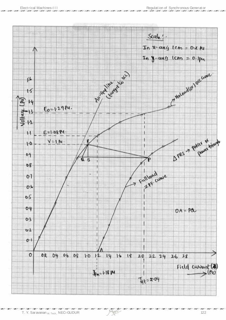
From the characteristic graph, the Potier triangle PRS,
Full load leakage reactance drop = IaXL = RS
= 1.0 – 0.88
= 0.12 pu.
The field current required to overcome the armature reaction on full load is PS from PRS
PS = 2.1 – 1.0 = 1.1pu.
Electrical Machines-III Regulation of Synchronous Generator
T. Y. Saravanan M. Tech., NEC∷GUDUR 121
Electrical Machines-III Regulation of Synchronous Generator
T. Y. Saravanan M. Tech., NEC∷GUDUR 122

Electrical Machines-III Regulation of Synchronous Generator
T. Y. Saravanan M. Tech., NEC∷GUDUR 123
Electrical Machines-III Regulation of Synchronous Generator
T. Y. Saravanan M. Tech., NEC∷GUDUR 124
Electrical Machines-III Regulation of Synchronous Generator
T. Y. Saravanan M. Tech., NEC∷GUDUR 125

Electrical Machines-III Regulation of Synchronous Generator
T. Y. Saravanan M. Tech., NEC∷GUDUR 126
Electrical Machines-III Regulation of Synchronous Generator
T. Y. Saravanan M. Tech., NEC∷GUDUR 127
Electrical Machines-III Regulation of Synchronous Generator
T. Y. Saravanan M. Tech., NEC∷GUDUR 128
Electrical Machines-III Regulation of Synchronous Generator
T. Y. Saravanan M. Tech., NEC∷GUDUR 129
Electrical Machines-III Regulation of Synchronous Generator
T. Y. Saravanan M. Tech., NEC∷GUDUR 130
Electrical Machines-III Regulation of Synchronous Generator
T. Y. Saravanan M. Tech., NEC∷GUDUR 131
Electrical Machines-III Regulation of Synchronous Generator
T. Y. Saravanan M. Tech., NEC∷GUDUR 132
Electrical Machines-III Regulation of Synchronous Generator
T. Y. Saravanan M. Tech., NEC∷GUDUR 133
Electrical Machines-III Regulation of Synchronous Generator
T. Y. Saravanan M. Tech., NEC∷GUDUR 134
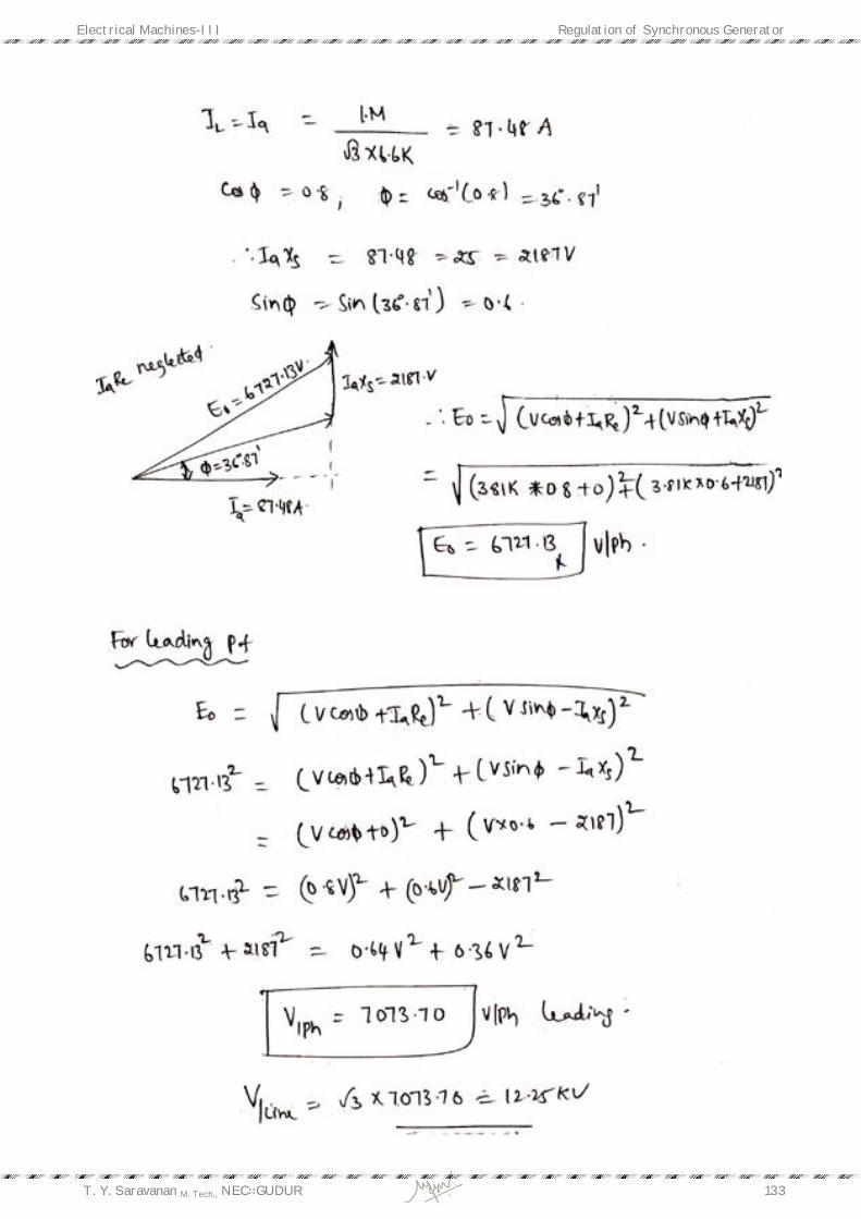
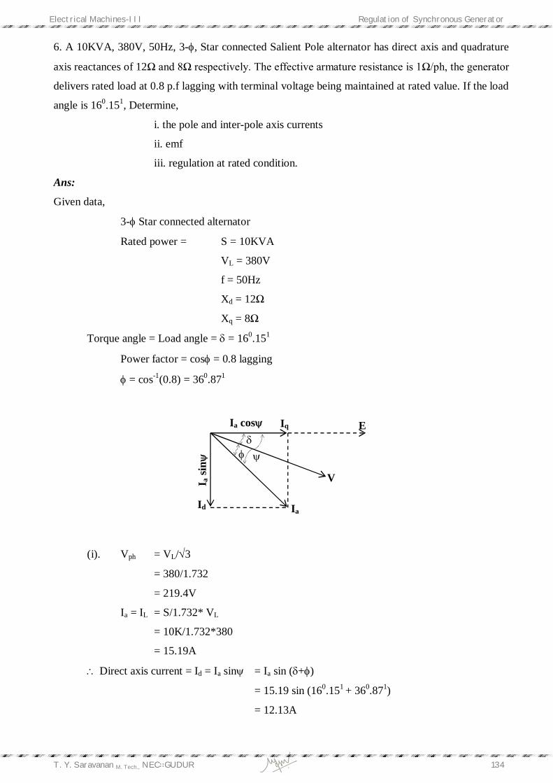
6. A 10KVA, 380V, 50Hz, 3-, Star connected Salient Pole alternator has direct axis and quadrature
axis reactances of 12Ω and 8Ω respectively. The effective armature resistance is 1Ω/ph, the generator
delivers rated load at 0.8 p.f lagging with terminal voltage being maintained at rated value. If the load
angle is 160.151, Determine,
i. the pole and inter-pole axis currents
ii. emf
iii. regulation at rated condition.
Ans:
Given data,
3- Star connected alternator
Rated power = S = 10KVA
VL = 380V
f = 50Hz
Xd = 12Ω
Xq = 8Ω
Torque angle = Load angle = = 160.151
Power factor = cos = 0.8 lagging
= cos-1(0.8) = 360.871
(i). Vph = VL/3
= 380/1.732
= 219.4V
Ia = IL = S/1.732* VL
= 10K/1.732*380
= 15.19A
Direct axis current = Id = Ia sin = Ia sin (+)
= 15.19 sin (160.151 + 360.871)
= 12.13A
I a si
n
Ia cos Iq
Id Ia
V
E
Electrical Machines-III Regulation of Synchronous Generator
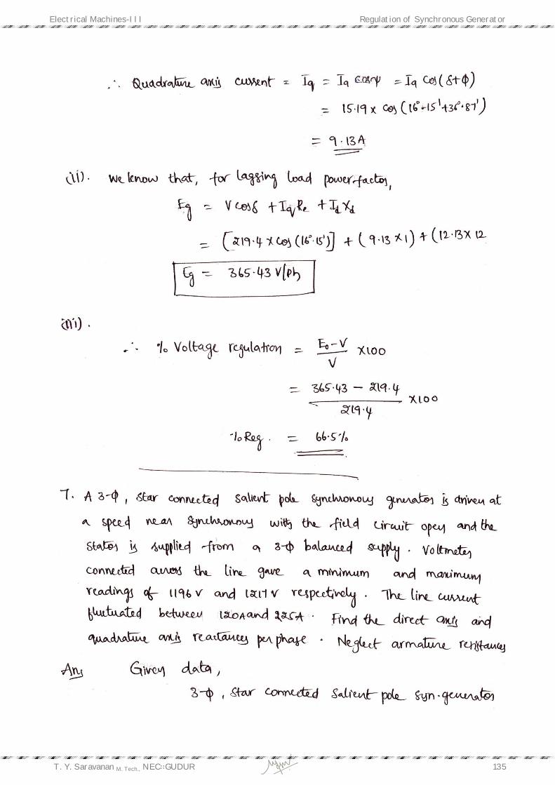
T. Y. Saravanan M. Tech., NEC∷GUDUR 135
Electrical Machines-III Regulation of Synchronous Generator
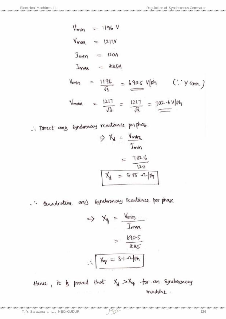
T. Y. Saravanan M. Tech., NEC∷GUDUR 136
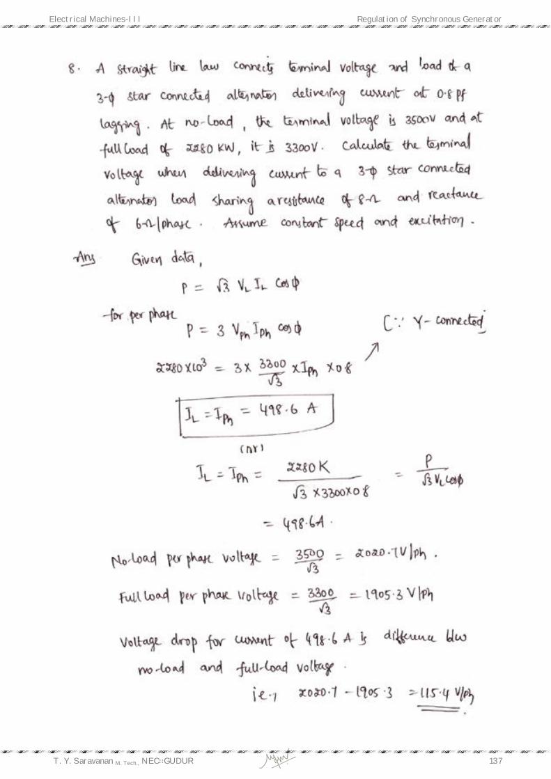
Electrical Machines-III Regulation of Synchronous Generator
T. Y. Saravanan M. Tech., NEC∷GUDUR 137
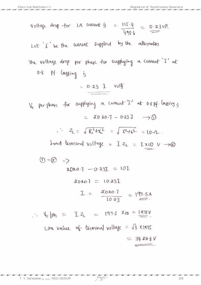
Electrical Machines-III Regulation of Synchronous Generator
T. Y. Saravanan M. Tech., NEC∷GUDUR 138
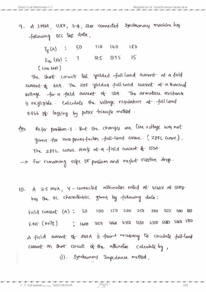
Electrical Machines-III Regulation of Synchronous Generator
T. Y. Saravanan M. Tech., NEC∷GUDUR 139
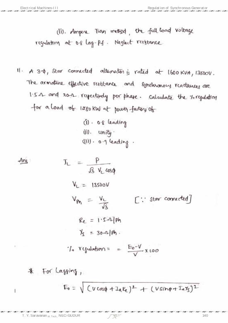
Electrical Machines-III Regulation of Synchronous Generator
T. Y. Saravanan M. Tech., NEC∷GUDUR 140
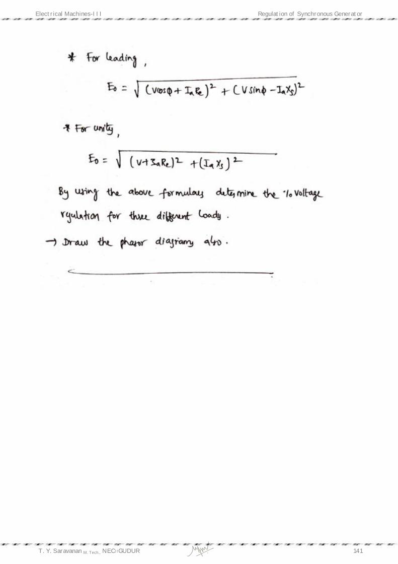
Electrical Machines-III Regulation of Synchronous Generator
T. Y. Saravanan M. Tech., NEC∷GUDUR 141
Electrical Machines-III Regulation of Synchronous Generator
T. Y. Saravanan M. Tech., NEC∷GUDUR 142
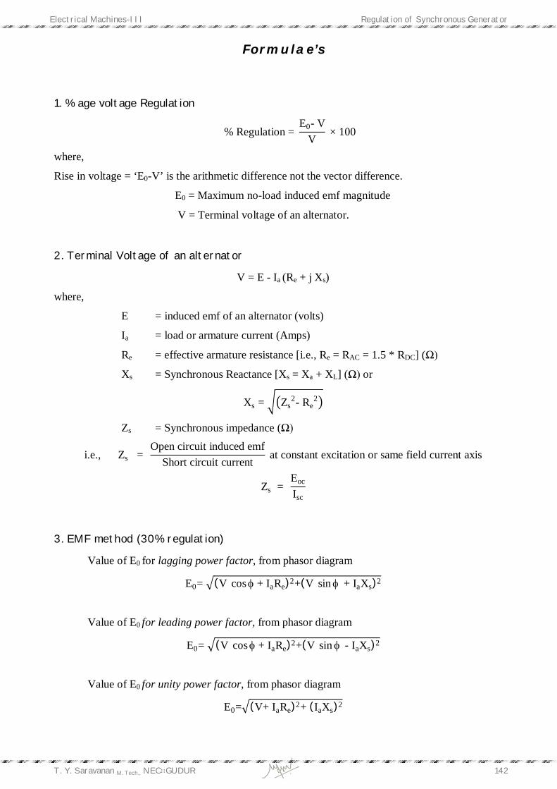
Formulae’s
1. % age voltage Regulation
% Regulation = E0- V
V × 100
where,
Rise in voltage = ‘E0-V’ is the arithmetic difference not the vector difference.
E0 = Maximum no-load induced emf magnitude
V = Terminal voltage of an alternator.
2. Terminal Voltage of an alternator
V = E - Ia (Re + j Xs)
where,
E = induced emf of an alternator (volts)
Ia = load or armature current (Amps)
Re = effective armature resistance [i.e., Re = RAC = 1.5 * RDC] (Ω)
Xs = Synchronous Reactance [Xs = Xa + XL] (Ω) or
Xs = Zs2- Re
2
Zs = Synchronous impedance (Ω)
i.e., Zs = Open circuit induced emf
Short circuit current at constant excitation or same field current axis
Zs = Eoc
Isc
3. EMF method (30% regulation)
Value of E0 for lagging power factor, from phasor diagram
E0= (V cos + IaRe)2+(V sin + IaXs)2
Value of E0 for leading power factor, from phasor diagram
E0= (V cos + IaRe)2+(V sin - IaXs)2
Value of E0 for unity power factor, from phasor diagram
E0= (V+ IaRe)2+ (IaXs)2

Electrical Machines-III Regulation of Synchronous Generator
T. Y. Saravanan M. Tech., NEC∷GUDUR 143
4. MMF method (15% regulation)
Value of Ift for lagging power factor, from phasor diagram (Ift angle 900 + )
Ift= (Ifm+ Ifr sin )2+ (Ifr cos)2
Value of Ift for leading power factor, from phasor diagram (Ift angle 900 - )
Ift= (Ifm- Ifr sin )2+ (Ifr cos)2
Value of Ift for unity power factor, from phasor diagram (Ift angle 900)
Ift= (Ifm)2+ (Ifr)2
Where,
Ifm = field current at rated induced emf (E)
Ifr = field current at rated or Full Load or short circuit current (Irated or IFL or Isc)
Ift = field current at maximum open circuit induced emf (E0)
5. ZPF method (20% regulation)
Value of Ift for lagging power factor, from phasor diagram (Ift angle 900 + )
Ift= (Ifm+ Ifr sin )2+ (Ifr cos)2
Value of Ift for leading power factor, from phasor diagram (Ift angle 900 - )
Ift= (Ifm- Ifr sin )2+ (Ifr cos)2
Value of Ift for unity power factor, from phasor diagram (Ift angle 900)
Ift= (Ifm)2+ (Ifr)2
Where,
Ifm = field current at rated induced emf (E)
Ifr = field current at rated or Full Load or short circuit current (Irated or IFL or Isc)
Ift = field current at maximum open circuit induced emf (E0)
PRS = Potier triangle
RS = IaXL drop
E = V + Ia (Re + j XL) = rated induced emf
E0 = V + Ia [Re + j (XL+ Xa)] = maximum open circuit induced emf
Angle between Ifm and E is 900
Angle between Ift and E0 is 900

Electrical Machines-III Regulation of Synchronous Generator
T. Y. Saravanan M. Tech., NEC∷GUDUR 144
6. ASA method (25% regulation)
All calculations same as ZPF method but saturation of current is considered .
Ift
1 = field current at maximum open circuit induced emf (E0) when saturation considered.
7. from two reaction analysis
Xd = Xad + XL
Xq = Xaq + XL
Xd = direct or pole axis reactance (Ω)
Xq = quadrature or interpole axis reactance (Ω)
XL = Leakage reactance (Ω)
Xad = direct or pole axis armature reactance (Ω)
Xaq = quadrature or interpole axis armature reactance (Ω)
8. from slip test
Xd = Vmax
Imin because air-gap is minimum
Xq= Vmin
Imax because reluctance in air-gap is maximum
i.e., Air-Gap Length ∝ 1
armature reaction ∝
1Xa
9. from Salient pole alternator
Eg = V cos∅ +IqRa ± IdXd
+ve for lagging load
-ve for leading power factor load
Electrical Machines-III Regulation of Synchronous Generator
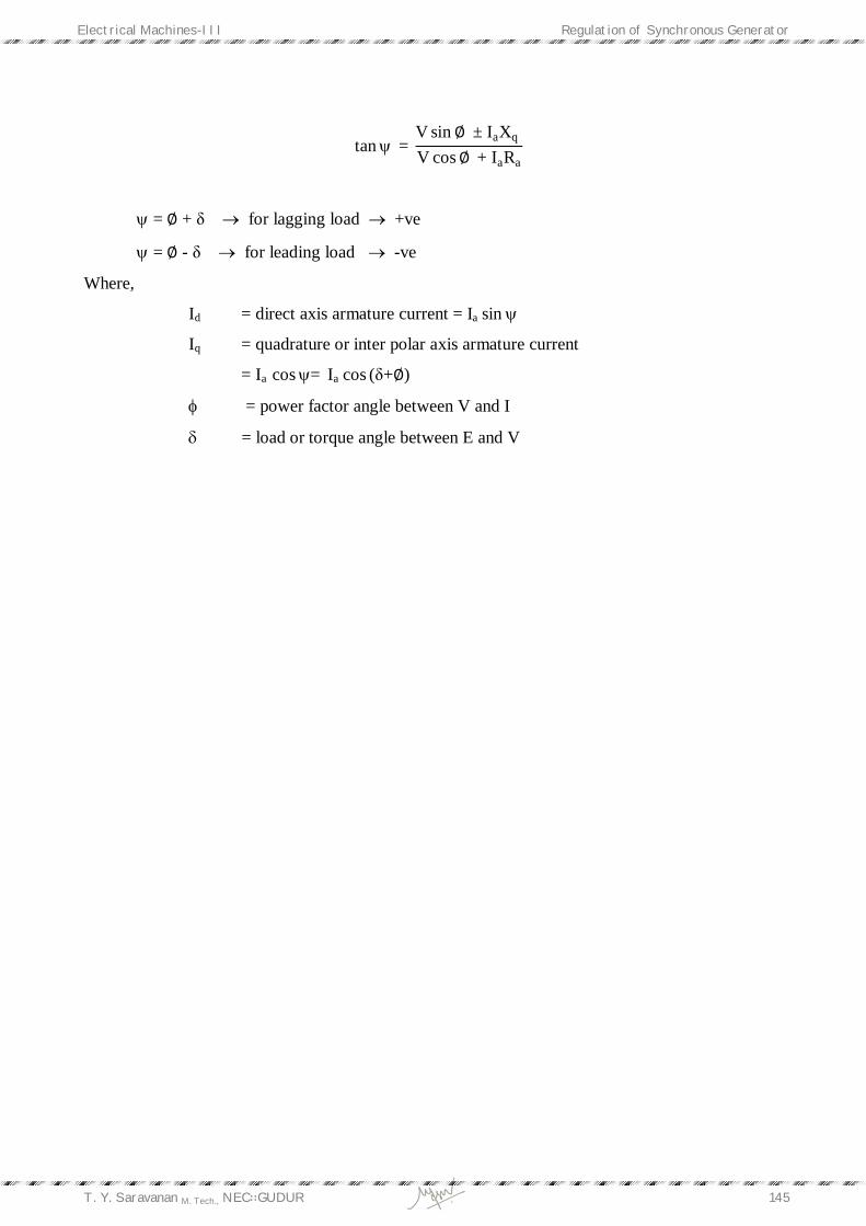
T. Y. Saravanan M. Tech., NEC∷GUDUR 145
tan = V sin∅ ± IaXq V cos∅ + IaRa
= ∅ + δ for lagging load +ve
= ∅ - δ for leading load -ve
Where,
Id = direct axis armature current = Ia sin
Iq = quadrature or inter polar axis armature current
= Ia cos= Ia cos (δ+∅)
= power factor angle between V and I
= load or torque angle between E and V

Filename: UNIT - 3 2013-14 Directory: E:\Notes\EM-III Notes\Print\U-3 Template:
C:\Users\sravana\AppData\Roaming\Microsoft\Templates\Normal.dotm
Title: Subject: Author: sravana Keywords: Comments: Creation Date: 05-Aug-13 9:05:00 AM Change Number: 1,885 Last Saved On: 16-Oct-13 10:08:00 AM Last Saved By: JNTU Total Editing Time: 767 Minutes Last Printed On: 16-Oct-13 10:11:00 AM As of Last Complete Printing Number of Pages: 54 Number of Words: 5,022 (approx.) Number of Characters: 28,632 (approx.)