registers - dld · universal shift register if the register has both shifts and parallel load...
TRANSCRIPT

Registers
By : Ali Mustafa

Registers & Counter
• Circuits that include flip-flops are usually classified by the function they perform– Registers– Counters
• Register is a group of flip-flops.– Each flip-flop is capable of storing one bit of
information.– An n-bit register consists of a group of n flip-flops.– Register is a group of binary cells suitable for holding
binary information.
• A counter is essentially a register that goes through a predetermined sequence of states.

4-Bit Register
• A simple 4-bit register can be made with 4 D-FF• Data is loaded in parallel
• Common Clock• At each positive-edge, 4 bits are loaded
in parallel• Previous data is overwritten• Entering data is called loading
• Common Clear• Asynchronous active-low clear• When Clear = 0, all FFs are cleared; i.e.
0 is stored.
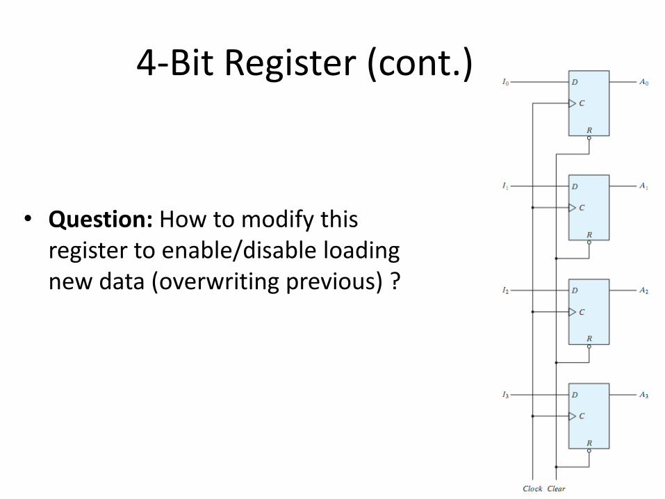
4-Bit Register (cont.)
• Question: How to modify this register to enable/disable loading new data (overwriting previous) ?

4-Bit Register (cont.)
• Question: How to modify this register to enable/disable loading new data (overwriting previous) ?
• Answer: When Load=0, the clock input to the FFs will never take a transition (0 to 1, 1 to 0), no new data will be loaded. When Load=1, normal data loading takes place
• This is called clock gating

4-Bit Register (cont.)
• Clock Skew Problem:
• It results from clock gating.
4-Bit Register (cont.)
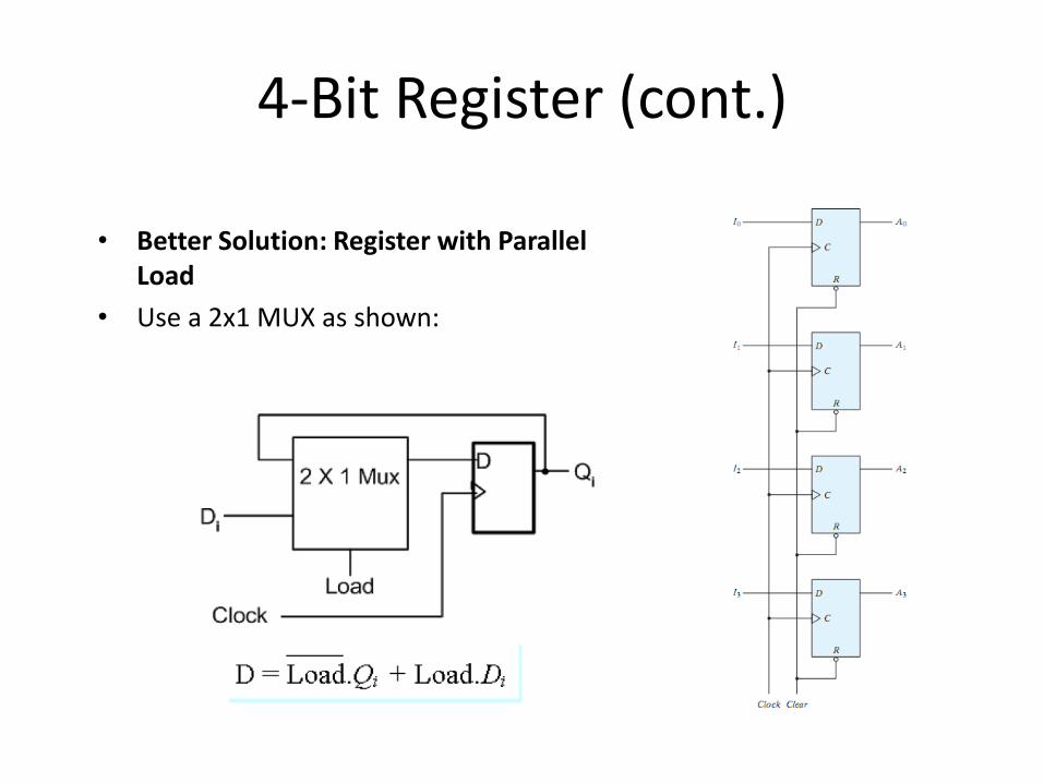
• Better Solution: Register with Parallel Load
• Use a 2x1 MUX as shown:

4-Bit Register (cont.)
clockload
• A 4-bit Parallel Load Register
• When Load = 0, the data is not changed (no loading)
• When Load = 1, the data is loaded in parallel at the rising edge (+ve)

Register with Parallel Load
• Synchronous digital systems have a master clock generator that supplies a continuous train of clock pulses.
• The transfer of new information into a register is referred to as loading the register.
• If all the bits of the register are loaded simultaneously with a common clock pulse, we say that the loading is done in parallel.
• The load input determines whether the next pulse will accept new information or leave the information in the register intact

Register with Parallel Load• Load = 1 ; the I inputs
are transferred into the register
• Load = 0 ; maintain the content of the register
• Because the D flip-flop does not have a “no change”

Register with Parallel Load

Shift Registers
• Capable of shifting its binary information in one or both directions

Shift Register Applications• Shift Registers are an important Flip-Flop configuration
with a wide range of applications, including:
– Computer and Data Communications
– Serial and Parallel Communications
– Multi-bit number storage
– Sequencing
– Basic arithmetic such as scaling (a serial shift to the left or right will change the value of a binary number a power of 2)
– Logical operations

Parallel versus Serial• Serial communications: provides a binary number as a
sequence of binary digits, one after another, through one data line.
• Parallel communications: provides a binary number as binary digits through multiple data lines at the same time.

Shift Registers
• Shift Registers are devices that store and move data bits in serial (to the left or the right),
• ..or in parallel,
• ..or a combination of serial and parallel.

Configuration
• In Shift Registers, the binary digit transfers (shifts) from the output of one flip-flop to the input of the next individual Flip-Flop at every clock edge.
• Once the binary digits are shifted in, the individual Flip-Flops will each retain a bit, and the whole configuration will retain a binary number.
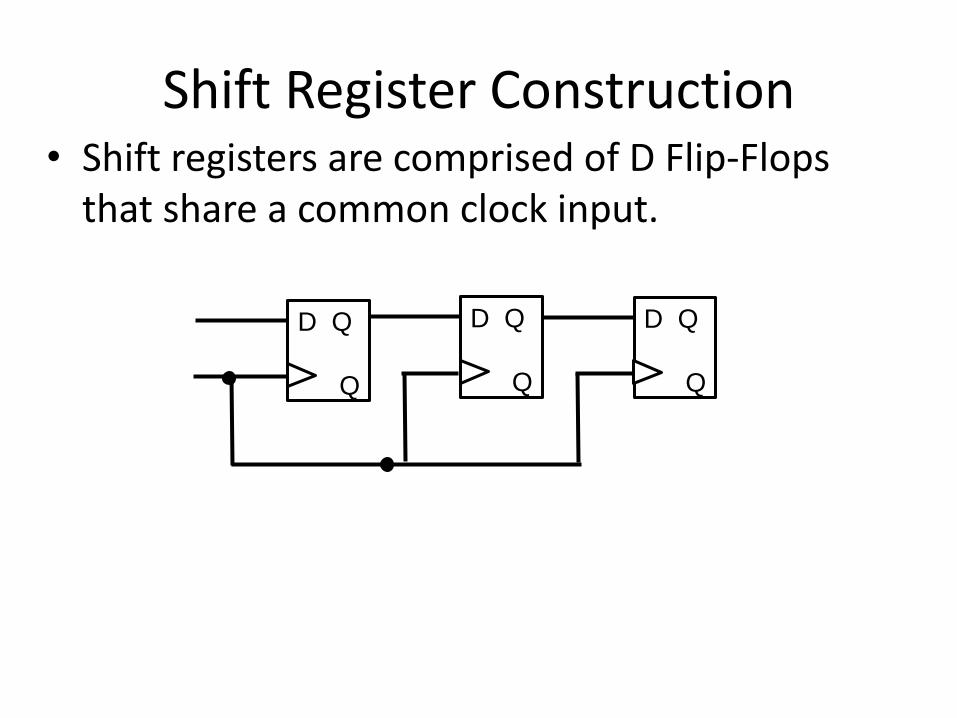
Shift Register Construction• Shift registers are comprised of D Flip-Flops
that share a common clock input.
D Q
Q
D Q
Q
D Q
Q
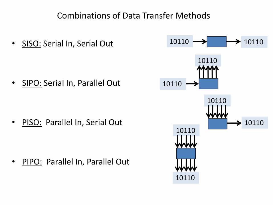
Combinations of Data Transfer Methods
• SISO: Serial In, Serial Out
• SIPO: Serial In, Parallel Out
• PISO: Parallel In, Serial Out
• PIPO: Parallel In, Parallel Out
10110 10110
10110
10110
10110
1011010110
10110

SISO Flip-Flop Shift Register
• Serial In Serial Out shift register has a single input and a single output
D Q
Q
D Q
Q
D Q
Q
Input Output

SIPO Flip-Flop Shift Register• Serial In Parallel Out shift register has a single
input and access to all outputs
D Q
Q
D Q
Q
D Q
Q
Input
Output Output Output
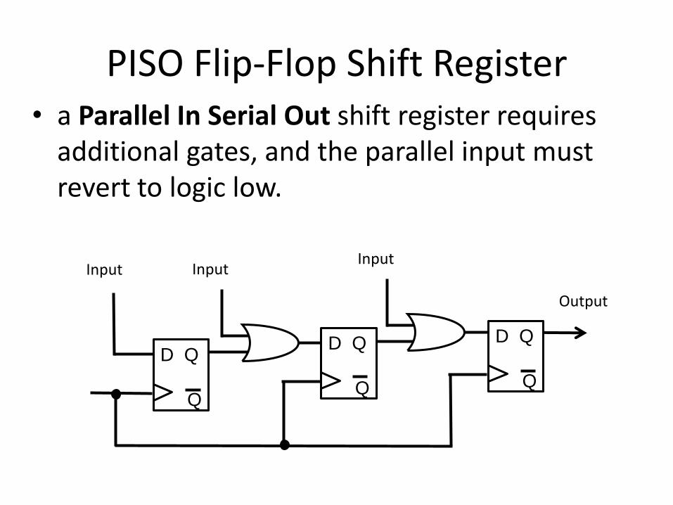
PISO Flip-Flop Shift Register• a Parallel In Serial Out shift register requires
additional gates, and the parallel input must revert to logic low.
Input
D Q
Q
Input
Output
Input
D Q
Q
D Q
Q
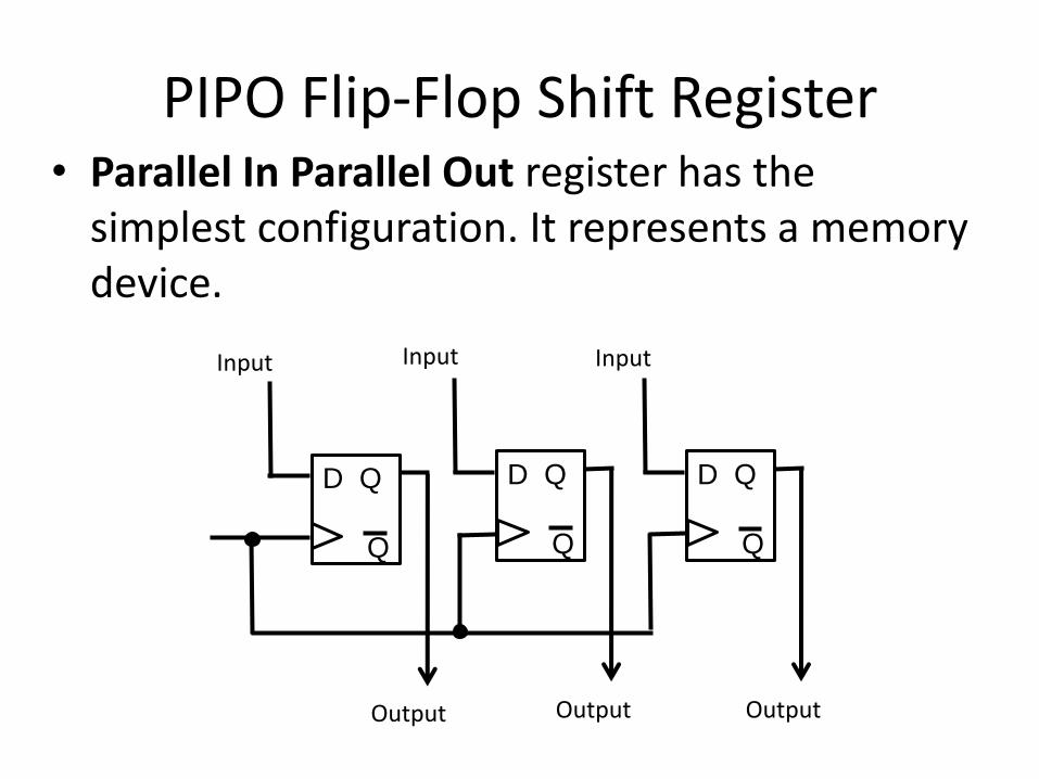
PIPO Flip-Flop Shift Register• Parallel In Parallel Out register has the
simplest configuration. It represents a memory device.
D Q
Q
Input
Output
D Q
Q
Output
D Q
Q
Output
Input Input

Shift Registers: Serial Transfer

Shift Register A Shift Register BS0 S1S1 S0
CLK

Example: Serial Transfer

Universal Shift Register
If the register has both shifts and parallel load capabilities, it is referred to as a universal shift register.
• A clear control to clear the register to 0.• A clock input to synchronize the operations.• A shift-right control to enable the shift right operation and
the serial input and output lines associated with the shift right.
• A shift-left control to enable the shift left operation and the serial input and output lines associated with the shift left.
• A parallel-load control to enable a parallel transfer and the n input lines associated with the parallel transfer.
• n parallel output lines• A control state that leaves the information in the register
unchanged in the presence of the clock.

Universal Shift Register

Universal Shift Register (cont.)
Universal Shift Register (cont.)
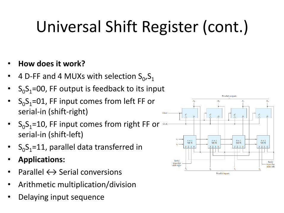
• How does it work?
• 4 D-FF and 4 MUXs with selection S0,S1
• S0S1=00, FF output is feedback to its input
• S0S1=01, FF input comes from left FF or serial-in (shift-right)
• S0S1=10, FF input comes from right FF or serial-in (shift-left)
• S0S1=11, parallel data transferred in
• Applications:
• Parallel ↔ Serial conversions
• Arithmetic multiplication/division
• Delaying input sequence

Counters• Counter: A register (sequential circuit) that goes through a pre-
determined sequence of states upon the application of input (clock or other source) pulses
• Binary Counter: The sequence of the states follows the binary number sequence (e.g. 000 001 010 011 etc.)• n-bit binary counter requires n flip-flops – counts from 0 to 2n-1
• Sequences can be binary, BCD, random, etc. • Counting can be up, down• A modulo-n counter goes through values 0,1,2, …, (n-1)
• e.g. modulo-10 up counter counts: 0,1,…9
• Two Types of Counters:
• Ripple counter (asynchronous):• Flip-flop output transition serves as source for triggering the other flip-
flops
• Synchronous counter:• common clock for all flip-flops (same design procedure)