regenerative drying systems - gosuburban.com dryer installation instructions.pdf · • the plc...
TRANSCRIPT

Suburban Manufacturing, Inc. 10531 Dalton Ave NE Monticello, MN 55362 USA
(800)782-5752 fax (763) 295-6601 12
a division of: Suburban Manufacturing, Inc. Monticello, MN 55362 1-800-782-5752
764-2064
Take your compressed air system into the future with the newest regenerative
drying system.
REGENERATIVE DRYING
SYSTEMS
User Manual Installation Instructions
!! Please Retain This Manual for Your Records !!
Tsunami Compressed Air Solutions is a division of

**IMPORTANT**
There is a MANDATORY 6 month maintenance schedule for the Oil coalescing pre-filter, P/N 21999-0202-Z-SP
There is a MANDATORY 1 year maintenance schedule for the
lubrication of the piston spool and piston bore.
Failure to follow all maintenance schedules will void all warranties
**It is MANDATORY to install a bypass circuit around the dryer for maintenance purposes**
— use appropriate thread sealant on all fittings unless otherwise specified —
YOUR SAFETY IS IMPORTANT
Read ALL instructions before you begin the installation of your Tsunami Regenerative Drying System
Observe and follow all caution and warning instructions
!!CAUTION!!
**SYSTEM PRESSURE MUST BE RELEASED PRIOR TO INSTALLING DRYER**
• Tsunami Regenerative Drying Systems should be installed with a bypass circuit to allow for proper maintenance of unit
• Always wear eye protection when working on Tsunami Regenerative Drying Systems
• Use only proper tools and follow all precautions which pertain to the use of those tools
• Use appropriate thread sealant on all fittings unless otherwise specified
2
Maintenance Schedule for All Tsunami Regenerative Dryer Systems
P/N 21999-0202-Z-SP Oil Coalescing Replacement Element
Every 6 months: (Mandatory)
• Replace the oil coalescing element
3-5 year Maintenance Program: (Strongly Recommended)
• Replace piston spool valve - one per tower
P/N 21999-0707
• Replace molecular sieve canisters (towers)
P/N 21999-0349
• Perform 6 month maintenance requirement
P/N 21999-0202-Z-SP
**SYSTEM PRESSURE MUST BE RELEASED PRIOR TO PERFORMING MAINTENANCE PROCEDURES**
Replacing the oil coalescing pre-filter element
Step 1: Open ball valve on bottom filter housing to release any system pressure
Step 3: Remove the bottom nut and replace element
Step 4: Screw housing onto filter head and attach drain line. Be sure to close ball valve on the bottom of the filter
11
P/N 21999-0349 Tower Replacement
P/N 21999-0707 Piston Rebuild Kit
Step 2: Remove drain line and unscrew the filter housing
Once per year : (Mandatory)
• Lubricate the piston spool and piston bore
using the grease provided in the replacement element kit.

Programmable Logic Controller
10
Installation procedures for 50Hp Tsunami Stand Alone Drying System
Step 1:
Connect inlet air supply to 1½” NPT port
Step 2:
Connect outlet air supply to 1½” NPT port
Step 3:
Make sure the wall pack adaptor is connected to the PLC control box. Be sure to snug up the locking nut on the plug end. Plug wall pack into outlet.
International installations outside of North America must choose the correct prong adaptor for their region prior to plugging into power outlet. (see Page 8, Step 10b)
• The PLC used on the Tsunami Regenerative Dryer is pre-programmed and should automatically jump into the run mode once the unit is plugged in to your power supply.
• There are 3 basic display screens: Run Mode, Stop Mode, and Warning mode. The warning mode tells you that it is time to perform your mandatory maintenance on the oil coalescing pre-filter of the dryer
RUN MODE
NORMAL OPERATING CONDITION
• RUN is displayed on the screen
• The little icons on the bottom of
the display move in a rotating manner
STOP MODE
PLC needs to be manually shifted to run mode (see below)
• STOP is displayed on the screen
• The little icons on the bottom of the
display have stopped rotating
How to get your PLC into the RUN Mode
Step 1:
Press the Menu/OK button to bring up the menu screen.
Step 2: • Press the down arrow to highlight
Run/Stop
• Press the Menu/OK button to
enter selection
WARNING MODE
Mandatory maintenance is due on the oil coalescing element
• To reset, press and hold in both the left and right arrow
buttons for approx. 10 seconds
Step 3: • Hit the down button until you highlight
“NO NONVOLAT INI”
• Press Menu/OK button to enter selection
Step 4: • PLC should now display the
RUN MODE on screen
Congratulations on your purchase of the Tsunami
Regenerative Drying System. We are very pleased
that you have decided to use the latest technology
to improve your compressed air system.
Your air system, using regenerative drying
technology, will provide years of service with
little maintenance required.
Thank You.
TABLE OF CONTENTS GGGGGGGPage 2 GGGGGGGPage 3 GGGGGGGPage 4 GGGGGGGPage 5 GGGGGGGPages 6-8 GGGGGGGPage 9 GGGGGGGPage 10 GGGGGGGPage 10 GGGGGGGPage 11
Safety Precautions GGGGG. Table of Contents GGGGG.. Technical Description GGGG Installation Guidelines GGGG Wall Mount Installation GGG.. Ultra System Installation GG... Stand Alone Dryer Installation .. Programmable Logic Controller Maintenance Guide GGGGG
3
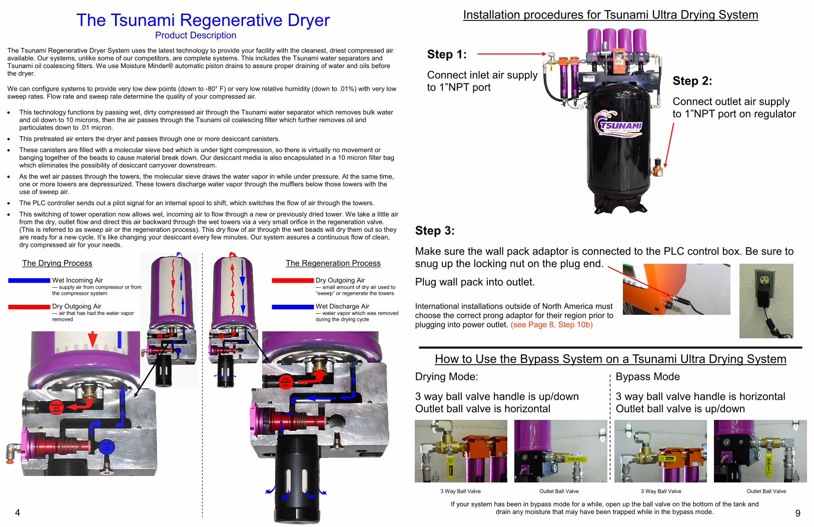
The Tsunami Regenerative Dryer Product Description
The Tsunami Regenerative Dryer System uses the latest technology to provide your facility with the cleanest, driest compressed air available. Our systems, unlike some of our competitors, are complete systems. This includes the Tsunami water separators and Tsunami oil coalescing filters. We use Moisture Minder® automatic piston drains to assure proper draining of water and oils before the dryer. We can configure systems to provide very low dew points (down to -80° F) or very low relative humidity (down to .01%) with very low sweep rates. Flow rate and sweep rate determine the quality of your compressed air.
• This technology functions by passing wet, dirty compressed air through the Tsunami water separator which removes bulk water and oil down to 10 microns, then the air passes through the Tsunami oil coalescing filter which further removes oil and particulates down to .01 micron.
• This pretreated air enters the dryer and passes through one or more desiccant canisters.
• These canisters are filled with a molecular sieve bed which is under tight compression, so there is virtually no movement or banging together of the beads to cause material break down. Our desiccant media is also encapsulated in a 10 micron filter bag which eliminates the possibility of desiccant carryover downstream.
• As the wet air passes through the towers, the molecular sieve draws the water vapor in while under pressure. At the same time, one or more towers are depressurized. These towers discharge water vapor through the mufflers below those towers with the use of sweep air.
• The PLC controller sends out a pilot signal for an internal spool to shift, which switches the flow of air through the towers.
• This switching of tower operation now allows wet, incoming air to flow through a new or previously dried tower. We take a little air from the dry, outlet flow and direct this air backward through the wet towers via a very small orifice in the regeneration valve. (This is referred to as sweep air or the regeneration process). This dry flow of air through the wet beads will dry them out so they are ready for a new cycle. It’s like changing your desiccant every few minutes. Our system assures a continuous flow of clean, dry compressed air for your needs.
The Drying Process The Regeneration Process
Wet Incoming Air — supply air from compressor or from the compressor system
Dry Outgoing Air — air that has had the water vapor removed
Dry Outgoing Air — small amount of dry air used to “sweep” or regenerate the towers
Wet Discharge Air — water vapor which was removed during the drying cycle
4
Installation procedures for Tsunami Ultra Drying System
Step 1:
Connect inlet air supply to 1”NPT port
Step 2:
Connect outlet air supply to 1”NPT port on regulator
Step 3:
Make sure the wall pack adaptor is connected to the PLC control box. Be sure to snug up the locking nut on the plug end.
Plug wall pack into outlet.
How to Use the Bypass System on a Tsunami Ultra Drying System
Drying Mode:
3 way ball valve handle is up/down Outlet ball valve is horizontal
Bypass Mode
3 way ball valve handle is horizontal Outlet ball valve is up/down
3 Way Ball Valve Outlet Ball Valve 3 Way Ball Valve Outlet Ball Valve
If your system has been in bypass mode for a while, open up the ball valve on the bottom of the tank and drain any moisture that may have been trapped while in the bypass mode. 9
International installations outside of North America must choose the correct prong adaptor for their region prior to plugging into power outlet. (see Page 8, Step 10b)
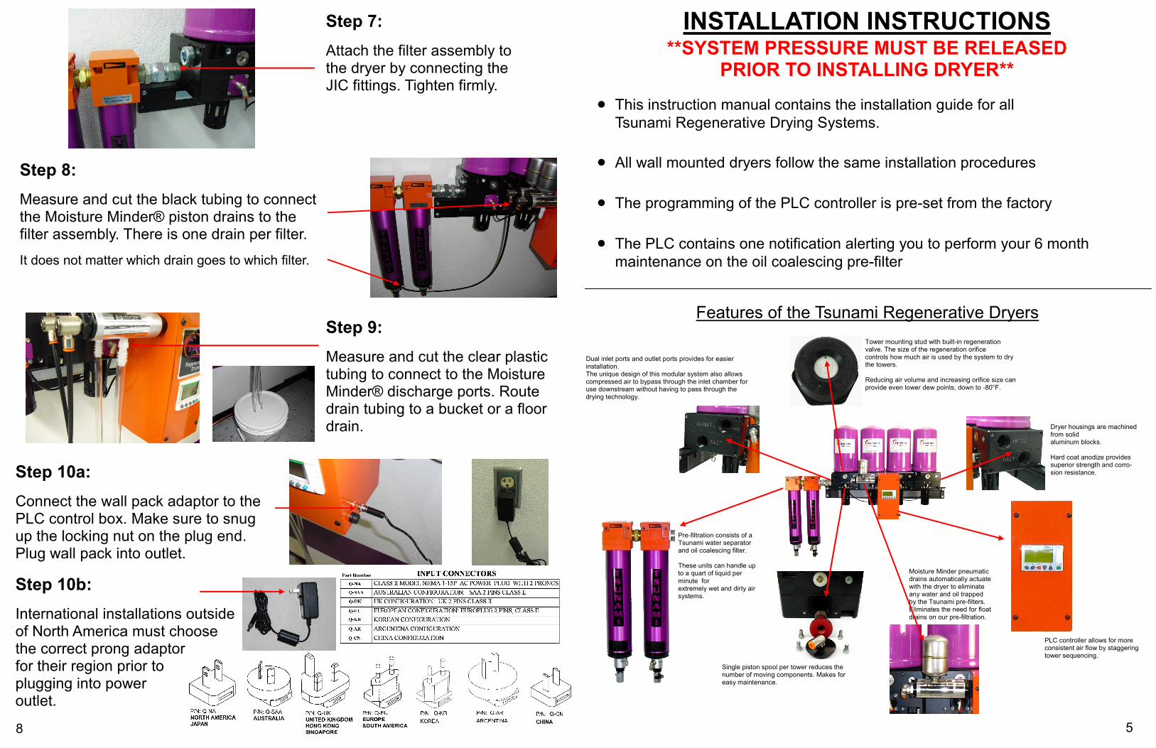
Step 9:
Measure and cut the clear plastic tubing to connect to the Moisture Minder® discharge ports. Route drain tubing to a bucket or a floor drain.
Step 8:
Measure and cut the black tubing to connect the Moisture Minder® piston drains to the filter assembly. There is one drain per filter.
It does not matter which drain goes to which filter.
Step 7:
Attach the filter assembly to the dryer by connecting the JIC fittings. Tighten firmly.
Step 10a:
Connect the wall pack adaptor to the PLC control box. Make sure to snug up the locking nut on the plug end. Plug wall pack into outlet.
8
Step 10b:
International installations outside of North America must choose the correct prong adaptor for their region prior to plugging into power outlet.
INSTALLATION INSTRUCTIONS **SYSTEM PRESSURE MUST BE RELEASED
PRIOR TO INSTALLING DRYER**
• This instruction manual contains the installation guide for all
Tsunami Regenerative Drying Systems.
• All wall mounted dryers follow the same installation procedures
• The programming of the PLC controller is pre-set from the factory
• The PLC contains one notification alerting you to perform your 6 month
maintenance on the oil coalescing pre-filter
Dryer housings are machined from solid aluminum blocks. Hard coat anodize provides superior strength and corro-sion resistance.
Single piston spool per tower reduces the number of moving components. Makes for easy maintenance.
Pre-filtration consists of a Tsunami water separator and oil coalescing filter. These units can handle up to a quart of liquid per minute for extremely wet and dirty air systems.
Moisture Minder pneumatic drains automatically actuate with the dryer to eliminate any water and oil trapped by the Tsunami pre-filters. Eliminates the need for float drains on our pre-filtration.
Dual inlet ports and outlet ports provides for easier installation. The unique design of this modular system also allows compressed air to bypass through the inlet chamber for use downstream without having to pass through the drying technology.
Tower mounting stud with built-in regeneration valve. The size of the regeneration orifice controls how much air is used by the system to dry the towers. Reducing air volume and increasing orifice size can provide even lower dew points; down to -80°F.
PLC controller allows for more consistent air flow by staggering tower sequencing.
Features of the Tsunami Regenerative Dryers
5
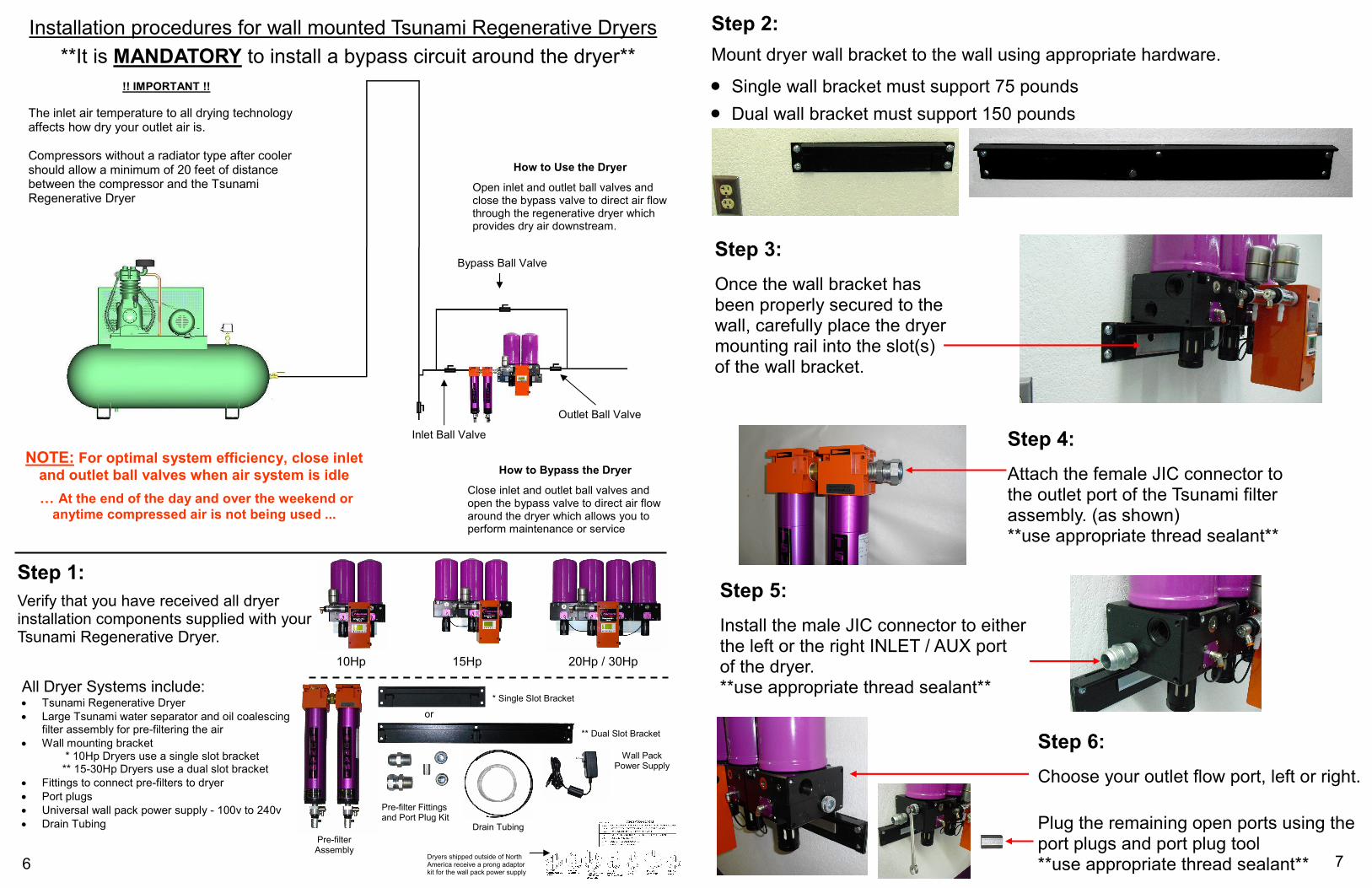
Step 1:
Verify that you have received all dryer installation components supplied with your Tsunami Regenerative Dryer.
**It is MANDATORY to install a bypass circuit around the dryer**
!! IMPORTANT !!
The inlet air temperature to all drying technology affects how dry your outlet air is. Compressors without a radiator type after cooler should allow a minimum of 20 feet of distance between the compressor and the Tsunami Regenerative Dryer
NOTE: For optimal system efficiency, close inlet
and outlet ball valves when air system is idle
> At the end of the day and over the weekend or anytime compressed air is not being used ...
Inlet Ball Valve
Outlet Ball Valve
Bypass Ball Valve
Close inlet and outlet ball valves and open the bypass valve to direct air flow around the dryer which allows you to perform maintenance or service
How to Bypass the Dryer
Open inlet and outlet ball valves and close the bypass valve to direct air flow through the regenerative dryer which provides dry air downstream.
How to Use the Dryer
Installation procedures for wall mounted Tsunami Regenerative Dryers
All Dryer Systems include:
• Tsunami Regenerative Dryer
• Large Tsunami water separator and oil coalescing filter assembly for pre-filtering the air
• Wall mounting bracket
* 10Hp Dryers use a single slot bracket ** 15-30Hp Dryers use a dual slot bracket
• Fittings to connect pre-filters to dryer
• Port plugs
• Universal wall pack power supply - 100v to 240v
• Drain Tubing
10Hp 15Hp 20Hp / 30Hp
Pre-filter Assembly
* Single Slot Bracket
** Dual Slot Bracket
Wall Pack Power Supply
Pre-filter Fittings and Port Plug Kit
Drain Tubing
or
Dryers shipped outside of North America receive a prong adaptor kit for the wall pack power supply
6
Step 4:
Attach the female JIC connector to the outlet port of the Tsunami filter assembly. (as shown) **use appropriate thread sealant**
Step 3:
Once the wall bracket has been properly secured to the wall, carefully place the dryer mounting rail into the slot(s) of the wall bracket.
Step 2:
Mount dryer wall bracket to the wall using appropriate hardware.
• Single wall bracket must support 75 pounds
• Dual wall bracket must support 150 pounds
Step 5:
Install the male JIC connector to either the left or the right INLET / AUX port of the dryer. **use appropriate thread sealant**
Step 6:
Choose your outlet flow port, left or right.
Plug the remaining open ports using the port plugs and port plug tool **use appropriate thread sealant** 7