regasification plants: technologies...
TRANSCRIPT

1 giovedì 29 settembre 2016
HIGH EFFICIENCY LOW
EMISSIONS CONFERENCE Milan, 27 September 2016
Saipem. Engineering Energy
REGASIFICATION PLANTS:
ENERGY EFFICIENT
TECHNOLOGIES
Anton Marco Fantolini Saipem LNG Technology Projects Manager
Co-authors:
Salvatore De Rinaldis Innovation Dpt.
Luca Davide Inglese LNG Dpt.
LNG
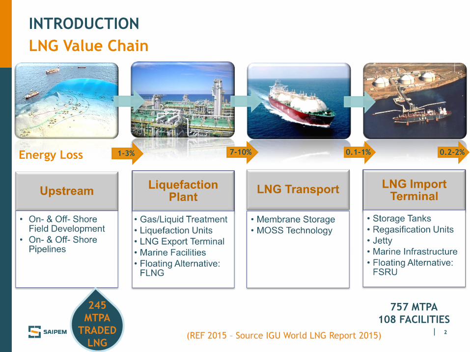
2 (REF 2015 – Source IGU World LNG Report 2015)
757 MTPA
108 FACILITIES
245
MTPA
TRADED
LNG
LNG Value Chain
INTRODUCTION
0.2-2% Energy Loss 1-3% 7-10% 0.1-1%

3
INTRODUCTION
LNG Regasification
LNG Regasification is an excellent chance to diversify energy sources
Global Regasification market continues to expand at a steady pace
LNG supply is increasing thanks to new
Liquefaction plants entering into the
production phase
IGU World LNG Report 2016
Global Regasification capacity: 757 MTPA
Increase from 2014: 33 MTPA, +5%
Floating Regasification: 77 MTPA, +35% yoy

4
ENERGY EFFICIENT LNG REGASIFICATION TECHNOLOGIES
Recover Energy – Reduce Emissions
FSRU TOSCANA Offshore (Italy)
Saipem, in cooperation with POLIMI (Politecnico di Milano)
studied possible schemes to improve energy efficiency in Regasification
assessed several HELE alternatives, with various flow diagrams now available
investigated the market for Equipment technical feasibility and Economics
Import Terminals pay considerable expenses for electrical power import
Low usage, recurring seasonally, increases power cost weight on income
Possible Carbon Tax would further increase the costs for power consumption

5
ENERGY REQUIREMENTS
Thermal and Electric Power
216,000 m3
(1,362 GWh)
2.25 MWe 27 MWt
TNG = 3°C
P=63÷84 barg
SCV
987 kg/h
NG 1000
kg/h
LNG
Regasification
line
ORV
Regasification
line
CO2: 45 kg/h CO2: 9.5 kg/h 16.2 kWe 23.3 kWe
1000
kg/h
LNG
1000
kg/h
NG
LNG: 139 t/h
TLNG= -160 °C
TSW = 9°C

6
ENERGY EFFICIENT LNG REGASIFICATION TECHNOLOGIES
Energy Recovery Performances
0
-100
Performance indexes Target

7
Technologies Overview
Direct expansion, pumping the cryogenic LNG to high pressures and
expanding the regasified LNG to delivery pressures
Cogeneration, producing simultaneously electric and thermal power
from burning a fraction of the regasified LNG
Gas Cycle, producing electric power from a fraction of the regasified
LNG rejecting heat (thermal power) to regasify LNG
Organic Rankine Cycle (ORC), producing electric power using
seawater as an energy source and rejecting heat to regasify LNG
ENERGY EFFICIENT LNG REGASIFICATION TECHNOLOGIES

8
ENERGY EFFICIENT LNG REGASIFICATION TECHNOLOGIES
Direct Expansion: Concepts & References
LNG is pumped at a higher pressure than
network and is vaporized by a heat source
(seawater or SCV at high temperature)
HP Natural Gas is then expanded to
transform mechanical energy into
electrical energy by using an expander
coupled to a power generator
Himej direct expansion layout
References (Japan) Year
Sodegaura 1979
Senboku Daini 1982
Kitakyushu 1982
Tobata 1982
Himej 1984
Chita 1984
Yokkaichi 1989
Chita LNG Import Terminal

9
Direct Expansion: application schemes
Direct Expansion linked to ORV
Nikkiso: Booster Pump
ENERGY EFFICIENT LNG REGASIFICATION TECHNOLOGIES
Direct Expansion linked to SCV
L.A. Turbines Turbo-expander

10
ENERGY EFFICIENT LNG REGASIFICATION TECHNOLOGIES
Cogeneration: Concepts & References
Zeebrugge plant scheme
COGENERATION: simultaneous generation of
electricity and recovery of heat from a single
source and via a single process
UNBALANCE:
Heat/power ratio of LNG line: 8÷10
Heat/power ratio of Cogenerator: 1÷3
Heat recovery from exhaust gas via water
closed loop provides only part of thermal duty
References – on stream plants:
Andres, Himeji, Kochi, Manzanillo, Penuelas,
Zeebrugge
Penuelas Import Terminal

11
ENERGY EFFICIENT LNG REGASIFICATION TECHNOLOGIES
Cogeneration: Main Components Feasibility
Solar: Gas Turbines
Bergen: Internal
combustion Engine
(Other Vendors: GE
Jenbacher, Wartsila)
GE: PGT16
(Alternative: PGT25)
Gas Turbines
Internal Combustion Engines

12
ENERGY EFFICIENT LNG REGASIFICATION TECHNOLOGIES
Gas Cycles: Concepts
FLUID Argon Nitrogen Helium Air
MW [kg/kmol] 39.95 28.01 4.00 28.96
Critical temperature [°C] -122 -146 -268 -140
Critical pressure [bar] 48.6 33.9 2.3 38.5
GAS CYCLE: Brayton Cycle where the working fluid operates between a low
temperature boiler and a cold sink

13
ENERGY EFFICIENT LNG REGASIFICATION TECHNOLOGIES
Gas Cycles: Main Components Feasibility
Cannon: Boiler Atlas Copco: Integrally geared
Generator turbo-expander
Heatric: Printed Circuit Heat Exchanger (PCHE)

14
ENERGY EFFICIENT LNG REGASIFICATION TECHNOLOGIES
Organic Rankine Cycles: Concepts & References
Negishi plant
Rankine thermodynamic cycles using a suitable
organic fluid instead of water (steam)
Exploits the cold heat sink to produce power
Working fluid selection:
thermodynamic, economical, hazard aspects
Large variety of Organic Fluids:
different plant configurations additional
criteria: safety, min. pressure/temperature
Himeji Osaka gas
LNG Tank
TLNG -160°C
Generator
Organic
Fluid Condenser
Vaporizer
NG
Sea Water
TSW= 9°C
Pump
Turbine
References:
Japan, installations in
LNG terminals (80’s)
ORC often coupled
to other technologies

15
ENERGY EFFICIENT LNG REGASIFICATION TECHNOLOGIES
Organic Rankine Cycles: Main Components Feasibility
Working fluid - LNG HEAT EXCHANGER:
S&T Vendors, Heatric (Printed Circuit)
Working fluid - SEA WATER:
S&T Vendors
CRYOGENIC PUMPS:
Ebara, Nikkiso, JC Carter, Ruhrpumpen, Cryostar
TURBINES :
• Radial inflow: L.A. Turbines, Cryostar, Atlas Copco
• Radial outflow: Exergy
• Axial: Ormat, Turboden
Ebara: vertical in-pot pump
L.A. Turbines:
Radial inflow turbine

16
ENERGY EFFICIENT LNG REGASIFICATION TECHNOLOGIES
Organic Rankine Cycles: Single Level
No assessed fluid covers the entire regasification line power demand
The constraint of Tcond has a small effect on power production
High critical temperature fluids penalized due to minimum condensing
pressure constraint

17
ENERGY EFFICIENT LNG REGASIFICATION TECHNOLOGIES
Organic Rankine Cycles: Single Level
SINGLE LEVEL
Pure fluid
Single condensation level
recuperative
TWO LEVELS
Pure fluid
Two condensation levels
Recuperative AP and BP
CASCADE
Two single level cycles
different pure fluids
recuperative TOP cycle
economizer BOTTOM cycle
ORC net power is not sufficient
Pla
nt
com
ple
xit
y

18
ENERGY EFFICIENT LNG REGASIFICATION TECHNOLOGIES
Comparison Results
Cogeneration
NG
1.146 MTPA
8200 tons/yr
ORC Organic
Rankine Cycle
NG
1.154 MTPA
0 tons/yr
Gas
Cycle
NG
1.143 MTPA
11000 tons/yr
Direct
expansion
16000 tons/yr
CO2: -26000 tons/yr CO2: -2300 tons/yr
CO2: -23000 tons/yr CO2: -12500 tons/yr
(-50000 tons/yr)
ORV (SCV) SCV
SCV SCV
LNG
1.154 MTPA
NG
1.138 MTPA LNG
1.154 MTPA
LNG
1.154 MTPA
LNG
1.154 MTPA
FCS = -100%
FCS = -58%
FCS = -43%
FCS = -5%

19
COST AND PROFITABILITY ANALYSIS
Technology Economic Comparison
0
50
100
150
200
250
300
350
Italy Poland Malaysia India China Tota
l Lif
e C
ost
(T
LC
), M
M$ Total Life Cost
Cogen ORC Gas Cycle SCV ORV
0
5
10
15
20
Italy Poland Malaysia India China
Payback T
ime (
PBT
), y
r
Payback Time, vs ORV
Carbon Tax:
35 $/ton
0
5
10
15
20
Italy Poland Malaysia India China Payback T
ime (
PBT
), y
r
Payback Time, vs SCV
Cogen ORC Gas Cycle
0
50
100
150
200
250
300
350
CA
PEX,
MM
$
CAPEX

20
CONCLUSIONS
LNG Regasification Terminals play a strategic role in the energy sources
diversification, with a particular emphasis in Europe
Saipem and POLIMI have analyzed various solutions to improve the energy
efficiency of Regasification Terminals
Several schemes are available to fit the needs of different plants, in terms of
size, location and constraints
These schemes, assessed with information from executed EPC projects and
referenced equipment manufacturers, are now available for a field application

21
Thank you
www.saipem.com