refractomax521 ri detector - thermo fisher scientific ri detector ... long-lifetime tungsten lamp is...
TRANSCRIPT

RefractoMax521 RI Detector Operator’s Manual High Sensitive Refractive Index Detector for High Performance Liquid Chromatography
Publication No. 77-5017-11
Auto Zero Purge Enter Error
Power
RefractoMax 520


Important Notice
The information contained in this manual is subject to change without notice.
ERC Inc. (ERC) assumes no responsibility for any errors that may appear in this manual.
This manual is believed to be complete and accurate at the time of publication.
In no event shall ERC be liable for incidental or consequential damages in connection
with or arising from the use of this manual.
Spare Parts Availability
It is the policy of ERC to provide maintenance spare parts for a period of seven (7)
years after the final production of the instrument. Spare parts may be available after
the seven (7) year period but only on an “as available” basis.
The following is a Federal Communication Commission advisory:
WARNING:
This equipment generates, uses, and can radiate radio frequency energy and if not
installed and used in accordance with the instruction manual may cause interference to
radio communications. It has been tested and found to comply with the limits for
Class A computing device pursuant to Subpart J of Part 15 of FCC rules, which are
designed to provide reasonable protection against such interference when operated in a
commercial environment. Operation of this equipment in a residential area is likely
to cause interference in which case the user at his own expense will be required to take
whatever measures may be required to correct the interference.

Operating Instructions
This manual is provided to help you establish operating conditions that will make safe
and efficient.
Special considerations and precautions are also described in this manual that shall
appear in the form of WARNING, CAUTION and NOTE as described below.
It is important that you operate and service equipment in accordance with this manual
and any additional information that may be provided by ERC from time to time.
note
note
Teflon® is Registered Trademark of E.I. du Pont de Nemours and Company.
Alerts you to potentially hazardous situations
that could result in serious injury, and how to
avoid these situation
Alerts you to situations that may cause
moderate injury and/or equipment damage,
and how to avoid these situations.
Information to help you to achieve optimal
performance from your equipment.
The following Trademarks and Registered
Trademarks are found in this manual.

Before Starting:
RefractoMax521 Refractive Index Detector is designed to be an analytical device for
pure research purpose and may not be suitable for in vitro diagnostic analysis.
To operate RefractoMax521 Refractive Index Detector properly, you are strongly
recommended to go through this Service and Maintenance Manual. Improper use of
this detector shall be dangerous and may cause a hazardous result.
Limited Warranty Policy
ERC warrants its products against defects in materials and workmanship for the period
of twelve (12) months from the date of shipment out of its factory.
ERC will, at its option, repair or replace products that are proved to be defective.
The aforementioned warranty policy shall not be applied to defects being caused by:
(1) Improper or Inadequate maintenance, adjustment, calibration or operation by the
user(s);
(2) User-supplied software, hardware, interfacing or consumable;
(3) Unauthorized modification or misuse;
(4) Operation outside of the environmental and electrical specifications for the
product.
(5) Improper site preparation and maintenance; or
(6) User induced contamination or leaks.


INDEX
Section 1. Introduction ······································································································· 1
1-1. Principle of refractive index detection ·············································································· 2
1-2. Specifications ···················································································································· 4
Section 2. Unpacking and Installation ········································································· 5
2-1. Installation Site Requirements ·························································································· 6
2-2. Power Requirements ········································································································· 6
2-3. Unpacking and Inspection ································································································· 6
2-4. Standard Accessories ········································································································ 7
2-5. Loosing the locking screws ································································································ 8
2-6. Making a connection ········································································································· 8
2-6-1. Power Line ················································································································· 8
2-6-2. Replacing Fuse ··········································································································· 9
2-6-3. Tubing Connections ································································································· 10
2-6-4. Cable Connections ··································································································· 10
2-7. Solvent Recommendations ·····························································································11
2-8. Characteristics of commonly used mobile phase ····························································13
Section 3. Function Keys and Displays ······································································· 14
3-1. Front Panel ······················································································································15
3-2. Rear Panel ·······················································································································16
3-3. Side View ·························································································································16
3-4. LCD Display (User Screens) ······························································································17
3-4-1. Default Screens (Start Up Screens)·········································································· 17
3-4-2. Screen Sequence ····································································································· 17
3-4-3. Parameter Setting Screen ························································································ 18
3-4-4. Auto Set Up Information Screen ············································································· 21
3-4-5. Validation Information Screen ················································································· 22
3-4-6. Validation Execute Screen ······················································································· 23
3-4-7. Error Messages ········································································································ 24
3-4-8. Other Messages······································································································· 25
Section 4. Getting Started ······························································································ 26
4-1. Just in Case ! ····················································································································27
4-2. Start Up ·························································································································· 27
4-3. Parameter Setting ·········································································································· 27
Section 5. Maintenance and Validation ···································································· 28
5-1. Cell Cleaning ··················································································································· 29
5-1-1. Preparations ············································································································ 29
5-1-2. Cleaning ··················································································································· 29
5-2. Validation ························································································································ 31
5-2-1. Validation Information ····························································································· 31
5-2-2. Span Validation ········································································································ 32
5-2-3. Auto Set Up Execute ································································································ 33
Section 6. Shutdown Procedure ··················································································· 35
6-1. Corrosive Solvents ·········································································································· 36
6-2. No Flow Shutdown Versus Reduced Flow Shutdown ····················································· 36
6-3. Long-Term Storage ·········································································································· 36
Section 7. Troubleshooting ····························································································· 37
7-1. Introduction ···················································································································· 38
7-2. Make sure how the detector itself is working. ······························································· 38
7-3. To isolate the cause of problem ····················································································· 38
7-4. Troubleshooting (Diagnosis Chart) ················································································· 39

1
Section 1. Introduction

2
1-1. Principle of refractive index detection
RefractoMax521 Refractive Index Detector (called as “RefractoMax521” hereafter) is a
high-performance universal detector designed for analyses requiring the continuous monitoring of
the refractive index of a flowing liquid with respect to a reference.
RefractoMax521 is a deflection or Snell type refractive index detector. Snell's law states that a
parallel light beam, when passing through a dielectric interface separating two media of different
refractive index at an angle of incidence greater than zero, will be refracted as a function of the
magnitude of difference of the refractive indices of the two media.
Snell's Law
Optical System of RefractoMax521
[1] Tungsten lamp [2] condense lens [3] First Slit [4] Collimator Lens
[5] Second Slit [6] Flow Cell [7] Mirror [8] Null Glass [9] Photodiode
Light from a low-power, long-lifetime tungsten lamp is collimated by a lens and slit and passed
through reference and sample cells, reflected off a mirror, passed back through the optical cells, and
focused by lenses onto a pair of photo sensing diodes (photo sensor).
incident beami
rrefracted beam
interface
n = index of refraction
i = angle of incidence
r = angle of refraction
v = velocity of light in first medium
v1 = velocity of light in second medium

3
During operation, RefractoMax521’s reference and sample cells are filled with mobile phase. The
reference cell is then isolated from the flow path and mobile phase flows through the sample cell
only. As long as no difference exists between the refractive indices of the media of the two cells,
there is no refraction of the light passing through them.
[1] Light Beam [2] Sample Cell [3] Reference Cell [4] Light Axis (Ns>Nr)
[5] Light Axis (Ns=Nr) [6] Distance between …[4]&[5] at the photo sensor
[7] Photo sensor
Ns: Refractive Index of mobile phase in Sample Cell
Nr: Refractive Index of mobile phase in Reference Cell
The light shines on a pair of photodiodes, each of which gives an electrical signal; these signals are
amplified and the difference between the two signals is measured. Zero refraction should generate a
zero-volt difference in these signals. An electrically controlled mechanical linkage allows the user to
optimize the photodiodes’ outputs for zero deflection via a refractive lens in the optical path.
Additional circuitry enables the user to easily correct the signal output to electronic zero.
Ns = Nr Ns > Nr
[1] photo sensor A [2] photo sensor B [3] light beam
When a change occurs in the refractive index of the mobile phase, the light passing through the
interface between the sample and reference cells is refracted, causing the light intensity on one
photodiode to increase and on the other to decrease. This difference gives a signal having both
amplitude and polarity; the signal is amplified to drive a chart recorder or integrator.

4
1-2. Specifications
Construction Deflection type Refractive Index Range 1.00 ~ 1.75
Range 1/4 ~ 512 RIU
Linearity 600 RIU
Noise ≤2.5 nRIU( Response : 3 seconds )
Response Time 0.1, 0.25, 0.5, 1.0, 1.5, 2, 3, 6 sec. Polarity Positive/Negative Auto Zero Optical & Electrical Auto-Zero Auto Zero Range All Refractive Index Range
Auto Zero Resolution ≤1 (@8mV/RIU) / 4 (@2mV/RIU) nRIU
Offset Range 0 to 500mV (same with Integrator output sensitivity) Offset Resolution 10mV (same with Integrator output sensitivity)
Integrator Output 0 to 1V/FS (Sensitivity: 2mV/RIU, 8mV/RIU) Recorder Output 0 to 10mV/FS
Event Marker Marker out: ≥5% of FS
Temperature Control OFF, 30 to 55oC (1
oC increment): 80
oC Thermal Protector
Operator Support Span Check/Validation Display External Communication RS232C
Cell Volume 8l Maximum Flow Rate 10 ml/min (mobile phase: pure water) Pressure Rating 50 kPa (0.5 kgf/cm
2)
Internal Volume Inlet Port / Flow Cell: approx. 60l
Flow Cell / Outlet Port: approx. 480l
Total: approx. 540l Wetted Material SST316, Teflon, Quarts Glass Power Requirement AC100 ~ 240V +/- 10%: 50-60Hz Power Consumption 120VA maximum Dimensions H150 x W260 x D450 (mm) Weight 12 kgs (26 lbs) EMC Standards EN61326-1,EN61326-2-1 Safety Standards EN61010-1
Conditions to secure safety (EN61010-1)
Indoor use Altitude up to 2000m Temperature 5
oC to 40
oC
Maximum relative humidity 80% for temperatures up to 31oC
decreasing linearly to 50% relative humidity at 40oC
Transient over voltages according to installation category Ⅱ
Pollution Degree 2 in accordance with IEC 60664

5
Section 2. Unpacking and Installation

6
2-1. Installation Site Requirements
To install RefractoMax521, please make sure that any of followings shall be kept away from it to
prevent interference on your analysis. Refractive Index Detector, in general, is very sensitive to
the change in ambient temperature and airflow that results a drift of baseline.
Air fan (air-conditioner-cooler, heating equipment and ventilation)
Open doors or windows
Direct sunlight
Dart or dusts
Vibration source
Electro-Magnetic Wave or High Frequency
2-2. Power Requirements
RefractoMax521 requires 50-60 Hz single-phase power source capable of providing AC 100/240V
+/- 10%.
Running RefractoMax521 on a voltage other than the correct single-phase supply will void the warranty.
RefractoMax521 is designed to operate with single-phase (phase-neutral) power ONLY. If your facility provides only phase-phase (i.e., three-phase) power consult ERC.
2-3. Unpacking and Inspection
This section describes in details how to install RefractoMax521. This detector is designed to be
operator installed.
Each steps of the installation site preparation must meet local safety, electrical, and building codes. These codes take precedence over any recommendations in these instructions, and compliance to them is the responsibility of the customer.
RefractoMax521 weighs 12 kgs (26 lbs). Use proper lifting techniques to avoid potential injuries. To remove the detector from the box, hold the bottom of the cabinet. Never attempt to lift by front panel or terminals.
RefractoMax521 is packed with a number of accessories. Do not discard the packing material until all parts are accounted for.
Check the detector carefully for evidence of shipping damage.
If there is any evidence of damage, any item(s) missing in the carton or discrepancies, please notify that to the carrier immediately and to ERC.
CAUTION
CAUTION
CAUTION
CAUTION
CAUTION
CAUTION

7
2-4. Standard Accessories
Image Description Part Number Thermo
Scientific™
Sales P/N
Quantity
RS-232 Ext. Cord,
Modem Cable,
5 m
8914.0143 8914.0143 1
RS-232<>USB
Interface Cable
8073.2000 6073.2000 1
Outlet Tubing,
PTFE, 2.5 × 1.5 ×
1500 mm, with
nut and ferrule
8809170 6060.1239 1
Fuse, 3.15 A 2401120 Included in
6810.9011
2
Operator´s
Manual
n.a. n.a. 1
Note: The detector is equipped with a power cord that is appropriate to your power source.

8
2-5. Loosing the locking screws
To prevent damage may occur during the shipment, the optical block is fixed by two (2) locking
screws (5mm Allen bolts). As you are installing RefractoMax521, please make sure to loosen
these screws.
1. Move RefractoMax521 to the side of a bench to make the locking screws accessible while
supporting it to prevent it from falling.
2. Loosen the locking screws, but do not remove them, using the 5mm hexagonal key.
3. Move the detector securely back onto the bench.
Once the locking screws were loosened, the rubber insulator equipped with the optical block
becomes functional and absorb an external shock or vibration.
Do not remove the screws. Do not run them out so far that the detector’s weight rests on the screw heads instead of its feet.
Detector will not stabilize if locking screws are not loosened
2-6. Making a connection
2-6-1. Power Line
The power switch is located on the lower left of front panel as viewed in 3-1. The power should be
OFF before connecting the power cord to the detector. The receptacle for the power cord is located
on the rear of the detector. Refer to 3-2.
Connect the end of grounding cable to the ground terminals on the back panel and to a known
ground.
Electrically conducting spills can occur when conductive HPLC solvents are spilled on or in the instrument. Ground the instrument properly to protect the operator from electrical shock. Proper grounding also protects the instrument from power line noise. Verify that the instrument is properly grounded through the power line ground terminal. Do not remove or otherwise disable the power cord's ground prong.
CAUTION
note
WARNING:
SHOCK HAZARD

9
2-6-2. Replacing Fuse
Replace only with same type and rating of fuse. Fuse for RefractMax521: 3.15A(T3.15AL/250V)
To remove fuse holder
To re-install fuse holder
WARNING:
FIRE HAZARD
Turn off the power of detector.
Remove the power cord.
Push the lever located just above of
Fuse holder cover. Pull the holder
out as you hear clicking sound.
Replacing fuse.
Push the fuse holder in until clicking
Sound is heard.
Make sure the holder is locked.

10
2-6-3. Tubing Connections
Connection to the Inlet
RefractoMax521 must be the last component in your LC system. No detector or backpressure regulator can follow it. Do not use narrow-bore tubing for the outlet.
Hook up the narrow-bore stainless steel tubing of the Standard (0.25 mm ID, 1M long)
with the inlet (IN) port of front panel.
Connection on the Outlet Side
Hook up Teflon® tubing (1.5 mm ID, 1.5 m long) of the Standard with the outlet (OUT)
port of front panel. Lead the opposite end of tubing into drain bottle.
Do not expose the purge valve against backpressures greater than 50 kPa (7 psi). Also, never subject the reference and sample cells to back pressures greater than 700 kPa (100 psi). High backpressures can break the cells.
2-6-4. Cable Connections
The GROUND terminals, on the lower right side of the rear panel (see), are not the same as the recorder ground or Integrator ground terminals. Do not inter change these connections.
Integrator Connection
Using the output signal cable supplied in the Standard, connect one end to integrator, white
lead to integrator negative (–) and red lead to integrator positive (+).
Connect the third lead to the GROUND (FG).
Recorder connection
Using the output signal cable supplied in the Standard, connect one end to the chart
recorder, white lead to recorder negative (–) terminal and red lead to recorder positive (+).
Connect the opposite end to the recorder’s 10 mV terminal.
Connect the third lead to the GROUND (FG).
Red lead
White lead
Red lead
White lead
CAUTION
CAUTION
CAUTION

11
2-7. Solvent Recommendations
Grade of Solvents
HPLC grade solvents are recommended for better instrument performance and
chromatographic data.
Solvent Filtering
All solvents, including deionized water, should be filtered by in-line solvent filter.
Solvent Degassing
Solvents should be properly degassed prior to use. Solvents that are not properly degassed may
cause bubble formation in pump heads and in the detector cells potentially causing pressure
flow problems and a noisy chromatographic baseline. Degassing is especially critical when
the column temperature is elevated above room temperature, or with solvents that have a high
gas solubility, e.g., methanol. Analysis times that run greater than 5 to 6 hours will also require
degassing of solvents.
On-line (continuous) solvent degassing is most ideal to have a constant state of mobile phase
solvent over time, as the degassed solvent would start reintroducing the air.
Additional Precautions
Some solvents may corrode the wetted surfaces of the detector, if they are left in the detector
after operation. The quartz cell window is easily etched by strong bases. It is recommended that
some solvents be rinsed from the detector for overnight and weekend storage.
The solvents used with the detector are limited by the materials used for the wetted parts they
come in contact with (e.g., quartz glass, Teflon® and 316 stainless steel). These limitations
should be considered as you are choosing mobile phase solvents.
When an organic solvent that contains halogens, such as chloroform and methylene chloride, is
used, flush out entire flow path with a solvent compatible with your chromatographic condition.
(for example, hexane or another hydrocarbon)
For isocratic work with a normal phase column, the alcohols methanol or 2-propanol, a
non-carcinogenic aromatic such as the xylenes, acetone, or an ether that is non-volatile and not
a ready producer of peroxides can be used. DO NOT use ethyl ether.
If a solvent listed below is in use, flush out all the flow path sufficiently with an inert solvent
that is compatible with your chromatographic system. Buffers, acids, and other highly ionic
aqueous solutions should be flushed out with large amounts of water (5-10 times the volume of
liquid from pump head to detector outlet If you neglect this flushing, the pump, injector, and
column may become corroded and badly damaged.
Sulfuric Acid, Boric Acid, Citric Acid, Acetic Acid, Lactic Acid,
Acetic Anhydride, KOH, NaOH, Hydrazine, Sodium formate
Ammonium salts: -formate, -perchlorate, - nitrate, -citrate, -oxalate, -sulfate, -H2PO4, 2CO3
K, Na salts: -bicarbonate, -chlorate, -nitrite
Following solvents should be avoided.
Hydrohalogenic, Metal Halides >2M, KCl, Ammonium Halides,
Ammonium Formate, All hypochlorites, Tetrachloromethane
Acids: HCl, HF, etc.

12
Fluorocarbon solvents will alter Teflon® over long exposure. Flush with pentane or another light hydrocarbon.
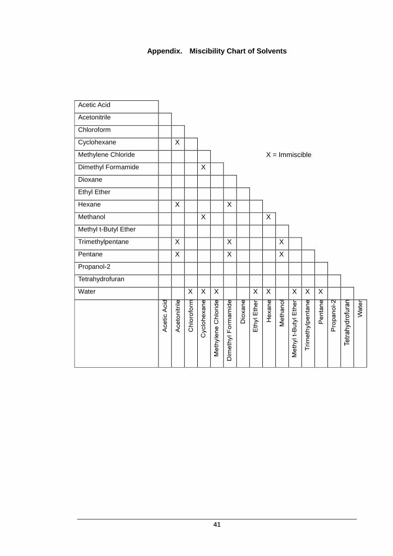
If you want to replace one solvent with an immiscible one, flush out the existing mobile phase with an intermediary solvent inter-miscible with your initial and final solvents. For example, you want to replace water in your HPLC with chloroform; water and chloroform are immiscible. Replace the water in your system with 2-propanol, which is freely miscible with water and chloroform. When you are certain all water is removed, replace the 2-propanol with chloroform. See the Miscibility Chart in Appendix.
CAUTION
note

13
2-8. Characteristics of commonly used mobile phase
(Those in bold should not be employed)
Polarity
E2(Al2O3)
Viscosity
CP20 oC
Refractive
Index
UV
Cut-off
(nm)
Flash
Point
(oC)
Fire Point Vapor
Density
Boiling
Point
(oC)
Gravity (oC) Upper Lower
Fluoroalkanes -0.25 1.25
n-Pentane 0.00 0.23 1.358 210 <-40 308.9 1.5 7.8 2.5 36.1 0.6
Hexane 0.00 1.375 210 -21.7 233.9 1.2 7.5 3.0 68.9 0.7
Isooctane 0.01 1.404 210
Petroleum ether 0.01 0.3 210
n-Decan 0.04 0.92 1.412 46.1 207.8 0.8 5.4 4.9 173.9 0.7
Cyclohexane 0.04 1.00 1.427 210 -20 260 1.3 8 2.9 81.7 0.8
Cyclopentane 0.05 0.47 1.406 210
Diisobutylene 0.06 1.411 210
i-Pentene 0.08 1.371 -17.8 272.8 1.5 8.7 2.4 30 0.7
Carbon disulfide 0.15 0.37 1.626 380 -30 100 1.3 44 2.6 46.1 1.3
Carbon tetrachloride 0.18 0.97 1.466 265
Amyl chloride 0.26 0.43 1.413 225 12.8 343.3 1.6 8.6 3.7 106.1 0.9
Busy chloride 0.26 1.436 220 -9.4 460 1.8 10.1 3.2
o-17.2 463.9 1.6 6.0 144.4
Xylene 0.26 0.62-0.8 to 1.50
290 m-25 527.8 1.1 7.0 3.78 138.9 0.9
p-25 528.9 1.1 7.0 138.3
i-Propyl ether 0.28 0.37 1.368 220 -27.8 443.3 1.4 21 3.5 68.9 0.7
i-Propyl chloride 0.29 0.33 1.378 225 -32.2 593.3 2.8 1037 2.7 35 0.9
Tolune 0.29 0.59 1.496 285 4.4 536.1 1.4 6.7 3.1 110.6 0.9
n-Propyl-chloride 0.30 0.35 1.389 225 <-17.8 2.6 11.1 2.7 46.1 0.9
Chlorobenzene 0.30 0.80 1.525 32.2 637.8 1.3 7.1 3.9 132.2 1.1
Benzene 0.32 0.65 1.501 280 -11.1 562.2 1.4 7.1 2.8 80 0.9
Ethyl bromide 0.37 1.424 511.1 6.7 11.3 3.8 37.8 1.4
Ethyl ether 0.38 0.23 1.353 220 -45 180 1.9 48 2.6 35 0.7
Ethyl sulfide 0.38 0.45 1.442 290
Chloroform 0.40 0.57 1.443 245
Methylene-chlolride 0.42 0.44 1.424 245 -50 518.9 3.8 15.4 2.2 38.5 0.9
Methyl I-butyl ketone 0.43 1.394 330
Tetrahydrofurane 0.45 1.408 220 -14.4 321.1 2 11.8 2.5 66.1 0.9
Ethylen dichloride 0.49 0.79 1.445 230 13.3 412.3 6.2 16 3.4 83.9 1.3
Methyl ethyl ketone 0.51 1.381 330 -6.1 515.6 1.8 10 2.5 80 0.8
i-Nitropropane 0.53 1.400 380 48.9 420.6 2.6 3.14 131.1 1.0
Acetone 0.56 0.32 1.359 220 -17.8 537.8 2.6 12.8 2.0 56.7 0.8
Dioxane 0.56 1.54 1.422 260 12.2 180 2.0 22 3.0 101.1 1.0
Ethyl acetate 0.58 0.45 1.370 260 4.4 460 1.8 8 3.5 90 0.9
Methyl acetate 0.60 0.37 1.362 210 -10 501.7 3.1 16 2.6 60 0.9
Amyl alcohol 0.61 4.1 1.410 32.8 300 1.2 10.0 3.0 137.8 0.8
Dimethyl sulfoxide 0.62 2.24
Aniline 0.62 4.4 1.586 70 617.2 1.3 3.2 184.4 1.0
Dimethyl amine 0.63 0.38 1.387 275 <-17.8 312.2 1.8 10.1 2.5 56.7 0.7
Nitromethane 0.64 0.67 1.394 380 35 418.3 7.3 2.1 101.1 1.1
Acetonitrile 0.65 0.37 1.344 210 5.6 1.4 81.7 0.8
Pyridine 0.71 0.94 1.510 305 20 1.8 12.4 2.7 115 1.0
Butyl cellosolve 0.74 220
i-Propanol n-Propanol
0.82 2.3 1.38 210 11.7 398.9 2.0 12 2.1 82.8 0.8
Ethanol 0.88 1.20 1.361 210 12.8 422.8 4.3 19 1.6 78.3 0.8
Methanol 0.95 0.60 1.329 210 11.1 463.9 7.3 36 1.1 63.9 0.8
Ethylene glycol 1.11 19.9 1.427 210 111.1 412.8 3.2 197.2 1.1
Acetic acid large 1.26 1.372

14
Section 3. Function Keys and Displays

15
3-1. Front Panel
[1] Power Switch: Press this key once to turn on or off the unit.
[2] Event Marker Key: Press to generate a marker signal. (5% of Full Scale)
[3] Purge Key: Press to turn purge valve on or off to change flow path.
When the valve is on, LED above the key illuminates
and “PURGE” appears on the lower line of LCD
display. Solvent flows through reference side of flow
cell instead of sample side.
[4] Auto Set Up Key: Press this key to do Auto Set Up. As “Auto Set Up” is
going on, LED above the key illuminates and “AUTO”
appears at the lower line of LCD display.
[5] Auto-Zero Key: Press this key to do Auto-Zero. As Auto-Zero is going
on, LED above is illuminated and “AUTO ZERO”
appears on the lower line of LCD display.
[6] LCD Display: Liquid Crystal Display
[7] Arrow Keys: Press to change screen, to move cursor or to edit
values.
[8] Outlet Port:
[9] Inlet Port:
[10] Enter Key: Press to save the edited data or to confirm the
command.
[11] Cancel Key: Press this key to scrap the edited data.
[12] Escape Key: Press this key once to return to Monitor Screen.
[13] Error LED: Error message
[5] [2] [3]
[9]
[8]
[12] [10] [11]
[1]
[13]
[6]
[4]
Auto Zero Enter Error
Power
RefractoMax 520
IN
OUT
[7]

16
3-2. Rear Panel
[11] MAKER IN: External Signal In (Event Marker)
[12] ZERO IN: External Signal In (Auto Zero)
[13] PURGE IN: External Signal In (Purge On)
[14] ERROR OUT: Signal Out (Error)
[15] LEAK OUT: Signal Out (Solvent Leak)
[16] READY OUT: Signal Out (Ready)
[17] INTEG. OUT: Integrator Out
[18] FG: Ground for signal cable
[19] REC. OUT: Recorder Out
[20] COM: RS-232C Port
[21] Ground Terminal
[22] Power Inlet
3-3. Side View
[11]
[12]
[13]
[14] [15] [16] [17] [18]
[19]
[20]
[21]
[22]

17
3-4. LCD Display (User Screens)
RefractoMax521 has a LCD display on the front panel as shown in 3-1. Front View here above. The
display consists of following four screens.
3-4-1. Default Screens (Start Up Screens)
Model name and Program version number show up as the power switch is on.
“INITIALIZING” appears during the initialization.
Monitor screen shows up after the initialization. “TEMP.UNSTABILIZED” indicates the unit has not reached to the default temperature (35
oC) yet.
As the unit reaches the default temperature (35
oC)
“TEMP.UNSTABILIZED” goes off and “RD” shows up on the upper line (Ready).
When RefractoMax521 finished the initialization, LCD Display will automatically shows “Monitor Screen”. Should the screen have a message “TEMP. UNSTABILIZED” originally, you may go ahead reviewing and/or editing those parameters by using Arrow Keys and other functional keys.
3-4-2. Screen Sequence
By pressing Arrow Keys, LCD Display will change from one screen to the other as follow
note
Refractoamax 521
Ver.RA21E01
INITIALIZING
0.0 RIU 35oC
TEMP.UNSTABILIZED
0.0 RIU 35oC RD
1.00 RIU 35oC PARAMETER
SETTING
AUTO SET UP
INFORMATION
VALIDATION
INFORMATION
VALIDATION
EXECUTE

18
3-4-3. Parameter Setting Screen
Parameter Setting Screen Home
Recorder Range Setting By pressing Enter key, a cursor appears to indicate the range is selectable. Select 512, 256, 128, 64, 32, 16, 8, 4, 2, 1, 0.5 or 0.25 by
pressing Up or Down Arrow keys.
Press Enter key to confirm the selection.
Integrator Range Setting By pressing Enter key, a cursor appears to indicate the range is selectable.
Select 500 or 125 by Arrow keys.
Press Enter key to confirm the selection.
Temperature Setting By pressing Enter key, a cursor appears to indicate the temperature setting is editable.
Select temperature between 30 and 55˚C or OFF by Arrow
keys.
Press Enter key to confirm the selection.
Time Constant Setting By pressing Enter key, a cursor appears to indicate the time constant is selectable.
Select 6, 3, 2, 1.5, 1, 0.5, 0.25 or 0.1 by Arrow keys.
Press Enter key to confirm the selection.
Polarity Selection By pressing Enter key, a cursor appears to indicate the polarity
is selectable. Select + or - by Arrow keys.
Press Enter key to confirm the selection.
Baseline Shift Setting By pressing Enter key, a cursor appears to indicate the baseline shift setting is editable.
Select baseline shift between 0 and 50 by Arrow keys.
Press Enter key to confirm the selection.
PARAMETER
SETTING
REC. RANGE 512uRIU PARAMETER
INTEG. RANGE 500uRIU PARAMETER
TEMPERATURE 35oC
PARAMETER
PARAMETER
TIME CONSTANT 3 SEC
PARAMETER
POLARITY +
PARAMETER
BASELINE SHIFT 0

19
Default Setting If you want to reset parameter setting and bring it back to default setting, press Enter key. A cursor and “NO” show up.
Select “YES” by Arrow keys. Press Enter key to confirm the selection.
Default Setting (2) After pressing Enter key above, this message shows up to reconfirm if you do want to bring it back to default setting.
Select “YES” by Arrow keys. Press Enter key. Parameter is changed back to default setting and the unit will beep. The LCD display goes back to Monitor Screen.
LCD Contrast Setting By pressing Enter key, a cursor appears to indicate that you can change LCD contrast.
Select contrast between 1 and 7 by Arrow keys. Press Enter key to confirm the selection.
Auto Set Up mode Setting By pressing Enter key, A setup changes a judgment standard by three kinds, FINE, STANDRD, and COARSE.
Select by Arrow keys. Press Enter key to confirm the selection
Auto Set Up mode
Fine Standard
Coarse (Default)
Purge Cycle 30 sec.
Number of Cycle 3
Time to Auto Zero 240 sec.
Equilibration Time 80 min. 60 min. 40 min.
Measuring Time 80 min. 60 min. 40 min.
Drift 100 nRIU/h 500 nRIU/h 2500 nRIU/h
Noise 50 nRIU
PARAMETER
LCD CONTRAST 4
PARAMETER
AUTO MODE STANDARD
PARAMETER
SELECT DEFAULT
ERASE
CURRENT SETTING? NO

20
Parameter Default Setting
Parameter Setting value Unit Default
REC. RANGE 0.25, 0.5, 1, 2, 4, 8, 16, 32, 64,
128, 256, 512 (12 steps) uRIU/10mV 512
INTEG. RANGE 125 or 500 uRIU/1V 500
TEMPERATURE OFF, 30 to 55 (increment: 1oC) Celsius 35
oC
TIME CONSTANT 0.1, 0.25, 0.5, 1, 1.5, 2, 3, 6 (8 steps) Second 3
POLARITY + or - N/A +
BASELINE SHIFT 0 to 50 (increment: 10mV) 10mV 0
SELECT DEFAULT YES or NO N/A NO
LCD CONTRAST 1 to 7 (increment: 1) N/A 4

21
3-4-4. Auto Set Up Information Screen
Auto Set Up Information Screen Home It moves to each setting screen by Up or Down Arrow keys.
Date of the latest Auto Set Up of this unit
Drift result of the latest Auto Set Up of this unit
Noise result of the latest Auto Set Up of this unit
AUTO SET UP
INFORMATION
LAST S.SEQ
DATE **.**.**
DRIFT 100.0 nRIU
NOISE 10.0 nRIU

22
3-4-5. Validation Information Screen
Validation Information Screen Home
Date of the latest Validation of this unit
Result (Span) of the latest Validation of this unit
Current Lamp Voltage of this unit
VALIDATION
INFORMATION
LAST VALIDATION DATE **.**.**
SPAN
512.5RIU
LAMP VOLTAGE
3.75V

23
3-4-6. Validation Execute Screen
Validation Execute Screen Home
Press Enter key to get into following screen sequence.
Validation Date Entry Screen
Refer to 5-2-2. Span Validation about the detail.
Zero Measurement Screen
Refer to 5-2-2. Span Validation about the detail.
Sample Measurement Screen
Refer to 5-2-2. Span Validation about the detail.
Span Validation Result Screen
Refer to 5-2-2. Span Validation about the detail.
Enter
VALIDATION
EXECUTE
INPUT DATE **.**.**
Enter
ZERO MAESUREMENT
PUSH ENTER 0.0
Enter
SAMPLE MEASUREMENT
PUSH ENTER 512.5
Enter
SPAN 512.5RIU
LAMP VOLTAGE 3.75V

24
3-4-7. Error Messages
To alert you about the situation that is hazardous or may cause a deterioration of your analysis,
RefractoMax521 flashes following five different error messages.
When this error message comes on, power off the detector at
once.
Please double-check if there is any solvent leak. In case
you cannot fix problems, please contact our local
representatives in your area.
Null Glass Home Position Error
This indicates the null glass doesn't come back to its home
position.
If you are commanding Auto-Zero via external control devise,
refer to the procedure for “Optical Balance Error.
If you have this error as you are turning on RefractoMax521,
please contact our local representatives in your area.
Overheating Error This indicates overheating of optical block. Please contact our local representatives in your area.
Optical Balance Error This indicates that Auto-Zero wasn’t successful. Insufficient solvent exchange of reference flow path might cause this.
Try purging procedure to fill reference flow path with fresh solvent at once.
Parameter Error
This indicates the units failed to store data.
HOME POSITION ERROR
600.0 RIU 35oC
100.0 RIU 70oC
OVERHEAT ERROR
100.0 RIU 70oC
OPT.BALANCE ERROR
100.0 RIU 35oC
PARAMETER ERROR
100.0 RIU 35oC
LEAKAGE ERROR
Solvent Leak Error
This indicates there is a solvent leakage inside of cabinet.

25
3-4-8. Other Messages
There are four other messages as described below. Some of them are more like a warning message.
Low Light Intensity
This indicates inadequate light intensity. There are several possible causes for this error as follow.
1. Different state of solvents between sample-side flow cell and reference-side flow cell. Purge reference-side flow path with fresh solvent.
2. Air bubble in flow cells. Repeat purge on and off with flow to remove the air bubble.
3. Optical axis is off from the center. Press Zero Key to do
“Auto-Zero”. 4. The flow cell is empty.
Unstable Temperature
This indicates temperature of optical system hasn’t met the preset temperature.
Purge
This indicates the purge valve is on. Solvent flows through both of reference cell and sample cell.
Auto-Zero
This indicates the Auto-Zero adjustment function is working.
0.0 RIU 35oC
INTENSITY
0.0 RIU 35oC
TEMP.UNSTABILIZED
0.0 RIU 35oC
PURGE
0.0 RIU 35oC
AUTO ZERO

26
Section 4. Getting Started

27
4-1. Just in Case !
Prior to operation, check the following one more time.
.
Locking screws are loosened.
Mobile phase solvent is freshly made and degassed well.
All wetted parts are chemically compatible to the mobile phase solvent.
Mobile phase flushed through the entire flow path; all incompatible or immiscible solvents
have been flushed out.
Cable connections are properly made to chart recorder, integrator, data system, or other
external equipment.
All tubing connections are properly made and checked for leaks.
Power cord is plugged into appropriate power receptacle.
Proper fuse is installed.
Drain tube is installed.
Power switch is ON.
Before activating the purge valve (LED light OFF), pump about 10 ml of liquid through the cell. This will flush possible dust or particulate matter and reduce the possibility of damaging the valve seals.
4-2. Start Up
(1) Start pumping mobile phase solvent at flow rate 1 ml/min to reference cell (Purge
On).
(2) Press Purge key in every 10 seconds to on/off the purge valve for few minutes.
(3) Keep pumping mobile phase solvent to reference cell for about 20 minutes from the
above step (2).
(4) Press Purge key to turn off the valve. Mobile phase solvent flows to sample -side flow
cell.
(5) Wait until the baseline is stabilized.
(6) Press Zero Key to do Auto Zero.
Wearing protective gloves and goggles is advised.
4-3. Parameter Setting
Set the parameter on Parameter-Setting Screen (Refer to 3-4-3).
CAUTION
WARNING: CHEMICAL HAZARD

28
Section 5. Maintenance and Validation

29
5-1. Cell Cleaning
In many cases, performance degradation in sensitive instruments equipped with flow-through cells
is caused by cell contamination. The use of filtered solvents with in-line solvent filters will protect
the cell from contamination and reduce the amount of cleaning required. However contamination
from trapped particulates or bubbles, from precipitates, or from thin films of residues can still occur.
5-1-1. Preparations
To introduce cleaning solution into RefractoMax521 by solvent delivery pump, connect a tubing
line directly from the pump to RefractoMax521 inlet port bypassing the column. Some cleaning
solutions should be injected, however, directly into the flow cells by syringe due to their high
corrosiveness or safety concern.
Remember that flow cells can stand with only up to 70 kPa (100 psi). So, gently flush the cells under all conditions. If you encounter a high backpressure in RefractoMax521, use extreme caution to proceed. You will be risking flow cell rupture, and flow cell assembly replacement is not a recommended customer procedure.
Clean all internal lines of RefractoMax521 by injecting cleaning solution with PURGE OFF, and inject cleaning solution again with PURGE ON.
Particulate matter can be removed by forcing liquid through the cell using the syringe. Sometimes it helps to reverse flow and inject in the outlet port.
5-1-2. Cleaning
Depends on the solvents in use, the cleaning procedure is varied. Following is a procedure for
typical.
(1) Inject cleaning solution (acetone) by syringe from the inlet port (5 ml).
(2) Inject de-ionized water by syringe from the inlet port (5 ml).
(3) Inject nitric acid solution (15%) by syringe from the inlet port (5 ml).
(4) Expel nitric acid solution completely by flowing de-ionized water adequately.
(5) Exchange de-ionized water with the mobile phase solvent.
If buffers or solutions of high salt content have been in use, the cells may be contaminated by
precipitated salt. Pumping a large amount of distilled, de-ionized water, such as 1 ml/min, for up to
several hours, is the simplest clean-up procedure.
An elevated cell temperature will speed dissolution. The water wash can be acidified, if the
precipitated salt is more soluble in acidic solutions. However, do not use strongly basic (pH 10 or
higher) solutions, as these will etch the refractive index cells.
If contamination is suspected when a non-aqueous solvent is in use, flush the cells with a solvent
that is (1) miscible with your mobile phase, (2) a good solvent for the predicted contaminant, and
(3) generally of greater polarity than your mobile phase.
CAUTION
note

30
Do not allow nitric acid to contact methanol. An explosion could result. Completely rinse the flow cell with water following cleaning with nitric acid.
Corrosive acids are used. Use extreme caution to avoid spillage on skin, clothing, or the instrument. Protective gloves are advised.
Never put hydrochloric acid in the cell. This acid in any concentration will corrode the cell. Diluted (10-20%) or concentrated nitric acid is a good cleaning solution. The sample and reference cells should be filled with water or air (blown dry) before proceeding.
Filled the syringe with cleaning solution and connect to the inlet port of the RefractoMax521.
Carefully inject the cleaning solution. For safety, make sure that outlet tubing is led to drain bottle.
Flush acid cleaning solutions from the cells with large amounts of water, such as 1 ml/min. Flush for
15 to 30 minutes.
For shutdown and storage, please review Section 6. Shutdown Procedure.
WARNING: CHEMICAL HAZARD
WARNING: EXPLOSION HAZARD
CAUTION
note

31
5-2. Validation
From time to time, you are recommended to validate your HPLC system to keep an accuracy and
credibility of your analysis.
5-2-1. Validation Information
Validation Information Screen Home
Date of the last Validation of this unit
Result (Span) of the last Validation of this unit
Lamp Voltage reading at the last Validation of this unit
This indicates an applied voltage to the lamp. As it exceeds 4.5V, purge the reference side flow path with fresh solvent at once. (Applied voltage to the lamp is automatically raised as light intensity from the flow cell drops. In many cases the reduction of intensity is due to dirt in the reference flow cell.) If the voltage stays high, you may want to replace the light source.
VALIDATION
INFORMATION
LAST VALIDATION
DATE **.**.**
SPAN
512.5 RIU
LAMP VOLTAGE
3.75V

32
5-2-2. Span Validation
To do Span Validation, follow the below procedure.
(1) Preparation of standard sucrose solution:
Weigh out 350 mg sucrose and transfer quantitatively to a volumetric flask.
Dissolve in the 100 ml de-ionized, filtered, degassed water and dilute to flask’s mark.
note Use freshly made sucrose solution always.
(2) Equilibrate RefractoMax521 by pumping de-ionized water through both reference and sample
cells. Use the same de-ionized water as that used to prepare the sucrose standard solution.
Start pumping at flow rate to 1 ml/min.
(3) Make sure that the baseline is stabilized and the drift is equal or less than 500 nRIU/h by
monitoring recorder chart.
Press Enter key to get into following screen sequence.
Validation Date Entry After pressing Enter key above, this screen shows up for you to enter the date (YY.MM.DD). A cursor moves from left to right by pressing Enter key. At each digit, you can change figure by Arrow keys. Upon completing date entry, press Enter key for next step.
Zero Measurement Screen Press Auto-Zero key to do Auto Zero.
Sample Measurement Screen
(4) Disconnect and remove tubing from the inlet port of RefractoMax521. (5) Make sure that the purge valve is off. (6) Filled the syringe with standard sucrose solution and gently inject from the inlet port. (7) Validation screen will come on with the measuring result.
(8) The result should be within 487 to 537 (512 uRIU +/-5%) (9) Press Enter key to approve the above sample measurement result.
By pressing Enter key, the above validation results will be
stored. The screen will go back to Validation Execute Home
Screen
note Make sure that you have put the tube back to inlet port.
Enter
VALIDATION
EXECUTE
INPUT DATE **.**.**
Enter
ZERO MEASUREMENT
PUSH ENTER 0.0
Enter
SAMPLE MEASUREMENT
PUSH ENTER 512.5
Enter
SPAN 512.5 RIU
LAMP VOLTAGE 3.75V
Enter

33
5-2-3. Auto Set Up Execute
Monitor Screen
Auto Set Up Date Entry After pressing Enter key above, this screen shows up for you to enter the date (YY.MM.DD). A cursor moves from left to right by pressing Enter key. At each digit, you can change figure by Arrow keys. Upon completing date entry, press Enter key for next step.
Auto Set Up Screen
Auto Set Up cannot be performed other than Monitor Screen.
Case1:
When stability is obtained within regulation time.
Case2:
When stability is not obtained within regulation time.
When a drift and a noise do not enter in a judgment standard
within regulation time, it judges that it will be in the state where
still sufficient stability is obtained, and is displayed as "FAILED"
on a screen.
or
Monitor Screen
AUTO
note
▼
0.0 RIU 35oC RD
▼
0.0 RIU 35oC
INPUT DATE
Enter
0.0 RIU 35oC
AUTO PURGE 129min
0.0 RIU 35oC RD
AUTO S FAILED
Cancel Enter
0.0 RIU 35oC

34
LCD display explanation:
note:
1) When an error occurs during Auto Set Up execution, execution is stopped and the contents
of an error are displayed.
2) Communication (RS232C) with the exterior cannot be performed during Auto Set Up
execution.
3) During Auto Set Up execution, Escape key is invalid.
100.0 RIU 35oC
AUTO S PURGE 100min
Indicates that RefractoMax521 is under Auto Set Up execution.
AUTO mode
F: FINE
S: STANDRD
C: COARSE
Comment display column
ZERO: AUTO ZERO
PURGE: PURGE ON
UNTEMP: TEMP.UNSTABLE
INTENS: INTENSITY
The remaining time of execution (min)

35
Section 6. Shutdown Procedure

36
6-1. Corrosive Solvents
Some solvents may corrode the detector, if they are left in the detector and should be thoroughly
flushed from the entire system, including the reference and sample flow cell.
The quartz flow cell window, in particular, is easily etched by strong bases. Do not turn power to
RefractoMax521 off without rinsing these solvents from the detector.
Some solvents can be left in the cells at the end of an operation. For example, water, acetonitrile,
2-propanol, the xylenes, and paraffinic hydrocarbons are quite innocuous. They may be left in
RefractoMax521 overnight or over a weekend.
6-2. No Flow Shutdown Versus Reduced Flow Shutdown
A continuous slow flow through RefractoMax521 is the preferable shutdown procedure if the
situation permits. (Especially if buffers, tetrahydrofuran and organohalocarbons are in use.)
Reduced flow may be 0.5 ml/min to 0.01 ml/min but the HPLC pump must be able to stay primed at
reduced flow.
Buffers:
Even if the buffer is non-corrosive, it is better to keep the solvent flowing at a reduced rate to
eliminate the possibility of salt precipitation in the flow cells and tubing.
Tetrahydrofuran:
Because THF does oxidize, you may find that, if you keep solvent flowing at a reduced rate, the
chromatographic system takes less time to re-stabilize upon start-up. Generally a reduced-flow
shutdown procedure will minimize re-stabilization time; the time saved is noticeable with THF as
the solvent.
Organohalocarbons, such as Methylene chloride and Chloroform:
Keep a small amount of flow to keep down the amount of corrosive chloride impurities in the cell.
6-3. Long-Term Storage
If RefractoMax521 will not be used for a week or more, the sample and reference cells should be
blown dried.
If the detector is to be exposed to sub-freezing temperatures, an antifreeze flush, such as methanol
must be used. Ideally, you are suggested to expel residual solution out of RefractoMax521 and to
blow and dry.

37
Section 7. Troubleshooting

38
7-1. Introduction
Malfunctions within RefractoMax521 can arise from three general sources:
RefractoMax521 itself can be dirty, or operating non-optimally.
The HPLC system can have a broken, dirty, or non-optimally operating component, but the
problem is manifesting itself in RefractoMax521.
A mobile phase and/or column problem, which by its very nature is spread throughout the
HPLC system but appears as a malfunction of RefractoMax521.
To troubleshoot, you must be able to isolate the performance of RefractoMax521 within the HPLC
system from its performance outside the HPLC system. Therefore, this section begins with
guidelines for testing RefractoMax521 as a stand-alone.
Following is the Troubleshooting Table that lists the observed phenomenon with the possible cause
and the suggested solution.
7-2. Make sure how the detector itself is working.
You must know how well the detector performs by itself before you can troubleshoot it in an HPLC
system.
To perform the tests, disconnect all cables from the detector except one signal cable from recorder
output to a calibrated, functioning recorder. The recorder should match input to the output of
RefractoMax521 (10 mV).
Before proceeding, verify also that the locking screws on the optics module have been loosened;
that the correct voltage is supplied and the correct fuse installed; and that degassed water is in the
reference cell, the sample cell, and the entire flow path.
7-3. To isolate the cause of problem
As you go through the Troubleshooting Table, you will have occasional instructions for HPLC
systems. Generally, however, the rule of thumb is to add one component at a time back into the
HPLC system so that, should the condition arise again, the component causing the problem is
indicated.
You will begin by adding the pump to RefractoMax521 first and you will add the column last.
If another type of detector is available, it is a good idea to use it before RefractoMax521 to aid in
troubleshooting as reference. Let’s assume that you have a UV detector before RefractoMax521
and only RefractoMax521 has a noisy baseline.
One possible implication is that the noise arises from pressure fluctuation, to which the refractive
index detector is more sensitive. On the other hand, if both detectors are showing noise, a power
line current may be indicated.
If both detectors show anomalous baseline performance, such as huge peaks that continue
indefinitely, a bleed-off problem (material from the column or immiscible solvents trapped in the
system) is more likely.
39
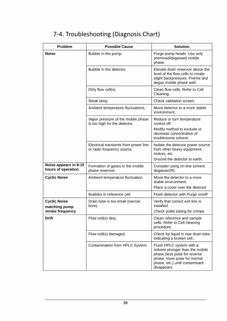
7-4. Troubleshooting (Diagnosis Chart)
Problem Possible Cause Solution
Noise Bubble in the pump. Purge pump heads. Use only premixed/degassed mobile phase.
Bubble in the detector. Elevate drain reservoir above the level of the flow cells to create slight backpressure. Premix and degas mobile phase well.
Dirty flow cell(s). Clean flow cells. Refer to Cell Cleaning.
Weak lamp. Check validation screen.
Ambient temperature fluctuations. Move detector to a more stable environment.
Vapor pressure of the mobile phase is too high for the detector.
Reduce or turn temperature control off.
Modify method to exclude or decrease concentration of troublesome solvent.
Electrical transients from power line or radio frequency source.
Isolate the detector power source from other heavy equipment, motors, etc.
Ground the detector to earth.
Noise appears in 8-10 hours of operation.
Formation of gases in the mobile phase reservoir.
Consider using on-line solvent degasser(R).
Cyclic Noise Ambient temperature fluctuation. Move the detector to a more stable environment.
Place a cover over the detector
Bubbles in reference cell. Flush detector with Purge on/off
Cyclic Noise
matching pump stroke frequency
Drain tube is too small (narrow bore).
Verify that correct exit line is installed.
Check outlet tubing for crimps
Drift Flow cell(s) dirty. Clean reference and sample cells. Refer to Cell cleaning procedure.
Flow cell(s) damaged. Check for liquid in rear drain tube indicating a broken cell..
Contamination from HPLC System. Flush HPLC system with a solvent stronger than the mobile phase (less polar for reverse phase, more polar for normal phase, etc.) until contaminant disappears.

40
Problem Possible Cause Solution
Drift
(continued)
Contaminated or non-HPLC grade solvents.
Prepare fresh mobile phase (premixed/degassed)
Vapor pressure of mobile phase is too high for operating temperature causing bubble formation in reference cell.
Reduce or turn temperature control off.
Modify method to exclude or decrease concentration of troublesome solvent.
Tetrahydrofuran (THF) in the mobile phase will oxidize in the reference cell.
Add an antioxidant to stabilize the THF, if compatible with other chromatographic requirements.
Allow >2 hours stabilization time for oxidation in reference cell to reach a steady state condition.
Baseline drift occurs in few hours of start.
Reference cell solvent has aged and deteriorated.
Flush reference cell with mobile phase.
Baseline will not zero Sample and reference cells do not contain identical solutions.
Flush sample and reference cells with mobile phase.
Reference cell contains air bubbles. Flush sample and reference cells with mobile phase.
Flow cell(s) dirty. Clean flow cell. Refer to Cell Cleaning procedure.
Flow cell(s) damaged. Check for liquid in drain tube indicating a broken cell.
Deteriorating lamp or lamp out of adjustment.
Check validation screen.
Intensity Alarm Flow cell(s) is dirty. Clean flow cell. Refer to Cell cleaning procedure.
Lamp is burned out.
Flow cell(s) is empty. Fill with the eluent.
41
Appendix. Miscibility Chart of Solvents
Acetic Acid
Acetonitrile
Chloroform
Cyclohexane X
Methylene Chloride X = Immiscible
Dimethyl Formamide X
Dioxane
Ethyl Ether
Hexane X X
Methanol X X
Methyl t-Butyl Ether
Trimethylpentane X X X
Pentane X X X
Propanol-2
Tetrahydrofuran
Water X X X X X X X X

ERC Inc.
A part of IDEX Health&Science LLC,
5-8-6 Nishi-Aoki, Kawaguchi, Saitama 332-0035, Japan
Phone: Japan (81) 48-240-5750
Facsimile: Japan (81) 48-259-0715
URL: http://www.idex-hs.com