reflective cracking of flexible pavements phase i and ii
TRANSCRIPT
NDOT Research Report
Report No. 080-07-803
Reflective Cracking of Flexible Pavements
Phase I and II Final Recommendations
February 2008
Nevada Department of Transportation
1263 South Stewart Street
Carson City, NV 89712
Disclaimer
This work was sponsored by the Nevada Department of Transportation. The contents of
this report reflect the views of the authors, who are responsible for the facts and the
accuracy of the data presented herein. The contents do not necessarily reflect the official
views or policies of the State of Nevada at the time of publication. This report does not
constitute a standard, specification, or regulation.
REFLECTIVE CRACKING OF FLEXIBLE PAVEMENTS PHASE I AND II FINAL RECOMMENDATIONS NEVADA DEPARTMENT OF TRANSPORATION Materials Division 1263 South Stewart Street Carson City, Nevada 89712 Research Report No. 13JF-1 February, 2008 UNIVERSITY OF NEVADA RENO Pavements/Materials Program Department of Civil and Environmental Engineering College of Engineering University of Nevada Reno, Nevada 89557

REFLECTIVE CRACKING OF FLEXIBLE PAVEMENTS
PHASE I AND II RECOMMENDATIONS
By
Elie Y. Hajj
Peter E. Sebaaly
Luis Loria
Pavements/Materials Program Department of Civil and Environmental Engineering
College of Engineering University of Nevada Reno, Nevada 89557
February, 2008

i
EXECUTIVE SUMMARY This report summarizes all the findings and recommendations from the Phase I and Phase II of the Nevada DOT study initiated in 2006 to mitigate reflective cracking in HMA overlays. Based on the analysis of the various findings it was recommended to further evaluate the stress relief course as a reflective cracking mitigation technique under Nevada’s conditions. It should be noted that the stress relief course used by NDOT was not specifically designed or checked for its reflective cracking resistance and only consisted of a 1-inch of the typical Type II (1” max size) dense graded HMA mix placed between the existing HMA and the overlay. This NDOT study revealed promising performance for the stress relief course when specifically designed to resist reflective cracking. Additionally, for a good overall performance, the stress relief course needs to be coupled with an overlay mix with a good resistance to reflective cracking. Current state highway agencies’ specifications for stress relief courses were reviewed and are summarized in this report. The review revealed specifications for stress relief courses in six different states. Four of those states: Arizona, California, Florida, and Massachusetts, specify an asphalt-rubber stress absorbing membrane interlayer (SAMI) which consists of an application of asphalt rubber binder followed by an application of aggregate. Texas DOT specifies a Crack Attenuating Mixture (CAM) which consists of an HMA mix designed according to the Superpave design procedure to a target air void of 2% at 50 gyrations along with criteria for the Hamburg Wheel and the TTI Overlay tests. The Utah DOT specifies a reflective cracking relief bituminous mixture which meets the general requirements specified for an HMA mixture except the mix is designed to a target air void of 0.5-2.5% at 50 design gyrations along with criteria for VMA, Hveem stability, and flexural beam fatigue testing at optimum binder content. Based on the limited success of stress relief courses in Nevada and the review of the states’ specifications for stress relief courses it is recommended to conduct an extensive laboratory evaluation for the Texas DOT and the UTAH DOT SRC designs using Nevada’s materials during 2008. The results of the laboratory evaluation will be used to make recommendations for field evaluation during 2009. The overlay thickness will be designed using the Rubber Pavements Association Overlay Design Model. Field mixtures from the SRC and overlay mixes will be collected during construction from behind the paver and evaluated in terms of their dynamic modulus, fatigue resistance, rutting resistance using the RLT, thermal cracking resistance using the TSRST, reflective cracking resistance using the TTI Upgraded Overlay tester, and moisture sensitivity. The performance of the field test sections will be monitored and field cores will be sampled for evaluation in the TTI Overlay Tester. Based on the laboratory evaluation and the field performance the specifications for reflective cracking resistance will be adjusted and the most effective technique will be selected.

ii
TABLE OF CONTENTS
EXECUTIVE SUMMARY ............................................................................................................. i TABLE OF CONTENTS ................................................................................................................ ii 1.0 INTRODUCTION ............................................................................................................... 1 2.0 SUMMARY OF PHASE I ................................................................................................... 1
2.0.1 Findings.............................................................................................................................. 1 2.0.2 Recommendations .............................................................................................................. 3
3.0 SYMMARY OF PHASE II ................................................................................................. 4 3.0.1 Analysis Models................................................................................................................. 4
3.0.1.a Findings .................................................................................................................. 4 3.0.1.b Recommendations ................................................................................................. 6
3.0.2 Laboratory Tests ................................................................................................................ 7 3.0.2.a Findings .................................................................................................................. 7 3.0.2.b Recommendations ............................................................................................... 11
4.0 OVERALL RECOMMENDATIONS ............................................................................... 11 5.0 REVIEW OF STRESS RELIEF COURSES SPECIFICATIONS .................................... 11
5.0.1 Arizona Department of Transportation ............................................................................ 11 5.0.1.a Asphalt Rubber ................................................................................................... 11 5.0.1.b Mineral Aggregates ............................................................................................. 12 5.0.1.c Construction Requirements ............................................................................... 12
5.0.2 California Department of Transportation ......................................................................... 13 5.0.2.a Asphalt Rubber ................................................................................................... 14 5.0.2.b Mineral Aggregates ............................................................................................. 14 5.0.2.c Construction Requirements ............................................................................... 14
5.0.3 Florida Department of Transportation ............................................................................. 15 5.0.3.a Asphalt Rubber ................................................................................................... 15 5.0.3.b Mineral Aggregates ............................................................................................. 17 5.0.3.c Construction Requirements ............................................................................... 17
5.0.4 Iowa Department of Transportation ................................................................................. 17 5.0.5 Massachusetts Department of Transportation .................................................................. 18
5.0.5.a Asphalt Rubber ................................................................................................... 18 5.0.5.b Mineral Aggregates ............................................................................................. 19 5.0.5.c Construction Requirements ............................................................................... 19
5.0.6 Texas Department of Transportation ............................................................................... 19 5.0.6.a Asphalt Binder .................................................................................................... 19 5.0.6.b Mineral Aggregates ............................................................................................. 20 5.0.6.c Tack Coat ............................................................................................................. 20 5.0.6.d Mixture Design .................................................................................................... 20 5.0.6.e Construction Requirements ................................................................................... 21
5.0.7 Utah Department of Transportation ................................................................................. 22 5.0.7.a Asphalt Binder .................................................................................................... 23 5.0.7.b Blended Aggregate .............................................................................................. 23 5.0.7.c Mixture Design .................................................................................................... 23 5.0.7.d Construction Requirements ............................................................................... 24

iii
6.0 PRPOPOSED PLAN FOR PHASE III .............................................................................. 24 7.0 REFERENCES .................................................................................................................. 26

1
1.0 INTRODUCTION
In 2006, the Nevada DOT initiated a three-phase research study to identify the promising techniques to mitigate reflective cracking in HMA overlays: a) Phase I: Review of literature and the performance of the various techniques in Nevada, b) Phase II: Identify analysis models and laboratory tests, and c) Phase III: field verification of the selected techniques. This report summarizes the findings of Phase I and Phase II of this research and presents the recommendations for Phase III. 2.0 SUMMARY OF PHASE I 2.0.1 Findings The literature review of the current and previous efforts outside Nevada on the mitigation of reflective cracking in HMA overlays are summarized in Table 1. Table 1 Summary of Literature Review.
Treatment Description Performance Cold in-place recycling
Remove and mill the upper layers of the existing pavement with specialized recycling equipment then mix with virgin materials to produce a strong flexible base course.
Promising performance for roads with up to 13,000 ADT and 200,000 annual equivalent single axle loads.
Glassgrid Geosynthetic material consisting of connected parallel sets of intersecting ribs with openings of sufficient size.
Benefits in retarding or preventing reflective cracking are not clear. Field performance has varied from excellent to very poor. Concerns when used on rough surfaces.
Fabric interlayer Geosynthetic comprised solely of textiles. A paving fabric interlayer provides the generally acknowledged functions of a stress-absorbing interlayer and a waterproofing membrane. The stress-related performance has been easily verified by the observed reductions of cracking in pavement overlays.
Effective when used for load-related fatigue distress. It did not performed well when used to delay or retard thermal cracking. Optimum performance highly associated with proper construction procedures. The key factor is proper tack-coat installation. In general, overlays reinforced with fabrics have shown better performance than unreinforced overlays under same conditions.
Asphalt rubber interlayer + thin overlay (about 1.5”)
Asphalt rubber chip seal overlaid with conventional dense graded HMA or gap graded HMA.
Reduce and/or delay reflective cracking for a period of 5 years.
Stress absorbing membrane interlayer
A thin layer placed between an underlying pavement and an HMA overlay for the purpose of dissipating movements and stresses at a crack in the underlying pavement before they create stresses in the overlay. SAMIs consist of a spray application of rubber or polymer-modified asphalt as the stress-relieving material, followed by placing and seating aggregate chips.
Successful in reducing the rate of reflective cracking.
Crumb rubber overlay
Produced by adding ground tire rubber to HMA using the wet process.
Ranged from successful to devastating failures depending on percent of crumb rubber in mix.

2
The general results of the review of the long-term field performance of NDOT projects with different techniques to reduce the impact of reflective cracking on HMA overlays are summarized in Table 2. It should be noted that all treatments had either 0.375” or 0.75” open graded friction course on top. Table 2 Summary of NDOT Reflective Cracking Mitigation Techniques Review.
Treatment Description Application Conditions Performance Traffic Pre-rehabilitation
Pavement Condition Cold in-place recycling (CIR)
CIR of minimum top 2.0” of existing HMA materials and overlaying it with a minimum of 2.5” dense graded HMA mixture.
Up to 14,000 AADT.
No severe alligator cracking.
Stopped reflective cracking for 5 years after construction
Reinforced fabric (RF)
Cold milling 2.0” of existing HMA layer, placing fiberglass yarns, and overlaying with 2.0” Type II (1 inch maximum size) dense graded HMA.
Between 1,000 and 10,000 AADT.
No severe alligator cracking.
Retarded reflective cracking for at least 3 years after construction and reduced the rate of reflected transverse cracks 5 years after construction.
Stress relief course (SRC)
Cold milling 2.0” of existing HMA layer, placing a 1” stress relief course and overlaying with 2.0” Type II (1” max size) dense graded HMA.
Up to 40,000 AADT.
NA Stopped reflective cracking for 3 years after construction. Rate of reflected transverse cracks accelerated 5 years after construction.
Mill and overlay (MOL)
Cold milling 1.0” of existing HMA pavement and overlaying it by 1.0” HMA mixture manufactured with an AC-10 asphalt binder.
Up to 40,000 AADT.
NA Reflected fatigue and transverse cracks 1 to 2 years after construction.
Cold milling 1.0” of existing HMA pavement and overlaying it by 1.0” HMA mixture manufactured with an AC-20P asphalt binder.
Up to 4,000 AADT.
NA Stopped reflective cracking for 3 years after construction. Minor reflected transverse cracks 5 years after construction.
Cold milling 1.5” of existing HMA pavement and overlaying it by 1.5” HMA mixture manufactured with an AC-20P asphalt binder. (*)
Up to 2,000 AADT.
NA Stopped reflective cracking for 3 years after construction. Minor reflected transverse cracks 5 years after construction. (*)
* This treatment was placed on pavements with a condition worse than the condition of the pavements where the other two mill and overlay treatments were applied. In general, the long-term effectiveness of the treatments experienced by NDOT was significantly hampered by the existence of severe alligator cracking on the projects prior to the application of these treatments. Therefore, it is recommended that projects experiencing severe alligator cracking as classified by the NDOT pavement distress manual should be subjected to either re-construction or full depth reclamation.

3
The general results of the review of the long-term field performance of the techniques used by Washoe County (WCo), Nevada to mitigate reflective cracking in asphalt overlays are summarized in Table 3. The Washoe County experiences were limited to varying overlay thickness with either nonwoven geotextile fabrics, Petromat, or no fabric placed over the original construction or reconstruction sections prior to the overlay. Table 3 Summary of WCo Reflective Cracking Mitigation Techniques Review. Treatment Description Performance
NF-1.5 No Fabric + 1.5” HMA overlay Retarded reflective cracking for 1 to 3 years after construction.
NF-2.0 No Fabric + 2.0” HMA overlay Retarded reflective cracking for 1 to 3 years after construction.
NF-2.5 No Fabric + 2.5” HMA overlay Retarded reflective cracking for 1 to 5 years after construction.
F-2.0 Non-woven Geotextile Fabric + 2.0” HMA overlay
Retarded reflective cracking for 1 to 5 years after construction.
F-2.0s Non-woven Geotextile Fabric + 2.0”
HMA overlay + slurry seal some years prior treatment application
Retarded reflective cracking for 3 to 5 years after construction with some sections showing reflective cracking within the first year after construction.
P-2.0 Petromat + 2.0” HMA overlay
Retarded reflective cracking for 1 to 5 years after construction. Most of the sections exhibited reflective cracking, either fatigue or longitudinal and transverse cracking at the end of the 5 year analysis period.
P-2.0s Petromat + 2.0” HMA overlay +
slurry seal some years prior treatment application
Retarded reflective cracking for 1 to 5 years after construction on half of the sections and for at least 5 years on the remaining half of the sections. The sections did not develop fatigue cracking during the 5 year analysis period.
2.0.2 Recommendations The research effort documented in the Phase I of the study was directed toward identifying an effective method to eliminate the propagation of the cracks from the old surface layer through the new HMA overlay. Several techniques showed promising results but none of the reviewed methods was able to completely stop reflective cracking. Even though, under Nevada’s conditions the cold in-place recycling of a minimum 2.0 inches and overlaying with a minimum 2.5 inches of dense grade HMA mix was proven to be effective in stopping reflective cracking for at least 5 years, it may not be the most cost effective rehabilitation technique for every highway pavement. Therefore, based on the literature and performance reviews, it is recommended to further investigate the stress relief course technique. It should be noted that the stress relief course experienced by NDOT was not specifically designed or checked for its reflective cracking resistance and only consisted of a 1-inch of the typical Type II (1” max size) dense graded HMA mix placed between the existing HMA and the overlay. This study revealed promising

4
performance for the stress relief course when specifically designed to resist reflective cracking. Additionally, for a good overall performance, the stress relief course needs to be coupled with an overlay mix with good resistance to reflective cracking.
3.0 SYMMARY OF PHASE II
The research effort of Phase II was directed toward identifying an analytical model(s) and laboratory or field test(s) that can be used to predict the resistance of HMA overlays to reflective cracking and predict their long-term performance.
3.0.1 Analysis Models
Based on the review of the currently available analytical models to predict the resistance of HMA overlays to reflective cracking, three design methods were identified and summarized.
• Virginia Tech Simplified Overlay Design Model • Rubber Pavements Association (RPA) Overlay Design Model • The New AASHTO model for Reflective Cracking
3.0.1.a Findings The Virginia Tech Simplified Overlay Design Model (1) consist of a simple regression equation for predicting the number of cycles in ESALs (Wt80) to produce the crack reflection to the pavement surface as a function of: thickness and resilient modulus of HMA overlay (Hoverlay [mm], Eoverlay [MPa]), thickness and resilient modulus of existing HMA layer (HHMA [mm], EHMA [MPa]), thickness and resilient modulus of base layer (Hbase [mm], Ebase [MPa]), and resilient modulus of subgrade layer (Esubgrade [MPa]). The total number of load repetitions is defined as the sum of the number of load repetitions for crack initiation and the number of load repetitions for crack propagation. log 255 2.08 45.3 8.73 1.34 6.93 1.49 (1) Equation 1 clearly shows that the overlay mix with a higher stiffness will withstand a higher number of load repetitions. However, it should be noted that a stiffer mix may be brittle thus more susceptible to reflective cracking. The Rubber Pavements Association Overlay Design Model (2) consists of a mechanistic relationships and statistically based equations for designing HMA overlays on top of HMA pavements. The proposed models are based on a finite element model that closely approximates actual field phenomena of dense-graded HMA and gap-graded asphalt rubber-AR (wet process) overlay mixes. However, other HMA mixes used for overlays may also be calibrated and used through the proposed method using the relevant mix

5
properties. The overlay design program is available from the Rubber Pavements Association in the form of an EXCEL spreadsheet that estimates the thickness of a PG70-10 or an AR HMA overlay mix for the specified level of reflective cracking for a wide range of traffic loading. The expected design level of cracking, the thicknesses and the elastic moduli of the existing pavement layers, and the modulus of the HMA overlay are inputs for the EXCEL spreadsheet. The moduli may be backcalculated or determined in any reasonable manner, as long as they represent the in situ conditions in the field. The reflective cracking models incorporated in the new AASHTO Mechanistic-Empirical Pavement Design Guide (MEPDG) are strictly based on empirical observations without any rigorous mechanistic-empirical analysis (3). The empirical models consider the development of distresses in the overlay as well as the continuation of damage in the existing pavement structure. The proposed MEPDG overlay design procedure allows for two types of reflective cracks: a) reflective cracks that exist on the surface prior to overlay placement and b) those that develop in the existing surface after overlay placement. An overlay design was conducted for three different HMA overlay mixes using the three identified overlay design methods. The overlay mixes were manufactured using different aggregate gradations from the Sloan pit in Southern Nevada and a PG76-22NV polymer modified asphalt binder. The overlay was designed for 7,075,000 ESALs over the 20 years analysis period. Table 4 shows the material properties of the various pavement layers used in the analysis. It should be noted that the fatigue characteristics of the various mixes can only be incorporated in the Rubber Pavements Association Overlay Design Method. Table 5 shows the required overlay thicknesses for the design ESALs according to all three design methods. The data in Table 5 show that for the same design ESALs, a thicker overlay thickness is required for the T2C mix followed by the CT mix followed by the NRM mix when designing using the Virginia Tech method. On the other hand, the opposite was found when designing using the Rubber Pavements Association method where a thinner overlay thickness is required for the T2C mix followed by the CT mix followed by the NRM mix to reach the same selected percentage of cracking. The AASHTO MEPDG design method resulted in a 12 inch overlay thickness to reach 100% reflected cracking after 20 years design period regardless of the type of the overlay mix. In a summary when only the stiffness of the overlay mix is considered (i.e., Virginia Tech method), a thinner overlay thickness was found for the stiffer mix whereas, when both the stiffness and the fatigue characteristic of the mix are considered (i.e., RPA method), the overlay thickness depended on the interaction between the two material properties.

6
Table 4 Pavement Layers Material Properties.
Layers Thickness (inch)
Modulus at 70°F (ksi) Fatigue characteristics*
HMA overlay
NDOT T2C --# 790 1.3740 101 . 1 .
CT --# 1,045 6.5815 101 . 1 .
NRM --# 1,375 6.8745 101 . 1 .
Cracked HMA 4.0 360 N.A.
Unbound base 10.0 30 N.A.
Subgrade -- 12 N.A.
*Nf is the number of repetitions to failure, ε is the flexural strain in microns # to be designed according to all three reflective cracking design methods Table 5 Overlay Design Thicknesses for 20 years Design Period.
HMA overlay mix
Overlay thickness (inches)
Virginia Tech
Rubber Pavements Association AASHTO MEPDG (100% reflected cracks) % reflected cracking
0% 2% 5% 15% NDOT T2C 4.50 3.60 2.40 2.00 0.75 12.00 CT 4.00 4.90 4.00 3.00 1.00 12.00 NRM 3.25 15.25 12.50 9.25 3.25 12.00 3.0.1.b Recommendations The assessment of the three identified design models illustrated the following advantages for Rubber Pavements Association method:
• Consider the overlay mixture material properties in terms of the stiffness as determined by the dynamic modulus test and the fatigue characteristic as determined by the flexural beam fatigue test at constant strains and various temperatures.
• Allow for the selection of the desired percent of cracking at the end of the design life.
7
Consequently, it is recommended to validate the RPA Overlay Design Model under Nevada’s mixes and conditions. 3.0.2 Laboratory Tests This task reviewed the laboratory tests that have been used to evaluate the resistance of HMA mixtures to reflective cracking. Laboratory tests are typically used to evaluate the resistance of the HMA mixtures to reflective cracking during the mix design stage. 3.0.2.a Findings Table 6 summarizes the review of the various laboratory test methods used to evaluate the resistance of HMA mixtures to reflective cracking. None of the reviewed laboratory test methods has undergone field validation except the TTI Overlay Tester which showed consistency between the mixtures’ test results and their corresponding field performance. The Overlay Tester was able to differentiate between the poor crack resistant and the good crack resistant HMA mixes. Additionally, the overlay tester results on field cores taken from different highways showed that asphalt mixtures performed very well when the reflective cracking life (from the overlay tester) is larger than 300. Thus, the TTI researchers proposed the preliminary pass/fail criterion on reflective cracking resistance to be 300 cycles at 77ºF (25ºC) and 0.025 inch (0.64 mm) opening displacement. When a rich bottom layer is used, it was proposed that the reflective cracking life in the overlay tester should be at least 750 cycles.

8
Table 6 Summary of Laboratory Testing Methods for Reflective Cracking.
Testing device
Type of test
Failure mode
Geometry of specimens Type of load Test results Findings Schematic
Cracow University of Technology, Poland (4)
Bending or Shearing
I & II Beams: 12×3×3 inch
- Static bending load: loading rate 0.47 in/min.
- Repeated haversine bending load: 5 Hz.
- Static shearing: loading rate 4×10⁻² in/min.
- Static bending: cracking time, max force & bending strength.
- Dynamic bending: number of repetitions.
- Static shear: max shear force & stress.
The bending test under repeated load indicates that HMA overlays reinforced with geotextiles exhibited a greater resistance to the crack development. The shearing test showed that the presence of a geotextile diminished more than two times the adhesion between the asphalt layers.
Technion-Israel Institute of Technology, Israel (5)
Wheel tracking device
I Beams: 28×4×4 inch
- Cyclic wheel load. - Number of wheel loading repetitions to failure.
- Crack length versus number of repetitions and testing time.
The evaluated geotextile fabric had a resistance to reflective cracking 4 times greater than other techniques.
Geo-materials Laboratory, ENTPE, France - Fissurometer (6)
Uniaxial tension
I Slabs - Static: rate of 0.05 to 0.22 in/hr.
- Cyclic uniaxial.
- Measure of energy transmitted by an ultrasonic wave train.
A comparision between the fissurometer and field results from different cracking mitigation techniques showed that the device classified them in reverse order (opposite to field performance). It might be because the fissurometer only simulates thermal shrinkage.
Technical University of Vienna, Austria - Wedge splitting (7)
Splitting I Cubical or prismatic
- Static: loading rate 0.05 in/min.
- Horizontal force versus displacement.
- Maximum vertical force versus temperature.
- Fracture energy versus temperature.
The researchers concluded that the maximum splitting force is not an appropriate parameter to differentiate between HMA mixes since two different mixes can have the same maximum splitting force and different fracture behavior. The specific fracture energy was recommended as a more reliable testing parameter to differentiate between mixes.

Ta
Laof RoFra
UnCoDuaccsimwhtraUnIlliU.
AeTeal IAT(11FloAtUnU.
able 6 Summary
Testing device
Type test
aboratory Public
oads, ance (8)
Biaxia
niversity ollege of ublin - celerated mulative heel acking (9)
Wheel trackindevice
niversity of inois, S.A (10)
Uniaxitension
eronautical echnologicInstitute,
TI, Brazil 1)
Bendinor Shearin
orida lantic
niversity, S.A (12)
Bendin(singlepoint oloading
y of Laboratory
of t
Failure mode
Geosp
l I & II Bea24×inch
ng I & II Bea
- B5.5×inch- To5.5×inch
ial n
I HMon tPCC6×9inch
ng
ng
I & II Bea18×
ng e of g)
I Bea18×inch
Testing Method
ometry of ecimens Typ
ams: 2.8×2.8
h
- Cyclicload: 1
- Static hload: 0
ams Bottom-up ×11×2.0 h. op-down ×10.2×2.0 h.
- Cyclic21 cycl
MA layer top of a C slab of 90×2.7 h
- Cyclicload: fr0.0016(triangu
ams: 6×3 inch
- Sinusoloading20 Hz.
ams: 6×7.5
h
- Static- Cyclicload: 2
ds for Reflective
pe of load
vertical Hz. horizontal
0.024 in/hr.
- Cra& le
- Cratime
- Bre wheel load: les/min.
- Numloadvers
- Defslabinchtest
uniaxial frequency 6 in/min ular).
- Straas fcyc
- Cratime
oidal load: g frequency
- Perverscyc
- Tencrac
(Sinusoidal) 2 Hz.
- Thenumto f
- Thenumforto h
- Thenumfor to to
9
e Cracking (con
Test results
ack initiation time ength. ack propagation e & length. eaking time. mber of wheel ding repetitions sus crack length. formation of the bs over the central 8 h throughout the t. ain in HMA overlay function of test les.
ack length versus e
rmanent strain sus number of load les. nsile stress versus ck length. e load value or mber of repetitions first reflected crack. e load value or mber of repetitions crack propagation
half way of overlay. e load value or mber of repetitions crack propagation op of overlay.
ntinued).
Find
Paving fabrics delinitiation time, whHMA mix slows dpropagation.
No tests performe
The Interlayer StreComposite (ISACbetter performanccommercial produtested in the test d
The HMA overlaygeogrid had a life higher than an HMwithout reinforcem
At the same load rhaving geogrids embottom showed bereflection crackingspecimens in whicwas simply attachwith a tack coat. Awas found that geoat mid-height was than geogrid embebottom of overlay
dings
lays the crack hile the rich down the crack
d.
ess Absorbing ) had a much e than other
ucts when was device.
y reinforced with up to 6 times
MA overlay ment.
ratio, the slabs mbedded at the etter resistance to g compared to ch the geogrids ed to the bottom Additionally, it ogrid embedded more effective
edded at the .
Schem
Bottom-up cracking
N.A
matic
Top-down cracking
A.

10
Table 6 Summary of Laboratory Testing Methods for Reflective Cracking (continued).
Testing device
Type of test
Failure mode
Geometry of specimens Type of load Test results Findings Schematic
Polytechnic University of Madrid, Spain - Wheel Reflective Cracking device (13)
Biaxial I & II Beams: 12×12×2.4 inch
- Cyclic wheel load. - Static traction force: 0.001 to 50 µm/hr.
- Vertical length of the crack with time.
- Vertical displacement with time
- Relative movement between crack edges.
Three treatments were studied: HMA overlay without geotextile, and reinforced with two different types of geotextile The overlay without reinforcing showed the worst performance.
Regional Laboratory of Pont et Chausses, France - MEFISTO (14)
Biaxial I & II Beams: 2×2×26 inch
- Static (horizontal load)
- Cyclic (vertical load): sinusoidal 10 Hz.
- Number of repetitions versus vertical force or dissipated energy.
- Number of repetitions versus crack length.
No tests were performed.
Texas Transportation Institute Overlay Tester (15)
Biaxial I & II Cores: 6-inch diameter Beams: 6×3×2 inch
- Triangular cyclic load: 10 seconds/cycle.
- Number of repetitions versus crack length.
- Number of repetitions versus testing time.
The major findings of the extensive experimental work indicated that a very good repeatability for the device. It was found to be sensitive to the testing temperature, opening displacement, asphalt binder content and grade, and air voids. Also it showed consistency between the mixtures’ test results and their corresponding field performance. The pass/fail criterion on reflective cracking resistance is 300 cycles at 77 ºF (25 ºC) and 0.025 in (0.64 mm) opening displacement. When a rich bottom layer is used, the reflective cracking life in the overlay tester should be at least 750 cycles.

11
3.0.2.b Recommendations It is recommended to use the TTI Upgraded Overlay Tester to evaluate typical NDOT mixtures along with their actual field performance to develop performance criteria that can be used at the design stage of the overlay mixture. 4.0 OVERALL RECOMMENDATIONS Based on the findings of the Phase I and Phase II of the study it is recommended to evaluate the stress relief courses under Nevada’s conditions. Therefore the following recommendations are made:
• Review the current state highway agencies’ specifications for stress relief courses (SRC).
• Use the TTI Upgraded Overlay Tester to evaluate mixtures in the Laboratory for reflective cracking resistance.
• Use the Rubber Pavements Association Overlay Design Model to design the require overlay thickness.
5.0 REVIEW OF STRESS RELIEF COURSES SPECIFICATIONS 5.0.1 Arizona Department of Transportation The Arizona Department of Transportation (ADOT) defines the Stress absorbing membrane interlayer (SAMI) as a furnishing of tack coat followed by an asphalt-rubber film and a cover material of mineral aggregate (16). 5.0.1.a Asphalt Rubber The asphalt rubber shall be a mixture of asphalt cement and rubber. The asphalt binder should have a performance grade (PG) conforming AASHTO Provisional Standard MP1. The rubber gradation for the SAMI shall meet the requirements shown in Table 7 when tested in accordance with Arizona Test Method 714. Table 7 ADOT Rubber Gradation for SAMI (Type A).
Sieve size Percent Passing No. 8 100
No. 10 95-100 No. 16 0-10 No. 30 -- No. 50 --
No. 200 --

12
The rubber shall have a specific gravity of 1.15 ± 0.05. Additionally, the rubber shall be free of wire or other contaminating materials and shall contain not more than 0.1 percent fabric. Calcium carbonate, up to 4 percent by weight of the granulated rubber, may be added to prevent the particles from sticking together. The asphalt rubber shall contain a minimum of 20 percent ground rubber by the weight of the asphalt cement and shall conform to the requirements in Table 8. Table 8 Required Properties for the Asphalt-rubber.
Property Specifications Type 1 Type 2 Type 3
Grade of base asphalt cement PG 64-16 PG 58-22 PG 52-28 Rotational viscosity: 350 °F, Pa.s 1.5 – 4.0 1.5 – 4.0 1.5 – 4.0 Penetration at 4°C, 200 g, 60 s (ASTM D5), minimum 10 15 25 Softening point (ASTM D 36), °F, minimum 135 130 125 Resilience, 77 °F (ASTM D 5329), % minimum 30 25 15 5.0.1.b Mineral Aggregates Aggregates for cover material shall be of clean sand, gravel or crushed rock and shall be free from lumps or balls of clay and shall not contain calcareous or clay coatings, caliche, synthetic materials, organic matter or foreign substances. The aggregates shall meet the requirements in Table 9. Table 9 Required Properties for the Mineral Aggregates.
Property Test Method Specifications Los on Abrasion AASHTO T96 9% for 100 revolutions
40% for 500 revolutions % of carbonates Arizona Test Method 238 Max. 30 % fractured coarse aggregate particles Arizona Test Method 212 Min. 70 Flakiness Index Arizona Test Method 233 Max. 25 Bulk Oven Dry Specific Gravity Arizona Test Method 210 2.30 – 2.85 Gradation Arizona Test Method 201 Sieve Size % Passing
3/8 inch 100 ¼ inch 0-15 No. 8 0-5
No. 200 0-2 5.0.1.c Construction Requirements The asphalt rubber shall be placed on a previously cleaned surface. After cleaning and prior to the application of the SAMI, the existing pavement surface shall be treated with a

13
tack coat conforming to the requirements of Subsection 404-3.12 of the specifications and under the following conditions.
• Ambient air temperature and pavement surface temperature are both above 65°F. • Pavement is dry. • Wind conditions are such that a satisfactory SAMI can be achieved. • All construction equipment such as asphalt rubber distributor, aggregate spreader,
haul trucks with aggregate material, and rollers are in position and ready to start placement operations.
Distributor trucks shall be so designed, equipped, maintained and operated that bituminous material at even heat may be applied uniformly on variable widths of surface up to 15 feet at readily determined and controlled rates of 0.03 to one gallon per square yard, with uniform pressure, and with an allowable transverse variation from any specified rate not to exceed 10 percent or 0.02 gallons per square yard, whichever is less. The maximum deviation from the specified rate shall not exceed 0.05 gallons per square yard. The hot asphalt-rubber binder shall be applied at the rate of approximately 0.55 ± 0.05 gallons per square yard (based on a unit weight of 7.75 pounds per gallon of hot asphalt-rubber). Cover material (aggregate) shall be immediately and uniformly spread over the freshly applied asphalt-rubber at the rate of approximately 0.014 cubic yards per square yard. Cover material shall be precoated with 0.40 to 0.60 percent asphalt cement, by weight of the aggregate, and shall have a minimum temperature of 250 °F at the time of application. Traffic of all types shall be kept off the stress-absorbing membrane until it has had time to set properly. The minimum traffic free period shall be three hours. Sweeping shall be completed and all excess cover material removed prior to the placement of any subsequent layers of asphaltic concrete. If the asphalt-rubber membrane has been subjected to traffic, a tack coat shall be applied at the rate of approximately 0.06 gallons per square yard prior to placement of the asphaltic concrete. 5.0.2 California Department of Transportation The California Department of Transportation (CALTRANS) defines an Asphalt-rubber membrane interlayer (SAMI-R) as an asphalt rubber chip seal that is overlaid with conventional dense graded asphalt mixture (AC) or a gap graded hot mix (RAC-G) (17). SAMI-R is a low modulus (nonstructural) layer that is used to retard and minimize reflective cracking in overlays placed on it, and to minimize further infiltration of surface water through the pavement structure. No fog seal or sand should be applied over a SAMI-R because this could interfere with bonding of the overlay. SAMI-R may be applied to any type of rigid (PCC) or asphalt pavement, and have proved very effective at minimizing reflection of PCC joints.

14
However, according to the Caltrans Maintenance Manual, if the surface irregularities (rutting in AC or faulting of PCC) exceed 12.5 mm then either a leveling course should be placed or grinding and crack filling are required prior to placing SAMI-R. SAMIs are used under corrective maintenance overlays and are a pavement rehabilitation tool. A SAMI-R would not be included as part of new construction. Design of the asphalt rubber binder is the same as for chip seal. Determination of appropriate binder and cover aggregate application rates is also the same. 5.0.2.a Asphalt Rubber Typically the AR-4000 is used as a base asphalt binder. The asphalt rubber shall conform to the requirements in Table 10. Table 10 Laboratory Asphalt Rubber Binder Design Data.
Property Minutes of Reaction 45 minutes
Specifications Limits 45 90 240 360 1,440
Viscosity, Haake at 190°C, Pa.s, (10-3), or cP (*) 2,400 2,800 2,800 2,800 2,100 1,500-4,000
Resilience at 25°C, % Rebound (ASTM D 3407) 27 -- 33 -- 23 18 Minimum
Ring & Ball Softening Point, °C (ASTM D 36) 59.0 59.5 59.5 60.0 58.5 52-74
Cone Pen. at 25°C, 150g, 5 sec., 1/10 mm (ASTM D217) 39 -- 46 -- 50 25-70
(*) The viscosity test shall be conducted using a hand-held Haake viscometer or equivalent. 5.0.2.b Mineral Aggregates The standard chip size for Caltrans asphalt rubber seals is 9.5 mm. The 12.5 mm chips are used by Caltrans only where ADT is less than 5,000 per lane. 5.0.2.c Construction Requirements To construct a chip seal, the hot asphalt rubber binder is sprayed on the roadway surface at a rate determined by the Engineer. The binder is immediately covered with a layer of hot pre-coated chips that must be quickly embedded into the binder by rolling before the membrane cools. Best results are achieved with clean nominal 9.5 to 12.5 mm single-sized chips. Lightweight aggregates may be substituted to minimize windshield breakage by loose chips in areas where traffic is heavy or fast. Pre-coating the aggregate with asphalt cement improves adhesion by removing surface dust and “wetting” the chips. Caltrans requires that the aggregate chips be delivered to
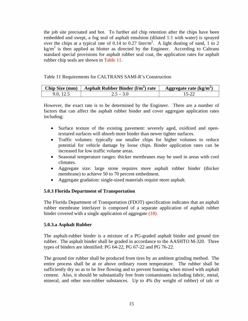
15
the job site precoated and hot. To further aid chip retention after the chips have been embedded and swept, a fog seal of asphalt emulsion (diluted 1:1 with water) is sprayed over the chips at a typical rate of 0.14 to 0.27 liter/m2. A light dusting of sand, 1 to 2 kg/m2 is then applied as blotter as directed by the Engineer. According to Caltrans standard special provisions for asphalt rubber seal coat, the application rates for asphalt rubber chip seals are shown in Table 11. Table 11 Requirements for CALTRANS SAMI-R’s Construction Chip Size (mm) Asphalt Rubber Binder (l/m2) rate Aggregate rate (kg/m2)
9.0, 12.5 2.5 – 3.0 15-22 However, the exact rate is to be determined by the Engineer. There are a number of factors that can affect the asphalt rubber binder and cover aggregate application rates including:
• Surface texture of the existing pavement: severely aged, oxidized and open-textured surfaces will absorb more binder than newer tighter surfaces.
• Traffic volumes: typically use smaller chips for higher volumes to reduce potential for vehicle damage by loose chips. Binder application rates can be increased for low traffic volume areas.
• Seasonal temperature ranges: thicker membranes may be used in areas with cool climates.
• Aggregate size: large stone requires more asphalt rubber binder (thicker membrane) to achieve 50 to 70 percent embedment.
• Aggregate gradation: single-sized materials require more asphalt. 5.0.3 Florida Department of Transportation The Florida Department of Transportation (FDOT) specification indicates that an asphalt rubber membrane interlayer is composed of a separate application of asphalt rubber binder covered with a single application of aggregate (18). 5.0.3.a Asphalt Rubber The asphalt-rubber binder is a mixture of a PG-graded asphalt binder and ground tire rubber. The asphalt binder shall be graded in accordance to the AASHTO M-320. Three types of binders are identified: PG 64-22, PG 67-22 and PG 76-22. The ground tire rubber shall be produced from tires by an ambient grinding method. The entire process shall be at or above ordinary room temperature. The rubber shall be sufficiently dry so as to be free flowing and to prevent foaming when mixed with asphalt cement. Also, it should be substantially free from contaminants including fabric, metal, mineral, and other non-rubber substances. Up to 4% (by weight of rubber) of talc or
16
other inert dusting agent, may be added to prevent sticking and caking of the particles. The physical properties of the ground tire rubber shall meet the following requirements:
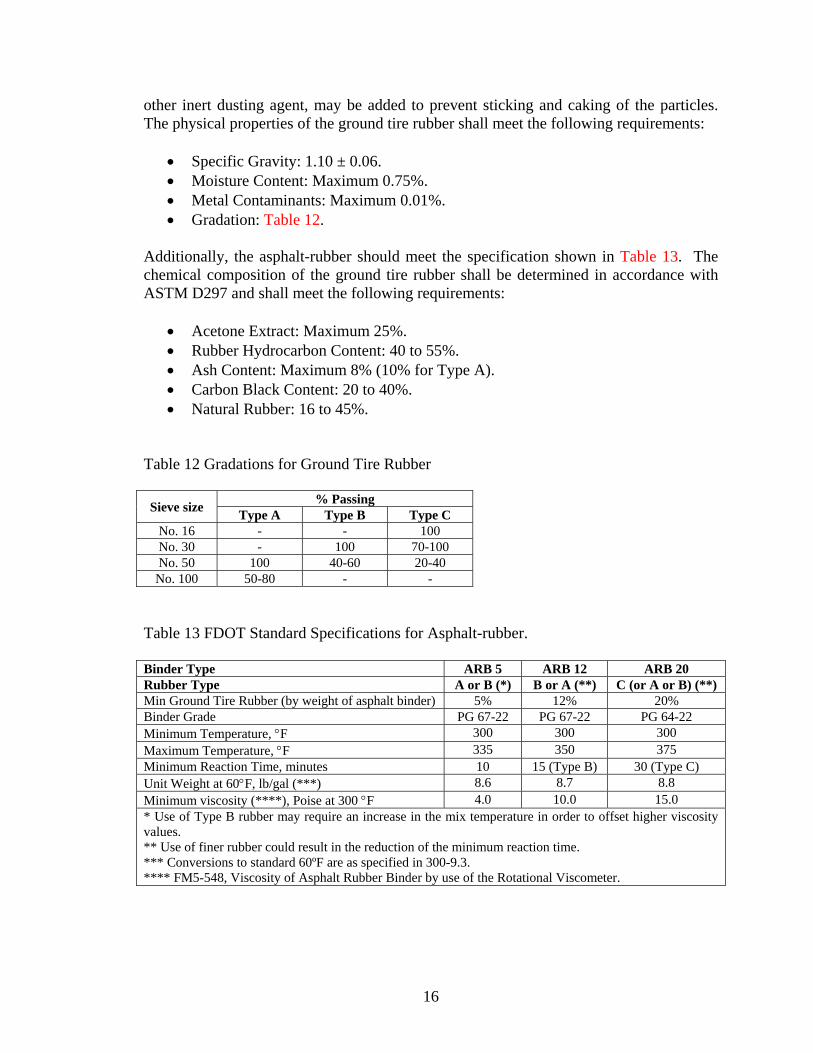
• Specific Gravity: 1.10 ± 0.06. • Moisture Content: Maximum 0.75%. • Metal Contaminants: Maximum 0.01%. • Gradation: Table 12.
Additionally, the asphalt-rubber should meet the specification shown in Table 13. The chemical composition of the ground tire rubber shall be determined in accordance with ASTM D297 and shall meet the following requirements:
• Acetone Extract: Maximum 25%. • Rubber Hydrocarbon Content: 40 to 55%. • Ash Content: Maximum 8% (10% for Type A). • Carbon Black Content: 20 to 40%. • Natural Rubber: 16 to 45%.
Table 12 Gradations for Ground Tire Rubber Sieve size % Passing
Type A Type B Type C No. 16 - - 100 No. 30 - 100 70-100 No. 50 100 40-60 20-40
No. 100 50-80 - - Table 13 FDOT Standard Specifications for Asphalt-rubber. Binder Type ARB 5 ARB 12 ARB 20 Rubber Type A or B (*) B or A (**) C (or A or B) (**) Min Ground Tire Rubber (by weight of asphalt binder) 5% 12% 20% Binder Grade PG 67-22 PG 67-22 PG 64-22 Minimum Temperature, °F 300 300 300 Maximum Temperature, °F 335 350 375 Minimum Reaction Time, minutes 10 15 (Type B) 30 (Type C) Unit Weight at 60°F, lb/gal (***) 8.6 8.7 8.8 Minimum viscosity (****), Poise at 300 °F 4.0 10.0 15.0 * Use of Type B rubber may require an increase in the mix temperature in order to offset higher viscosity values. ** Use of finer rubber could result in the reduction of the minimum reaction time. *** Conversions to standard 60ºF are as specified in 300-9.3. **** FM5-548, Viscosity of Asphalt Rubber Binder by use of the Rotational Viscometer.

17
5.0.3.b Mineral Aggregates The aggregate size No. 6 (0.75 inch aggregate size) shall be used and shall meet the requirements of Section 901 of the FDOT Standard Specifications. 5.0.3.c Construction Requirements The existing pavement should be cleaned prior to the application of the asphalt rubber binder. The asphalt rubber binder should be applied only under the following conditions:
• Air temperature is above 50ºF and rising. • Pavement is absolutely dry. • Wind conditions are such that cooling of the asphalt rubber binder will not be so
rapid as to prevent good bonding of the aggregate. The asphalt rubber binder shall be applied at the rate of 0.6 to 0.8 gal/yd2 or as directed by the Engineer. Immediately after application of the asphalt rubber binder, the cover material (aggregate) should be spread uniformly at a rate of 0.26 and 0.33 ft3/yd2. The application of the asphalt rubber binder and the application of the cover material should not be separated by more than 300 feet, unless approved by the Engineer. In order to ensure maximum embedment of the aggregate, the entire width of the mat should be covered immediately by the traffic rollers. For the first coverage, a minimum of three traffic rollers should be provided in order to accomplish simultaneous rolling in echelon of the entire width of the spread. 5.0.4 Iowa Department of Transportation The Iowa Department of Transportation (IDOT) only specifies SAMI’s for placement under an unbonded Portland cement concrete (PCC). Such SAMI consists of a nominal 1-inch thick HMA layer (19). The asphalt binder shall be a PG58-28. The mixture shall meet the following characteristics:
• 300,000 design ESAL. • 3/8 inch (9.5 mm) nominal aggregate size gradation. • The air voids target is 3.0%. • No maximum film thickness restriction. • No minimum filler/bitumen ratio restriction. • Aggregate shall be Type B with no percent crushed particle requirements and
gradation shall fall below the restricted zone. The only performance test specified to the mixture is the Tensile strength ratio (TSR). The contractor shall run AASHTO T 283 during production. The test results shall satisfy

18
80% TSR when compared to the dry strength of specimens prepared with asphalt binder containing the anti-strip additive. 5.0.5 Massachusetts Department of Transportation The Massachusetts Department of Transportation (MDOT) specifies the SAMI as the application of hot, rubberized asphalt and immediately embedding aggregate therein by spreading and rolling according with these specifications (20). 5.0.5.a Asphalt Rubber The asphalt cement for the asphalt-rubber mixture shall be AC-10 or AC-20. If AC-10 is used, the SAMI shall be overlaid within ten days. The granulated rubber shall be a vulcanize rubber product from the ambient temperature processing of pneumatic tires. The granulated rubber type shall meet the gradation in Table 14. Table 14 MDOT Standard Specifications for Asphalt-Rubber Gradation.
Sieve Percent Passing 2.36 mm 100 2.00 mm 95-100 1.18 mm - 600 µm 0-10 300 µm 0-5
The percent of asphalt-rubber shall be 23 ± 2% by the total weight of asphalt cement plus granulated rubber. The temperature of the asphalt shall be between 347°F and 428°F at the time of addition of the vulcanized rubber. The asphalt and the rubber shall be mixed together in a blender unit and reacted in a distributor for a period of time determined as required by the engineer. The temperature of the rubberized asphalt mixture shall be above 320 °C during the reaction period.
After the reaction between the asphalt and rubber has occurred, the viscosity of the hot rubberized asphalt mixture may be adjusted for spraying and “wetting” of the cover material by the addition of a diluent. The diluent shall comply with the requirements of ASTM D369, Grade #1 fuel oil and shall not exceed 7.5 percent by volume of the hot asphalt rubber mixture.
Viscosities shall be run on each blended load of rubberized asphalt rubber using a Haake field viscometer. One viscosity prior to the induction of the diluent and one after the induction of the diluent blended into the asphalt and rubber mixture. The viscosity of the final product shall be in the range of 2 to 3 Pascal-seconds.
19
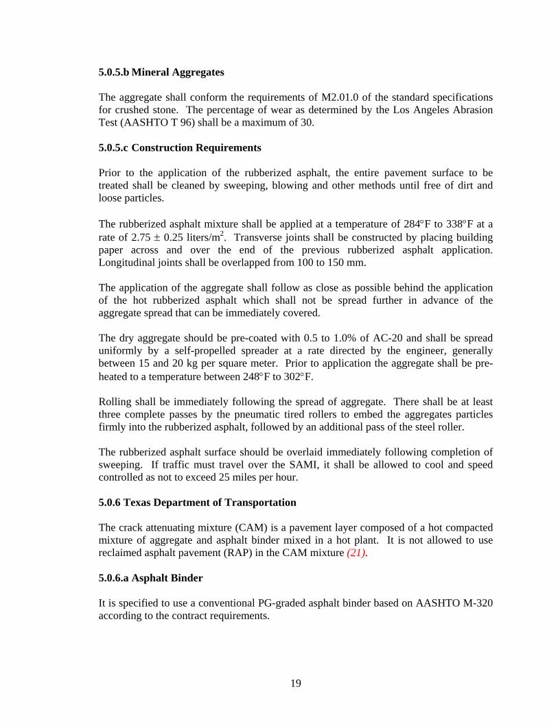
5.0.5.b Mineral Aggregates The aggregate shall conform the requirements of M2.01.0 of the standard specifications for crushed stone. The percentage of wear as determined by the Los Angeles Abrasion Test (AASHTO T 96) shall be a maximum of 30. 5.0.5.c Construction Requirements Prior to the application of the rubberized asphalt, the entire pavement surface to be treated shall be cleaned by sweeping, blowing and other methods until free of dirt and loose particles. The rubberized asphalt mixture shall be applied at a temperature of 284°F to 338°F at a rate of 2.75 ± 0.25 liters/m2. Transverse joints shall be constructed by placing building paper across and over the end of the previous rubberized asphalt application. Longitudinal joints shall be overlapped from 100 to 150 mm. The application of the aggregate shall follow as close as possible behind the application of the hot rubberized asphalt which shall not be spread further in advance of the aggregate spread that can be immediately covered. The dry aggregate should be pre-coated with 0.5 to 1.0% of AC-20 and shall be spread uniformly by a self-propelled spreader at a rate directed by the engineer, generally between 15 and 20 kg per square meter. Prior to application the aggregate shall be pre-heated to a temperature between 248°F to 302°F. Rolling shall be immediately following the spread of aggregate. There shall be at least three complete passes by the pneumatic tired rollers to embed the aggregates particles firmly into the rubberized asphalt, followed by an additional pass of the steel roller. The rubberized asphalt surface should be overlaid immediately following completion of sweeping. If traffic must travel over the SAMI, it shall be allowed to cool and speed controlled as not to exceed 25 miles per hour. 5.0.6 Texas Department of Transportation The crack attenuating mixture (CAM) is a pavement layer composed of a hot compacted mixture of aggregate and asphalt binder mixed in a hot plant. It is not allowed to use reclaimed asphalt pavement (RAP) in the CAM mixture (21). 5.0.6.a Asphalt Binder It is specified to use a conventional PG-graded asphalt binder based on AASHTO M-320 according to the contract requirements.

20
5.0.6.b Mineral Aggregates The mineral aggregate shall meet the properties specified in Table 15. The coarse aggregate stockpiles must have no more than 20% material passing the No. 8 sieve. The fine aggregate consist of manufacture sands. Natural sands are not allowed. Fine aggregate stockpiles must meet the gradation requirements in Table 16. The fine aggregate shall be supplied free from organic impurities. If 10% or more of the fine aggregate stockpile is retained on the No.4 sieve, test the stockpile and verify that it meets the requirements in Table 15 for coarse aggregate angularity and flat and elongated particles.
Table 15 Aggregate Quality Requirements.
Property Test Method Requirement Coarse Aggregate
Deleterious material, %, max Tex-217-F, part I 1.0 Decantation, % max Tex-217-F, part II 1.5 Micro-Deval abrasion, % max Tex-431-A 1
Los Angeles abrasion, % max Tex-410-A 30 Magnesium sulfate soundness, 5 cycles, %, max Tex-411-A 20 Coarse aggregate angularity, 2 crushed faces, %, min Tex-460-A, Part I 952
Flat end elongated particles @5:1, %, max Tex-280-F 10 Fine Aggregate
Linear shrinkage, % max Tex-107-E 3 Combined Aggregate3
Sand equivalent, %, min Tex-203-F 45 1 Not used for acceptance purposes. Used by the engineer as an indicator of the need for further investigation. 2 Only applies to crushed grave. 3 Aggregates, without mineral fillers, or additives, combined as used in the job-mix formula (JMF) Table 16 Gradation Requirements for Fine Aggregate.
Sieve Size % Passing by Weight or Volume 3/8” 100 #8 70-100
#200 0-30 5.0.6.c Tack Coat A base PG-graded binder should be used with a minimum high-temperature grade of PG58. 5.0.6.d Mixture Design The mixture shall be designed according to the Superpave design procedure given in Tex-204-F, Part IV. The target laboratory density should be 98.0% at Ndes = 50. The engineer
21
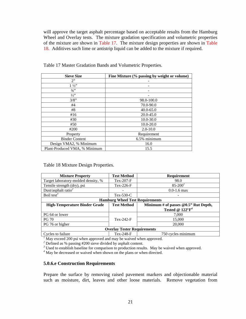
will approve the target asphalt percentage based on acceptable results from the Hamburg Wheel and Overlay tests. The mixture gradation specification and volumetric properties of the mixture are shown in Table 17. The mixture design properties are shown in Table 18. Additives such lime or antistrip liquid can be added to the mixture if required. Table 17 Master Gradation Bands and Volumetric Properties.
Sieve Size Fine Mixture (% passing by weight or volume) 2” -
1 ½” - ¾” - ½” -
3/8” 98.0-100.0 #4 70.0-90.0 #8 40.0-65.0
#16 20.0-45.0 #30 10.0-30.0 #50 10.0-20.0 #200 2.0-10.0
Property Requirement Binder Content 6.5% minimum
Design VMA2, % Minimum 16.0 Plant-Produced VMA, % Minimum 15.5 Table 18 Mixture Design Properties.
Mixture Property Test Method Requirement Target laboratory-molded density, % Tex-207-F 98.0 Tensile strength (dry), psi Tex-226-F 85-2001 Dust/asphalt ratio2 - 0.0-1.6 max Boil test3 Tex-530-C -
Hamburg Wheel Test Requirements High-Temperature Binder Grade Test Method Minimum # of passes @0.5” Rut Depth,
Tested @ 122°F4 PG 64 or lower
Tex-242-F 7,000
PG 70 15,000 PG 76 or higher 20,000
Overlay Tester Requirements Cycles to failure Tex-248-F 750 cycles minimum 1 May exceed 200 psi when approved and may be waived when approved. 2 Defined as % passing #200 sieve divided by asphalt content. 3 Used to establish baseline for comparison to production results. May be waived when approved. 4 May be decreased or waived when shown on the plans or when directed. 5.0.6.e Construction Requirements Prepare the surface by removing raised pavement markers and objectionable material such as moisture, dirt, leaves and other loose materials. Remove vegetation from

22
pavement edges. Place the mixture to meet the typical section requirements and produce a smooth, finished surface with a uniform appearance and texture. Offset longitudinal joints of successive courses of hot mix by at least 6 inch. Place mixture so longitudinal joints on the surface coincide with lane lines, or as directed. Ensure all finished surface will drain properly. Place mixture within the compacted lift thickness shown in Table 19 unless otherwise shown on the plans. Table 19 Compacted Lift Thickness and Required Core Height
Mixture Type Compacted Lift thickness
(inch) Minimum Untrimmed
Core Height (inch) Eligible for Testing Minimum Maximum
Crack attenuation mixture (CAM) 1.0 2.0 0.75
Place the mixture when the roadway surface temperature is equal or higher than temperatures listed in Table 20 unless otherwise approved. The surface shall be cleaned before applying the tack coat. The tack coat rate shall be between 0.04 to 0.10 gal. of residual asphalt per square yard of surface area. Apply a thin, uniform tack coat to all contact surfaces of curbs, gutter, and structures. The mixture shall be compacted to achieve a maximum in-place air voids value of 4.0%. Table 20 Minimum Pavement Surface Temperatures High Temperature
Binder Grade
Minimum Pavement Surface Temperatures (°F) Subsurface Layers or Night
Paving Operations Surface Layers Placed in
daylight Operations PG 64 45 50 PG 70 55 60 PG 66 60 60 5.0.7 Utah Department of Transportation The Utah Department of Transportation (UDOT) specification covers the materials and construction requirements for producing and placing a reflective cracking relief bituminous mixture. Such stress absorbing membrane interface is a highly elastic, impermeable hot mix interlayer that is designed to reduce reflective cracking for underlying pavements. The SAMI should be placed in one lift and covered with an HMA overlay (22). The reflective crack relief bituminous mixture shall meet the general requirements specified for a HMA mixture, except as modified herein.

23
5.0.7.a Asphalt Binder The asphalt binder should meet the requirements of AASHTO MP-1 with a PG high temperature of 64 °C or higher and a PG low temperature of -34 °C or lower as required to meet the Hveem stability and the flexural beam fatigue mix requirements, in addition to the following requirements in Table 21. Table 21 UDOT Specifications for Asphalt Binder.
Property Test Method Criteria RTFO elastic recovery ASTM D6084 Section 6.2 Min. 45% @ 25°C Separation Test, ASTM D5976 Section 6.1 Max. 6°C difference after 48 hr 5.0.7.b Blended Aggregate The blended aggregate shall consist of natural sands and crushed fines. The aggregate gradation should meet the ranges specified in Table 22. The blended aggregate sand equivalent should have a minimum value of 45% as determined by AASHTO T 176. Table 22 Aggregate Gradation for SAMI According to UDOT Specifications
Sieve % Passing 3/8 inch 100
No. 4 80-100 No. 8 60-85 No. 16 40-70 No. 30 25-55 No. 50 15-35 No. 100 8-20 No. 200 6-14
5.0.7.c Mixture Design The mixture design should use fifty gyrations (Nmax = 50) for gyratory compaction. The mixture should be aged for beam testing for 4 hours at 135 °C in accordance to AASHTO PP2-99 Section 7.2 (mechanical property testing), prior to compact the beams. The volumetric properties of the SAMI should meet the specifications in Table 23.
24
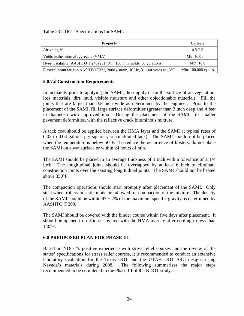
Table 23 UDOT Specifications for SAMI.
Property Criteria
Air voids, % 0.5-2.5
Voids in the mineral aggregate (VMA) Min 16.0 min
Hveem stability (AASHTO T 246) at 140°F, 100 mm molds, 50 gyrations Min. 18.0
Flexural beam fatigue-AASHTO T321, 2000 µstrain, 10 Hz, 3±1 air voids at 15°C Min. 100,000 cycles 5.0.7.d Construction Requirements Immediately prior to applying the SAMI, thoroughly clean the surface of all vegetation, loss materials, dirt, mud, visible moisture and other objectionable materials. Fill the joints that are larger than 0.5 inch wide as determined by the engineer. Prior to the placement of the SAMI, fill large surface deformities (greater than 3 inch deep and 4 feet in diameter) with approved mix. During the placement of the SAMI, fill smaller pavement deformities, with the reflective crack bituminous mixture. A tack coat should be applied between the HMA layer and the SAMI at typical rates of 0.02 to 0.04 gallons per square yard (undiluted tack). The SAMI should not be placed when the temperature is below 50°F. To reduce the occurrence of blisters, do not place the SAMI on a wet surface or within 24 hours of rain. The SAMI should be placed in an average thickness of 1 inch with a tolerance of ± 1/4 inch. The longitudinal joints should be overlapped by at least 6 inch to eliminate construction joints over the existing longitudinal joints. The SAMI should not be heated above 350°F. The compaction operations should start promptly after placement of the SAMI. Only steel wheel rollers in static mode are allowed for compaction of the mixture. The density of the SAMI should be within 97 ± 2% of the maximum specific gravity as determined by AASHTO T 209. The SAMI should be covered with the binder course within five days after placement. It should be opened to traffic or covered with the HMA overlay after cooling to less than 140°F. 6.0 PRPOPOSED PLAN FOR PHASE III Based on NDOT’s positive experience with stress relief courses and the review of the states’ specifications for stress relief courses, it is recommended to conduct an extensive laboratory evaluation for the Texas DOT and the UTAH DOT SRC designs using Nevada’s materials during 2008. The following summarizes the major steps recommended to be completed in the Phase III of the NDOT study:

25
• Select two aggregate sources with different mineralogy and absorption: one in northern Nevada and one in southern Nevada.
• Identify three categories of binders to be used with each of the aggregate sources. All binders must meet the PG64-28 grade for the northern part and the PG76-22 grade for the southern part.
o Polymer modified asphalt binder o Tire rubber terminal blend asphalt binder o Crumb rubber asphalt binder
• For each combination of aggregate source and asphalt binder conduct a mix design according to the TxDOT and UDOT stress relief courses.
• Evaluate the mechanical properties of the SRC mixes in the laboratory in terms of their dynamic modulus, fatigue resistance, rutting resistance using the RLT, thermal cracking resistance using the TSRST, reflective cracking resistance using the TTI Upgraded Overlay tester, and moisture sensitivity.
• Conduct a Type 2C NDOT Hveem Mix design for each of the aggregate sources and the polymer modified asphalt binder.
• Evaluate the mechanical properties of the NDOT T2C mixes in the laboratory in terms of their dynamic modulus, fatigue resistance, rutting resistance using the RLT, thermal cracking resistance using the TSRST, reflective cracking resistance using the TTI Upgraded Overlay tester, and moisture sensitivity.
• Optimize the gradation of the NDOT T2C HMA mixes. Based on the results of the laboratory evaluation, recommendations will be made for constructing field test sections with SRC mixes in 2009. The overlay thickness will be designed using the Rubber Pavements Association Overlay Design Model. Field mixtures from the SRC and overlay mixes will be collected during construction from behind the paver and evaluated for asphalt binder content and gradation. Additionally, the field mixtures will be evaluated in terms of their dynamic modulus, fatigue resistance, rutting resistance using the RLT, thermal cracking resistance using the TSRST, reflective cracking resistance using the TTI Upgraded Overlay tester, and moisture sensitivity. The performance of the field test sections will be monitored and field cores will be sampled for evaluation in the TTI Overlay Tester. Based on the laboratory evaluation and the field performance the specifications for reflective cracking resistance will be adjusted and the most effective technique will be selected.

26
7.0 REFERENCES 1. Elseifi, M., and Al-Qadi, I. (2003). “A Simplified Overlay Design Model Against
Reflective Cracking Utilizing Service Life Prediction,” Paper No. 03-3285 presented at the TRB 82nd Annual Meeting, Washington, D.C.
2. Sousa, J., Pais, J., Saim, R., Way, G., and Stubstad, R. (2001). “Development of a Mechanistic Overlay Design Method Based on Reflective Cracking Concepts,” Final Report for Rubber Pavements Association, Consulpav International.
3. Guide for Mechanistic-Empirical Design of New and Rehabilitated Pavement Structures (2004). Final Report, Part 3 Design Analysis, Ch 6, National Cooperative Highway Research Program, Transportation Research Board, National Research Council.
4. Grzybowska, W., Wojtowicz, J., and Fonferko, L. C. (1993). “Application of Geo-Synthetics to Overlays in Cracow Region of Poland,” Reflective Cracking in Pavements, State of the Art and Design Recommendations, Proceedings of the Second International RILEM Conference, Liege, Belgium, pp. 290-298.
5. Livneh, M., Ishai, I., and Kief, O. (1993). “Bituminous Pre-Coated Geotextile Felts for Retarding Reflection Cracks,” Reflective Cracking in Pavements, State of the Art and Design Recommendations, Proceedings of the Second International RILEM Conference, Liege, Belgium, pp. 343-350.
6. Di Benedetto, H, Neji, J, Antoine, J. P, and Pasquier, M. (1993). “Apparatus for Laboratory Study of Cracking Resistance,” Reflective Cracking in Pavements, State of the Art and Design Recommendations, Proceedings of the Second International RILEM Conference, Liege, Belgium, pp. 179-186.
7. Tschegg, E. K, Stanzl- Tschegg, S. E., and Litzka, J. (1993). “New Testing Method to Characterize Mode 1 Fracturing of Asphalt Aggregate Mixtures,” Reflective Cracking in Pavements, State of the Art and Design Recommendations, Proceedings of the Second International RILEM Conference, Liege, Belgium, pp. 263-270.
8. Dumas, Ph., and Vecoven, J. (1993). “Processes Reducing Reflective Cracking; Synthesis of Laboratory Tests,” Reflective Cracking in Pavements, State of the Art and Design Recommendations, Proceedings of the Second International RILEM Conference, Liege, Belgium, pp. 246-253.
9. Gibney, A., Lohan, G., and Moore, V. (2002). “Laboratory Study of Resistance of Bituminous Overlays to Reflective Cracking,” In Transportation Research Record 1809, TRB, National Research Council pp. 184-190.
10. Dempsey, B. J. (2002). “Development and Performance of Interlayer Stress Absorbing Composite (ISAC) in AC Overlays”. In Transportation Research Record 1809, TRB, National Research Council pp. 175-183.
11. Montestruque, G., Rodrigues, R., Nods, M., and Elsing, A. (2004). “Stop of Reflection Crack Propagation with the Use of Pet Geogrid as Asphalt Overlay Reinforcement,” Cracking in Pavements, Mitigation, Risk Assessment and Prevention, Proceedings of the Fifth International RILEM Conference, Lomoges, France, pp. 231-238.

27
12. Sobhan, T., Crooks, T., Tandon, T., and Mattingly, S. (2004). “Laboratory Simulation of the Growth and Propagation of Reflection Cracks in Geogrid Reinforced Asphalt Overlays,” Cracking in Pavements, Mitigation, Risk Assessment and Prevention, Proceedings of the Fifth International RILEM Conference, Lomoges, France, pp. 589-596.
13. Gallego, J., and Prieto, J. N. (2006). “Development of New Laboratory Equipment for the Study of Reflective Cracking in Asphalt Overlays,” In Asphalt Overlays and Infrastructure Distress. CD-ROM. Transportation Research Board of the National Academies, Washington, D.C.
14. Tamagny, P., Wendling, L., and Piau, J. M. (2004). “A New Explanation of Pavement Cracking from Top to Bottom: The Visco-elasticity of Asphalt Materials,” Cracking in Pavements, Mitigation, Risk Assessment and Prevention, Proceedings of the Fifth International RILEM Conference, Lomoges, France, pp. 425-432.
15. Zhou, F., and Scullion, T. (2005). “Overlay Tester: A Rapid Performance Related Crack Resistance Test,” Texas Transportation Institute, the Texas A&M University System, Report FHWA/TX-05/0-4667-2, Austin, Texas.
16. Standard Specifications for Highway Construction (2000). Arizona Department of Transportation, ADOT, Sections 404, 410 and 1009. http://www.dot.state.az.us/Highways/cns/CNS_Stored_specs.asp.
17. Asphalt Rubber Usage Guide Division of Engineering Services (2003). California Department of Transportation, Caltrans, http://www.dot.ca.gov/hq/esc/Translab/pubs/Caltrans_Asphalt_Rubber_Usage_Guide.pdf.
18. Standard Specifications for Highway Construction (2005). Florida Department of Transportation, FDOT, Sections 336, 341 and 916, http://www.dot.state.fl.us/Specificationsoffice/2007BK/TOC.htm.
19. Standard Specifications for Highway Construction (2006). Iowa Department of Transportation, IDOT, Sections 2303, 2310 and 4127. http://www.erl.dot.state.ia.us/OCT_2006/GS/frames.htm.
20. Standard Specifications for Highway Construction (1995). Massachusetts Department of Transportation (MDOT), Section 466, http://www.mhd.state.ma.us/default.asp?pgid=content/publicationmanuals&sid=about
21. Standard Specifications for Highway Construction (2004). Texas Department of Transportation TxDOT, CSJ 0353-04-090, Section 3141.
22. Standard Specifications for Highway Construction (2002). Utah Department of Transportation, UDOT, Section 02744S, http://www.udot.utah.gov/download.php/tid=520/UDOT2002SpecsBasic.pdf.
Nevada Department of Transportation
Rudy Malfabon, P.E. Director
Ken Chambers, Research Division Chief
(775) 888-7220
1263 South Stewart Street
Carson City, Nevada 89712