reflections on the wright experience…
TRANSCRIPT

Reflections on the Wright Experience…
Kevin Kochersberger, Ph.D.Rochester Institute of
TechnologyMechanical Engineering
Rochester, NY 14623
From a dream to first powered flight

Aeronautical Experimentalists
Alphonse Penaud (1850 - 1880)Built the first longitudinally and laterally stable glider models
Samuel Langley (1834 - 1906)Whirling arm lift and drag measurements of flat platesSuccessful flights of steam powered models (the Aerodromes)Unsuccessful attempt at manned, powered flight on December 8, 1903 of a full-scale Aerodrome
The earliest flights
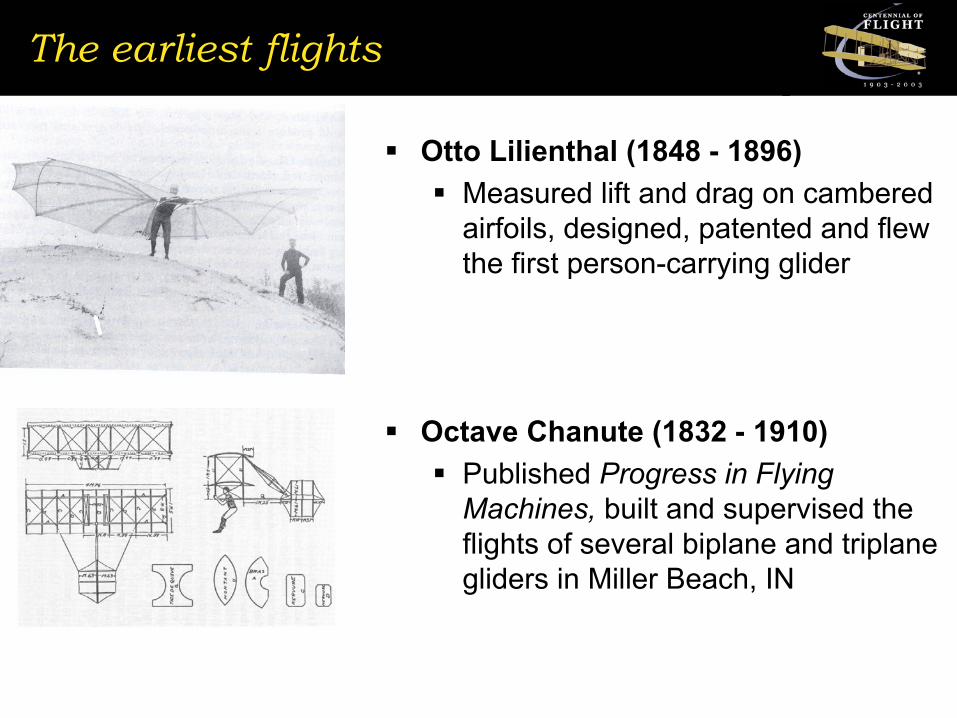
Otto Lilienthal (1848 - 1896)Measured lift and drag on cambered airfoils, designed, patented and flew the first person-carrying glider
Octave Chanute (1832 - 1910)Published Progress in Flying Machines, built and supervised the flights of several biplane and triplane gliders in Miller Beach, IN

And then, the Wright brothers...
Wilbur (1867 - 1912) Orville (1871 - 1948)
Early Experiments
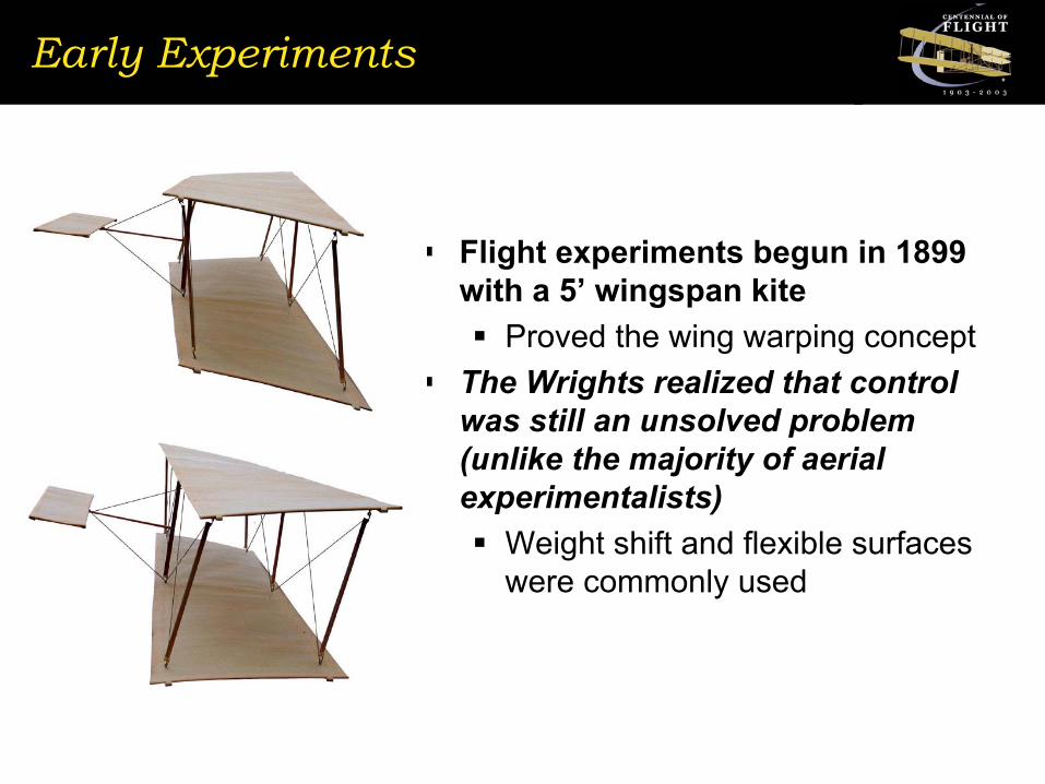
Flight experiments begun in 1899 with a 5’ wingspan kite
Proved the wing warping conceptThe Wrights realized that control was still an unsolved problem (unlike the majority of aerial experimentalists)
Weight shift and flexible surfaces were commonly used

The 1900 - 1901 Gliding Experiments
First full-sized glider built in 1900 – Flew at Kitty Hawk briefly“…hours of practice we had hoped to obtain finally dwindled down to about two minutes…”
A larger glider was constructed in 1901 to correct the deficiency in lift found in the 1900 glider
Low aspect ratio, high pitching-moment and adverse yaw = difficult to fly!

Some success, but not enough...
Pitch instability corrected by “trussing down” the wingsLongest flight: 389 ft.Actual lift was much less than predicted
View lookingForward
...Became a turn to the left!
And a turn to the right...
???
Engineering a solution
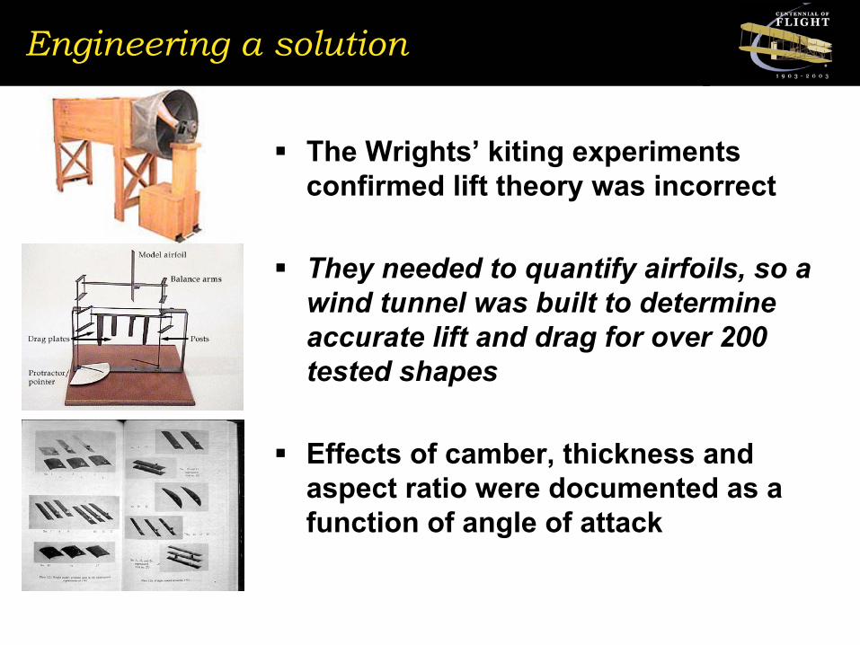
The Wrights’ kiting experiments confirmed lift theory was incorrect
They needed to quantify airfoils, so a wind tunnel was built to determine accurate lift and drag for over 200 tested shapes
Effects of camber, thickness and aspect ratio were documented as a function of angle of attack


1902 Glider
1902 glider: A modern airplane
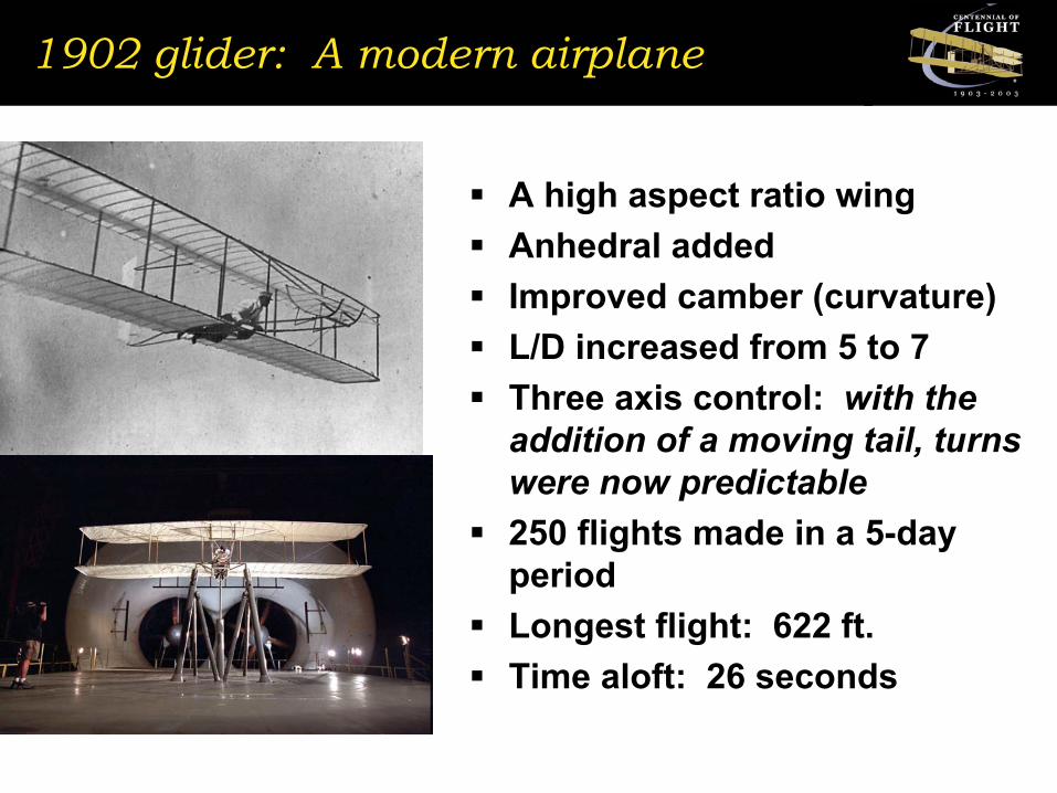
A high aspect ratio wingAnhedral addedImproved camber (curvature)L/D increased from 5 to 7Three axis control: with the addition of a moving tail, turns were now predictable250 flights made in a 5-day periodLongest flight: 622 ft.Time aloft: 26 seconds
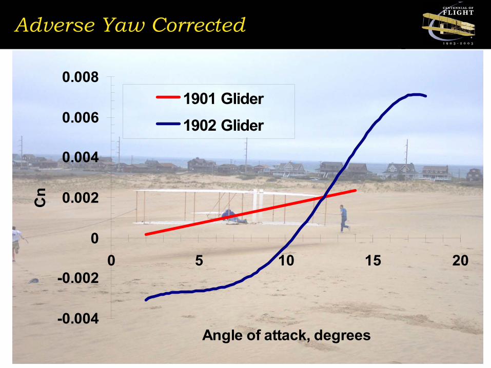
Adverse Yaw Corrected
-0.004
-0.002
0
0.002
0.004
0.006
0.008
0 5 10 15 20
Angle of attack, degrees
Cn
1901 Glider1902 Glider

And more warp power
0
0.005
0.01
0.015
0.02
0.025
0.03
0 5 10 15 20
Angle, degrees
Rol
l Coe
ff, C
l
1901 Roll Control Power
1902 Roll Control Power

But still have a variable stability aircraft
-0.05
-0.03
-0.01
0.01
0.03
0.05
0.07
-5 0 5 10 15 20 25
Angle of Attack, degrees
Cm
1901 Glider1902 Glider
Unstable!
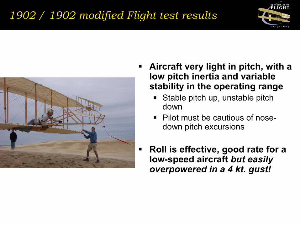
1902 / 1902 modified Flight test results
Aircraft very light in pitch, with a low pitch inertia and variable stability in the operating range
Stable pitch up, unstable pitch downPilot must be cautious of nose-down pitch excursions
Roll is effective, good rate for a low-speed aircraft but easily overpowered in a 4 kt. gust!

What’s left?
A reliable engineA propeller designProvision for launching on level groundThe integration of the new systems into the airframeWind!

The 1903 Engine
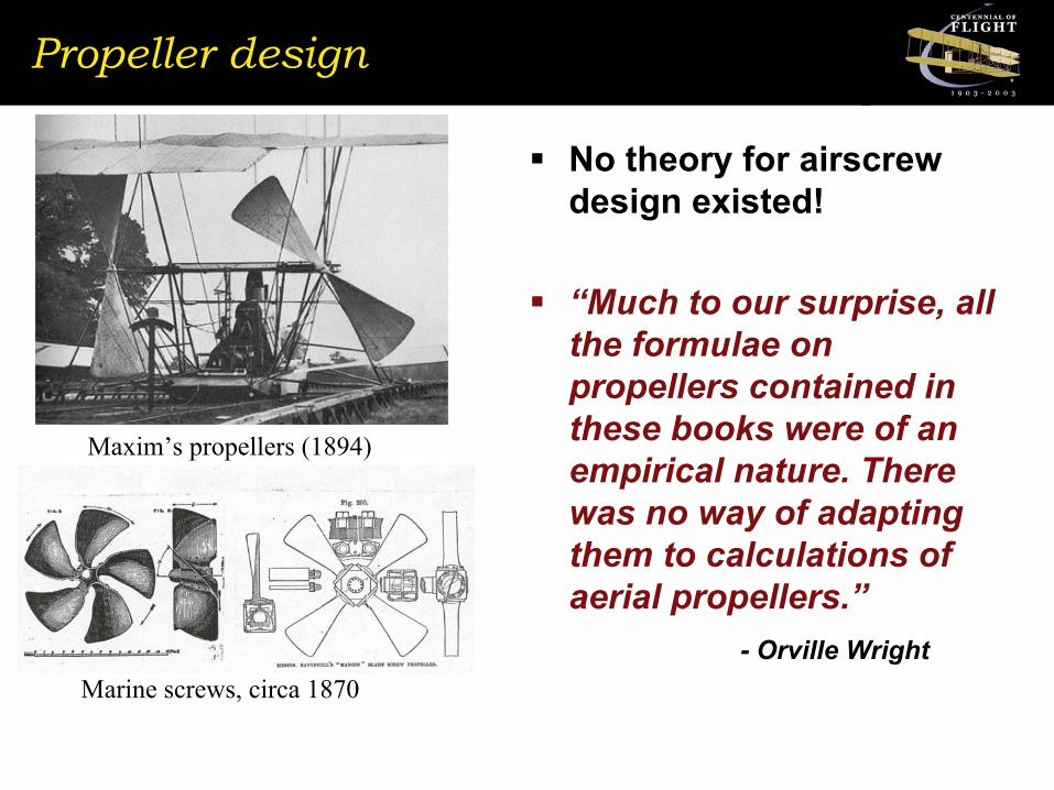
Propeller design
No theory for airscrew design existed!
“Much to our surprise, all the formulae on propellers contained in these books were of an empirical nature. There was no way of adapting them to calculations of aerial propellers.”
- Orville Wright
Maxim’s propellers (1894)
Marine screws, circa 1870
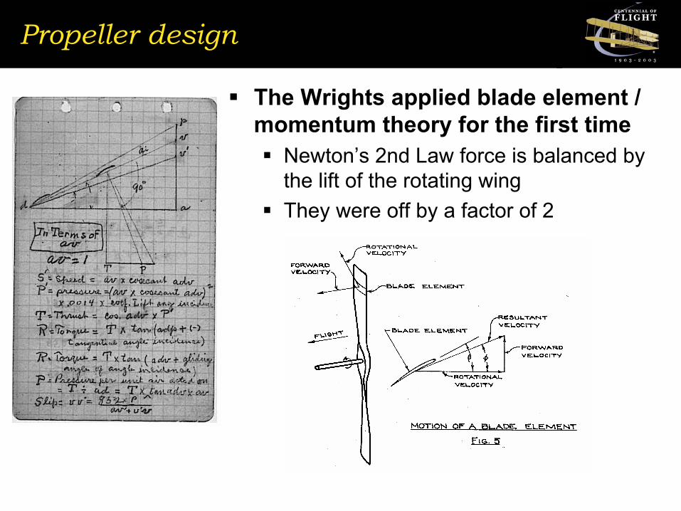
Propeller design
The Wrights applied blade element / momentum theory for the first time
Newton’s 2nd Law force is balanced by the lift of the rotating wingThey were off by a factor of 2
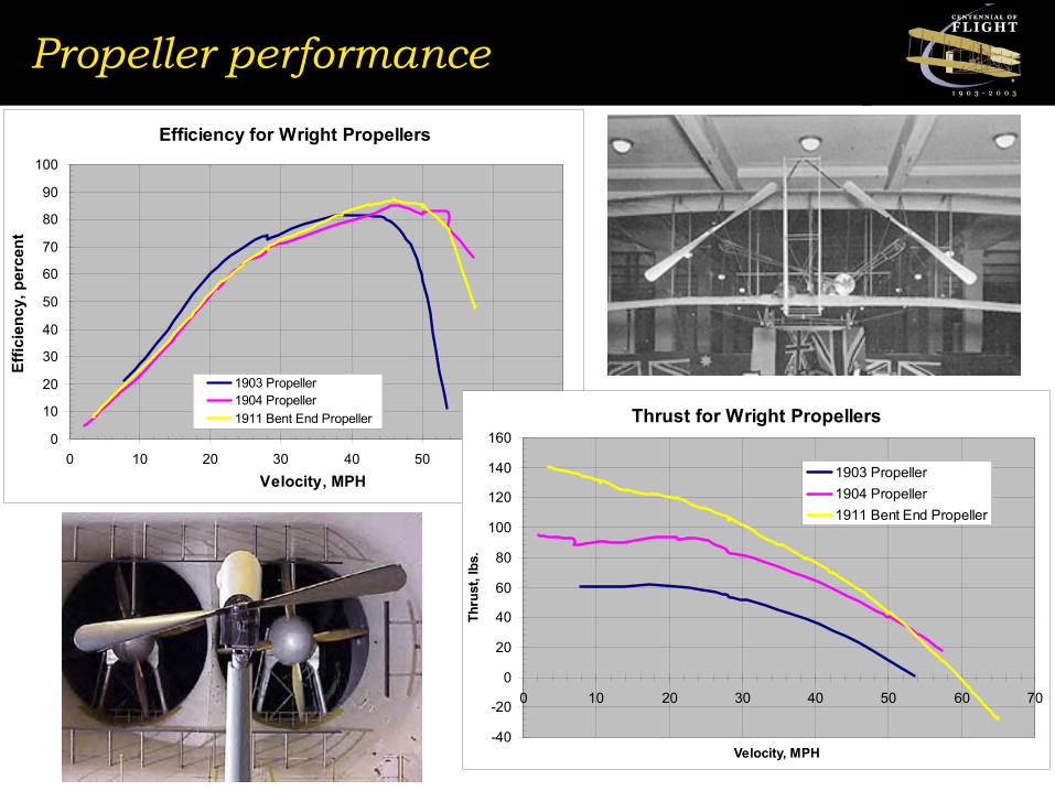
Propeller performanceEfficiency for Wright Propellers
0
10
20
30
40
50
60
70
80
90
100
0 10 20 30 40 50 60 70Velocity, MPH
Effic
ienc
y, p
erce
nt
1903 Propeller1904 Propeller1911 Bent End Propeller Thrust for Wright Propellers
-40
-20
0
20
40
60
80
100
120
140
160
0 10 20 30 40 50 60 70
Velocity, MPH
Thru
st, l
bs.
1903 Propeller1904 Propeller1911 Bent End Propeller

The Wright Experience Reproduction

Wing structure

Fabric
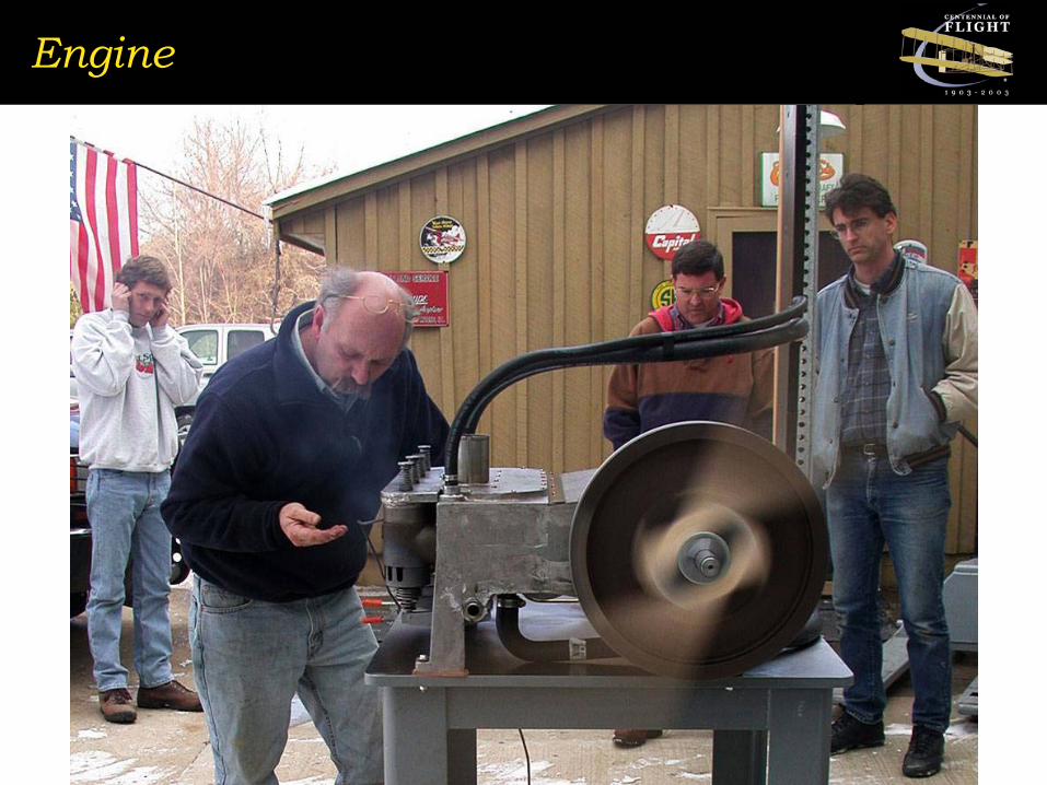
Engine

Propellers
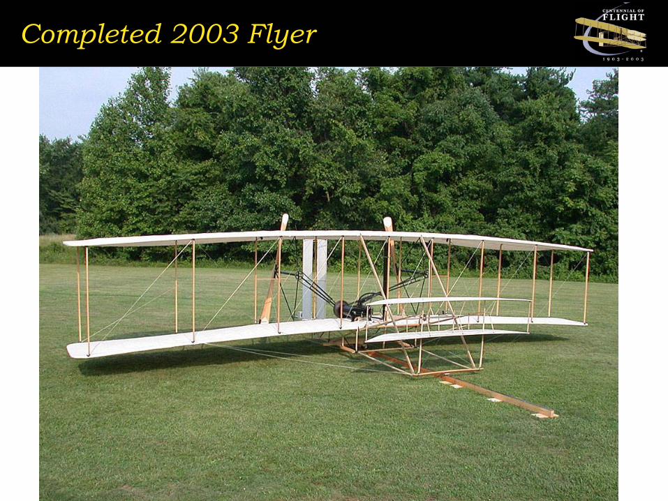
Completed 2003 Flyer
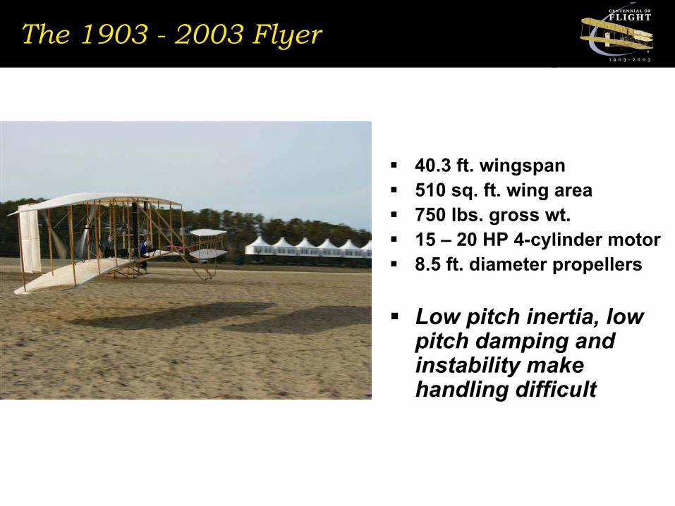
The 1903 - 2003 Flyer
40.3 ft. wingspan510 sq. ft. wing area750 lbs. gross wt.15 – 20 HP 4-cylinder motor8.5 ft. diameter propellers
Low pitch inertia, low pitch damping and instability make handling difficult
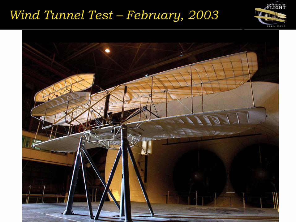
Wind Tunnel Test – February, 2003
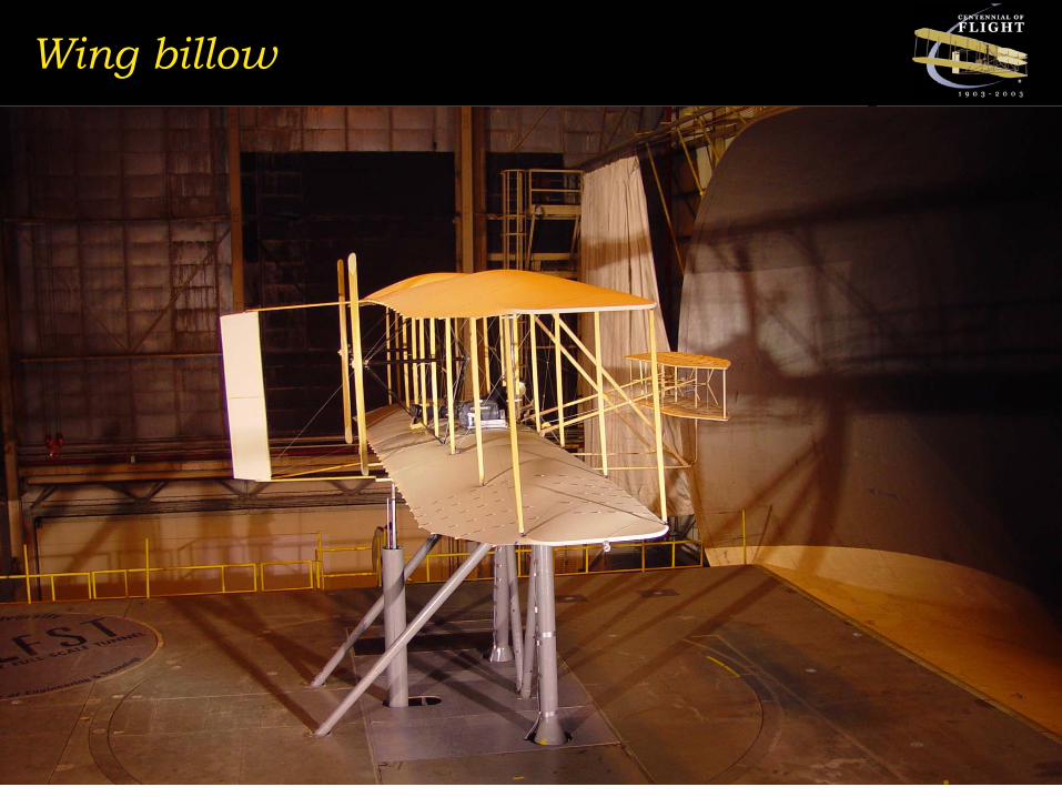
Wing billow
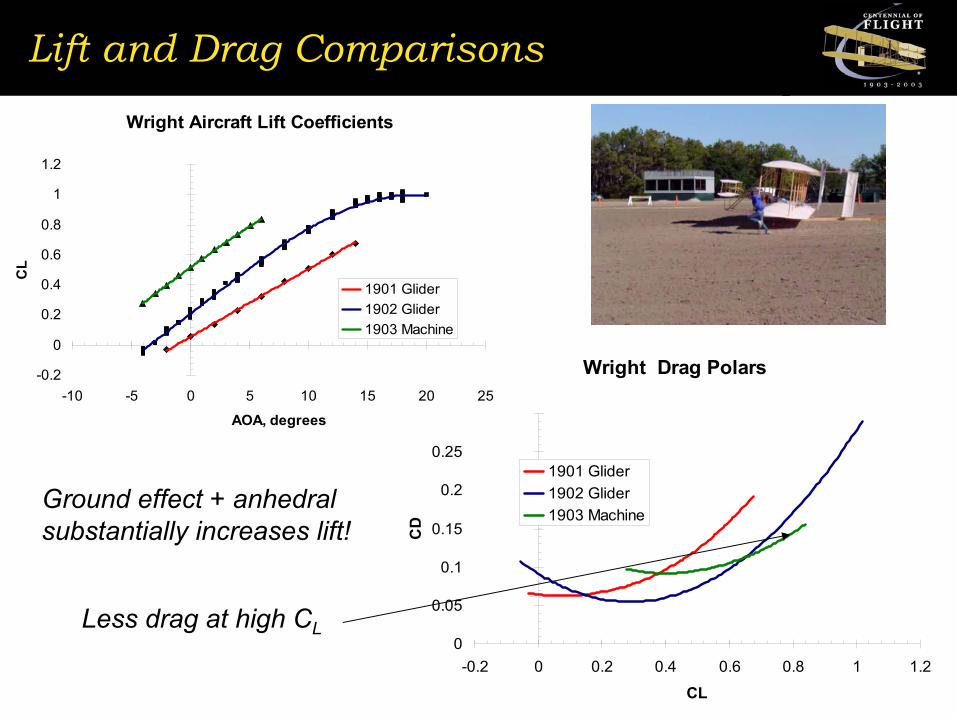
Lift and Drag Comparisons
Wright Drag Polars
0
0.05
0.1
0.15
0.2
0.25
0.3
-0.2 0 0.2 0.4 0.6 0.8 1 1.2
CL
CD
1901 Glider1902 Glider1903 Machine
Ground effect + anhedralsubstantially increases lift!
Wright Aircraft Lift Coefficients
-0.2
0
0.2
0.4
0.6
0.8
1
1.2
-10 -5 0 5 10 15 20 25
AOA, degrees
CL
1901 Glider1902 Glider1903 Machine
Less drag at high CL
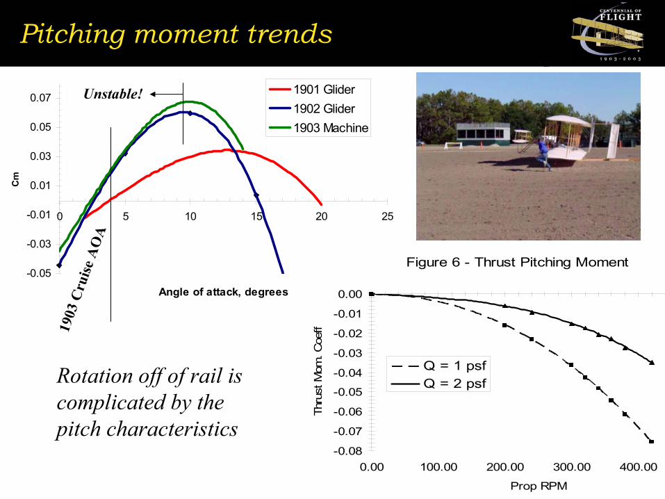
Pitching moment trends
-0.05
-0.03
-0.01
0.01
0.03
0.05
0.07
0 5 10 15 20 25
Angle of attack, degrees
Cm
1901 Glider1902 Glider1903 Machine
Figure 6 - Thrust Pitching Moment
-0.08
-0.07
-0.06
-0.05
-0.04
-0.03
-0.02
-0.01
0.00
0.00 100.00 200.00 300.00 400.00
Prop RPM
Thru
st M
om. C
oeff
Q = 1 psfQ = 2 psf
Unstable!
1903
Cru
ise A
OA
Rotation off of rail is complicated by the pitch characteristics

1903 Machine Pitching Moment
Figure 5 - Canard Control Power
-0.25-0.20-0.15-0.10-0.050.000.050.10
-5.00 0.00 5.00 10.00 15.00
Angle of attack, deg.
Cm Canard +20 deg.
Canard +10 deg.Canard +5 deg.Canard 0 deg.Canard -5 deg.Canard -13 deg.
Q = 2,28 MPH
-17% static margin at cruise AOA!!!

16 HP motor - power available
Power available / power reqd.
6
7
8
9
10
11
12
13
14
15
16
20 25 30 35 40Velocity, MPH
Pow
er, H
P
Engine power at prop750 lbs. gross wt.760 lbs. gross wt.
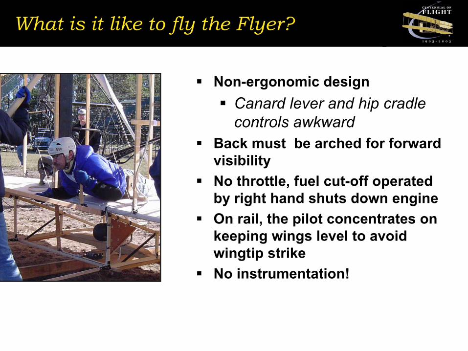
What is it like to fly the Flyer?
Non-ergonomic designCanard lever and hip cradle controls awkward
Back must be arched for forward visibilityNo throttle, fuel cut-off operated by right hand shuts down engineOn rail, the pilot concentrates on keeping wings level to avoid wingtip strikeNo instrumentation!
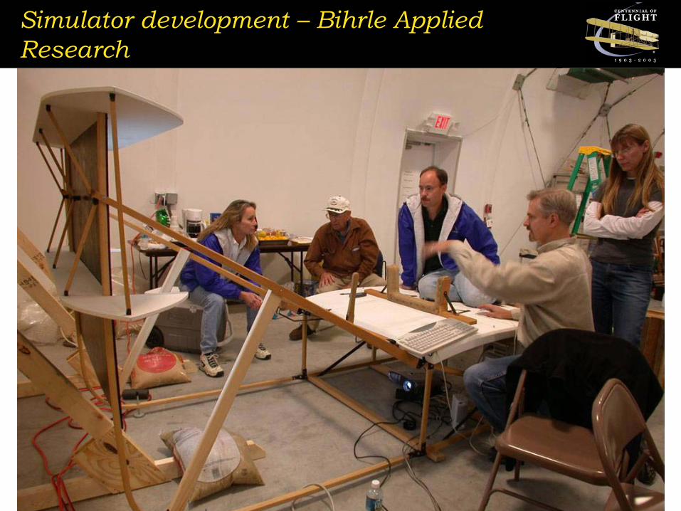
Simulator development – Bihrle Applied Research

Figure 13 - Flight #1 Data
-40
-30
-20
-10
0
10
20
30
40
419 424 429 434
Time, sec.
Ang
le, d
eg. a
nd S
peed
,M
PH
310
320
330
340
350
360
370
380
390
Pro
p R
PM
Canard defl., deg.Speed, MPHProp RPM
Bihrle Simulator matched flight data well
Figure 12 - Simulated Longitudinal Flight
-10.00-5.000.005.00
10.0015.0020.0025.0030.0035.00
0.00 5.00 10.00 15.00
Time, sec.
Angl
e, d
eg. a
nd V
el.
MPH
0.00
1.00
2.00
3.00
4.00
5.00
6.00
Altit
ude,
ft.
Angle of attack, deg.Canard defl., deg.Vel., MPHAltitude, ft. Aircraft shows pilot-in-the-loop
phugoid frequency of 0.5Hz
Canard deflection frequency of 2 Hz!
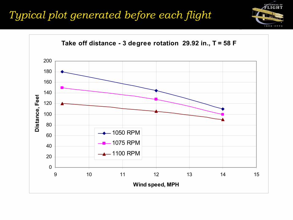
Typical plot generated before each flight
Take off distance - 3 degree rotation 29.92 in., T = 58 F
0
20
40
60
80
100
120
140
160
180
200
9 10 11 12 13 14 15
Wind speed, MPH
Dis
tanc
e, F
eet
1050 RPM
1075 RPM
1100 RPM
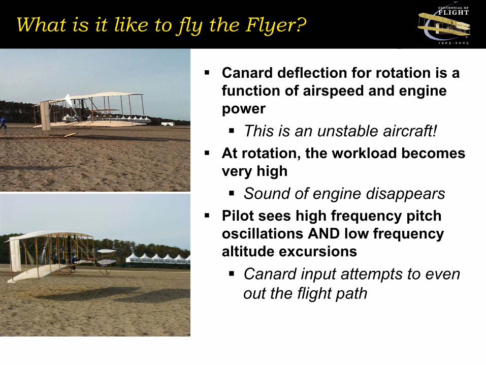
What is it like to fly the Flyer?
Canard deflection for rotation is a function of airspeed and engine power
This is an unstable aircraft!At rotation, the workload becomes very high
Sound of engine disappearsPilot sees high frequency pitch oscillations AND low frequency altitude excursions
Canard input attempts to even out the flight path

Vigyan Flight Data Recorder
Measurements List
1. Pitot Pressure2. Static Pressure3. α4. β5. Pitch Control Deflection6. Wing Warp Deflection
7. nxCG10. nxnose
8. nyCG11. nynose
9. nzCG12. nznose
13. RPM14. Torque
1,2,3,4: Pitot, Static, α, β (Ceneter Line)
Transmit Antenna
13: RPM on Left Sprocket
14: Torque Strain Gage on Left Prop. Shaft
6: Wing Warp Deflection(Left Side)7, 8, 9:
CG Tri AxialAccelerometer
(Right Side)
10, 11, 12:Nose Tri AxialAccelerometer
(Right Side)
5: Pitch Control Deflection(Left Side)
Receive AntennaTorque Measurement
●
Data Recorder(Left Side)
x x
Data Acquistion System Layout
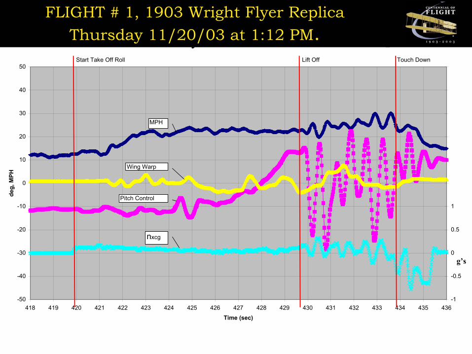
FLIGHT # 1, 1903 Wright Flyer ReplicaThursday 11/20/03 at 1:12 PM
-50
-40
-30
-20
-10
0
10
20
30
40
50
418 419 420 421 422 423 424 425 426 427 428 429 430 431 432 433 434 435 436
Time (sec)
deg,
MPH
-1
-0.5
0
0.5
1
1.5
2
2.5
3
3.5
4
MPH
Wing Warp
Pitch Control
nxcg
Start Take Off Roll Lift Off Touch Down
g’s
FLIGHT # 1, 1903 Wright Flyer ReplicaThursday 11/20/03 at 1:12 PM.
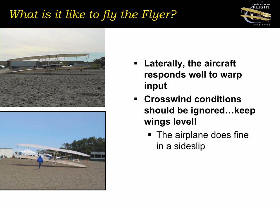
What is it like to fly the Flyer?
Laterally, the aircraft responds well to warp inputCrosswind conditions should be ignored…keep wings level!
The airplane does fine in a sideslip
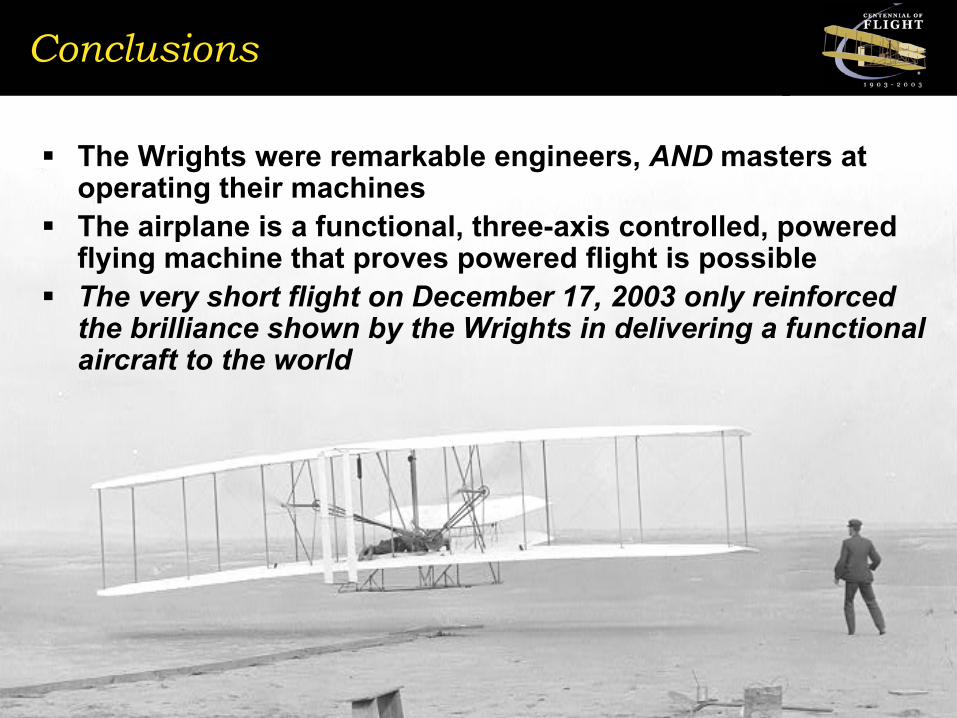
Conclusions
The Wrights were remarkable engineers, AND masters at operating their machinesThe airplane is a functional, three-axis controlled, powered flying machine that proves powered flight is possibleThe very short flight on December 17, 2003 only reinforced the brilliance shown by the Wrights in delivering a functional aircraft to the world