reflected uv imaging for forensics v2 - company 7 · pdf filereflected ultraviolet imaging for...
TRANSCRIPT

Reflected Ultraviolet Imaging for Forensics Applications
Dr. Austin Richards
Adjunct Professor, Brooks Institute of Photography
Partner, Oculus Photonics, Santa Barbara, CA
Senior Research Scientist, FLIR Commercial Systems
+1-805-284-5757
Updated 3/28/10
Introduction: Reflected-UV imaging is a method of photographing objects using reflected UV light, as opposed to the imaging of UV fluorescence. Reflected-UV imaging is quite often confused with UV fluorescence imaging in the literature and in conversation, since people tend to shorten both these terms to “UV imaging”. It is important to distinguish the two methods, since they will give very different results when applied to the same scene.
Reflected-UV imaging: UV illumination reflects off a scene and is recorded by a UV-
sensitive camera
UV Fluorescence imaging: UV illumination stimulates fluorescence at a longer
wavelength than the UV excitation source. The resulting fluorescence is typically in
the visible band. A color camera with a UV-blocking filter is used to record the
fluorescence image.
Reflected-UV imaging has a checkered history in forensics imaging. It is often difficult to get good results with a film camera and many forensic photographers have tried it, only to give up in frustration. A widespread myth was that one HAD to use a quartz lens to record UV images, so few people attempted it, even though it turns out that many conventional lenses designed for color imaging work quite well in the near-UV band. What is quite true is that a special lens made of quartz (more properly called fused silica) or calcium fluorite is necessary to record images in the shortwave UV band, since glass does not transmit light well below about 310nm. But many authors writing about UV techniques did not make the distinction between near-UV and shortwave-UV and the myth of the quartz lens spread. For the purposes of this discussion, the near-UV band is defined as 300nm to 400nm in wavelength. The shortwave UV band is defined as 200-300nm. Human vision rolls off rapidly at wavelengths below 400nm, due to the protein absorption of the eye’s crystalline lens. Light much below 400nm in wavelength is essentially invisible to the eye, though it may generate visible fluorescence within the eye. There are forensic applications for both near and shortwave UV imaging.
Film cameras:
The typical film photography method starts with a panchromatic film like Kodak T-Max 400 which has good response to UV. The photographer then uses a special UV-pass filter that blocks visible light from reaching the film, but this black glass filter also prevents the photographer from composing the shot or focusing it properly while it is installed. Note that this filter is not the same as a skylight filter which is designed to prevent any ambient UV light from reaching the film. The camera is generally mounted on a tripod, the shot is composed and a focus is established by eye. For a typical glass lens, this focus will shift when the UV image is recorded, so standard practice is to shoot at a high f/number for greater depth of field. Special lenses designed for UV imaging are color corrected for both visible light and UV, which eliminates the focus problem. The black glass filter is then installed and the photographer shoots the scene, and brackets the shots in the hopes of getting a properly exposed image. A UV light source must be used, since tungsten lights are not strong emitters in the UV band, and the typical camera’s light meter is useless, as it is not calibrated in the UV band. The filter factor of the black glass filter is often 6 stops, as I found with my Schott UG-1 glass filter. Add that filter factor to the high f/number and you get long exposures, often over 1 second. The film method was never very popular and was only applied to certain niche applications.
Digital cameras:
In the digital age, forensic photographers tried to use their new digital cameras to record near-UV images. If they used their old black glass filter that worked with film (typically a Wraten 18A filter), they often got a surprise. The resulting images were almost always near-infrared, NOT near-UV, especially if tungsten lighting was used as the illumination source. The near-infrared band is generally defined as 750nm to 1100nm. 750nm is the wavelength at which human vision is starting to roll off rapidly. 1100nm is the wavelength at which silicon detectors become insensitive – the light literally travels right through. The black glass filters all have a large red leak, an artifact of the filtration method of using special metal ions mixed into the glass. Their digital cameras were often equipped with a barrier filter that blocks UV from reaching the sensor, biasing the image even more strongly to the red leak. The photographers thus were left with an image that did not look like what UV film photography records and concluded that their digital camera would not work for this application. They were right, although there are some digital SLRs out there that happen to have reasonable UV response. But few photographers knew which ones had UV sensitivity or even cared. The use of reflected-UV imaging was heading for oblivion in the crime lab as the use of film declined. In 2006, the introduction of the Fuji S-3 UVIR camera into the forensics market changed the situation. This DSLR camera was marketed as having both near-UV and near-IR response, though it actually has roughly five times more response in the near-IR than in the near-UV band, according to my measurements. As far as I know, the difference between the Fuji UVIR and other Fuji DSLRs is that a blocking filter that removed both near-UV and near-IR light from the image was not installed in the UVIR cameras. The camera does not have a special sensor; it is the same sensor used in their color cameras.

This means that it is unfortunately equipped with Bayer color filters, which have the effect of reducing the near-UV signal reaching the sensor and also generate confusion over which color channel to use. It is am important point here – a near-UV image should always be monochrome. One color channel should be selected out of the RGB raw image. Fuji did not publish a spectral response curve for the various color channels of the camera; in fact I am not sure they even measured the response, since no one I talked to at Fuji could tell me if these curves even exist. The cameras were often sold as part of a forensics imaging kit, which included a filter that is just like the black glass filters of old – it has a red leak. But the Fuji sensor is much more responsive to red and near-IR light than to near-UV. Thus, photographers using the UV pass filter that came with the kit concluded that the camera was not very useful for reflected-UV imaging, which is not correct. The camera actually will take very nice reflected-UV images but only if it is used with the proper filters, lenses and lighting and the correct color channel is selected out of the raw images!
Reflected-UV imaging applications: It is well known that UV light has properties that make it a very powerful investigative tool for forensics, particularly because it makes many substances fluoresce. Less well known is the power of reflected-UV imaging to reveal hidden evidence. It does this for several reasons: Absorption: UV light is highly absorbed by many commonly encountered organic materials, yet is reflected by many inorganic materials like stone and metal. If these organic materials are on a surface with higher UV reflectance, the substances will often stand out more strongly than visible-light or near-IR images. The reverse is true as well – traces of inorganic materials like salt stand out as bright on a dark organic surface like a wooden table. Lack of penetration: UV light does not penetrate even very thin layers of materials, making surface topology more apparent, since normally translucent surfaces appear opaque. The high energy of UV photons makes them interact strongly with the electrons in atoms and molecules. Many materials look very dark when imaged with UV light. Highly scattered UV waves: UV lightwaves have a short wavelength, which means that they are scattered much more readily by small surface imperfections on a smooth surface than either visible or near-IR light. Scratches and dust are much more apparent, which is why the optics industry uses UV imaging to inspect lens surfaces, for example. Some of the texture imaging can be accomplished by raking-illuminated visible-light photography, though UV has advantages over raking light.
Reflected-UV imaging applications:
These three properties of the interaction between materials and UV light make reflected-UV imaging very useful for certain applications in forensics imaging. These are the primary applications that are well documented in the literature:
• The imaging of bitemarks and other pattern injuries on skin
• The imaging of shoeprints on surfaces where visible-light contrast is low
• The imaging of latent fingerprints The latter application requires an imaging system that works in the shortwave UV band, unless the fingerprints are made while the fingers were coated with a substance that absorbs near-UV light, like sunscreen. These applications represent the historical use of reflected-UV imaging in forensics, but I believe it to be incomplete, and I would add the following applications:
• Imaging traces of certain substances on certain classes of surfaces.
• Imaging changes in surface texture on smooth surfaces caused by physical contact Most of the time, forensic investigators only imaged what they knew was already there, because of the difficulties inherent in reflected-UV imaging with film. Thus these last two applications have historically received very little attention, due to the fact that the presence of the anomaly may only be apparent in the UV band. Unless the
photographer had a means of scanning the scene with a UV imaging scope or video
camera, he or she might never know to photograph in a certain area of a crime
scene with reflected UV to discover invisible forensic evidence! In some cases, traces of materials and changes in surface texture can be imaged with raking light illumination, or by imaging the surface at a highly oblique angle. This is not always possible due to geometric constraints. In some cases, UV imaging works better than raking-light imaging, especially in situations where the surface anomaly is subtle, as we will see below. UV viewing scopes are available to the forensics market. My company, Oculus Photonics, manufactures near-UV video camera systems. We have designed a system that is highly immune to both visible light and near-IR light. We have plugged the red leak, and our cameras see a highly pure near-UV image, even in direct sunlight. Other UV viewing scopes are on the market, but they are supplied with UV filters with red leaks and little guidance on how to properly image only in the UV band.
Examples of reflected-UV forensic images:
I’ll now take you through a set of examples from each application category.
Bitemarks and pattern injuries:
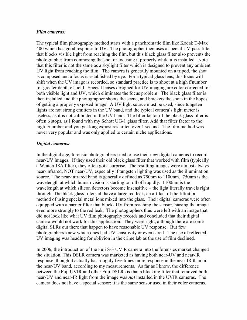
The near-UV band is commonly used for this application. There are two classes of bitemark or pattern injury near-UV images: fresh and several months old. We will consider both classes: Fresh marks: Near-UV light rays do not penetrate into skin very far at all compared to visible light, so they can allow a CSI to record just the surface topology of the skin
without also recording the bruising under the skin that can obscure the dentition patterns when visible light imaging is used. An example is shown in Figure 1 below. Though I do not have photographic data to back up my assertion, I believe that shortwave UV imaging could further enhance fresh bitemarks because of its very minimal penetration into skin. This method would be best used only on corpses, as shortwave UV light is a strong skin irritant.
Figure 1. Visible-light and reflected near-UV images of a fresh bitemark
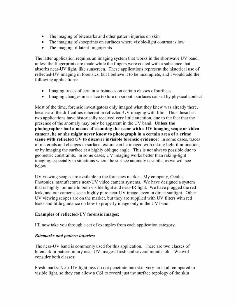
Old marks: After several months, bitemarks or pattern injuries can fade away so that they are barely visible to the eye. However, melanin can concentrate in the injured areas, leading to hyperpigmentation of the skin over several months time, especially in Caucasian skin. It is almost as though the bitemark “develops” in the near-UV band like a Polaroid picture. Observation of this hyperpigmentation can be enhanced by near-UV imaging, since melanin absorbs UV light strongly. Figure 2 shows an excellent example of this.
Figure 2. Five month old bitemark on living victim. Left – black and white film image, right, near-
UV film image. Courtesy of Stephen Warlen.

Near-IR images by accident:
Some of the bitemark photos I have seen in the literature and on the web appear to actually be near-IR images, because the UV filter also leaked near-IR light and no special steps were taken to control the spectral content of the scene lighting. An example of this kind of contaminated image is shown in Figure 3. Note that the skin actually looks much darker in the near-UV band than it does in this picture:
Figure 3. Bitemark images from CSI Forensics Forum Issue 32, Oct-Dec 2008,
Kansas City MO Police Crime Laboratory. Courtesy of Stephen Warlen.
A true near-UV image will show Caucasian skin as darker than what the eye or a near-IR camera sees, and the bruising that tends to obscure the surface impressions will be much less apparent, since UV penetration is so minimal, as shown in Figure 1. The surface impressions are especially deep and well-defined on the right side of the UV image of the bitemark. The contamination in Figure 3 occurred because the PECA 900 filter that used as the UV pass filter has a large red leak, as shown in Figure 4. The PECA company set out to make a filter that is just like the Wratten 18A which Kodak discontinued some time ago, and which are now hard to find. They succeeded, and the PECA 900 works fine with panchromatic film which is quite insensitive to red and near-infrared light. But this filter is very problematic when used with the Fuji UVIR, which is a lot more responsive to red and near-infrared light than it is to UV light. Its transmission curve is very similar to many other special photographic UV pass filters made of “black glass” that are on the market. An easy way to tell if your UV filter has a red leak is to look at a light source that has lots of red and near-IR light and very little UV through the filter. Hold it up to

your eye with your hand cupped around the filter so you only see light that goes through it. When you look through the filter at an incandescent light-bulb, for example, you should see the source in the deepest shades of red. This is possible because your eye will see a little into the near-IR band if there is no visible light present. A standard incandescent lightbulb has a color temperature of 3000K, and therefore emits approximately 30 times as much radiation at 750 nm as it does at 350nm. Even though the red leak filter transmission is perhaps 25% of the UV peak center wavelength, the near-IR signal will dominate. I have tried this trick on many filters and I can always see the red leak, with one important exception which we’ll get to. Incidentally, you can also see a little into the UV band, again only if there is no visible light presented to the eye. Try looking through your black-glass UV pass filter at the blue sky near the horizon with the cupped hand technique. You should see a dim deep purple image of the sky and any landscape features silhouetted by it. Clear blue sky is very rich in scattered blue and near-UV light, and has almost no red or near-IR component to it, especially when looking away from the sun. I have noticed that several companies have discontinued their UV pass filter over the last 20 years, Tiffen for example. It is a vicious circle – people have poor luck with UV photography, so they don’t buy the equipment and the products are taken off the market, making the technique even more difficult due to reduced equipment availability. The biggest problem the reflected-UV imaging field has suffered from is a lack of coherent, factual information. That is the purpose of this paper – to share the knowledge I have gleaned over the years. As a teenager interested in UV photography, I once asked a man that worked in a quite reputable camera store if they made film that was sensitive to UV light. He had no idea, and covered up his ignorance with this throwaway comment: “They could make film covered with dog s**t if they wanted to.” That was 25 years ago and there is still a high level of ignorance in the photographic community when it comes to reflected-UV imaging.

Figure 4. PECA 900 curve from their website: www.IR-UV.com
I have discussed the spectral curve of this model 900 filter with key personnel at PECA and they acknowledge the red leak1. To be fair, this red leak is not a problem if the filter is used in conjunction with both a sufficiently strong near-UV light source and the absence of any ambient light in the 650-800nm red leak band. The fault here lies with Fujifilm, Inc. They made little effort to properly educate customers that bought the full PECA filter kit as part of the Fuji S-3 UVIR forensics package that this 900 filter cannot
be used as is with the Fuji unless the lighting environment has negligible red and near-infrared light. If the room lights are on, there will be red and near-IR contamination of the image, which is what appears to have happened in the bitemark image in Figure 3. This is a serious issue for forensics photographers that bought the forensics package from Fuji. We are trying to spread the word amongst the community. A recent article written by my colleagues at the Miami-Dade Police Dept. and myself for the Journal of Forensic Identification discusses the red leak issue in detail. (Sanfilippo el al., JFI Volume 60, Issue 2, March/April 2010, pages 181-198).
Shoeprint imaging:
Shoeprints made with light colored dirt on a light colored surface can be very difficult to photograph with any degree of contrast using conventional color photography. The near-UV imaging method can sometimes greatly increase contrast in this situation, particularly
1 Gary Garnett, private communication

when the substrate is an organic material like wood or cloth. In that case, the organic substrate records as very dark, because UV is absorbed by it, while the generally inorganic dirt or dust often tends to reflect near-UV, as shown in Figure 5:
Figure 5. Dusty shoeprint made on masonite stool top. Left – color, right – near-UV film image.
Courtesy of Stephen Warlen.
Imaging latent fingerprints:
Fingerprints made when the fingers are coated with a UV-absorbing substance can be recorded very effectively with near-UV imaging. It is much more common for latent fingerprints to be the result of the bodies’ own secretions, either sweaty or sebaceous, in which case near-UV imaging is typically not any more effective that the naked eye. However, shortwave UV imaging can record latent sweaty or sebaceous fingerprints very effectively. It is not practical to attempt to record images in the shortwave UV band with the Fuji UVIR camera, as it has very little spectral response there. Other devices on the market such as the Sirchie scopes can be used for this application. The Sirchie device has a special image converter tube that is responsive to shortwave UV, a quartz lens and a shortwave UV bandpass filter. The most common wavelength used for shortwave UV imaging is 254nm, which corresponds to a strong spectral line in a low-pressure mercury discharge lamp. These lamps are inexpensive and very bright, and they present a definite hazard to exposed skin. At the present time, there is no known digital imaging camera configured in an integrated hand-held system for shortwave UV photography. It is possible to connect a camera to the back of the Sirchie scope, but the resulting system is awkward to use. Figure 6 shows images of fingerprints made with sunscreen on a Post-It note. The image on the right is near-UV. Figure 7 shows images of a mahogany box that has gotten dusty from having been left undisturbed on a shelf for many months. The fingermarks on it are clearly visible in the near-UV image. The property of UV that makes this possible is that the UV light is highly absorbed by the organic molecules in the wood’s varnish and the wood itself. The underlying pattern of the wood grain is concealed because the penetration into the surface is very shallow. Secondly, the short wavelength of UV light

means that it is highly scattered by dust and other surface imperfections, making the voids where the dust has been removed very obvious2.
Figure 6. Post-It note with sunscreen fingerprints. Left – color, right – near-UV (365nm LED
illumination)
Figure 7. Dusty box with fingerprints. Left – color, right – near-UV (365nm)
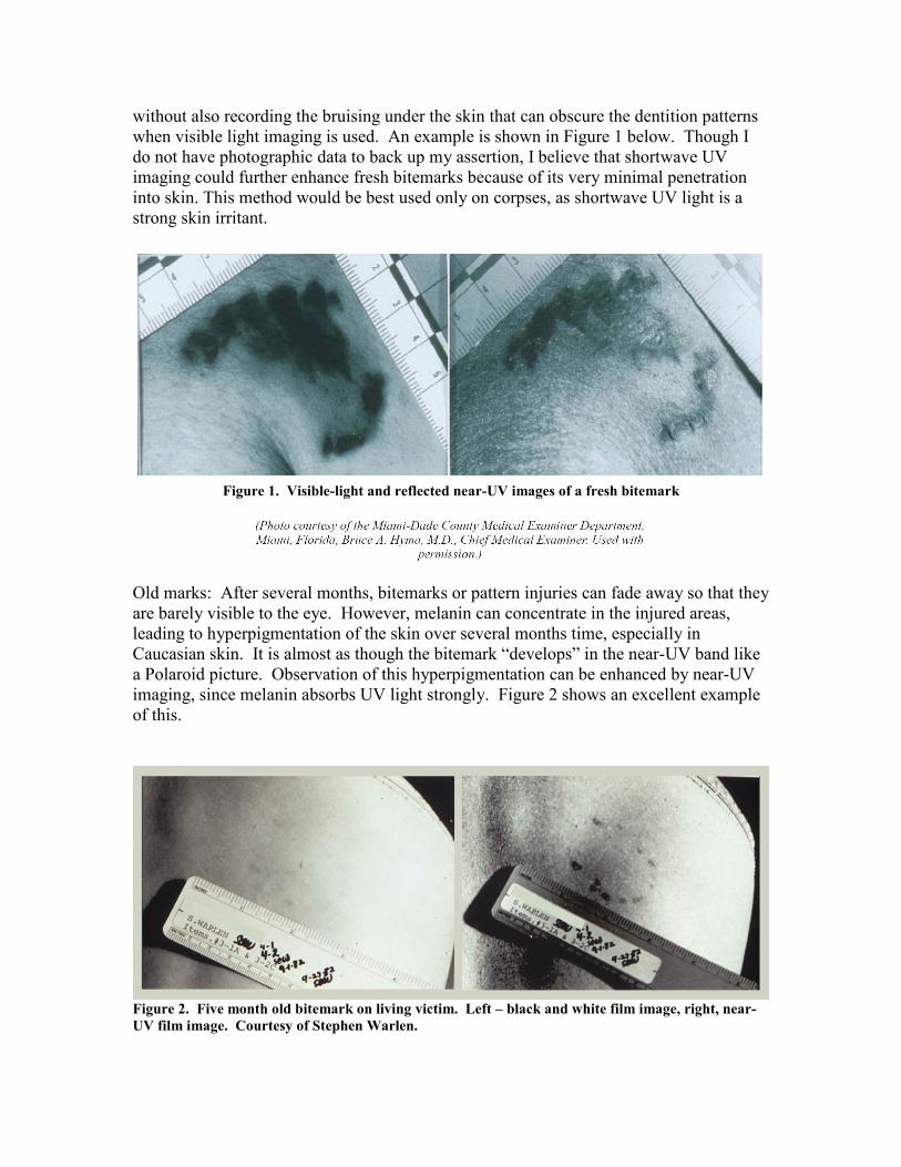
Figure 8 shows what happens at shorter wavelengths. The glass in the window is quite transparent to visible and near-UV light around 350nm, but becomes partially opaque in the near-UV down at 310nm. At the same time, a dried-out sweaty handprint becomes very apparent due to reflection by the minute salt crystals.
2 The shorter the wavelength, the easier it is to scatter light off of rough surfaces. Longer wavelengths average their interaction with surfaces over larger physical areas.
Figure 8. Latent handprint on glass window. Left – visible monochrome image. Middle – 350nm,
Right – 310nm image.
Imaging traces of certain substances on certain classes of surfaces:
Some examples of near-UV images showing trace materials are shown below. All the images are paired with a color reference image of the same scene. In every case, the anomaly is not apparent to the eye, to near-IR imaging or to UV fluorescence imaging, making the use of reflected-UV imaging an absolute requirement. Figure 9 shows a wall that has been recently repainted near ground level. The fresh paint is a polymer with pigment particles suspended in it. The polymer molecules absorb UV strongly, but after much exposure to the elements, it gradually oxidizes, weathers and picks up surface contamination, all of which makes it much more reflective to UV than the original fresh paint surface. In fact, it is primarily the ambient UV in sunshine that gradually degrades the organic polymer molecules, increasing UV reflectivity. Figure 10 shows this ageing paint phenomena on a car that has been in an accident. The driver’s side front fender was replaced after being freshly painted. Again, the fresh paint has not yet been weathered by exposure to UV light and the elements. This sort of image might be enough to get probable cause for a search warrant if the car was suspected of having been in a hit-and-run accident. A long-focal length lens can get this image even if the car is parked far up a driveway on private property. I took this picture on the streets of Santa Barbara where I live. The owner was very upset that I detected the rework on her car, as she was in the process of trying to sell it, and thought I might tell her prospective customers what I knew! Figure 11 is a shoemark made by stepping on an epoxy floor sealant that was still tacky. The traces of sealant are not apparent in the visible image, yet are obvious in the near-UV image. This was done by a floor installation workman at my house. I was tempted to show him the image and ask for a discount! Figure 12 is a toothpaste residue on a fake marble countertop made of Corian, which is made from a mixture of marble dust and

epoxy resin. The epoxy resin is highly absorbing to near-UV light but the toothpaste crystals reflect it. Figure 13 shows where spackle was applied to a drywall surface painted with white latex interior housepaint. Figure 14 is a two-for-one. I rubbed candlewax on the edge of a bathtub to see how it looked in the near-UV band. I expected the wax to reflect light differently which it does. But I also discovered a ring left by a glass container of hair dye. The ring was left by a houseguest at my friend’s house. He was asked not to put glass jars next to the tub but apparently disobeyed the host’s request! Figure 15 shows an oily stain of some unknown substance, and figure 16 shows cooking grease spills on a tile countertop. Every time I point my UV video camera at something, I seem to find evidence of other’s petty domestic infractions or uncover secrets! I dare not inspect hotel room surfaces too closely…
Figure 9. Freshly repainted stucco exterior wall. The fresh paint is dark in appearance. Left – color,
right – near-UV
Figure 10. A repainted front driver’s side fender on a Toyota Prius. Left – color, right – near-UV

Figure 11. Epoxy floor sealant shoemark on terracotta tile. Left – color, right – near-UV
Figure 12. Toothpaste stain on Corian countertop. Left – color, right – near-UV
Figure 13. Spackle on walls painted with white latex paint. Left – color, right – near-UV

Figure 14. Hair dye ring mark and candle wax trace on bathtub rim. Left – color, right – near-UV
Figure 15. Unknown oil stain on brown painted metal. Left – color, right – near-UV

Figure 16. Grease stains on countertop. Left – color, right – near-UV
Imaging changes in surface texture on smooth surfaces caused by physical contact:
The fine surface texture of an object can sometimes be imaged by reflected-UV methods where other methods fail or are impractical. As I described earlier, wave physics dictates that UV light is more readily scattered by tiny scratches and digs in a surface than is visible or certainly near-IR light. The rule of thumb is that UV enhances surface defects relative to visible light, while near-IR removes surface detail relative to visible light. This is why wedding photography in the near-UV band is never done! In fact, near-IR wedding photography is the new gimmick, as it makes everyone look 10 years younger in terms of skin appearance. Figures 15 and 16 show the effects of tiny changes in surface texture on reflected UV light.
Figure 17. Scratches in the varnished surface of a wooden drawer. Left – color, right – near-UV

Figure 18. Athletic shoe impression on freshly waxed floor. Left – color, right – near-UV
These last two applications for reflected-UV imaging seem to be some of the least explored areas of reflected-UV forensics imaging. I hope that will start to change after you read this paper.
Reflected-UV Imaging Equipment:
Digital Cameras for Reflected-UV Imaging:
The film methodology for reflected UV imaging in the near-UV band is well described in the literature and on the web and I will not discuss it here. If anyone wants more information, read my app note on the subject at http://www.uvcorder.com/products/app_note/ . The current focus of my efforts and others in this field is towards digital imaging and away from film. There are some digital SLR cameras with incidental UV response, but the standard for reflected UV and near-infrared imaging with a Digital SLR camera is the Fuji family of cameras which include the Fuji S-3 UVIR camera and the Fuji IS Pro. There are conversions available from www.maxmax.com but I have not personally tested any of them. I hear good things about them though.
Lenses for Reflected UV Imaging:
The standard for UV film photography has been the 105mm UV-Nikkor lens. This lens has not been manufactured by Nikon for many years and used examples are highly collectible and very expensive. Coastal Optics (now a part of JENOPTIK Optical Systems Incorporated) has built a clone of the 105mm UV Nikkor. It is an optically good lens system that is achromatic from 250 to 650nm with performance down into the shortwave UV band and color correction such that both visible and UV light focus at the same point. This correction enables one to pre-focus shots by eye without a UV pass filter in place, and then to install the UV pass filter and shoot properly-focused pictures. This is very nice, because it means one can shoot at low f/numbers, since the focus is already ideal. The system therefore does not require the high depth of fields one obtains with high f/numbers. The mechanical design of the JENOPTIK lens is not as good as the

original Nikkor lens, but it is serviceable. One of my graduate students at Brooks (Patrick Stanbro) has tested the 105mm Coastal UV lens and found it to be very effective, even down to 254nm. JENOPTIK has also produced a 60mm lens with color correction from the near-UV band to the near-IR band (310-1100nm). This lens has excellent optical and mechanical design, and should be considered by any forensics photographer that wants to shoot both near-IR and near-UV photographs. It is $4500, and may not be an option for many departments, which begs the question: can regular color lenses work for UV imaging? The answer is yes, and my students at Brooks and I have successfully used conventional 50mm Nikkor lenses for near-UV imaging. There are some SLR lenses out there that seem to work fairly well for near-UV imaging even though they were designed for color imaging. Finding them is largely trial and error – there are a number of blogs and forums that discuss which of these lenses work for near-UV. Older lenses with fewer elements are generally better in this regard. Paradoxically, less expensive color lenses that have single-layer magnesium fluoride antireflection coatings work better than expensive color lenses with multilayer dielectric AR coatings. Note that below about 350nm, no conventional glass lens system will be able to match the performance of the JENOPTIK or UV Nikkor lenses, which are made with special optical materials like calcium fluorite and fused silica that transmit shortwave UV light much better than conventional BK7 lens glass. We have also determined that color zoom lenses are quite poor in the near-UV band, because they have so many elements in them. There is only one commercial UV zoom lens system on the market today. It is made by Resolve Optics (http://www.resolveoptics.com/) and used in a Cherenkov radiation imaging system made by Channel Industries in Canada.
Filters for Reflected UV Imaging:
The Baader Venus filter is my preferred filter for near-UV imaging – it is the best of its kind by far with almost zero red leak. It is a combination of black glass filter material and an interference filter layer that blocks the red leak through the Schott UG-11 black glass. The Baader Venus filter has a bandpass of 325 to 390nm, as shown in the transmission curve (Fig.19). It is mounted in a 48mm ring which can be combined with a readily available 52mm stepdown ring so that it can be used on any lens with a 52mm ring thread, which includes the JENOPTIK/Coastal Optics lenses mentioned above. The Baader has a very tiny red leak peaked at 730nm, essentially zero visible light transmission and last but not least, quite decent transmission at the center wavelength of 370nm, as shown in Figure 6. When I try my red leak eye test, it is the only filter where an incandescent bulb appears to be very dim purple. Even though the UV is a small fraction of the brightness of the red and near-IR source emission, that is all that makes it through the filter. I see no reason one would want to use 18A filters, the PECA 900, or any other UV bandpass filters if the Baader is available – in fact the other filters in your lab should be labeled as having red leaks so they aren’t accidently used with a digital UV camera by some other hapless colleague. There is no technical advantage that I can think of to use those other filters, which generally always have a red leak. The only reason might be to

reproduce the exact setup of earlier UV photographic investigations that used film, or to study the characteristics of red leak photos mistakenly taken with the Fuji or other DSLR. The only other filter I have seen that is close to the characteristics of the Baader is a combination of the LDP Co. XNite-330 filter and their BP-1 filter which purports to block the red leak of the XNite-330. That filter combination is sold by www.maxmax.com and proved to be a disappointment when we tried it. The Baader is far better. The BP-1 leaks near-infrared light, and the only advice I got from the proprietor of LDP is to “buy another BP-1 and stack it on top”. That would be a poor idea, since stacking multiple optical surfaces with air gaps in between them is inviting ghost images due to Fresnel reflections. You would be better off to buy two Baaders for the price of an XNite-330 and two BP-1 filters. Finally, the XNite-330 reacts with moisture in the air, leading to an oxidized surface that does not help image quality whatsoever.
Figure 19. 2 Inch Baader Venus filter transmission curve. The leak at 1150nm is insignificant for silicon
sensors. Courtesy of Samuel Pellicori
Light sources for reflected-UV imaging:
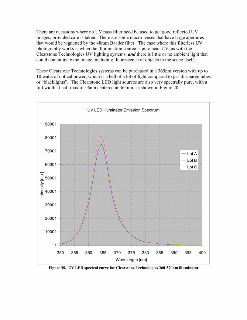
There are occasions where no UV pass filter need be used to get good reflected UV images, provided care is taken. There are some macro lenses that have large apertures that would be vignetted by the 48mm Baader filter. The case where this filterless UV photography works is when the illumination source is pure near-UV, as with the Clearstone Technologies UV lighting systems, and there is little or no ambient light that could contaminate the image, including fluorescence of objects in the scene itself. These Clearstone Technologies systems can be purchased in a 365nm version with up to 10 watts of optical power, which is a hell of a lot of light compared to gas discharge tubes or “blacklights”. The Clearstone LED light sources are also very spectrally pure, with a full width at half max of ~6nm centered at 365nm, as shown in Figure 20.
UV LED Illuminator Emission Spectrum
1
10001
20001
30001
40001
50001
60001
70001
80001
90001
350 355 360 365 370 375 380 385 390 395 400Wavelength [nm]
Inte
nsity
[a.u
.]
Lot ALot BLot C
Figure 20. UV LED spectral curve for Clearstone Technologies 360-370nm illuminator

Blacklight tubes are spectrally pure emitters in the 340-370nm band, but they aren’t very bright for photography, and they also emit some near-IR light at each end of the bulb where the incandescent hot cathode filaments shine through the purple waveshifting coating on the inside surface of the bulb. The last few inches of the ends should be covered up with black electrical tape to reduce potential contamination of the desired near-UV image, though I cannot guarantee that this treatment will not shorten the life of the lamp due to increased heating. My students at Brooks and I have taken photos with the Fuji, a color Nikkor lens with a Baader filter and a bank of eight 18 inch blacklight tubes, and have been a little disappointed about how dim the lights were, but they do work. The Clearstone light is the way to go if you have the means. Note that the wavelength of the UV illumination does affect the appearance of many UV images. I have found that forensic phenomena often are more apparent with a 365nm LED illuminator than with the much more common 396nm LED light sources. Beware of any vendor of UV LED illuminators that is not explicit about the wavelength of their lights. It is very important to use the right wavelength of UV light for forensic imaging. There are historical precedents that 365nm is THE wavelength for near-UV forensic imaging. There is a considerable body of published imagery taken right around this wavelength. The legacy 18A filters have peak transmission at this wavelength, as do the Wood’s lamps in common use as a near-UV source. These lamps use a medium pressure mercury discharge lamp combined with a black Wood’s glass filter. The principal spectral line of medium pressure mercury vapor is centered at 365nm. If the Clearstone source is used without a Baader or other UV pass filter on the camera lens, care must be taken to avoid subject matter that has fluorescence in either the visible band or near-IR band, which will degrade the purity of the desired near-UV image. The only reason that I can think of to not use the Baader filter is to increase the exposure by about 20%, which is about how much the Baader reduces in-band light signals (from 100% to 80% as shown in Figure 17). A 20% gain in light is only a fraction of a stop though, so one might as well always use the Baader to prevent any possibility of visible or near-infrared fluorescence contamination.
Ultraviolet flash units:
Any flash unit used for near-UV imaging should have a xenon strobe lamp that is purposely lacking the pale yellow polymer filter coating that normally absorbs the copious near-UV emission which is undesirable to color photographers. These bulbs are available as special order items. There are also integrated camera flash units designed to have very little visible light emission. The Quantum QFlash80 unit with its black glass filter on it is one such example3. I have determined that this filter has a large red leak by imaging through the detached filter with a near-IR video camera. Therefore, if the Quantum flash is used to take near-UV photographs, one will get near-IR contamination in the image unless a Baader filter is used, because a xenon flash spectrum is rich in red and near-IR emission.
3 See Quantum Instruments Inc at www.qtm.com for more information.

That flash filter was really intended for UV fluorescence photography where a red leak is not generally important. In that case, the UV flash excites visible fluorescence in the scene which is recorded by a standard color camera equipped with a UV blocking filter. I would not use the black glass filter on the Quantum flash when using the Baader filter because you don’t need it – the Baader does all the filtering. All the flash filter is doing is reducing the brightness of the UV flash of light that you want. Why block the “good stuff” if you don’t have to? The Baader takes care of out-of-band light. The only reason to leave on the black glass filter is to reduce the visible light signature, which might be useful if the bright visible component of the flash was disturbing to other investigators in the area. The Baader could be installed on the QFlash80 and give it spectrally pure UV performance. This might be worth trying with an unfiltered lens, because then the shots could be composed and focused by eye, and as long as the scene did not reflect or emit visible or near-IR light, the pictures would still be true near-UV. My recipes for successful near-UV photography with a Digital SLR camera include:
Recipe 1 – outdoors in the daytime
1. Fuji S-3 UVIR camera 2. JENOPTIK 60mm UV-VIS-NIR lens or 105mm UV-Vis lens 3. 2 inch Baader Venus filter 4. Direct sunlight
Recipe 2 – indoor close-up
1. Fuji S-3 UVIR camera on a tripod 2. JENOPTIK 60mm UV-VIS-NIR lens or 105mm UV-Vis lens 3. 2 inch Baader Venus filter 4. An array of discharge tube type blacklights
Recipe 3 – using flash illumination
1. Fuji S-3 UVIR camera 2. JENOPTIK 60mm UV-VIS-NIR lens or 105mm UV-Vis lens 3. 2 inch Baader Venus filter 4. Quantum QFlash without a black glass UV pass filter
Recipe 4 – indoors, large field of view
1. Fuji S-3 UVIR camera 2. JENOPTIK 60mm UV-VIS-NIR lens or 105mm UV-Vis lens 3. 2 inch Baader Venus filter 4. Clearstone Technologies 365nm source
The UVCorder and UVScanner:
One of the major drawbacks to the Fuji UVIR camera systems is that the live preview feature in the Fuji system is all but useless for near-UV imaging. The live preview can be started only when the lens is set to the maximum f/stop setting. Only then can one open up the aperture to admit more light to brighten the live preview image. The video only persists for 30 seconds, and the activation of the feature requires multiple awkward button pushes on the S-3 UVIR. Finally, the screen is small and it is hard to tell if the focus is correct. I am not sure how it behaves with the JENOPTIK lens – when we used the lens it was on a conventional film camera with Tri-X panchromatic film. The Fuji’s live preview image is very dim and hard to see unless the UV light levels are very high, which is hard to achieve unless one uses a very bright UV source like the Clearstone illuminator. One can also cover the camera and one’s head with a black cloth but that is a nuisance. The dimness is because the effective shutter speed of the camera in live preview mode is about 1/10 of a second. The Fuji is not very responsive to near-UV light, and so the live image is quite dim at those relatively short shutter speeds. The Fuji also eats batteries like mad when the Live Preview mode is used often. I recommend that it be tethered to the included AC power supply when used in the lab. Given how hard it is to use the live preview mode just to get a still image out of the Fuji, it is nearly impossible to use the camera as an imaging scope to find UV phenomena on a body or other forensic object of investigation. That is where the UVCorder comes in. The UVCorder, shown in Figure 21, is a complete near-ultraviolet digital video camera system that is hand-held and battery powered. The live preview mode is always on, and the battery life is measured in hours. One can record the video to a mini-DV tape in the camcorder, and the camera can also be switched to record in color, since the platform for the unit is a consumer camcorder. Our customers are very happy with the product, and have used them to record all kinds of reflected UV phenomena, including skin anomalies. I have rapidly scanned an entire room in a few minutes to find surface anomalies such as spackle covering holes in the white painted sheetrock on the walls. The UV module on top can also be detached and mounted on a tripod or handheld, with the video output connected to a monitor or other recording device.

Figure 21. Second generation UVCorder system
The UVCorder has automatic gain control, making it very easy to get an image provided that there is sufficient UV light present. It has special filtration on it that makes it quite unresponsive to visible or near-infrared light. The only controls that are needed are the focus and f/stop setting of the lens, which are both easy to do with one hand. Oculus Photonics launched a new product in March of 2010 called the UVScanner, shown in Figure 22. It is a handheld UV imager that allows the user to see the UV image even in the presence of bright ambient light. The images are presented on dual 640x480 backlit LED displays that are shielded by rubber eyecups that seal to the face. The UVScanner has dual 396nm LED illuminators on top, enabling active UV imaging out to about 15 feet.

Figure 22. Oculus Photonics UVScanner
The UVScanner is used to search for UV phenomena. Once an interesting UV scene is located, the user can then photograph the phenomenon with the Fuji S-3 UVIR or other UV-sensitive DSLR camera. The scanner is more convenient than the UVCorder in some cases, as the LCD screen on the UVCorder is sometimes hard to see in bright ambient light conditions, and the eyepiece in the back of the UVCorder has fairly low resolution. The UVScanner does not record video, though it has a video out connector that enables recording of the video stream to a camcorder or other device. Finally, the UVScanner sits close to the chest on its harness, making it easy to carry around on one’s person while also handling a Fuji S-3 or other UV-equipped DSLR.
Summary: These are the important points I hope you have taken away from this paper:
• Reflected-UV imaging is a powerful tool for the forensic investigator, but it has historically suffered from a lack of knowledge and understanding of the technique and equipment and some real or perceived barriers to entry.

• Digital cameras can be used for reflected-UV imaging, but they must be carefully selected and used with the proper lighting and filtration to avoid the dreaded red leak that can unintentionally make an image a near-IR one instead.
• The full range of applications for reflected-UV imaging in forensics have not been well understood or appreciated in the past. Some of the new applications are made possible by the use of UV video imaging systems in parallel with UV still cameras. These applications warrant further study by forensic investigators.
• A powerful combination of reflected-UV imaging tools consists of:
1. The UVCorder or UVScanner handheld system or some near-UV video system to rapidly scan an area for reflected UV anomalies.
2. The Fuji system (I like Recipe 4) to shoot these areas of interest at much
higher resolution.
Appendix:
Measuring the spectral response of a Fuji S-3 UVIR camera:
I am fortunate to have access to a spectral response system that I use for determining the spectral response of infrared cameras at FLIR, my main employer. The system consists of a scanning monochromator, broadband light sources and calibrated detectors to calibrate the monochromator output. The instrument produces a pencil beam of light that is narrow in wavelength range and that can be adjusted to any center wavelength value across the spectrum that the UVIR camera can possibly image in, from 300nm to 1200nm and beyond. Moreover, the intensity of this beam can be measured at each wavelength, making it a probe for a camera’s spectral response. I took images of the beam by shining it directly onto the sensor of the UVIR camera, with no lens installed. The images were then processed in the Fuji software called Hyper-Utility2. This utility enabled me to measure the digital counts in a region of interest drawn in the image of the monochromator beam. Figure 23 shows a screen shot of the software with a measurement of the red blue and green channels of the image of the monochromator beam set at 350nm. The red channel is by far the brightest in the set, which is due to the fact that 350nm light aliases as 700nm light in the red Bayer filters.

Figure 23. Fuji S-3 UVIR raw image of 350nm beam
When the beam is set to 400nm, the blue channel dominates, as shown below in Figure 24.

Figure 24. Fuji S-3 UVIR raw image of 400nm beam
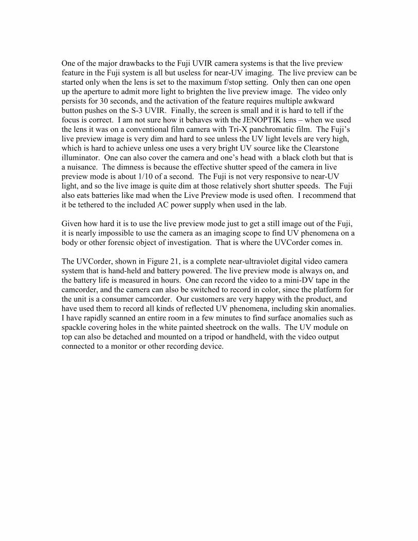
The 400nm beam is closer to the bandpass of the blue Bayer filters. In every case, there is only a very weak signal in the green channel. I took photos of the beam at 10nm intervals from 400nm down to 300nm. As the wavelength got shorter, the shutter open period needed to be increased to compensate for the reduced spectral response. I also recorded the beam power in microwatts at each wavelength using a calibrated silicon detector made by Thermo-Oriel. The mean digital count value in the centroid of the beam spot was then scaled by the beam power and the shutter period, giving a relative spectral response, as shown in Figure 25. The results suggest that the red channel is superior in terms of available signal below 380nm wavelength. I am not entirely comfortable with the accuracy of these measurements, especially below 350nm. The monochromator has a relatively weak UV signal since the 3000K tungsten light source has a steeply falling near-UV spectral radiant emittance as the wavelength gets shorter. I can see some visible light emitted from the monochromator. This is white light reflecting around inside the monochrmator assembly, and it definitely affects the purity of the beam and the accuracy of the measurement. I really need a deuterium lamp
to properly inject UV light into the monochromator. These lamps put out a substantial amount of broadband UV light and relatively little visible or near-IR light.
Relative Photon Spectral Response of Red and Blue Channels
Fuji S-3 UVIR camera with no lens
Near-UV waveband
0.00
0.10
0.20
0.30
0.40
0.50
0.60
0.70
0.80
0.90
1.00
290 310 330 350 370 390 410
Wavelength (nm)
Figure 25. Relative photon spectral responses of red and blue channels in the Fuji S-3 UVIR camera
Which color channel to use to get a reflected-UV image out of a color DSLR?
The Bayer filters are certainly a nuisance when it comes to shooting near-UV imagery. They cut down the UV light signal, especially the green filters which account for 50% of the filters in the pattern. Experiment has shown me that the choice of channel is not always obvious. The best near-UV image is sometimes extracted from the red channel, and sometimes from the blue channel, but never from the green channel, at least on the Fuji S-3 UVIR. If the UV illumination is fairly broadband, as with a Baader filter which is 325nm to 390nm, the choice of color channel will tend to bias the resulting UV image to higher or lower wavelengths. For instance, use of the Baader on the Fuji in full sunlight illumination tends to give images that have about equal measures of red channel signal and blue channel signal. The user can select the red or the blue to maximize contrast in the image. Both are near-UV, but there is a bias towards either the shortwave side (with the red channel) or longwave side (with the blue channel) of the Baader passband. I have found that the red channel may sometimes have more overall signal, but sometimes it gives less contrast due to what I think is veiling glare, a phenomenon whereby lens elements imperfectly AR coated for the waveband reflect light around inside the lens assembly, resulting in a uniform haze over the image.

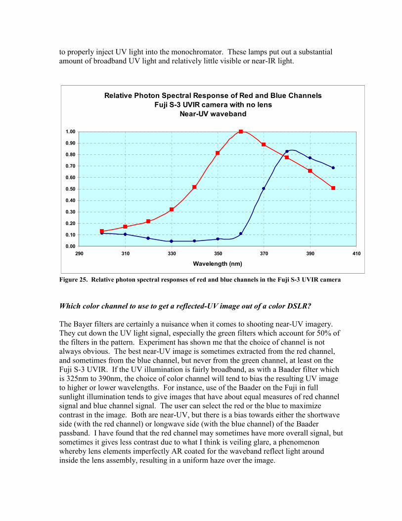
Figure 26 shows the output of the Fuji and the images from the red and blue channels. The scene is a piece of white printer paper with a sunscreen handprint on it. The illumination source is a blacklight which peaks in brightness at 365nm. I photographed it with the UVIR camera, a Baader filter and a conventional Nikkor color lens. The resulting near-UV image looks magenta, a combination of red and and blue. The two viable color channels (Figures 27 and 28) give nearly identical results in terms of yielding a high-contrast image of the handprint in the near-UV band. The green channel yields a decent near-UV image as well, but since there are several stops less signal it is not recommended.
Figure 26. RGB composite image of handprint on paper. Illumination is 365nm.
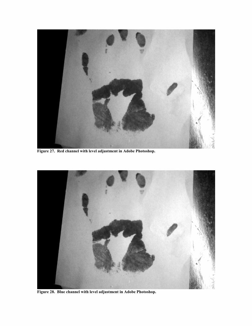
Figure 27. Red channel with level adjustment in Adobe Photoshop.
Figure 28. Blue channel with level adjustment in Adobe Photoshop.

Figure 29. Green channel with level adjustment in Adobe Photoshop. The green channel had
significantly less signal that the red or blue channels.