refining the dp watch circle 11 oct 06 - dynamic...
TRANSCRIPT
Gabriel Delgado-Saldivar The Use of DP-Assisted FPSOs for Offshore Well Testing Services
DYNAMIC POSITIONING CONFERENCE October 17-18, 2006
Operations and Procedures
Refining the DP Watch Circle
Lew Weingarth Transocean, Inc.
Lew Weingarth, Transocean Operations and Procedures Refining the DP Watch Circle
MTS DP Conference Houston Page 1 16-17 October 2006
Refining the DP Watch Circle
Abstract
This paper will discuss how the Watch Circle has evolved into a detailed technical analysis ofoperating limitations. Today, the Well Specific Operating Guideline is used to assess all risks tothe vessel, determine which are the limiting factors, and provide a simple set of guidelines bywhich the DPO can minimize risk to personnel, environment, and equipment no matter whatsituation arises.
1.0 Introduction
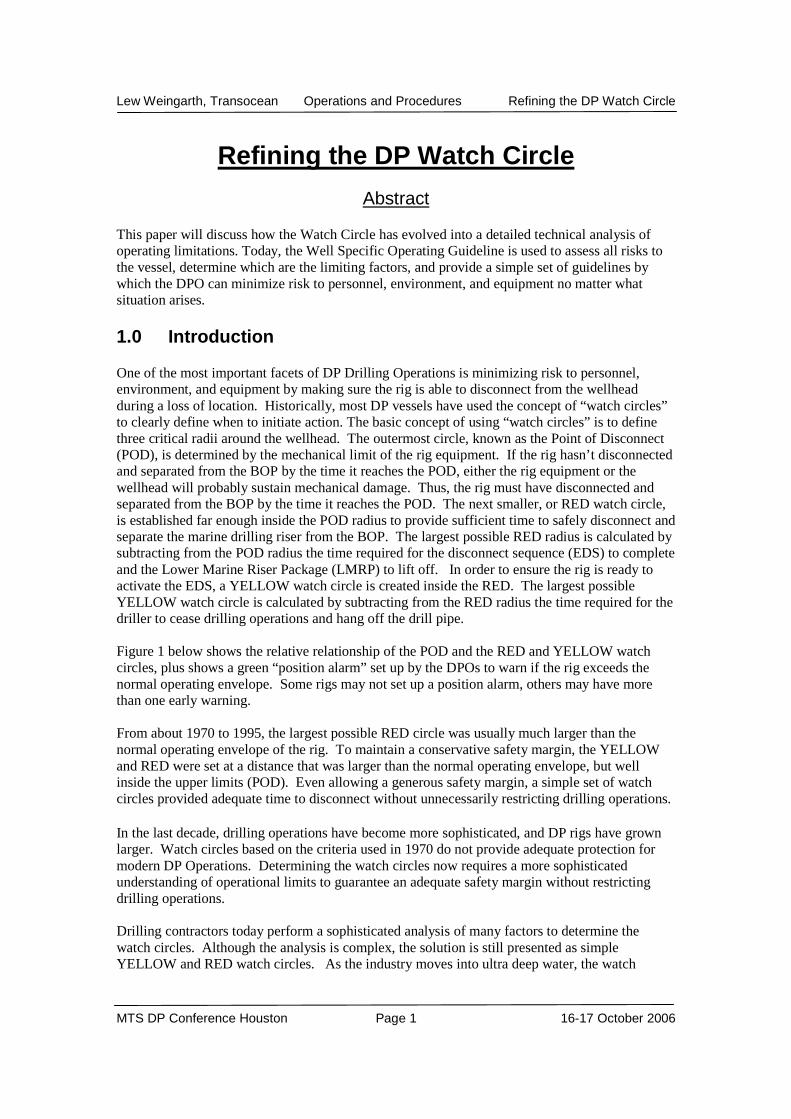
One of the most important facets of DP Drilling Operations is minimizing risk to personnel,environment, and equipment by making sure the rig is able to disconnect from the wellheadduring a loss of location. Historically, most DP vessels have used the concept of “watch circles”to clearly define when to initiate action. The basic concept of using “watch circles” is to definethree critical radii around the wellhead. The outermost circle, known as the Point of Disconnect(POD), is determined by the mechanical limit of the rig equipment. If the rig hasn’t disconnectedand separated from the BOP by the time it reaches the POD, either the rig equipment or thewellhead will probably sustain mechanical damage. Thus, the rig must have disconnected andseparated from the BOP by the time it reaches the POD. The next smaller, or RED watch circle,is established far enough inside the POD radius to provide sufficient time to safely disconnect andseparate the marine drilling riser from the BOP. The largest possible RED radius is calculated bysubtracting from the POD radius the time required for the disconnect sequence (EDS) to completeand the Lower Marine Riser Package (LMRP) to lift off. In order to ensure the rig is ready toactivate the EDS, a YELLOW watch circle is created inside the RED. The largest possibleYELLOW watch circle is calculated by subtracting from the RED radius the time required for thedriller to cease drilling operations and hang off the drill pipe.
Figure 1 below shows the relative relationship of the POD and the RED and YELLOW watchcircles, plus shows a green “position alarm” set up by the DPOs to warn if the rig exceeds thenormal operating envelope. Some rigs may not set up a position alarm, others may have morethan one early warning.
From about 1970 to 1995, the largest possible RED circle was usually much larger than thenormal operating envelope of the rig. To maintain a conservative safety margin, the YELLOWand RED were set at a distance that was larger than the normal operating envelope, but wellinside the upper limits (POD). Even allowing a generous safety margin, a simple set of watchcircles provided adequate time to disconnect without unnecessarily restricting drilling operations.
In the last decade, drilling operations have become more sophisticated, and DP rigs have grownlarger. Watch circles based on the criteria used in 1970 do not provide adequate protection formodern DP Operations. Determining the watch circles now requires a more sophisticatedunderstanding of operational limits to guarantee an adequate safety margin without restrictingdrilling operations.
Drilling contractors today perform a sophisticated analysis of many factors to determine thewatch circles. Although the analysis is complex, the solution is still presented as simpleYELLOW and RED watch circles. As the industry moves into ultra deep water, the watch
Lew Weingarth, Transocean Operations and Procedures Refining the DP Watch Circle
MTS DP Conference Houston Page 2 16-17 October 2006
circles are steadily “closing in”, leaving less room before disconnect {this will be explainedlater). Today, for some operations the theoretical maximum RED is not significantly larger thanthe Normal operating envelope.
An unexpected disconnect costs about $1 million just for lost drilling fluids, and much more ifspread costs are included. If a disconnect results in a delay in the start of oil production, the cost[of disconnect] is even larger. With $60/bbl oil, anything that causes a delay before the oilcompany brings a large deepwater field to market may represent significant unearned revenue.Clearly, there is sufficient financial incentive to see if we can improve performance.
This paper will discuss how the Watch Circle has evolved into a detailed technical analysis ofoperating limitations, how the output of this detailed analysis is presented as simple and clearguidelines for the DPO, and some ideas for further evolution of the watch circle as the industrymoves into deeper water and harsher environments in our search for oil.
Figure 1 - Graphical Representation of Watch Circles
2.0 Origin of the DP Watch Circle
In order to maintain control of well bore fluids in wells on the seabed in deep water, the well boremust be extended up to the rig, where conventional drilling technology can be utilized. To makethis possible, a well is constructed in the following order.
1. A wellhead is cemented into the sea floor
Lew Weingarth, Transocean Operations and Procedures Refining the DP Watch Circle
MTS DP Conference Houston Page 3 16-17 October 2006
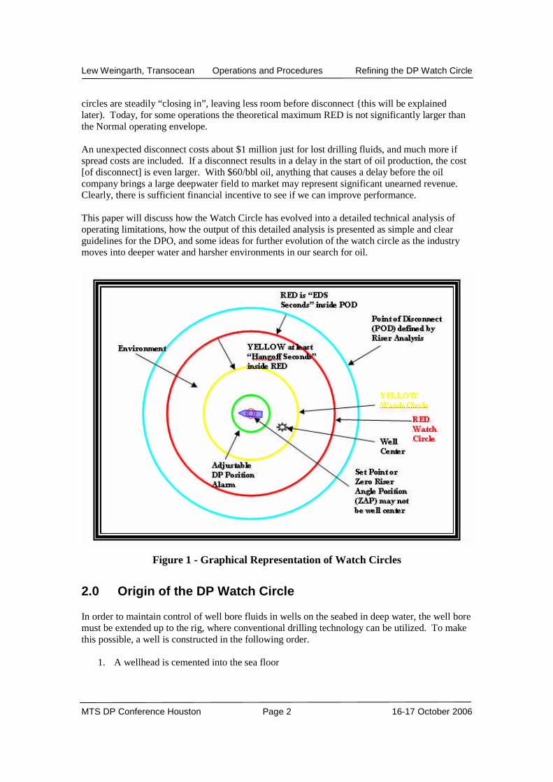
2. A large set of high pressure valves (known as a Blow Out Preventer or BOP) is placed ontop of the wellhead. The BOP contains valves that seal the open well bore, blades thatcan sever the drill pipe, and hydraulic connectors to allow separation of the marinedrilling riser from the BOP if the rig loses location.
3. A large diameter steel pipe, ~ 48 inch OD when fully dressed with hydraulic lines andfoam floatation (known as a marine drilling riser, or riser for short) is run from the drillfloor to the well control equipment (BOP) on the sea floor. The riser is used to extendthe well bore from the sea floor to the rig.
4. Flexible connections are installed at the top and bottom of the marine drilling riser inorder to allow the rig a limited range of motion without bending the pipe. These arecalled “flexjoints” and typically allow about 10 degrees of bending at the top and bottomof the riser.
5. To allow for vessel heave, a telescopic joint (or slip joint) is installed at the top of themarine drilling riser. Typically, slip joints are produced with at least 10 meters of stroke.Some newer units have 20 meters of stroke.
6. Large hydraulic cylinders, known as “riser tensioners”, are installed between the rig andthe riser (just below the slip joint) to maintain the entire length of the riser in tensionwhile the rig rides over waves.
Figure 2 - Drilling Rig and Associated Equipment
3.0 Evolution of Watch Circles 1970-1995
The first DP Oil Exploration Drilling Rig was the Sedco 445, which started drilling about 1970.Deep water in 1970 was much shallower than today. In 1974 the 445 set a world record bydrilling in 600 M of water – today we routinely anchor rigs in deeper water. The limiting factor
Lew Weingarth, Transocean Operations and Procedures Refining the DP Watch Circle
MTS DP Conference Houston Page 4 16-17 October 2006
for station keeping for these early ships was usually the maximum angle at which the riserconnector [to the BOP] of 1970 would release, about 5 degrees or about 8.7% of water depth. DPsystems of the time typically maintained a Normal operating envelope well under 1% of waterdepth. This allowed a lot of range for defining the RED watch circle. To allow time to releasefrom the wellhead, the 20-30 second Emergency Disconnect Sequence (EDS) was activated atabout 5% of water depth, or 3 degrees of riser angle. The RED watch circle was commonly set to5% of water depth. To provide time for the driller to pick the drill pipe up off bottom andprepare for a clean disconnect, a second, “YELLOW” watch circle was set at half or two thirds ofthe RED diameter. As other industries adapted DP controls to their vessels, most adopted theRED and YELLOW watch circles, or something similar.
From 1970 to 1985 the industry moved into deeper water as technology improved, passing 1,200meters by 1977 and 2,000 meters by 1985. Advancement of DP and rig equipment in this periodwas evolutionary rather than revolutionary. Drilling rigs in 1985 used almost the same drillingand DP equipment as in 1970. Usually, riser angle or riser tensioner stroke still established thelimiting criteria, so watch circles in 1985 were similar to 1970.
Marine seismic analysis in 1970 was less sophisticated than today, thus [in the 1970s] it wasactually fairly rare for DP rigs to drill into hydrocarbon reservoirs in deep water. With the maingoal [of this period] being development of deepwater drilling technology rather than developmentof deepwater reservoirs, BOP stacks in the 1970s tended to be much lighter, shorter, and simplerthan current equipment.
The period 1985-1995 was an “economic dark age” for the offshore drilling industry as depressedoil prices limited offshore drilling budgets. DP technology stagnated because there wasn’tenough profit to justify improvements (the water depth record only advanced from 2,000 metersto 2,300 meters between 1977 and 1995). Between 1985 and 1995 little changed in DP.
While the drilling industry was struggling along in survival mode, cheap and powerful computersrevolutionized the seismic industry. 1985-1990 was a “golden age” for seismic companies, whoused cheap and fast new computer technology to dramatically improve their ability to identify oilreservoirs. The major oil companies recognized the cost saving they could achieve by avoidingdrilling dry holes and poured R&D money into improving the success rate of seismic surveys.
By 1990, advanced seismic techniques allowed companies to identify hydrocarbon reservoirswith 10 times the “find ratio” of 1970. Though oil prices were still weak, enough attractivedeepwater prospects were identified to keep the DP industry alive. Improved seismic made itmore likely that the rig would drill into an oil reservoir, thus more likely that a loss of locationcould have environmental consequences. In response, watch circles were reviewed to inreaseconfidence that the well was secured before disconnect, and the industry began discussing theneed to add more functions to the BOP.
4.0 Evolution of Watch Circles 1995 to Present Day
By 1995, economic recovery had increased demand for oil Tax incentives for US offshore oilproduction combined with economic recovery revived interest in offshore drilling in the USGoM. Similar tax incentives and economic conditions revitalized the North Sea. At the sametime, advanced seismic techniques identified immense hydrocarbon potential in the deepwaterGoM, offshore West Africa, and Brazil. Economic recovery, tax cuts, seductive seismic data,and increased oil demand set the stage for increased deepwater exploration.

Lew Weingarth, Transocean Operations and Procedures Refining the DP Watch Circle
MTS DP Conference Houston Page 5 16-17 October 2006
By 1997 economic recovery and oil demand were strong enough that the industry began to build anew series of deepwater DP drilling rigs, designed for up to 3,000 meters of water. By 2000these new rigs were hitting the market, and encountering new challenges. The new deepwaterrigs required that more factors be considered to establish the limits for watch circle determination.With these new deepwater rigs, riser angle or riser tensioner stroke were rarely the limiting factor.
On the new deepwater rigs, riser tensioner pulldown and slip joint strokeout were usually reachedbefore maximum riser angle. Deep water operations require a longer and heavier marine drillingriser to handle the higher loadings. Riser tensioner capacity must be increased to support theheavier riser. At the same time, companies asked for more capability from BOP stacks, whichmade them taller and heavier. Taller BOPs and larger riser tensioners required taller and heavierdrilling substructures, which in turn required larger rigs. Also, new generation BOP controlsystems often had EDS sequences more than twice as long as in 1970.
Taller drill floor structures raised the height of the upper flex joint above the keel, so unless themoonpool was increased in size, riser contact with the moonpool often became the limit. Higherriser tension at the BOP, combined with taller BOPs, put more stress on the wellhead and surfacecasing. It was now possible for the surface casing to sustain permanent damage before reachingthe operating limit of the riser connector.
Larger, heavier vessels drift more slowly when DP fails, but inertia works both ways, largervessels are harder to stop once motion starts. With larger vessels it became more likely that avessel could achieve sufficient velocity, while still inside the RED, so that crossing the REDwould be unavoidable. Thus, it became more important to consider velocity when determiningthe watch circles.
The simple equations of 1970 no longer worked. Determining a valid watch circle now requireda sophisticated computer to sort through all the variables and find the most restrictive.Calculating watch circles today is more complex than in the past. A wide range of factors mustbe considered.
Considerations for calculating a modern watch circle include:
Riser angle (riser connector limit) EDS time Flex joint (v. ball joint) increases moment on wellhead Moonpool contact Upper flex joint angle Riser tensioner pull down Slip Joint Extension Wellhead/casing yield point Seafloor soil yield point Rig velocity Special equipment / Operations such as production testing
Figures 3 and 4 show how careful moon pool design allows a large upper riser angle limit.

Lew Weingarth, Transocean Operations and Procedures Refining the DP Watch Circle
MTS DP Conference Houston Page 6 16-17 October 2006
Figure 3 - Wide Moonpool Allows Figure 4 –Narrow Moonpool Limits Upper Angle
Large Upper Angle
In addition to these physical limits, environmental conditions must be included in the calculation,in particular if the operating region is prone to large variations in wind or current. Also, blackoutrestart time for the power plant is a major consideration, e.g. the time to reach terminal velocitymay be less than the time to restart the power plant and stop vessel motion.
Although the limit might be determined by any of these factors, the DPO cannot rememberdifferent limits for all these factors. The watch circles must be simple and clear.
5.0 Detailed Analysis
Today a detailed engineering analysis of all the physical limits is performed to determine whichlimits affect the rig first. In order to assure a comprehensive analysis, the full range of weatherconditions, currents, waves, wind, and heave for the drilling location, as well as the worst casesingle failure must be defined. If there is more than one EDS sequence, the analysis must beperformed for the EDS sequence that is enabled. These data are subjected to a sophisticatedanalysis that determines the limits for all parameters.
This analysis can be performed: on the rig (with specialized software) on shore by a dedicated department outsourced to a third party.
All three methods have advantages. Analysis on the rig provides the fastest answer if anunanticipated situation arises, but runs a higher risk of mistakes if the user isn’t familiar with theanalysis tool. Also, the analysis tool must contain sufficient expert knowledge to guide the userfor all possible situations. Outsourcing to a third party has the advantage that most third parties

Lew Weingarth, Transocean Operations and Procedures Refining the DP Watch Circle
MTS DP Conference Houston Page 7 16-17 October 2006
may have several phDs on staff, which should produce a high quality analysis. Thedisadvantages are slower response time and high cost, plus the quality of the analysis is highlydependent on the quality of data provided to the consultants. Analysis in house by dedicatedEngineers is somewhere in the middle. The advantages are that delivery can be fairly easilyadjusted to the rig’s urgency, good quality control, and is the best method to assure the analystunderstands any special circumstances related to a particular rig design. The disadvantages ofperforming the analysis in house are that a consultancy firm may have stronger tools and deeperskill, plus, for a small company, the cost of maintaining internal expertise may be as high asoutsourcing.
The analysis outputs only one set of watch circles, those determined from the physical limitwhich is reached first. Similar to the simple watch circles of 1970, the constraining limit istranslated into a radius around the set point position.
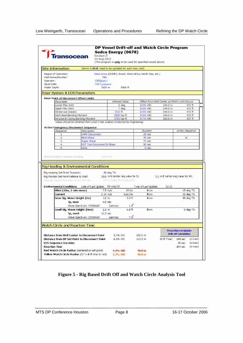
The next figure shows the user interface of a typical rig-based analysis tool. While the analysis isquite complex, requiring several minutes of calculation, the user interface is kept very simple.All user changeable inputs are color coded and clearly marked. The output of the softwareanalysis is presented clearly.
Lew Weingarth, Transocean Operations and Procedures Refining the DP Watch Circle
MTS DP Conference Houston Page 8 16-17 October 2006
Figure 5 - Rig Based Drift Off and Watch Circle Analysis Tool
Lew Weingarth, Transocean Operations and Procedures Refining the DP Watch Circle
MTS DP Conference Houston Page 9 16-17 October 2006
6.0 WSOG
In addition to calculations that determine when the rig must physically disconnect from the wellto prevent damage, every location must also consider operational concerns (explained in detailbelow):
The rig may need to restrict operations based upon excessive risk - factors separate from thephysical limits defined in the RED and YELLOW watch circles.
This analysis is known as the “Well Specific Operating Guidelines”, or WSOG. The WSOGcontains the RED and YELLOW as determined by the watch circle analysis, plus a set ofguidelines based upon operational considerations. These may include:
If the DP system is unable to hold station without a gyrocompass, the WSOG will containa line item that specifies an immediate RED if all the gyrocompasses fail, and perhaps aYELLOW if all but one fail.
If the client wants to run a tree or some other non-standard equipment, the rig willexamine this operation and modify the watch circles based on how quickly the non-standard equipment can be secured and released.
If the well location is close to a sea floor obstruction, either man made or natural, theWSOG may specify not running casing or suspending drilling operations during periodswhen ambient current and wind would push the rig in that direction.
In the GoM the WSOG may contain special considerations for hurricanes. Simultaneous operations (SIMOPS) by another vessel alongside the drilling rig may
require special YELLOW and RED conditions related to risks associated with theSIMOPS.
Transocean’s patented dual-activity technology, e.g. drilling one hole while runningcasing in another, may impose additional restrictions (limited heading changes or smallerwatch circles).
Special operations such as offloading crude oil while drilling, or production testing mayimpose additional restrictions (limited heading changes or smaller watch circles).
The main goal of the WSOG is to define operations and risk in sufficient detail to provide the rigwith a clear set of guidelines for any situation that arises.

Lew Weingarth, Transocean Operations and Procedures Refining the DP Watch Circle
MTS DP Conference Houston Page 10 16-17 October 2006
Figure 6 – Example of a WSOG Format
Lew Weingarth, Transocean Operations and Procedures Refining the DP Watch Circle
MTS DP Conference Houston Page 11 16-17 October 2006
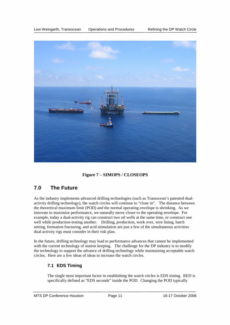
Figure 7 – SIMOPS / CLOSEOPS
7.0 The Future
As the industry implements advanced drilling technologies (such as Transocean’s patented dual-activity drilling technology), the watch circles will continue to “close in”. The distance betweenthe theoretical maximum limit (POD) and the normal operating envelope is shrinking. As weinnovate to maximize performance, we naturally move closer to the operating envelope. Forexample, today a dual-activity rig can construct two oil wells at the same time, or construct onewell while production-testing another. Drilling, production, work over, wire lining, batchsetting, formation fracturing, and acid stimulation are just a few of the simultaneous activitiesdual-activity rigs must consider in their risk plan.
In the future, drilling technology may lead to performance advances that cannot be implementedwith the current technology of station keeping. The challenge for the DP industry is to modifythe technology to support the advance of drilling technology while maintaining acceptable watchcircles. Here are a few ideas of ideas to increase the watch circles.
7.1 EDS Timing
The single most important factor in establishing the watch circles is EDS timing. RED isspecifically defined as “EDS seconds” inside the POD. Changing the POD typically

Lew Weingarth, Transocean Operations and Procedures Refining the DP Watch Circle
MTS DP Conference Houston Page 12 16-17 October 2006
requires huge investments in capital and time, e.g. designing a new wellhead or new riserstring. Shortening the EDS sequence can usually be done cheaper and faster. Forexample, if Rig A has an EDS time of 80 seconds, which is not unusual these days, andRig B has an EDS time of 25 seconds, also not unusual, and they both have the samePOD of 6.3% of water depth, the slower EDS time results in dramatically reduced REDwatch circle for the rig with the slower EDS. Using numbers from a typical analysis, wefind that Rig B would have a RED watch circle of 90 meters, but on the same well Rig Awould have a RED watch circle of only 50 meters. Assuming a YELLOW of 70% ofRED, Rig A will secure the well and cease operations at 35 meters, while Rig B wouldcontinue operations to 63 meters. A sudden shift in strong current, common in manyplaces on earth, can easily cause a temporary offset of 20-30 meters. To preventinterruptions, RIG A must set the YELLOW at the theoretical maximum, while RIG Bcan set theirs a comfortable 30 meters inside the limit. Shortening the EDS time wouldprevent interruption of revenue at no cost in DP performance, and with reduced risk.
7.2 Stack Angle
In deep water, the limiting factor in most cases is the soil strength, and soil strength isessentially described in terms of how large of a stack angle the rig can tolerate withoutdamaging the soil/casing. Because flex joints are relatively stiff, when a rig offsets muchof the bending force is transferred to the stack. As we move into 4,000 meters of water,likely with even heavier BOPs than we have today, stack angle may become a limitingfactor, perhaps even the dominant factor.
7.3 Riser Tension
Related to the previous item, soil strength is only a limit because of riser tension pullingthe BOP [and wellhead] over at an angle as the rig moves off location. The bendingmoment would be reduced if tension at the BOP was reduced. From a DP point of viewthere must be enough riser tension to lift the LMRP off at disconnect – any additionaltension reduces the watch circles. Eliminating excess tension directly expands the watchcircles. Improved (or active?) riser tension management may be a cheap and fast way toincrease the watch circles.
7.4 Improved riser angle management.
The purpose of a DP system is to maintain the riser angle vertical and allow the driller todrill. Improved riser angle data may help to extend the operating envelope. There aresome significant problems to solve, such as how to use a sensor that tracks rig motionwith a delay of as much as 30 seconds [after the rig starts to move], and understandinghow [if] this delay varies with riser tension and/or subsea currents.
7.5 Velocity Measurement:
The primary performance goal of the DP control loop [on a drilling rig] is maintainingzero vessel velocity. As long as the rig maintains zero velocity, drift-off time is infinite.The RED watch circle is defined as the distance inside the physical point of disconnect atwhich the EDS must be initiated, and is entirely dependent on vessel velocity. Accuraterig velocity data could significantly improve the watch circle calculation.
Lew Weingarth, Transocean Operations and Procedures Refining the DP Watch Circle
MTS DP Conference Houston Page 13 16-17 October 2006
7.6 Dynamic Watch Circle:
Current watch circle analysis provides conservative watch circles. Whenever conditionsare more benign than the analysis assumptions, performance is “left on the table”.Computer technology is fast enough today to perform a dynamic watch circle calculationin real time, but it would require some key data which are presently not available, e.g. rigvelocity and riser tension.
8.0 Conclusion
The Watch Circle is a powerful and simple tool to define how we manage risk. Over the pastthree decades, Watch Circles that originally represented simple mechanical limits havemaintained their simplicity despite the analysis [that defines the circles] becoming ever morecomplex. As we move into ever deeper water, the analysis that defines the watch circles willlikely continue to grow in complexity and power, as it has for the last three decades, but it seemsequally likely that we can stick with our comfortable and simple definitions of RED andYELLOW watch circles.