reference offer: operations & maintenance manual
TRANSCRIPT

Reference Offer:
Operations & Maintenance Manual
Naming Convention
Throughout this document Sure (Guernsey) Limited will be known as Sure and any other Party Interconnected to or seeking Interconnection to Sure (Guernsey) Limited will be known as Telco.

2
Contents
Reference Offer: ............................................................................................................... 1
DEFINITIONS ............................................................................................................................... 6
1 Operations and Maintenance ..................................................................................................... 12
1.1 Operations And Maintenance: Introduction ................................................................. 12
1.2 Roles and Responsibilities ........................................................................................... 12
1.2.2 Introduction .......................................................................................................... 12
1.2.3 Meetings ............................................................................................................... 14
1.2.4 Performance Reports ............................................................................................ 15
1.2.5 Interconnect Resolution ........................................................................................ 15
1.2.6 Technical Disputes ............................................................................................... 15
2 End to End Provisioning Process .............................................................................................. 16
2.1 General ......................................................................................................................... 16
2.2 End to End Process ....................................................................................................... 16
2.2.1 Initial Contact ....................................................................................................... 16
2.2.2 Range of Meetings ............................................................................................... 16
2.2.3 Discuss & Agree Requirements ........................................................................... 17
2.2.4 Telco Validation Testing ...................................................................................... 17
2.2.5 Commercial & Billing Discussions ...................................................................... 18
2.2.6 Commercial & Technical Agreement ................................................................... 18
2.2.7 Finalise Interconnect Arrangements ..................................................................... 18
2.2.8 Detailed Planning ................................................................................................. 18
2.2.9 Implementation ..................................................................................................... 19
2.2.10 Testing, Validation & Billing .................................................................................... 19
2.2.11 Operational Phase ...................................................................................................... 19
2.2.12 Forecast & Order Management ................................................................................. 20
2.2.14 Plan & Implement .................................................................................................... 20
3 Forecasting ................................................................................................................................ 23
3.1 General ......................................................................................................................... 23
3.2 Interconnect Traffic Forecast ....................................................................................... 23
3.3 Interconnect Capacity Forecast .................................................................................... 25
4 Ordering .................................................................................................................................... 29
4.1 General ......................................................................................................................... 29
4.2 Interconnect Capacity Orders on Existing Points of Connection ................................. 30
4.3 Interconnect Capacity Orders on New Carrier Systems ............................................... 31
4.4 Interconnect Capacity Orders on New Points of Connection ....................................... 32
4.5 Initial Ordering of Services .......................................................................................... 32
4.6 Data Management Amendment Orders ........................................................................ 33
4.7 New Market Entrant ..................................................................................................... 34
5 Provisioning .............................................................................................................................. 34

3
5.1 General ......................................................................................................................... 34
5.2 Compensation for Delay or Cancellation ..................................................................... 34
5.3 Acceptance Testing ...................................................................................................... 35
6 Maintenance .............................................................................................................................. 37
6.1 General ......................................................................................................................... 37
6.1.2 Maintenance Responsibility ................................................................................. 37
6.1.3 Testing and Monitoring ........................................................................................ 37
6.1.4 Routine Testing .................................................................................................... 37
6.1.5 Special Project Investigations .............................................................................. 37
6.2 Fault Handling .............................................................................................................. 37
6.2.1 Fault Classification ............................................................................................... 37
6.2.2 Fault Control Centres and Fault Assignment ....................................................... 39
6.2.3 Fault Resolution ................................................................................................... 40
6.2.4 Re-classifications, Suspensions and Escalation ................................................... 41
6.2.5 Retail Subscriber Reported Faults ........................................................................ 43
6.2.6 Fault history .......................................................................................................... 43
6.2.7 Point of Connection Responsibility for In Span Interconnect .............................. 43
6.2.8 Point of Connection Responsibility for Customer Sited Interconnect ................. 43
6.3 Planned And Emergency Maintenance ........................................................................ 43
6.3.2 System Alteration ................................................................................................. 44
6.4 Miscellaneous O&M Provisions .................................................................................. 44
6.4.1 Procedure for Data Management Amendments ................................................... 44
6.4.2 Process for New Services ..................................................................................... 45
6.4.3 Procedure for Directory Number Inclusion Service ............................................. 46
6.4.4 Fraud Control ....................................................................................................... 46
6.4.5 Confidentiality ...................................................................................................... 46
6.5 Operational Requirements ............................................................................................ 46
6.5.1 C7 Build control ................................................................................................... 46
6.5.2 SDH Network Element Software Control ............................................................ 47
6.5.3 Traffic Management ............................................................................................. 48
6.5.4 Planned Media Events .......................................................................................... 48
6.5.5 Maintenance of Interconnect Records .................................................................. 49
6.5.6 112 and 999 Test Calls ......................................................................................... 49
6.5.7 Alarm Handling .................................................................................................... 49
6.6 Call Tracing Procedures ............................................................................................... 49
6.6.1 Types of Call Trace .............................................................................................. 49
6.6.2 Emergency Call Trace .......................................................................................... 50
6.6.3 Engineering Call Trace ......................................................................................... 50
7 SAFETY .................................................................................................................................... 51
7.1 General ........................................................................................................................ 51
7.2 First Aid ....................................................................................................................... 51

4
7.3 Accident Reporting ...................................................................................................... 51
7.4 Site Safety .................................................................................................................... 51
7.4.1 ...................................................................................................................................... 51
7.4.2 Optical Safety ....................................................................................................... 51
7.4.3 Duct Seals ............................................................................................................. 51
7.4.4 Electrostatic Protection......................................................................................... 52
7.4.5 Control of Substances Hazardous to Health (COSHH) ........................................ 52
7.4.6 Electrical Safety ................................................................................................... 52
7.4.7 Fire Control .......................................................................................................... 52
8 Appendices ................................................................................................................................ 53
8.1 Listing .......................................................................................................................... 53
8.1.1 Appendix I. Relationship Management Contact List ........................................... 54
8.1.2 Appendix II. Monthly Performance ......................................................................... 54
8.1.3 Appendix III Interconnect Traffic Forecast .............................................................. 57
8.1.4 Appendix IV — Interconnect Capacity Forecast ..................................................... 58
8.1.5 Appendix V — Ordering Interconnect Capacity on Existing PoC ........................... 60
8.1.6 Appendix VI — Ordering Capacity on new Carrier System or new PoC ............ 62
8.1.7 Appendix VII — Initial Ordering for Services (IS Order Form) ............................. 63
8.1.8 Appendix VIII — Data Management Amendment Orders ...................................... 64
8.1.9 Appendix IX. Fault Management Form ................................................................... 65
8.1.10 Appendix X. Directory Number Inclusion ................................................................ 70
8.1.11 Appendix XI - Planned Works Notification Form .................................................... 71
8.1.12 Appendix XII - C7 Change Advice ........................................................................... 72
8.1.13 Appendix XIII - SDH Network Element Change Advice ......................................... 74
8.1.14 Appendix XIV - Phone in Notification Form ............................................................ 76
8.1.15 Appendix XV — Request for Call/Route Gapping ................................................... 77
8.1.16 Appendix XVI Interconnect Pro Forma .................................................................... 78
9 Billing ........................................................................................................................................ 80
9.1 Introduction .................................................................................................................. 80
9.1.1 General ................................................................................................................. 80
9.2 Invoices ........................................................................................................................ 80
9.2.1 Delivery of Invoice ............................................................................................... 80
9.2.2 Undetected Billing Errors ..................................................................................... 80
9.2.3 Late Usage ............................................................................................................ 80
9.2.4 Invoice Disputes ................................................................................................... 81
9.2.5 Validation ............................................................................................................. 81
9.3 Payment ........................................................................................................................ 81
9.3.1 Delivery of Payment ............................................................................................. 81
9.4 Billing of Usage ........................................................................................................... 82
9.4.1 Billing Information For Calls ............................................................................... 82
9.4.2 Interconnect Usage Report ................................................................................... 82

5
9.4.3 Call Usage Processing .......................................................................................... 83
9.5 Billing of Interconnect Capacity .................................................................................. 83
9.5.1 Interconnect Capacity Charges ............................................................................. 83
9.5.2 Billing Period ....................................................................................................... 83
9.5.3 One-Off & Recurring Charges ............................................................................. 83
9.5.4 Billing Trigger & Commencement ....................................................................... 83
9.5.5 Penalties ............................................................................................................... 84
10 Testing ..................................................................................................................................... 85
10.1 Interconnect Testing - Objectives & Scope ...................................................................... 85
10.1.1 Objectives .................................................................................................................. 85
10.1.2 Scope ......................................................................................................................... 85
10.2 Interconnect Testing Framework ...................................................................................... 85
10.3 Test Specification Structure ............................................................................................. 86
10.4 Test Phases ....................................................................................................................... 87
10.4.1 Individual Location Test Process .............................................................................. 87
10.4.2 Optical Network Interconnection Test Process ......................................................... 88
10.4.3 First Live Traffic Process .......................................................................................... 89
10.4.4 Operational Field Trial Process ................................................................................. 90
10.5 Test Sheets & Report ........................................................................................................ 90
10.6 Test Suites ........................................................................................................................ 90
10.7 Fault Handling Procedure To Be Used In Testing Phases ............................................... 92
10.8 Fault Classification ........................................................................................................... 93
10.9 Additional Roles and Responsibilities For Testing .......................................................... 94
10.10 Interconnect Testing Documentation ............................................................................. 95
Appendix I. Summary of Interconnect Tests ............................................................................ 96
Appendix II. Fault Report Template For Testing .................................................................... 97
Appendix III. Fault List ........................................................................................................... 98

6
DEFINITIONS
Agreement The Legal Framework, its Schedules and Appendices
Appendix A reference to an Appendix is a reference to an appendix to a
Schedule to this Agreement and any reference to this
Agreement includes any such Appendix
Bandwidth Percentages The actual percentage difference, for a given Quarter, between the
current Interconnect Capacity Forecast for the Carrier System and
the Interconnect Capacity Forecast submitted in the immediately
preceding Quarter for the aforementioned Carrier System.
Bandwidth Threshold The bandwidths set out in clause 2.3.7 of Schedule 4 against
which adherence of Forecasts are measured
Billing & Payments The name given to Schedule 2 of this Agreement
Billing Information Such information provided, pursuant to Schedule 2, by one
Party to the other in support of invoices issued under this
Agreement, as agreed by the Parties, to enable the billed Party to
validate an invoice
Billing Party The Party generating, and issuing to the other Party, invoices under
this Agreement, in accordance with Schedule 2
Billing Period The monthly period ending on the last day of every calendar
month
Billing System The system used by the Billing Party to generate bills relevant to
this Agreement
Business Day A day, Monday through Friday, that is a normal working day in the
Bailiwick
Busy Hour The 60 minute period during which the maximum total traffic load
occurs in a given 24 hour period
Call The set-up, holding and ending of a transmission path through the
System of either Party into the System of the other Party for
conveyance of Messages. A reference to the conveyance of Calls
by a Party means the establishment by that Party of a transmission
path through that Party s System and the conveyance by that Party
in accordance with this Agreement of a Message (if any) over such
transmission path
Call Duration Period between Call Start and Call End
Call End The point during a Call at which a release message (REL) is
received by the Service Supplier System or Service Taker
System, as the context requires
Call Start The point during a Call at which an Answer Message is received
by the Service Supplier System or Service Taker System, as the
context requires
Called Party The Subscriber connection to which a Calling Party initiates a Call
Calling Party The initiator of a Call

7
Carrier Selection
Routing Prefix
A routing prefix code, in accordance with the National
Numbering Scheme, which indicates the operator selected for
Carrier Selection
Carrier System A point to point transmission facility operating at 155 Mbit/s whose sole purpose is to provide E1, 2.048Mbit/s,
Interconnect Links between a Service Supplier CTU and a
Service Taker CTU. It incorporates the multiplexing and
demultiplexing of E1 bearer services
Carrier System (CS)
Order
An Order for capacity on an existing Carrier System or a new
Carrier System
Clause A reference to a Clause is a reference to a clause of this
Agreement
CSI Carrier System A CSI Carrier System will comprise one Service Supplier CTU,
one CTU in the Service Takers premises and a single optical fibre
cable run routed from the Service Taker ISL to the Service
Supplier ISL
CTU Circuit Termination Unit - A Network Termination Point
necessary for the purpose of Services described in Schedules 3.22
and 3.23
Customer Sited
Interconnect (CSI)
Service
The Service comprising a CSI Carrier System, one or more E1 (2.048 Mbit/s) Interconnect Links and zero, one or more 64 kbit/s Signalling Links, subject to there being a minimum of two such links in total in place between the Service Supplier s System and the Service Taker s System
Data Management
Amendment (DMA)
Such data reconfiguration of either or both Parties System
as is necessary for the access, routing and charging of Calls
on and between the Parties Systems
Data Management
Amendment (DMA)
Service
The Service consisting of a DMA
Director General (DG)
(Now Chief Executive)
The holder of the Office of the Director General of Utility
Regulation established by Part 1 of the Regulation of Utilities
(Bailiwick of Guernsey) Law, 2001
Directory Number
Inclusion Service
The Service that enables the Telco s Subscriber s listings to be
entered into Sure s Directory Information Database to facilitate
the provision of directory enquiry services
DMA Order The Signed-Off DMA Order, in the form prescribed in the
O&M Manual, that the Service Taker may submit to the Service
Supplier
Emergency Services Call
Service
The Service that consists of the conveyance of Emergency Service
Calls
Erlang A unit used to denote the utilisation of a telecommunications
system.

8
Estimated Invoice In the event that the Billing Information is not available to either
Party to produce an invoice for Calls within the time frames
specified in clause 3.2 of Schedule 2, the Parties agree that an
invoice may be estimated, based on Call volumes from the
invoice for the immediately preceding Billing Period, to produce
as Estimated Invoice
Fault Either a Service Affecting (SA) Fault or a Non-Service Affecting
(NSA) Fault, as defined in Schedule 4
Fault Owner The Party that takes responsibility for a reported Fault, as
agreed by both the Fault Reporting Party and the Fault
Receiving Party
Fault Receiving Party A Party who receives notification from the other Party of a Fault,
by way of a Fault Report
Fault Reporting Party A Party who notifies the other Party, by way of a Fault report
Sure Sure (Guernsey) Limited
Sure Off-Island
Transit Call
A Valid Off-Island Transit Call handed over from the Telco
System at a Point(s) of Connection to the Sure System, initially
switched by a Sure Switch and handed over to a Third Party
Telecom Provider s System outside the Bailiwick, to which the
Sure System is directly connected
Sure Off-Island Transit
Service
The Service consisting of the carriage of Sure Off-Island Transit
Calls
Sure On-Island
FreePhone Origination
Call
A Call originated by a Subscriber directly connected to Sure s System dialling a FreePhone number, within a FreePhone number range in the National Numbering Scheme, assigned to the Telco for the hand over from the Sure System to the Telco System, via Point(s) of Connection
Sure On-Island
FreePhone Origination
Service
The Service consisting of the carriage of Sure On-Island
FreePhone Origination Calls
Sure On-Island
LocalCall Origination
Call
A Call originated by a Subscriber directly connected to Sure s
System dialling a LocalCall number, within a LocalCall number
range in the National Numbering Scheme, assigned to the Telco
for the hand over from the Sure System to the Telco System, via
Point(s) of Connection
Sure On-Island
LocalCall Origination
Service
The Service consisting of the carriage of On-Island LocalCall
Origination Calls
Sure On-Island
Origination Call
A Call originated by a Subscriber directly connected to the Sure
System, utilising the Carrier Selection Routing Prefix assigned
to the Telco, for hand over to the Telco System via Point(s) of
Connection
Sure On-Island
Origination Service
The Service consisting of the carriage of Sure On-Island
Origination Calls
Sure On-Island
Termination Call
A Call handed over from the Telco System, via the Point(s) of
Connection, to the Sure System and which terminates on valid
Geographic Numbers on the Sure System within the Bailiwick

9
Sure On-Island
Termination Service
The Service consisting of the carriage of Sure On-Island
Termination Calls
Sure On-Island
Transit Call
A Valid Transit Call handed over from the Telco System, via
Point(s) of Connection, to the Sure System, initially switched by a
Sure Switch and handed to a Third Party Telecom Provider s
System within the Bailiwick
Sure On-Island
Transit Service
The Service consisting of the carriage of Sure On-Island Transit
Calls
Sure System The System owned, operated or under the control of Sure
In-Span Interconnect
(ISI) Service
The Service comprising an ISI Carrier System, one or more E1 (2.048 Mbit/s) Interconnect Links and zero, one or more 64 kbit/s Signalling Links, subject to there being a minimum of two such links in total in place between the Service Supplier s System and the Service Taker s System
Interconnect & Access
Price List
The name given the document in Schedule 5 of this Agreement
Interconnect Capacity The transmission capacity and Switch capacity used for E1
Interconnect Links
Interconnect Capacity
Forecast
The number of 2Mbits Interconnect Links per Carrier System to be
delivered in each of the subsequent five Quarters
Interconnect Capacity
Order
Where the Parties have an agreed Interconnect Capacity Forecast,
the Service Taker has an obligation to place an Interconnect
Capacity Order, the amount of such an Order being within the
Bandwidth Threshold of the Interconnect Capacity specified in
the first Quarter of the aforementioned Forecast
Interconnection /
Interconnect
The physical and logical linking of Telecommunications Networks
used by the same or a different organisation to allow the User of
one organisation to communicate with the Users of the same or
another organisation or to access services provided another
organisation; and services may be provided by the parties involved
or other parties who have access to the network
Interconnect Link Bi-directional E1 transmission facilities within a Carrier System
Interconnect Switch
Location (ISL)
The geographic location of either Parties Switch used for the
purpose of Interconnection
Interconnect Traffic All Calls passed over the Interconnect Links for which there is an
entry in Schedule 6
Interconnect Traffic
Forecast
Interconnect Traffic Forecast shall be provided on a yearly basis and shall cover a period of 24 months and shall provide forecasts for each of the Quarters in the first year and the total for the second year and shall, unless otherwise agreed by the Parties, contain the total traffic minutes and Erlangs per Service (specified in Schedule 3) per Quarter/year, the Busy Hour definition per Service and number of traffic Erlangs per Service per Quarter/year during the Busy Hour and the current traffic profile per Service of the day containing the Busy Hour
IS Order An initial Order for services, as described in clause 3.4 of Schedule
4

10
ISI Carrier System An ISI Carrier System will comprise one Service Supplier CTU,
one CTU in the Service Takers premises and a single optical fibre
cable run routed from the Service Supplier ISL and a single optical
fibre cable run routed from the Service Taker ISL, connected
together at a Joint Box to form one single optical fibre cable run
Joint Box A box located between the Service Supplier and Service Taker s respective Interconnect Switch Locations provided by the Service Supplier of the In-Span Interconnection Service. The
Joint Box serves as the Point of Connection
Link Fault A Fault on one or more Interconnect Links between the CTU on Sure s System and the CTU on the Telco s System that
results in the total loss of ability by either Party to pass Calls
between their respective Systems
National Numbering
Scheme
The numbering regime applicable to the UK geographic and non-
geographic numbers administered by the Director General in
cooperation with OFTEL as part of the UK national numbering
scheme
Network Fault Any Fault on the Systems of either Sure or the Telco that is not a
Link Fault
Non-Service Affecting
(NSA) Fault
Faults that do not fall into the Service Affecting category, as further
defined in the Operations & Maintenance Manual
Operations &
Maintenance Manual
The name given to the operations and maintenance manual
developed by Sure and modified from time to time through
agreement between Sure and Telco
Operator Subscriber
Information
Information provided relating to persons having a telephone
number allocated or sub-allocated to the Service Taker in
accordance with the National Numbering Scheme (including
telephone numbers which the Service Taker has allocated for its
own use) including associated status information
Order A request for the provision of Services pursuant to this
Agreement and Schedule 4 (Service Level Agreements), in the
format set out in the Operations & Maintenance Manual
Party Either the Telco or Sure in this Agreement, according to context
Point of Connection A physical point between the Systems of the Parties to this
Agreement at which the provision of and responsibility for a
Service starts or ends
Problem Owner The Party who is not the Fault Owner
Quarter The three-month period commencing on 1 January, 1 April, 1 July
and 1 October, respectively
Ready for Service Date
(RFS)
The date, specified in the Order or as otherwise agreed between the
Parties, on which a Service will be ready for use
Ready for Test Date The date, specified in the Order or as otherwise agreed between
the Parties, on which a Service will be ready for testing
Resolution Time The period of time between when a Fault has started and a Fault
has ended

11
Schedule A reference to a Schedule is a reference to a schedule to this
Agreement and any reference to this Agreement includes any
such Schedule
Schedule of Services
Taken
The name given the document in Schedule 6 of this Agreement
Service Services described in Schedule 3 and Services which are listed in
Schedule 5
Service Affecting (SA)
Fault
When there is a noticeable deterioration in the quality of
service provided, as further defined in the Operations &
Maintenance Manual
Service Descriptions The name given the document in Schedule 3 of this Agreement
Service Level
Agreements
The name given the document in Schedule 4 of this Agreement
Service Supplier The Party who provides a Service
Service Taker The Party who requests a Service
Signalling Links A 64 kbit transmission path provided exclusively for the
exchange of signalling messages between service switching
points of the Service Taker and the Service Supplier
Sign-Off The binding agreement of a Party (the Signing Party) to the
content of a document. Documents delivered electronically shall
be deemed to be Signed-Off, unless explicitly stated otherwise by
the signing Party. Documents delivered in hard copy (on paper)
shall be deemed to be Signed-Off only if such document is signed
in writing by an authorised representative of the signing Party
Subscriber A legal or natural person who has a contract with a licensee to
receive licensed Telecommunications Services and does not
resupply those or other Telecommunications Services to third
parties
Switch A facility which performs the function or is capable of
performing the function of switching and routing Messages
between two or more points
System Telecommunications Facilities including but not limited to
switches, routers and Interconnect Links
Technical Manual The name given to the technical manual developed by Sure and
modified from time to time through agreement between Sure and
Telco
Telco The Party entering into this Agreement with Sure
Telco System The System owned, operated or under the control of the Telco
Third Party Telecom
Provider
A provider of Telecommunication Services licensed to provide
Telecommunications Services in the Bailiwick, or elsewhere,
other than the Parties to this Agreement
User Persons acquiring Telecommunications Services from a Party
where those persons may not be Subscribers
Verification Time The period between the Fault Owner reporting the clearance of a
Fault to the Problem Owner and the Problem Owner reporting

12
back to the Fault Owner that it has accepted or rejected the
assertion that the Fault has been cleared
Working Hours A period of 60 consecutive minutes within the period of a Business
Day
1 Operations and Maintenance
1.1 Operations And Maintenance: Introduction
1.1.1.1 This Operations & Maintenance Manual specifies the operations and maintenance principles that Sure and Telco will conform to following signing of the Agreement. It describes the inter-operator processes for Services provided by Sure and the exchange of information between Parties.
1.1.1.2 The internal activities within either Party s organisation necessary to support the inter-operator interface are not outlined in this manual.
1.1.1.3 The following operational processes are covered in this manual:
Service Planning
Forecasting
Ordering
Provisioning
Acceptance
Testing
Service
Operation
Fault
Management
Planned
Maintenance
Figure 1.1 Operational Processes
1.1.1.4 The purpose of the inter-operator processes, which are described in the chapters of this manual are to:
• Outline the high level description of the interaction between the Service Supplier
and Service Taker;
• Describe the roles and responsibilities of both the Service Supplier and Service
Taker;
• Provide methods for monitoring the service levels specified in Schedule 4 (Service Level Agreement).
1.2 Roles and Responsibilities
1.2.1.1 In order to manage all aspects of the relationship between both Parties for the assured delivery of Service quality, a common framework has been defined that identifies specific roles and responsibilities within each organisation.
1.2.2 Introduction

13
1.2.2.1 This Section describes the functions from each Party s organisation that are required to assure the effective management and execution of processes. The roles, which may be combined, are:
1.2.2.2
I. Liaison Manager
The Liaison Manager has overall responsibility for preliminary discussions regarding service planning, implementation and operational processes. Information between the Parties should be exchanged between Liaison Managers, unless stated otherwise in this manual.
II. Operations Manager
The Operations Manager has responsibility for managing the day to day Quality of Service including operational processes and the identification and resolution of Faults.
III. Project Manager
The Project Manager will track the activities relating to forecasting, ordering, provisioning
and testing and will keep the Liaison Manager abreast of related issues.
IV. Planning Manager
The Planning Manager has responsibility for forecasting and Service planning including,
dimensioning of facilities, commissioning, testing and implementation for
V. Fault Control Manager
The Fault Control Manager has responsibility for managing a 24 hour, all days a year Fault Control Centre (FCC) for its respective network. The Fault Control Centre will own the Fault and work with the respective Operations Manager(s) to resolve the Fault.
VI. Service Quality Manager
The Service Quality Manager has responsibility for monitoring service performance new and additional Services. Communications will generally be through the Project Manager to allow project co-ordination and monitoring.
The relationship between the roles is illustrated in the Figure1.2 below:
Figure 1.2 Relationships Between Roles
1.2.2.3 A common list is to be maintained by each Party that outlines the roles within each organisation and shall include:
• Defined roles;
• Addresses;
• Telephone and
Liaison Manager
Project Manager
Planning Manager
Operations Manager
Fault Control Manager
Service Quality

14
• Email addresses.
1.2.2.4 Amendments to the list are to be managed by the Liaison Manager, whom shall update the list and immediately inform the other Party of any change. Both parties on a regular basis shall distribute the list, the initial version of which is included in Appendix I
1.2.3 Meetings
1.2.3.1 Periodic meetings involving representatives from both Parties will be held every 6 months, unless otherwise mutually agreed by both Parties, and may be held face to face or by teleconference. Meetings will consider issues relating to implementation and operation of Services provided pursuant to this Agreement.
1.2.3.2 Service Implementation Meetings will be held to discuss the following activities:
• Forecasting;
• Order Planning;
• Provisioning; and
• Testing.
1.2.3.3 Forecasting will consider the Service forecasts of both Parties, including Interconnect Capacity Forecasts and Interconnect Traffic Forecasts and will seek to validate any assumptions used in making the Forecasts.
1.2.3.4 Order planning will consider the Interconnect Traffic Forecast and Interconnect Capacity Forecast and will lead to the request for the provision of Service via an appropriate Order.
1.2.3.5 Provisioning will review progress against Service implementation plans and lead to agreement on any changes required. Both Parties will mutually agree such changes.
1.2.3.6 Testing will review the process, the test stages, the test suites, the test plan and service acceptance. Any additional inter-operability testing that is required as a result of differences in standards or the introduction of new technical will also be included.
1.2.3.7 Additional technical meetings may be held prior to the provisioning phase for the early exchange of information regarding technical standards, the numbering scheme of each network, Switch identification, routing etc.
1.2.3.8 Service Operation Meetings will review:
• Process performance by comparing actual and agreed quality of service levels
• Operational problems that affect the quality of service levels
• Interconnect Resolution Logs
• Quality initiatives
• Performance Reports
1.2.3.9 Representatives will attend the meetings from both Parties and shall be selected from the relevant roles defined in this manual unless representatives are required with specific technical expertise. Joint Chairmen will be selected from both Parties and responsibility for chairing any meeting will alternate between the two chairmen. The Chairman of the meeting shall be responsible for ensuring that the minutes and corresponding action points have been recorded, agreed and distributed. This responsibility shall be alternated between the Parties at each meeting.
1.2.3.10 Any items that either Party wishes to discuss at the meeting shall be included in a proposed agenda, which shall be exchanged with the other Party at least 10 Business

15
Days prior to the meeting. It will be the responsibility of the Chairman of the next meeting to develop the agenda.
1.2.4 Performance Reports
1.2.4.1 Written Performance Reports will be exchanged monthly between both Parties and will include:
• Services that have been forecasted and ordered, in the role of Service Taker • Services that have been delivered in the role of Service Supplier
• Service performance data.
1.2.4.2 The minimum set of items to be included in the Performance Report is listed in Appendix II.
1.2.5 Interconnect Resolution
1.2.5.1 The resolution process is a mechanism for recording, tracking and ultimately resolving Interconnect issues that have not been resolved within established time periods and through normal processes.
1.2.5.2 An Interconnect resolution log will be maintained to keep track of Interconnect issues and their status. Both Parties will maintain the log, unless otherwise agreed and shall be reviewed at the Service Operation Meetings. The log will include the items set out in Appendix II.
1.2.6 Technical Disputes
1.2.6.1 In the event of any dispute arising in respect of any technical matter in connection with this Agreement (other than technical matters in relation to Fault resolution prior to the exhaustion of the Fault escalation procedure), such dispute shall in the first instance be referred to the Parties’ respective Liaison Managers for resolution. In the event that the Liaison Managers shall fail to resolve such dispute within thirty (30) Business Days of the matter being referred to them, either Party may refer the dispute for determination by such person as the Parties may agree, or in the absence of such agreement a person appointed by the Director General to act as an independent expert and whose decision shall be final and binding. The Parties shall co-operate in such determination and will make all relevant information and technical data available to the expert.

16
2 End to End Provisioning Process
2.1 General
The provision of Interconnect between Sure and Telco is a joint process and is subject to the terms and conditions of the Sure Reference Offer and is also subject to the regulatory requirements of the Guernsey Competition & Regulatory Authority (GCRA).
Interconnect discussions between Sure and Telco should take place simultaneously at the commercial and technical level as considered appropriate.
The Sure document Technical Manual (Part of the Reference Offer) contains the standards, rules, responsibilities and guidelines for the technical provision of an Interconnection and as such support the technical design process.
2.2 End to End Process
This end-to-end process incorporates all aspects of the overall process from the time of the very first contact between Sure and the Telco through to the operational service management phase.
In the process flow chart (Section 2.2.1. to 2.2.14) the numbers adjacent to the activity boxes
indicate the Section of the supporting text included in this Section.
This process uses the model whereby the Interconnection is between Switch types not previously Interconnected with Sure or between Sure and a new market entrant. (Sections 2.2.1-2.2.10) This process also indicates the operational phase (Sections 2.2.112.2.14) whereby the relationship between the Parties has moved beyond the new entrant stage to a mature and ongoing operational phase.
2.2.1 Initial Contact
2.2.1.1 It is likely that the Telco will contact Sure for exploratory talks regarding their expected requirements for Interconnection to Sure. The Carrier Services team lead by the Liaison Manager would handle this request. The Telco would place a request upon Sure to open negotiations and all requests must be directed to the Liaison Manager in the Sure Carrier Services department.
2.2.1.2 A Statement of Requirements (SoR), indicating clearly the services to be taken from Sure and the expected interface requirements should support this request.
2.2.1.3 The Sure Liaison Manager would acknowledge the request from the Telco and respond, commenting, as appropriate, upon technical and commercial issues.
2.2.2 Range of Meetings
2.2.2.1 Commercial and technical meetings would be set up between the Parties as and when required. Sure technical staff would attend an early meeting and if required, any
network planning staff. Sure Reference Offer documentation would be distributed, if required, to assist in guiding the Telco with their design process. This would include an Interconnect pro forma (see Appendix XVI of this Operations & Maintenance Manual) for completion by the Telco, Technical Manual,
Operations & Maintenance Manual and generic Commissioning and Testing Manual (CAT). This information will assist the Telco in understand the following:
• The Interconnect provision process;

17
• Testing requirements;
• Project plan;
• Operational documentation;
• C7 Signalling protocol and parameter settings
2.2.3 Discuss & Agree Requirements
2.2.3.1 When Sure and the Telco have confirmed the intention to build a new Interconnection, the Telco will be expected to complete and return the Interconnect pro forma via the Liaison Manager. (Sure technical staff will be available to assist in this process) This will assist Sure establishing if the proposal may be considered as a Standard or Non Standard Interconnect. In addition the pro forma will assist in the development of the Telco Operations & Maintenance Manual and Commissioning and Acceptance Testing
Manual (CAT) which both become relationship specific. Sure Carrier Services will commence drafting of the Agreement in line with the discussions with the Telco.
2.2.3.2 A Non Standard Interconnect is defined as one which is with a previously unconnected Telco or employs SDH terminals, Switch types, C7 protocols, software build or services not previously tested satisfactorily or used for Interconnection with Sure.
2.2.3.3 Depending upon the type of Interconnect required it may be possible to agree a final Interconnect design at an early stage. However, if the proposed interface is between Switch types, signalling systems or SDH terminals not previously Interconnected further discussion and testing will be necessary. The Sure Technical Manual will form the basis of the Interconnect design. Sure technical staff will be prime in such discussions with the Telco.
2.2.3.4 It is essential that the parties exchange C7 Conformance Statements as early as possible in the process in order that the requirements for Switch-to-Switch testing may be established. The conformance statement would be based upon the requirements as indicated in specifications ETSI ETS 300-356-31, ITU-T Q781 — 784 or an equivalent
such as BTNR954. C7 Specifications would be exchanged as defined by PNO-ISC (NICC) in documents PNO-ISC/Spec/005 Message Transfer Part and PNO-ISC/Spec006 Interconnect User Part.
2.2.3.5 Based upon the detail in the Interconnect pro forma and the C7 Conformance Statement the parties would discuss and agree the levels of Switch-to-Switch testing required. Coupled with the knowledge of the services to be taken by the Telco (as recorded in the Sure Reference Offer, Schedule 6 (Schedule of Services Taken)) the specific test scenarios from the CAT Manual can be agreed. The level of testing would also vary depending upon the operational experience available, between the Parties, of the proposed Interconnect Switch types. The Technical Manual indicates Switch types and SDH terminal types that have been tested and approved for Interconnection to the Sure network and the use of such known combinations would reduce the level of testing required.
2.2.4 Telco Validation Testing
2.2.4.1 Should the Switch or transmission interface be of a type not previously Interconnected it might be necessary to perform some validation and conformance testing. It may prove necessary that testing to a laboratory based test Switch or between multi supplier SDH terminals is required. The Sure technical group will be prime in such discussions and any agreed testing would be jointly performed between the Telco and Sure or passed to a 3rd party to perform at cost to the Telco.
18
2.2.4.2 Subject to commercial agreement, in the form of a letter of intent or possibly a signed Agreement or an acceptance of cost guarantee, it may be possible for test circuits to be ordered and connected to support any special validation and conformance interface testing.
2.2.5 Commercial & Billing Discussions
2.2.5.1 The Sure Liaison Manager and the Telco commercial staff would hold separate discussions to finalise the Agreement. It is expected that billing discussions would also be held between the Parties to agree billing and invoicing arrangements.
2.2.6 Commercial & Technical Agreement
2.2.6.1 When the Agreement has been signed or the Parties are able to exchange letters of intent it is possible for Orders to be exchanged. It is not necessary to exchange Interconnect Capacity Forecasts to establish the first Interconnection for a New Market Entrant, however forecasts must be supplied at this time to ensure that the future provision of capacity requirements may be met in line with Telco requirements.
2.2.7 Finalise Interconnect Arrangements
2.2.7.1 In order that Sure may meet immediate and future capacity requirements on behalf of the Telco the Parties will exchange forecasts in line with the requirements laid down in this Operations & Maintenance Manual. The Sure Liaison Manager will be able to trigger the appropriate demand planning process within Sure. (See Section 3.2 of this Operations & Maintenance Manual)
2.2.7.2 It should be noted that where the Telco is a New Market Entrant an Order for further capacity at the first PoC can only be placed against the forecasted requirements in Q5 of the first forecast supplied at the time of providing the first PoC. (See Section 4.7 of this Operations & Maintenance Manual)
2.2.7.3 Based upon the information in the pro forma and the guidelines contained in the Technical Manual the Sure technical group will finalise the testing arrangements and the content
of the Telco specific Commissioning Acceptance Testing Manual (CAT). The CAT will provide lifetime testing requirements as well as the basis for any special requirements for the initial provision of the services taken by the Telco in line with the Sure Reference Offer, Schedule 6 (Schedule of Services Taken). The Parties will agree a test plan and a Ready for Test Date (RTD) at least one month prior to the start of testing.
2.2.7.4 It may be necessary to agree a Pilot Service whereby live traffic is monitored to ensure that traffic is satisfactorily passed under full operating conditions.
2.2.7.5 The Sure Liaison Manager will ensure the completion of the relationship specific CAT and Operations & Maintenance Manuals and that they are forward to the Telco for agreement and insertion of their text.
2.2.8 Detailed Planning
2.2.8.1 It is now possible to place Orders for the In Span Interconnect (ISI) or Customer
Sited Interconnect (CSI) and for Data Management Amendments (DMA) upon
Sure for the initial Interconnection. Orders for additional 2Mbit Interconnect
Links, if required, should also be placed at this time. The Telco would supply the
Sure Liaison Manager with a formal Order for the CSI or ISI in line with the requirements of this Operations & Maintenance Manual. (See Section 4 of this Operations & Maintenance Manual)

19
2.2.8.2 Technical meetings would be set up, as required, to agree inter-working and site specific planning and provisioning arrangements. The Sure planning teams will agree a provisioning schedule and project plan with the Telco.
2.2.8.3 Subject to confirmation from respective commercial departments Sure and the Telco will arrange for their appropriate provisioning teams to implement the plans ensuring that the time-scales for Ready for Service Date (RFS) laid out in the Operations & Maintenance Manual are met. Each Party would ensure that their network is tested up to the PoC before any joint testing be carried out. Sure and Telco planning staff will determine their own data fill, circuit identifiers and Switch port allocations, however the Telco will advise signalling route details
within the Order. Each Party would place internal Orders for circuit provision up to the PoC.
2.2.8.4 The Telco will provide signalling route information at the time of placing the Orders (See this Operations & Maintenance Manual Appendix V and VI)
2.2.8.5 The Telco would agree the content of the relationship specific Operations & Maintenance Manual and the CAT Manual.
2.2.9 Implementation
2.2.9.1 Sure and the Telco monitor the progress of the provision of their respective elements of the project plan and advise the other Party of any out of plan situations as soon
as they arise. Regular discussions should be held in Order to maintain project progress in line with the agreed RFS.
2.2.10 Testing, Validation & Billing
2.2.10.1 The Sure and Telco testing teams will jointly perform the testing using the CAT
Manual and subject to satisfactory results validation, by both parties, the Interconnect route may be opened for service. The Sure technical group will validate the testing for Sure and will issue the test certificate which would be used within each Party to trigger Interconnect Capacity billing and Call billing. (See Sections 5 and 9 of this Operations & Maintenance Manual)
2.2.10.2 Subject to the results validation it may be necessary for Sure to issue a waiver for
some aspects of the testing. The waiver would be valid for an agreed period subject to the Parties making network changes to enable the testing to be satisfactorily performed at a later stage.
2.2.10.3 Depending upon the combination of Interconnected Switch types it may be necessary to monitor the service for an agreed period by way of a Pilot Service. (See Section
2.2.7)
This signifies the end of the initial installation phase and the commencement
of the ongoing operational service phase of the Interconnect relationship
2.2.11 Operational Phase
2.2.11.1 Commercial and Service Management staff from both Sure and the Telco would meet regularly to discuss the ongoing operational, service, quality and commercial requirements. Additional PoC, services and capacity requirements would be identified

20
as required and included in the forecasts. The Liaison Managers from both Parties will arrange and hold Service Implementation and Service Operation meetings on a regular basis and will also exchange monthly Performance Reports in line with the requirements of this Operations & Maintenance Manual.
2.2.11.2 The Telco would provide Interconnect Traffic Forecasts and Interconnect
Capacity Forecasts on a regular basis in line with the requirements laid down in this
Operations & Maintenance Manual. In addition the Telco would provide
Interconnect Capacity Orders based upon the forecasts previously supplied. (See Sections 3 & 4 of this Operations & Maintenance Manual)
2.2.12 Forecast & Order Management
2.2.12.1 The Liaison Manager and Sure planning would determine if the Telco capacity Order
had previously been included and quantified correctly in a forecast in line with the conditions laid down in this Operations & Maintenance Manual. If the Order is correct it will be accepted and confirmed back to the Telco. The Order may be rejected at this stage should it not be submitted in line with the provisions of the Operations & Maintenance Manual.
2.2.13 Capacity Available
2.2.13.1 If the capacity requested in an Order has not previously been indicated in the
appropriate forecast or is numerically incorrect based upon the appropriate forecast, Sure planning will determine if the Order could be accommodated within existing network or whether network build is necessary. If network build is required, this would have to be designed and built prior to any implementation of the Interconnect Capacity Order. Where Sure internal network is required it would be designed and built through normal Sure internal network build processes. An anticipated completion date for this work would be used to project at which point an Interconnect Order could be supported. Normal provisioning time scales, as quoted in this Operations & Maintenance Manual,
would not necessarily be supported. The process would be that from Section 2.2.8 as per the provision for a new market entrant.
2.2.13.2 If the requirement can only be met by the provision of a completely new Interconnect, it will be necessary for the Telco to submit a new pro forma, following the process from Section 2.2.3
2.2.13.3 The Sure planning group would communicate an anticipated RFS to the Sure Liaison Manager after which the Sure Liaison Manager would advise the Telco of the anticipated RFS.
2.2.14 Plan & Implement
2.2.14.1 Where Interconnect Capacity exists Sure planning would plan the
Interconnection, allocate Switch ports and issue internal instructions for data fill, network configuration and implementation instructions. Staff from both parties would implement the network requirements in line with their own company provisioning processes. The circuits would be jointly tested in line with the previously agreed CAT Manual. Normal provisioning time scales, as per the Operations & Maintenance Manual would be followed. (See Section 5 of this Operations & Maintenance Manual)
2.2.14.2 The Sure technical group will validate the testing for Sure and will issue the test
certificate which would be used within each Party to trigger Interconnect Capacity billing and Call billing.

21

22

23
3 Forecasting
3.1 General
3.1.1.1 The forecasting process requires both Parties to plan and exchange Forecasts for each applicable Service provided pursuant to this Agreement, and to ensure that changes to the Forecasts are communicated in a timely fashion.
3.1.1.2 Forecasts shall be provided in accordance with this Operations & Maintenance
Manual and Clauses 2.2 and 2.3 of Schedule 4 (Service Level Agreements). The Forecasts will be provided in the format described in Appendix III of this manual, unless otherwise agreed between the Parties.
3.1.1.3 All information exchanged will be Signed Off by both Parties and treated as confidential, and will not be used for any purpose other than as set out in this
Operations & Maintenance Manual. Sign Off will confirm:
• That the information contained in the Forecast accurately reflects the requirements of the Service Taker;
• The obligation of the Service Taker to Order and purchase the requested capacity in accordance with this Operations & Maintenance Manual and Clause 3 of Schedule 4 (Service Level Agreement); and
• The obligation of the Service Supplier to provide the Service requirements requested in the aforementioned Forecast.
3.1.1.4 Neither Party is obliged to accept Forecasts that are not Signed-Off by the other Party.
3.1.1.5 The exchange of Forecast information is required to enable each Party to plan and
manage its System, financial and human resources. The process is ongoing over a 24-month period for Interconnect Traffic Forecasts and 15-month period for Interconnect Capacity Forecasts with yearly and quarterly updates respectively.
3.1.1.6 Each Party has the opportunity to comment on the validity of Forecast information in the Service Implementation Meetings, and to review any assumptions used. The Sure Liaison Manager will review the Telco forecast and discuss confidentially with the Telco their forecast in the context of forecasts received from all Telcos. Each Party is encouraged to provide appropriate supplementary information to aid the development of Forecasts.
3.2 Interconnect Traffic Forecast
3.2.1.1 Interconnect Traffic Forecasts shall be provided on a yearly basis and shall cover a period of 24 months. The yearly interval is a 12-month period commencing on July 1st.
3.2.1.2 The Service Taker shall submit the Interconnect Traffic Forecast before July 1st each year. For the avoidance of doubt, the Service Taker will provide its first Interconnect Traffic Forecast within one month from the date of signature of this Agreement covering the remaining Quarters until July 1st. The Service Taker shall submit subsequent Interconnect Traffic Forecasts on July 1st each year.
3.2.1.3 The Service Taker shall be responsible for the timely submission of a Signed-Off Interconnect Traffic Forecast. Unless otherwise agreed by the Parties, and notwithstanding Section 3.2.1.7, the Interconnect Traffic Forecast shall be provided in the format shown in Appendix III of this Manual.

24
3.2.1.4 The Interconnect Traffic Forecast shall be for each of the Quarters in the first year and the cumulative total for the second year and shall, unless otherwise agreed by the Parties, contain:
• Total traffic minutes and Erlangs per Service (specified in Schedule 3 (Service Descriptions)) per Quarter/year;
• Busy Hour definition per Service and number of traffic minutes and Erlangs per Service per Quarter/year during the Busy Hour; and
• Current traffic profile per Service of the day containing the origination, destination and Busy Hour.
3.2.1.5 For the avoidance of doubt, the grade of service that will be provided for
Interconnect Traffic Forecasts will be the same as that provided for the Service Supplier s own Subscribers (0.08), unless otherwise agreed by both parties.
3.2.1.6 The following diagram outlines the overall process for Interconnect Traffic Forecasting, including:
• Forecast submission by the Service Taker;
• Analysis and verification of Forecast submission by Service Supplier; and
• Forecast acceptance and Sign Off or Forecast rejection and re-submission;
Figure 3.1. Interconnect Traffic Forecast Process
3.2.1.7 On receipt of an Interconnect Traffic Forecast, the Service Supplier will review the Forecast based on the following acceptance criteria:
• Completeness;
• Timely submission.
• Relativity to forecasts received from all Telcos.
Service Taker Provides Interconnect Traffic Forecast
to Service Supplier
Service Supplier verifies if Forecast is Complete & Timely
Service Provider Signs Off Interconnect Traffic Forecast
Signed Off Interconnect
Traffic Forecast Interconnect Traffic Forecast incorporated into Service Provider Planning Cycle
No
Yes

25
3.2.1.8 If the Interconnect Traffic Forecast adheres to the acceptance criteria specified in Section 3.2.1.7, then the Service Supplier shall, within one month of receipt of the Interconnect Traffic Forecast, send confirmation to the Service Taker that the Service Supplier agrees to the Interconnect Traffic Forecast. The Service Supplier shall Sign-Off the Interconnect Traffic Forecast.
3.2.1.9 If the Interconnect Traffic Forecast does not adhere to the acceptance criteria as specified in Section 3.2.1.7, the Service Supplier shall, within 15 Business Days of receipt of the Interconnect Traffic Forecast, confirm to the Service Taker that the Forecast has not been accepted. The Service Supplier shall set out in reasonable detail the reason(s) giving rise to the rejection of the Forecast
3.2.1.10 Following a rejection of the Interconnect Traffic Forecast pursuant to Section
3.2.1.9, the Service Taker has one further opportunity to revise the Forecast.
3.2.1.11 Any revised submission of an Interconnect Traffic Forecast by the Service Taker
must be Signed-Off and submitted to the Service Supplier within 15 Business Days of the Service Supplier s notification to the Service Taker that the original Interconnect Traffic Forecast has not been accepted, or in such other period of time as may be agreed by the Parties.
3.2.1.12 At any moment, if the Service Taker becomes aware that the expected traffic volumes and/or traffic profiles, as represented in the Interconnect Traffic Forecast, have changed by more than 10% for a given Quarter or year, the Service Taker should notify the Service Supplier of such a change. Notification of such a change shall be done by submission of a revised Signed-Off Interconnect Traffic Forecast, for the same period as the original Interconnect Traffic Forecast. The reasons why an Interconnect Traffic
Forecast could change may include (but are not limited to)
• new information leads to a different estimate of traffic volumes
• a new service is purchased
• a new Point of Connection is opened.
3.2.1.13 The Service Supplier may accept or reject such re-forecasts. If the re-forecast is rejected the delivery obligations on the Service Supplier remain as per existing forecast, if accepted the delivery obligations will be amended accordingly. If the re-forecast is rejected then the Service Supplier shall explain why it has been rejected and the extent to which it may be able to fulfil parts of the re-forecasted requirements.
3.2.1.14 Where:
• the actual Interconnect Traffic sent by the Service Taker, and measured in accordance with the provisions of the Operations & Maintenance Manual, deviate by more than 10% from the Interconnect Traffic Forecast; or
• the actual Busy Hour definition deviates by more than one hour from the Interconnect
Traffic Forecast,
the Service Provider will make reasonable endeavours, but is not contractually obliged, to ensure that the Quality of Service delivered to the Service Taker is the same as that Quality of Service delivered to its own Subscribers.
3.3 Interconnect Capacity Forecast
3.3.1.1 An Interconnect Capacity Forecast shall be provided for five Quarters and shall contain the number of 2Mbit/s Interconnect Links per Carrier System to be delivered in each of the Quarters.

26
3.3.1.2 Quarters are defined as three-month periods commencing on 1st January, 1st April, 1st July and 1st October.
3.3.1.3 On a quarterly basis, the Service Taker shall deliver the Interconnect Capacity Forecast to the Service Supplier one month prior to the start of the new Quarter. For example, the Service Taker will submit the Interconnect Capacity Forecast for the period April-June before 1st March of that year.
3.3.1.4 The following diagram outlines the overall process for Interconnect Capacity Forecasting, including:
• Forecast submission by the Service Taker;
• Analysis and verification of Forecast submission by Service Supplier, including
adherence to specific Bandwidth Thresholds; and
• Forecast acceptance and Sign Off or Forecast rejection and re-submission;
Figure 3.2. Interconnect Capacity Forecast Process
3.3.1.5 The Service Taker shall be responsible for the timely submission of a Signed-Off Interconnect Capacity Forecast. Unless otherwise agreed by the Parties, the Interconnect Capacity Forecast shall be in the format shown in Appendix IV of this manual.
3.3.1.6 On receipt of a Signed-Off Interconnect Capacity Forecast, the Service Supplier will review the Forecast based on the following acceptance criteria:
• Completeness;
• Timely submission
• Adherence of the Bandwidth Percentages to the Bandwidth Thresholds, as specified in Section 3.3.1.8 and 3.3.1.9 of this manual.
Service Taker Provides Interconnect Capacity
Forecast to Service Supplier One Month
Before Quarter Start
Service Supplier verifies if Forecast is
Complete, Timely & Adheres to Bandwidth Thresholds
Service Provider Signs Off Interconnect Capacity
Forecast
Signed Off Interconnect
Capacity Forecast
1 st Quarter of Forecast incorporated into Service Provider Planning Cycle &
forms Capacity Order
No
Yes

27
3.3.1.7 Both Parties require a degree of flexibility in modifying their expected Orders, and hence forecasts, as the moment of ordering approaches. This flexibility in changing the Forecasts has to be restricted due to the lead times for building what is forecasted. These restrictions and need for flexibility lead to the use of Bandwidth Percentages and Bandwidth Thresholds which control the way a newly submitted Forecast will deviate from the previous submitted Forecast to ensure that lead times are met.
3.3.1.8 Bandwidth Percentages are the actual percentage difference, for a given Quarter,
between the current Interconnect Capacity Forecast for the Carrier System and
the Interconnect Capacity Forecast submitted in the immediately preceding Quarter for the aforementioned Carrier System. They are calculated for each Quarter as follows:
Bandwidth Percentage Q4 = (Q5 previous — Q4current) / Q5 previous
Bandwidth Percentage Q3 = (Q4 previous — Q3 current) / Q4 previous
Bandwidth Percentage Q2 = (Q3 previous — Q2 current) / Q3 previous
Bandwidth Percentage Q1 = (Q2 previous — Q1 current) / Q2 previous
3.3.1.9 Bandwidth Thresholds, against which adherence of Forecasts are measured, are set out in the table below:
Bandwidth Percentage Q4 < +/- 35%
Bandwidth Percentage Q3 < +/- 25%
Bandwidth Percentage Q2 < +/- 15%
Bandwidth Percentage Q1 < +/- 10%
3.3.1.10 If the Interconnect Capacity Forecast adheres to the acceptance criteria specified in Section 3.3.1.6, then the Service Supplier shall, within 5 Business Days of receipt of the Interconnect Capacity Forecast, send confirmation to the Service Taker that the Service Supplier agrees to the Interconnect Capacity Forecast. The Service Supplier

28
shall Sign-Off the Interconnect Capacity Forecast to confirm acceptance of the Forecast.
3.3.1.11 If the Interconnect Capacity Forecast does not adhere to the acceptance criteria specified in Section 3.3.1.6, then the Service Supplier shall, within 5 Business Days of receipt of the Interconnect Capacity Forecast, send confirmation to the Service Taker that the Forecast has not been accepted. The Service Supplier shall set out in reasonable detail the reason(s) giving rise to the rejection of the Forecast.
3.3.1.12 If, within 5 Business Days of receipt of the Interconnect Capacity Forecast, the Service Supplier sends no confirmation to the Service Taker of either rejection or acceptance of the Interconnect Capacity Forecast, the Interconnect Capacity Forecast shall be deemed to be accepted by the Service Supplier.
3.3.1.13 Following a rejection of the Interconnect Capacity Forecast pursuant to Section
3.3.1.11, the Service Taker has one further opportunity to revise the Forecast.
3.3.1.14 Any revised submission of an Interconnect Capacity Forecast by the Service Taker must be Signed-Off and submitted to the Service Supplier within 5 Business Days of the
Service Supplier s notification to the Service Taker that the originally rejected Interconnect Capacity has not been accepted.
3.3.1.15 For rejected Interconnect Capacity Forecasts, if the Service Taker does not submit a revised Signed-Off Forecast within the time frame specified in Section 3.3.1.14, then the Interconnect Capacity Forecast submitted and agreed for the immediately preceding Quarter will be used as the new Interconnect Capacity Forecast. In such circumstances, the Service Supplier will send confirmation to the Service Taker that the Forecast from the immediately preceding Quarter is being used as the new Signed-Off Capacity Forecast. For avoidance of doubt, the Q (n) Quarter of the Forecast for the preceding Quarter will be taken to be Q (n-1) of the new Forecast e.g. Q2 of the previous will be taken to be Q1 of the new Forecast.
3.3.1.16 Interconnect Capacity Forecasts that are Signed-Off by both Parties will be subject to the provisions of Clause 3 (Ordering) of Schedule 4 (Service Level Agreements) and Section 4 (Ordering) of this Operations & Maintenance Manual.

29
4 Ordering
4.1 General
4.1.1.1 This Section describes the agreement between the Parties of the process for:
• Ordering Interconnect Capacity on existing Points of Connection
• Ordering Interconnect Capacity on new Carrier Systems and new Points of Connection
• Initial Ordering of Services
• Ordering Data Management Amendments
• Ordering of Interconnect Capacity by New Market Entrants
4.1.1.2 Orders shall be provided in accordance with this Operations & Maintenance Manual and Clause 3 of Schedule 4 (Service Level Agreements). The Orders will be provided in the format described in this manual, unless otherwise agreed between the Parties.
4.1.1.3 All data exchanged under the Ordering process shall be marked confidential, and shall be Signed-Off by both Parties to confirm:
• That the information contained in the Order accurately reflects the requirements of the Service Taker
• The obligation of the Service Taker to purchase the services in the Order
• The obligation of the Service Supplier to meet the aforementioned Order requirements
4.1.1.4 Neither Party is obliged to accept Orders that are not Signed-Off by the other Party.
4.1.1.5 Confirmed Orders will lead to a Ready for Service Date (and associated Ready for Test Date) for the provision of ordered Services. These dates depend on whether additional Interconnect Links are required, whether a new Carrier System is required and whether
dig is required to provide a Carrier System. The Ready for Service Dates are specified in Provisioning Section 5 of this manual and Clause 3 of Schedule 4 (Service Level Agreement), unless otherwise mutually agreed by both Parties.
4.1.1.6 The Ready for Service Date (and associated Ready for Test Date) may be subject to delays caused by third parties, events beyond the Service Supplier s control and delays caused by the Service Taker not complying with its obligations, providing insufficient or inaccurate information or not co-operating with the Service Supplier. In the event of any delay attributable to such third parties, events and delays caused by the Service Taker, the Ready for Test Date and/or Ready for Service Date shall be deemed extended by the number of days of delay and the Service Supplier shall not be therefore liable.
4.1.1.7 For the avoidance of doubt, the Orders will not include a specific use or requirement for any Call conveyance Service but the Parties recognise that the Interconnect Capacity Forecast for those Services will be used to agree an Order for Interconnect Capacity and will be used by the Service Supplier to anticipate likely demand for those Services.
4.1.1.8 The following diagram outlines the overall Order process for provision of:
• Interconnect Capacity on existing Points of Connection
• Interconnect Capacity on new Carrier Systems and new Points of Connection
• Initial Ordering of Services
• Data Management Amendments

30
Figure 4.1. General Ordering Process
4.2 Interconnect Capacity Orders on Existing Points of Connection
4.2.1.1 For the avoidance of doubt, this Section 4.2 does not include procedures for Ordering of
Interconnect Capacity on a new Carrier System (either the initial
Carrier System or an additional Carrier System) or on a new Point of Connection.
4.2.1.2 If, pursuant to Section 3 the Parties have an agreed Interconnect Capacity
Forecast, the Service Taker has an obligation to place an Order for Interconnect Capacity, the amount of such an Order being within the Bandwidth Threshold of the Interconnect Capacity specified in the first Quarter of the aforementioned Forecast.
4.2.1.3 If the Service Taker, for whatever reason, terminates the Agreement in accordance with Clause 24 of the Agreement, and notwithstanding Clause 25 of the Agreement, the Service Taker has an obligation to pay, in full, the Service Provider for Q1 and Q2 of the current Interconnect Capacity Forecast within thirty (30) Business Days of the date of an invoice being provided from the Service Supplier to the Service Taker. Payment for Interconnect Capacity forecast in Q3, Q4 and Q5 shall be waived and the current Interconnect Capacity
Forecast shall be deemed cancelled. For the purposes of this Section, a Service
Supplier shall be the Service Supplier of Optical Network Interconnection
Services, and the terms Service Supplier and Service Taker shall be construed accordingly.
4.2.1.4 In the event that the Service Taker notifies the Service Supplier that it wishes to cancel any capacity specified in an Order, the provisions of Clause 3.9 of Schedule 4 (Service Level Agreements) shall apply. The Liaison Manager should arrange for the appropriate penalties to be invoiced.
4.2.1.5 Orders for Interconnect Capacity will be placed on a Quarterly basis, in line with the timetable for forecasting Interconnect Capacity.
Service Provider Confirms Receipt of Order to Service
Taker
Service Supplier Verifies if Order is
Accepted
Service Provider Signs Off Order
Signed Off Order
Order Incorporated Into Service Provider Internal
Provisioning Process
No
Yes
Service Taker Provides Order to Service Supplier

31
4.2.1.6 Interconnect Capacity Orders shall contain the number of 2Mbit/s Interconnect Links per Point of Connection, as specified in the Q1 Quarter of the agreed Interconnect Capacity Forecast.
4.2.1.7 Interconnect Capacity Orders on existing Points of Connection shall be in the format described in Appendix V unless otherwise agreed between the Parties.
4.2.1.8 The Service Taker shall deliver the Signed-Off Interconnect Capacity Order to the Service Supplier at the same time as the new Interconnect Capacity Forecast is delivered, as outlined in Section 3.3.
4.2.1.9 The Service Supplier shall, within 2 Business Days of receipt of the Interconnect Capacity Order, send confirmation to the Service Taker of receipt of the Order.
4.2.1.10 The Service Supplier may only reject an Order if it does not comply with the corresponding Interconnect Capacity Forecast from the previous Quarter or if the Order has not been completed in accordance with this Operations & Maintenance Manual.
4.2.1.11 The Service Supplier shall, within 5 Business Days of receipt of the Interconnect Capacity Order, confirm to the Service Taker whether the Order has been accepted or rejected.
4.2.1.12 If, within 5 Business Days of receipt of the Interconnect Capacity Order, the Service Supplier sends no confirmation to the Service Taker of either rejection or acceptance of the Interconnect Capacity Order, the Order shall be deemed to be accepted by the Service Supplier.
4.2.1.13 If the Interconnect Capacity Order is accepted, the Service Supplier shall Sign-Off the Order.
4.2.1.14 If the Interconnect Capacity Order is rejected, the Service Supplier shall set out in reasonable detail the reason(s) giving rise to the rejection of the Order.
4.2.1.15 Following a rejection of an Interconnect Capacity Order pursuant to Section 4.2.1.10, the Service Taker has one further opportunity to revise the Order. Any such revised submission of Interconnect Capacity Order by the Service Taker must be Signed-Off and delivered to the Service Supplier within 5 Business Days of receipt of rejection of the Order or by such other dates as may be mutually agreed between the parties.
4.2.1.16 If, following the rejection of the Interconnect Capacity Order the Service Taker does
not re-submit a revised Order in accordance with Section 4.2.1.15, the Service Supplier is entitled to invoice, in full and from the appropriate Ready for Service Date, the Service Taker, for the amount of Interconnect Capacity contained in Q2 of the Interconnect Capacity Forecast from the immediately preceding Quarter. The Service Supplier shall make best endeavours to deliver the amount of Interconnect Capacity contained in Q2 of the aforementioned Forecast, but shall not be penalised if such Interconnect Capacity if not delivered by the appropriate Ready For Service Date .
4.2.1.17 The Ready for Service date for Interconnect Capacity Orders comprising
Interconnect Links using an existing Point of Connection and available Carrier System shall be 12 weeks from the date of acceptance of the Order, unless otherwise mutually agreed by both Parties.
4.2.1.18 Calculation of penalties and payment thereof for delay in delivery of Interconnect
Capacity Orders on existing Points of Connection shall be in accordance with Clause 3.9 of Schedule 4 (Service Level Agreements). The Liaison Manager should arrange for the appropriate penalties to be invoiced.
4.3 Interconnect Capacity Orders on New Carrier Systems
4.3.1.1 The provisions of this Section 4.3 are applicable when either Party wishes to Order Interconnect Capacity on a new Carrier System.

32
4.3.1.2 A new Carrier System shall be provided if:
• The Interconnect Forecast exceeds the capacity of the existing Carrier System available
• The Service Taker orders a new Carrier System.
4.3.1.3 The Service Taker, using the Carrier System Order Form (CS Order Form),
outlined in Appendix VI of this manual, may order the Carrier System and necessary 2Mbit/s Interconnect Links. For the avoidance of doubt, the Service Supplier shall provide new Carrier Systems as and when required to satisfy the Service Taker s Interconnect Capacity Forecast and the Service Supplier may invoice the Service Taker for such new Carrier System at the time the first Interconnect Link is activated on that Carrier System.
4.3.1.4 The Service Supplier shall, within 2 Business Days of receipt of the CS Order, send confirmation to the Service Taker of receipt of the Order.
4.3.1.5 The Service Supplier may only reject a CS Order if the Order has not been completed in accordance with this Operations & Maintenance Manual.
4.3.1.6 The Service Supplier shall, within 10 Business Days of receipt of the CS Order,
confirm to the Service Taker whether the Order has been accepted or rejected.
4.3.1.7 If the CS Order is accepted, the Service Supplier shall Sign-Off the CS Order
4.3.1.8 If the CS Order is rejected, the Service Supplier shall set out in reasonable detail the reason(s) giving rise to the rejection of the Order. Following a rejection of the Order, the Service Taker may re-submit the Order.
4.3.1.9 The Ready for Service Date will be 20 weeks from the date of the accepted Order for the Carrier System and necessary 2Mbit/s Interconnect Links, unless otherwise mutually agreed by the Parties.
4.3.1.10 Calculation of penalties and payment thereof for delay in delivery of Interconnect
Capacity Orders on existing Points of Connection shall be in accordance with Clause 3.8 and 3.9 of Schedule 4 (Service Level Agreements). The Liaison Manager should arrange for the appropriate penalties to be invoiced.
4.4 Interconnect Capacity Orders on New Points of Connection
4.4.1.1 The provisions of this Section 4.4 are applicable when either Party wishes to Order Interconnect Capacity on a new Point Of Connection.
4.4.1.2 Ordering Interconnect Capacity on a new Point of Connection is as per Ordering Interconnect Capacity on a new Carrier System and hence the provisions of Section 4.3 of this Operations & Maintenance Manual shall apply.
4.5 Initial Ordering of Services
4.5.1.1 The provisions of this Section are applicable when either Party wishes to place an Initial Order for Services (IS Order)
4.5.1.2 The Party wishing to place an IS Order (the Service Taker) shall submit a Signed Off IS Order Form to the other Party in the format shown in Appendix VII.
4.5.1.3 The Service Supplier shall, within 2 Business Days of receipt of the IS Order, send confirmation to the Service Taker of receipt of the Order.
4.5.1.4 The Service Supplier may only reject an IS Order if the Order has not been completed in accordance with this Operations & Maintenance Manual.

33
4.5.1.5 The Service Supplier shall, within 10 Business Days of receipt of the IS Order, confirm to the Service Taker whether the Order has been accepted or rejected.
4.5.1.6 If, within 10 Business Days of receipt of the IS Order, the Service Supplier sends no confirmation to the Service Taker of either rejection or acceptance of the IS Order, the Order shall be deemed to be accepted by the Service Supplier.
4.5.1.7 If the IS Order is rejected, the Service Supplier shall set out in reasonable detail the reason(s) giving rise to the rejection of the Order. Following a rejection of the Order, the Service Taker may re-submit the Order.
4.5.1.8 If the IS Order is accepted, the Parties shall agree the timescale for delivery of the Order. The delivery time will vary on a case-by-case basis, but shall in all cases be as short as reasonably practical.
4.5.1.9 If as a consequence of an IS Order, a step change in Interconnect Capacity is required, the Service Supplier shall use reasonable endeavours to accommodate the increased Interconnect Capacity requirement, but shall not be under obligation to provide Interconnect Capacity additional to that specified under the provisions of the Forecasting process contained within this Operations & Maintenance Manual.
4.6 Data Management Amendment Orders
4.6.1.1 The Service Taker may submit to the Service Supplier a Signed-Off Data Management Amendment Order (DMA Order) using the appropriate form contained in Appendix VIII of this manual.
4.6.1.2 On receipt of a Signed-Off DMA Order the Service Supplier will review the Forecast based on the following acceptance criteria to verify that the:
• DMA Order is for a Service that exists
• DMA Order is for a Service contained in Schedule 6 (Schedule of Service Taken)
• DMA Order has been completed in accordance with the Operations & Maintenance Manual.
4.6.1.3 The Service Supplier shall, within 2 Business Days of receipt of the DMA Order, send confirmation to the Service Taker of receipt of the Order.
4.6.1.4 If the DMA Order does not adhere to the criteria specified in Section 4.6.1.2 then the Service Supplier may reject the DMA Order.
4.6.1.5 The Service Supplier shall, within 10 Business Days of receipt of the DMA Order, confirm to the Service Taker whether the Order has been accepted or rejected.
4.6.1.6 If, within 10 Business Days of receipt of the DMA Order, the Service Supplier sends no confirmation to the Service Taker for either rejection or acceptance of the Order, the Order shall be deemed to be accepted by the Service Supplier.
4.6.1.7 If the DMA Order is accepted, the Service Supplier shall Sign-Off the Order
4.6.1.8 If the DMA Order is rejected, the Service Supplier shall set out in reasonable detail the reason(s) giving rise to the rejection of the Order. Following a rejection of the Order, the Service Taker may re-submit the Order.
4.6.1.9 The Service Supplier shall implement Signed-Off DMA Orders within 20 Business Days from the date of acceptance of the DMA Order.
4.6.1.10 Calculation of penalties and payment thereof for delay in delivery of DMA Orders shall be in accordance with Clause 3.9 of Schedule 4 (Service Level Agreements).
The Liaison Manager should arrange for the appropriate penalties to be invoiced.

34
4.7 New Market Entrant
4.7.1.1 When the Telco is a new entrant to the market who wishes to establish initial Interconnection with Sure, both Parties have an obligation to meet and agree a timetable for delivery of the relevant work streams, as described in the Technical Manual and this Operations & Maintenance Manual, necessary for establishing initial Interconnection.
4.7.1.2 An overall provisioning process is included in this manual at Section 2 and indicates the high level requirements of both Parties in the provision of an Interconnect with particular emphasis towards the New Market Entrant.
4.7.1.3 The objective of the initial meeting is to map the requirements of each Party onto the Service portfolio of the other Party and to conclude an Agreement. Initial Interconnection with a new market entrant includes establishing the first Point of Connection.
4.7.1.4 In order that the Telco requirements may be clearly identified the Telco will supply Sure with a Statement of Requirements (SoR) indicating their Interconnect requirements and specifying the services required. In order to supply the necessary technical details of the proposed Interconnect the Telco will complete a pro forma. A copy of the pro forma is included at Appendix XVI in this document.
4.7.1.5 The allowed amount of initial Interconnect Capacity will be agreed between the Liaison Managers of both Parties. The Interconnect Capacity that will be delivered as part of the delivery of the first Point of Connection will not be included in the Interconnect Capacity Forecast.
4.7.1.6 Any further Interconnect Capacity required for that Point of Connection would be included in the subsequent Interconnect Capacity Forecasts starting in Q5, using the Bandwidth Percentages and Bandwidth Thresholds described in the Forecasting chapter. The procedure of submitting an Interconnect Traffic Forecast applies for the first Point of Connection, as described in the forecasting Section 3 of this Operations & Maintenance Manual.
5 Provisioning
5.1 General
5.1.1.1 After the submission of an Order, both Parties shall carry out the necessary preparations required for installation of the Services.
5.1.1.2 The Service Supplier and the Service Taker will use their reasonable endeavours to
perform all activities to ensure that the Carrier Systems and E1 Interconnect Links are in place to meet the agreed Ready for Test Date and Ready for Service Date.
5.1.1.3 If a Party envisages a delay to the Ready for Test Date or Ready for Service Date, it will inform the other Party in writing within 24 hours clearly indicating the reasons for the delay and any proposed revised Ready for Test Date or Ready for Service Date and the Parties shall seek to agree a revised date.
5.1.1.4 Both Parties shall seek to minimise delay and the effects of delay.
5.2 Compensation for Delay or Cancellation
5.2.1.1 In the event that, in relation to any Order for Interconnect Capacity, the Ready for Test Date or Ready for Service Date is not met through the act or omission (including negligence) of the Service Supplier, the Service Taker shall be entitled to claim compensation.

35
5.2.1.2 With reference to 5.2.1.1 the following penalties shall apply:
Delay After RFS Date % of installation Charge
included in penalty payment % of Quarterly Rental
included in penalty payment
1 — 5 Business Days 50% 20%
6 — 10 Business Days 50% 40%
11-15 Business Days 100% 60%
16 — 20 Business Days 100% 80%
>20 Business Days 100% 100%
5.2.1.3 If the Ready for Service Date for an Interconnect Capacity Order is delayed for reasons attributed to the Service Taker, the Service Supplier will be entitled to invoice the Service Taker in full from the original Ready for Service Date.
5.2.1.4 If the Service Taker cancels an Interconnect Capacity Order the following penalties shall apply:
• From the date of Interconnect Capacity Order acceptance until 4 weeks prior
to the agreed Ready for Service Date, the Service Taker shall be liable for 50% of the installation Charge.
• From 4 weeks prior to the agreed Ready for Service Date, the Service Taker shall be liable for 100% of the installation Charge.
5.2.1.5 The Liaison Manager should arrange for the appropriate penalties to be invoiced pursuant to Section 3.9 of Schedule 4 (Service Level Agreements)
5.3 Acceptance Testing
5.3.1.1 The acceptance testing process requires both Parties to ensure that all required E1
Interconnect Links within the Carrier System(s) in the relevant Optical Network
Interconnection Service and any applicable Services are operational by the agreed Ready for Service Date (or other agreed date) to the agreed operational specifications and at the lowest practicable cost.
5.3.1.2 Plans for acceptance testing will be agreed between both Parties and shall consist of the standard suite of tests in accordance with Chapter 3 of this Operations & Maintenance Manual.
5.3.1.3 Any subset of the standard suite of tests to be used will be agreed by both Parties on a
case-by-case basis. The Service Supplier of the relevant Optical Network Interconnection Service will supply the other Party with all relevant test documentation. The Service Taker shall liase with and provide full co-operation to the Service Supplier in the development of the test documentation and in the performance of such acceptance tests.
5.3.1.4 Within one month of submission of Orders for Interconnect Capacity on Existing
Carrier Systems, Interconnect Capacity on New Carrier Systems or Points of Connection and Initial Orders for Services, the two Parties shall jointly develop a test plan in accordance with Chapter 3 of this Operations & Maintenance Manual. The test plan shall include all required tests to be performed at specified intervals throughout
the implementation of the Order and the contact names and telephone numbers of representatives of both Parties.

36
5.3.1.5 Both Parties shall sign the test plan at least one month before the expected start of acceptance testing. Any delay in signing the test plan may result in a consequential delay of all previously scheduled implementation dates.
5.3.1.6 Prior to the scheduled Ready for Test Date (or other agreed date), all Carrier Systems, E1 Interconnect Links and Signalling Links to be used during acceptance testing must be in place and Individual Location Tests, up to the PoC, must have been successfully completed separately by both Parties. See Chapter 3 of this Operations & Maintenance Manual.
5.3.1.7 At least five (5) Business Days before the scheduled Ready for Test Date (or other agreed date), the Service Supplier of the relevant Optical Network Interconnection Service shall advise the Service Taker whether the provisioning has been completed and acceptance testing can commence.
5.3.1.8 The Service Taker should contact the Service Supplier prior to 1000hrs on the agreed first day of testing. The testing teams would liaise directly thereafter to establish the daily testing routine.
5.3.1.9 Wherever possible the testing teams should continue testing whilst others may be
resolving issues identified during the testing. The testing should not be allowed to be delayed by any particular Fault so long as the Fault does not adversely affect any further testing.
5.3.1.10 All acceptance test results will be recorded in a test report in accordance with Chapter 3 of this Operations & Maintenance Manual and both Parties will retain copies for future reference.
5.3.1.11 If the acceptance testing is successful, each Party will sign the acceptance test
reports within five (5) Business Days of completion. The Service Supplier will issue a certificate of acceptance to the Service Taker upon satisfactory completion of the testing. The certificate shall be used internally by both parties as a trigger to open the Interconnect to traffic and to commence billing. All circuits should remain busied out to all traffic, except any agreed test traffic, until certification has occurred.
5.3.1.12 If acceptance testing is unsuccessful within the initially agreed time frame, the
Parties may agree on a partial acceptance testing. In such circumstances the Service Supplier will issue an acceptance certificate, which will include a waiver, regarding the element of the testing which was not successfully completed. The Parties will agree a timeframe during which the waiver must be resolved.
If either Party cannot accept the Carrier System and/or Interconnect Links and/or Service with partially successful acceptance testing, then the reasons for non-acceptance should be documented and the report signed indicating non-acceptance. The Parties will agree what action should be taken, including any timeframe for remedial work and re-testing. Any disputes will be resolved in accordance with Clause 35 of the Agreement.

37
6 Maintenance
6.1 General
6.1.1.1 This Section outlines the maintenance practices and procedures required to ensure the successful operation of Interconnect circuits between Sure and the Telco.
6.1.2 Maintenance Responsibility
6.1.2.1 Each Party will be responsible for monitoring the performance in their own network. The performance of the Interconnect Links will be monitored by both Parties, with link performance details exchanged on a monthly basis.
6.1.2.2 Each Party will have a responsibility to report Interconnect alarms to the other FCC, it is
not to be assumed that the alarm is being displayed and acted upon at the far end of the Interconnect Link.
6.1.2.3 The Fault management process adopted by both Parties shall ensure the prompt restoration of agreed quality of service. Each FCC manager is responsible for the escalation of situations that do not meet the criteria as laid down in this Operations & Maintenance Manual.
6.1.2.4 Each Party is solely responsible for the maintenance of equipment incorporated in its own network and for that equipment of the other Party for which it has a contractual obligation.
6.1.2.5 All disputes between FCCs over maintenance responsibility are to be escalated as defined in this document.
6.1.3 Testing and Monitoring
6.1.3.1 Testing across the Interconnect, or testing that will effect the performance of the Interconnect Link or routes, is only to be carried out after agreement from both FCCs.
6.1.4 Routine Testing
6.1.4.1 If it is considered necessary to routine test any or all circuits on a given route the testing
pattern and level of Calls will be agreed between FCCs prior to the start of testing. The tests are to be limited to Switch to Switch Interconnects and not for testing to switches beyond the two at each end of the Interconnection.
6.1.5 Special Project Investigations
6.1.5.1 Where as a result of an escalation a special project is agreed to investigate a recurrent Fault recorded on the Interconnect Resolution Log a test programme will be co-ordinated between the Sure Liaison Manager and the Telco Liaison Manager.
6.2 Fault Handling
6.2.1 Fault Classification
6.2.1.1 Faults arising in segments of the network illustrated in Figure 6.1 will be classified as follows:
• Link Fault

38
A Fault on one or more Interconnect Links between the Customer Termination Units (CTUs) of either Party resulting in the total loss of ability by either Party to pass Calls between their respective Systems.
• Network Fault
A Fault located within the Sure System (Sure Network Fault) or within the Telco System (Telco Network Fault) that is not a Link Fault. Network Faults include Faults within the signalling networks.
Figure 6.1. Fault Classification in Network Segments
6.2.1.2 Faults will be addressed depending on individual circumstances, with Service Affecting Faults having the higher priority:
Service Affecting (SA)
Faults that result in a noticeable deterioration in the Quality of Service.
a Link Faults for which the Fault Reporting Party can demonstrate a total loss of ability by either Party to transmit Calls between Systems due to transmission Faults within the Carrier System (Critical Link Failure);
b Network Faults for which there is a Critical Link Failure or Major Link Failure or Route Failure and for which the Fault Reporting Party can demonstrate:
• severely restricted ability by either Party to convey Calls between the two Systems ; or
• Total loss of, or severely restricted access to one or more of the Numbering Ranges which reside on either Party s System ; or
• Total loss of, or severely restricted access to one or more of the number ranges which reside on a Third Party Telecom Provider s System , where the Calls are transited via either Party s System; or
• a loss of Service deemed as ’business critical’ by either Party
Non Service Affecting (NSA)
A Fault which is not Service Affecting
Telco ISL
OLTE MUX Optical Fibre Route
Sure ISL
MUX OLTE
Sure Network Fault Telco Network Fault Carrier System
SWITCH SWITCH
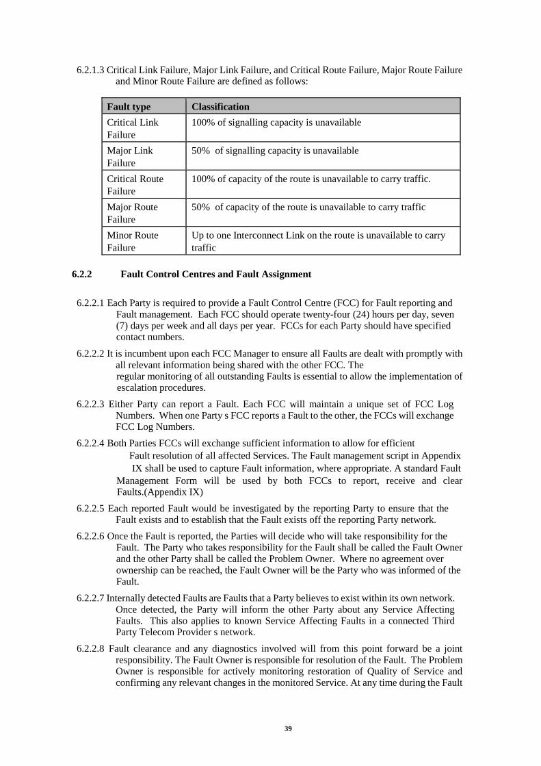
39
6.2.1.3 Critical Link Failure, Major Link Failure, and Critical Route Failure, Major Route Failure and Minor Route Failure are defined as follows:
Fault type Classification
Critical Link
Failure
100% of signalling capacity is unavailable
Major Link
Failure
50% of signalling capacity is unavailable
Critical Route
Failure
100% of capacity of the route is unavailable to carry traffic.
Major Route
Failure
50% of capacity of the route is unavailable to carry traffic
Minor Route
Failure
Up to one Interconnect Link on the route is unavailable to carry
traffic
6.2.2 Fault Control Centres and Fault Assignment
6.2.2.1 Each Party is required to provide a Fault Control Centre (FCC) for Fault reporting and Fault management. Each FCC should operate twenty-four (24) hours per day, seven (7) days per week and all days per year. FCCs for each Party should have specified contact numbers.
6.2.2.2 It is incumbent upon each FCC Manager to ensure all Faults are dealt with promptly with
all relevant information being shared with the other FCC. The regular monitoring of all outstanding Faults is essential to allow the implementation of escalation procedures.
6.2.2.3 Either Party can report a Fault. Each FCC will maintain a unique set of FCC Log Numbers. When one Party s FCC reports a Fault to the other, the FCCs will exchange FCC Log Numbers.
6.2.2.4 Both Parties FCCs will exchange sufficient information to allow for efficient
Fault resolution of all affected Services. The Fault management script in Appendix
IX shall be used to capture Fault information, where appropriate. A standard Fault
Management Form will be used by both FCCs to report, receive and clear Faults.(Appendix IX)
6.2.2.5 Each reported Fault would be investigated by the reporting Party to ensure that the Fault exists and to establish that the Fault exists off the reporting Party network.
6.2.2.6 Once the Fault is reported, the Parties will decide who will take responsibility for the Fault. The Party who takes responsibility for the Fault shall be called the Fault Owner and the other Party shall be called the Problem Owner. Where no agreement over ownership can be reached, the Fault Owner will be the Party who was informed of the Fault.
6.2.2.7 Internally detected Faults are Faults that a Party believes to exist within its own network. Once detected, the Party will inform the other Party about any Service Affecting Faults. This also applies to known Service Affecting Faults in a connected Third Party Telecom Provider s network.
6.2.2.8 Fault clearance and any diagnostics involved will from this point forward be a joint responsibility. The Fault Owner is responsible for resolution of the Fault. The Problem Owner is responsible for actively monitoring restoration of Quality of Service and confirming any relevant changes in the monitored Service. At any time during the Fault

40
resolution, if the Fault Receiving Party can demonstrate that the Fault lies within the Fault Reporting Party s network, Fault Ownership will transfer to the Fault Reporting Party.
6.2.3 Fault Resolution
6.2.3.1 The stages associated with Fault resolution are presented in Figure 6.2.
Reaction Time
Figure 6.2
6.2.3.2 If, during Fault resolution, it is established that the ownership of the Fault is in the System of the Problem Owner, then the roles will be reversed, i.e. the Fault Owner will become the Problem Owner and vice versa.
6.2.3.3 A Fault is classified as cleared when the Fault Owner informs the Problem Owner that the Fault has been rectified and the Problem Owner has verified this.
6.2.3.4 The Reaction Time (a maximum time of 60 minutes as specified in Schedule 4 (Service Level Agreements)) is the period in which:
• The Parties agree ownership of the Fault i.e. the Fault Owner and Problem Owner
are determined
• The Fault priority is determined; whether Fault is Service Affecting or Non Service Affecting. If there is no agreement, then by default the Fault is classified as Service
Affecting.
• The Fault Owner specifies expected Resolution Time.
6.2.3.5 A Fault will be deemed as Started at the end of the Reaction Time Period.
6.2.3.6 The Resolution Time is the period in which:
• Fault Owner clears the Fault
• Fault Owner informs the Problem Owner of progress and when the Fault is cleared.
6.2.3.7 A Fault will be deemed Ended when the Problem Owner informs the Fault Owner that the Fault has been cleared.
6.2.3.8 Fault Resolution Times and associated penalties are specified in Schedule 4 (Service Level Agreement) and copied below
Fault Type Time To Resolution Penalty
Service Affecting > 4 Working Hours 10% Quarterly Rental Charge
> 8 Working Hours 20% Quarterly Rental Charge
> 16 Working Hours 30% Quarterly Rental Charge
Resolution Time
Verification Time

41
> 24 Working Hours 50% Quarterly Rental Charge
> 36 Working Hours 75% Quarterly Rental Charge
> 48 Working Hours 100% Quarterly Rental Charge
Non Service Affecting < 3 Business Days No Penalty Incurred
6.2.3.9 Occasionally, Resolution Times for Service Affecting Faults reported during normal
Working Hours may extend beyond normal Working Hours. In such cases the Problem Owner agrees to provide the necessary co-operation to assist in
resolving the Fault out of normal Working Hours. For the avoidance of doubt, if a Service Affecting Fault is reported outside of normal Working Hours, best endeavours will be used to resolve the Fault, although the Resolution Time will be measured from the start of the next Working Hour.
6.2.3.10 The Verification Time (maximum time specified in Schedule 4 (Service Level Agreements)) is the period in which the Problem Owner reports its acceptance or rejection of the Fault clearance to the Fault Owner. During this period of time, the measurement of Fault Resolution Time is temporarily suspended. A Fault Clearance script is available at Appendix IX to give guidance on accepting Fault clears from the Fault Owner.
6.2.3.11 For the avoidance of doubt, if the Problem Owner does not reject or accept the clearance of the Fault by the Fault Owner within the Verification Time, the Fault shall be classified as cleared.
6.2.3.12 If both Parties cannot agree that the Fault is cleared then the Fault shall not be closed until escalation and/or investigation has been satisfactorily carried out, using appropriate mechanisms previously agreed between both Parties.
6.2.3.13 Disrupted services may be restored promptly on a temporary basis, to be followed
by permanent Fault resolution at a later date. This form of restoration shall only be used when the temporary restoration costs are considered by the Fault Owner to be reasonable.
6.2.3.14 The FCCs will manage information relating to all outstanding Faults, including status data. This information will be made available to either Party on a case by case basis at agreed intervals or as required.
6.2.3.15 Both Parties field staff may liaise directly to resolve a current Fault as deemed necessary. However, all information must be communicated to the respective FCCs to ensure the maintenance of Fault records and the taking of appropriate action.
6.2.3.16 Where it is considered necessary to pass live test traffic across the Interconnect permission to do so must first be granted by the respective FCC s. However such test traffic should be avoided at any time during the highest traffic periods
6.2.4 Re-classifications, Suspensions and Escalation
6.2.4.1 At any time during the resolution of a Fault, the Problem Owner may, with sufficient documented justification, request a change in status of the Fault from NSA to SA at which point the Resolution Time will need to be reviewed. Similarly, the Fault Owner may also request a change in status of a Fault from SA to NSA with the required documented justification.

42
6.2.4.2 If for any reason the resolution of a Fault is impeded, due to the Problem Owner, the Fault Owner may, with proper documented justification, suspend the measurement of the Fault Resolution Time.
6.2.4.3 Fault Escalation can be instigated when:
• the Problem Owner raises concerns about the speed of Fault resolution
• when the Fault Owner requires greater co-operation from the Problem Owner
• when the target Resolution Time for a Fault, as stated in Schedule 4 (Service Level Agreements) has elapsed without Fault resolution.
6.2.4.4 There are in total four levels of escalation. Escalation times for each level are shown below and are measured from the start of the Resolution Time.
Fault Status First Level Second level Third Level Fourth level
Service Affecting Immediate 4 Working Hours 8 Working Hours 1 Business Day
Non Service Affecting Immediate 1 Business Day 2 Business Days 3 Business Days
6.2.4.5 The above escalation regime can be delayed at the discretion of the FCC for 24 hours as follows
• In the event of a major external plant failure (e.g. cable dug up, major element failure, etc.), or
• For a mutually agreed period where the Fault has been identified and is being addressed by field staff of either Party.
Mandatory escalation levels Sure/Telco
Note: NSA Faults will not be escalated outside of normal Working Hours.
Escalation Telco Sure
First TBA Fault Controller
Second TBA Fault Management Supervisor
Third TBA Liaison Manager
Fourth TBA Director of Carrier Services
6.2.4.6 Initiation of the escalation process shall be done through the Parties FCCs. The FCCs will be responsible for co-ordinating the entire escalation process and maintaining the escalation records. Each level of escalation should be used before advancing to a higher stage. Escalations are to be made by the appropriate representative of the Party; e.g. if the Problem Owner requires a level 3 escalation it is expected that the Problem Owner s level 3 representative will contact the Fault Owner s FCC. The FCC will then call out their level 3 representative in order to set up direct communications
6.2.4.7 Initiation of the escalation process is done by phone, fax or other agreed media. Documented records must be kept of the entire process.
6.2.4.8 Every effort shall be made by both Parties to reach agreement at each escalation level before proceeding to the next level.
6.2.4.9 The Parties can agree on set escalation deadlines for specific circumstances.

43
6.2.5 Retail Subscriber Reported Faults
6.2.5.1 Occasions will arise when Subscribers of one Party attempt to report Faults to the
other Party; e.g. A Sure Subscriber who has a problem with his/her telephone at home reporting the problem whilst at work using a line connected to the Telco. In these circumstances the Party receiving the Call will notify the Subscriber of the contact number for the Subscriber s own operator, and will NOT log a Fault. If, however, subsequent investigation by the Subscriber s own operator indicates that the Fault is with the other Party, then the Fault will reported between FCCs using the procedures contained within this document.
6.2.6 Fault history
6.2.6.1 Both Parties will be responsible for maintaining a database that shall contain details of all Faults handled between the two FCCs. Records of all Faults are to be kept for a minimum of 12 months.
6.2.7 Point of Connection Responsibility for In Span Interconnect
6.2.7.1 This form of Interconnect is where each Party provides their own Switch and transmission equipment and the two operators Networks meet at an agreed point on the fibre optic cable. Each Party is responsible for their own equipment and the transmission media up to the PoC.
6.2.7.2 It is incumbent upon each Party to prove a Fault away from the equipment that they are responsible for, before a Fault is raised with the other Party.
6.2.8 Point of Connection Responsibility for Customer Sited Interconnect
6.2.8.1 With this form of Interconnect, one Party effectively leases capacity from the
other and is therefore responsible for the maintenance of their own Switch and any local
transmission equipment that extends the outputs of their Switch ports to the Network Termination Point (NTP) supplied by the other Party. The Party providing the capacity is responsible for their own Switch, the transmission elements at their end, the Carrier System, the cable, NTP and break out of 2MBit/s ccts at the other Party s premises.
6.2.8.2 It is incumbent upon each Party to prove a Fault away from the equipment that they are responsible for, before a Fault is raised with the other Party.
6.3 Planned And Emergency Maintenance
6.3.1.1 Planned maintenance encompasses:
• Work that affects, or has the potential to affect the Carrier System or its underlying E1Interconnect Links or their Quality of Service
• Work that affects, or has the potential to affect the Quality of Service provided to Subscriber Connections
• Work that affects, or has the potential to affect the Quality of Service provided by the other Party s System.
6.3.1.2 The Party planning to carry out planned maintenance activity (the maintenance Party) should provide at least fifteen (15) Business Days notice to the other Party, unless otherwise mutually agreed by both Parties.

44
6.3.1.3 If the other Party determines that the planned maintenance has the potential to adversely effect its Services, then it should contact the maintenance Party within five (5) Business Days of the first notice, with a view to negotiating a mutually agreed date for planned maintenance activity.
6.3.1.4 Advice of proposed planned work will be provided by facsimile, the receiving Party should acknowledge receipt of the advice by facsimile within one working day and provide a reference number to the originating Party.
6.3.1.5 Both Parties must be in possession of the final schedule at least three (3) Business Days before the commencement of planned maintenance. If an agreement cannot be reached within this time frame, then the escalation procedure as described in Section 6.2.4 should be applied, with any necessary modifications.
6.3.1.6 Emergency maintenance is a type of maintenance work that needs to be carried
out immediately due to the impact or potential impact to services. If this work affects, or has the potential to affect the other Party s Services, then, as much advance notice will be given as the situation permits.
6.3.1.7 Subject to reaching an agreement the works will be carried out as soon as possible. Upon completion of the work the Parties should exchange confirmation that the work has been completed to the satisfaction of both Parties.
6.3.1.8 Use should be made of the Planned Works Notification form as indicated in Appendix XI.
6.3.2 System Alteration
6.3.2.1 If either Party have a need to make a System alteration at least 6 months notice must be given to the other Party specifying full technical details of the required alteration.
6.3.2.2 The receiving Party will notify the other Party of any changes necessary to its System to accommodate the alteration within one month and supply a quotation for the work if the normal practice of both Parties meeting their own costs is considered not appropriate. However each Party will normally pay its own costs if the alteration is to mutual benefit.
6.3.2.3 The Parties will discuss and agree a timetable for the work within 3 months. Should agreement not be reached escalation should take place in line with the dispute process.
6.3.2.4 Should any material changes be made to the System the Technical Manual should be updated to reflect the changes in network design etc.
6.4 Miscellaneous O&M Provisions
6.4.1 Procedure for Data Management Amendments
6.4.1.1 Each Party will order alterations to number ranges (or numbers) and Carrier Select
Routing Prefixes to and from which Calls are to be conveyed pursuant to the
Schedule 3 (Service Descriptions) and Section 4.6 of this Operations & Maintenance Manual. Notwithstanding Clause 34 of the Agreement the date on which such notification is deemed to be received will be the date of receipt.
6.4.1.2 Within three (3) Business Days of date of an accepted DMA Order, the Service Taker will notify all operators adopting the UK National Numbering Scheme of the alterations to such number ranges as appropriate.
6.4.1.3 Each Party will perform the necessary alterations to its respective Systems to facilitate the alteration to the number ranges and Carrier Select Routing Prefixes within twenty

45
(20) Business Days of date of receipt and will inform the other Party of completion of the necessary alterations within one (1) Business Day of completing the necessary alterations.
6.4.1.4 The Service Taker will perform any necessary tests to verify the use of the codes, however the Parties will co-operate in order to conduct any necessary joint testing, where agreed applicable, and will use all reasonable endeavours to complete such testing within one (1) Business Day of alteration.
6.4.2 Process for New Services
6.4.2.1 The following process shall apply when a Telco submits a request for a new Service in line with Clause 4 of the Agreement.
6.4.2.2 This process should not be confused with the provision of existing and agreed
Services in line with Schedule 4 (Service Level Agreements) and Section 4.5 of this Operations & Maintenance Manual. See Figure 6.2 below for an overall process flow chart.
6.4.2.3 The Telco may request and Sure must seek to agree to provide any requested Service which it already provides to other Parties or to its own retail arm. The requesting Party must supply a statement of requirements indicating fully the requirements of the requested Service.
6.4.2.4 Sure must confirm within 30 calendar days of receipt of the statement of requirements that it suitably identifies the requirements of the new Service.
6.4.2.5 If the Service Supplier accepts a request for a new Service, both Parties shall endeavour to agree the technical and commercial aspects of Interconnection within 75 calendar days after receipt of the statement of requirements unless otherwise agreed by the Parties.
6.4.2.6 If the Service Supplier rejects a request for a new Service a dispute may be deemed to have arisen between the Parties and the Parties shall in the first instance be referred to the Parties’ respective Liaison Managers for resolution. In the event that the Liaison
Managers shall fail to resolve such dispute. Any disputes will be resolved in accordance with Clause 35 of the Agreement.
If the Service Supplier is obliged to publish a Reference Offer and the request is for a new Interconnect service, the agreed technical, operational and commercial terms will be incorporated into a revision to this Reference Offer.

46
Figure 6.2 New Service Provision Process
6.4.3 Procedure for Directory Number Inclusion Service
6.4.3.1 Appendix X details the format of directory information required for the directory number inclusion service. The Service Supplier will require the Service Taker to provide information relating to their Retail Subscribers to be sent by email or fax, in the standard format set out in Appendix X.
6.4.4 Fraud Control
6.4.4.1 Staff of both Parties should advise their respective Liaison Managers should they become aware of or suspect any fraudulent activity.
6.4.5 Confidentiality
6.4.5.1 Staff of both Parties should keep in confidence any information they may become aware of regarding the other Party s Subscribers or System whilst performing their normal duties.
6.4.5.2 Any doubt or query regarding the disclosure of confidential information should be referred to the respective Liaison Managers.
6.5 Operational Requirements
6.5.1 C7 Build control
Service Taker Requests New Service. Provides a
Detailed Statement of Requirements
Service Supplier Acknowledges Receipt
In < 5 Days
No
Yes
Service Supplier Accepts Obligation?
In < 60 Days*
Statement of Requirements
Adequate & Concise? In <30 Days*
Discuss & Agree Technical & Commercial Terms
In <75 Days*
Escalation Process Clause 35 of Agreement
No
Yes
* All Days Commence From Acknowledgement

47
6.5.1.1 This Section details the procedure for the assessment and notification of proposed changes to switching system build levels with regard to C7 signalling. Where interworking is affected the other Party will be notified in order that a view may be taken regarding the need for further testing. It may also be appropriate to give consideration to the effect the change may have on Telcos that are not directly Interconnected.
6.5.1.2 Generally the following three categories are to be notified:
• Major revision to C7 - Planned
• Minor software or hardware revision to C7 - Planned
• Emergency revision to C7
6.5.1.3 Changes must be notified using the procedure indicated below, but for changes due to an emergency revision it may not be possible to provide advance notice. However, the
notification process for such emergency changes must still be followed in retrospect, at the earliest opportunity, in order to formally notify and obtain agreement to changes put in place and also to record and allow the changes to continue in existence.
6.5.1.4 A minimum of 15 working days notice of any change is required prior to its introduction. Agreement should be reached within the 15 day period. However a maximum notice period of 3 months is recommended where testing and analysis of results may prove necessary. The notice period commences upon receipt of the form of notification.
6.5.1.5 Each Interconnecting Telco will nominate an officer responsible for Data Build
Upgrades. These officers will be responsible for completing the form shown at Appendix XII. Part 1 will be completed by the originator and forwarded to the other Party for acknowledgement of receipt and as a trigger to discuss any possible inter
network testing. The originator will complete Part 3 when implementation of the changes has been carried out to the satisfaction of both parties. Transfer of the form will be by Fax or EMAIL.
6.5.2 SDH Network Element Software Control
6.5.2.1 This Section details the procedure for the assessment and notification of proposed changes to SDH Network Element hardware, software and features where used on In Span Interconnects.
6.5.2.2 Where interworking is affected, the Party proposing the changes will notify the other Party in order that a view may be taken regarding the need for further interworking testing.
6.5.2.3 At least 3 months notice is required to reach agreement to any changes prior to their introduction.
6.5.2.4 Each Interconnecting Party will nominate an officer responsible for SDH Network Element upgrades. These officers will be responsible for action within their own company and for advising the other Party.
6.5.2.5 The up-grading Party will complete the form shown at Appendix XIII. Part 1 will be completed by the originator and forwarded to the other Party for acknowledgement of receipt and as a trigger to discuss any possible inter working testing. The originator
will complete Part 3 when implementation and testing of the changes have been carried out to the satisfaction of both parties.
6.5.2.6 Transfer of the form will be by Fax or EMAIL
6.5.2.7 Upon receipt of a change request the Party must consider the implications of the nominated changes and should determine and agree what interworking tests will be required with the originator.

48
6.5.2.8 Advice of such testing requirements must be made to the originator giving suitable notice period to allow the appropriate tests to be performed within the 3 month validity period of the change request.
6.5.3 Traffic Management
6.5.3.1 Traffic Management is the real time control of traffic flows in order to maximise the effective use of the available capacity, and to maintain the customers Quality of Service over the Interconnect.
6.5.3.2 In addition to the Fault management processes that deal primarily with the restoration of service through the rectification of element failures Traffic Management processes can either restore traffic in advance of the element restoration or protect the Interconnect from further degradation.
6.5.3.3 Access to either Parties traffic management staff will be via the respective FCCs.
6.5.3.4 Traffic Management Responsibilities:
• If either Party is aware of any circumstance that may give rise to an abnormal
increase in traffic over the Interconnect they will advise the other Party and agree the application of any controls. Use should be made of the forms attached at Appendices XIV and XV.
• If either Party becomes aware of a problem in their network that may affect the traffic over the Interconnect they are to inform the other Party. Where Call gapping on a route is required the form at Appendix XV should be used to request the level of gapping required.
• Where it is necessary to reduce the volume of traffic offered to an Interconnect route
a request may be made to the other Party for controls to be applied. The duration of the control and the degree of selectivity will be agreed between the two Parties traffic management staff.
• If either Party believes that the traffic management controls applied by the other Party are acting to the detriment of traffic flow then they shall liaise and discuss the application of the controls with the other Party with a view to making alternative
arrangements.
6.5.4 Planned Media Events
6.5.4.1 Occasionally, media events e.g. phone-ins. are pre-planned by Subscribers of Sure or other Telco networks. (The networks may be directly or indirectly connected to each other) These planned media events generate a larger than normal volume of calls into
networks. These events can occur during the normal working day or during times generally classed as periods of low traffic .
6.5.4.2 To prepare for such planned media events, both Sure and all Telcos should endeavour to provide each other with all relevant information a minimum of 3 working days prior to the commencement of the event.
6.5.4.3 Both Parties must provide the other with the full list of all numbers used for such events that are connected to their network, e.g. pledging centres, event reception numbers etc. Any other special routing requirements relating to the event must also be identified.
6.5.4.4 By such exchange of information both operators may have advance information so that any necessary traffic management actions and controls can be put in place at the time of the event.

49
6.5.4.5 The forms in Appendices XIV and XV are to be used to advise the details of phone-ins and to notify the other Party of the event and, if required, requesting any Call gapping.
6.5.5 Maintenance of Interconnect Records
Both Parties shall keep accurate records of the Interconnect. These records shall include
where applicable:
• Designated point of Interconnect.
• Interconnect end locations and physical route.
• Contact points and phone numbers.
• Limits and areas of responsibility for each operator.
• Performance standards required of the Interconnect.
• The date the Interconnect route was bought into maintenance.
• The date the Interconnect route is to be or was brought into service.
• Equipment and cable details.
• Carrier System circuit identity, quantity, Order and in-service dates. • 2Mbit/s circuit identity, quantity, Order and in-service dates
• Fault history on a per circuit basis.
6.5.5.1 These records are to be stored such that they are available to each Parties personnel who require access to them. From time to time the records should be audited to ensure that the records remain a true reflection of the Interconnect Capacity and that it is possible to reconcile the volumes of provision and charges levied between the Parties.
6.5.6 112 and 999 Test Calls
6.5.6.1 There is a requirement to make test calls to the Sure Emergency Call Handling Service. These test calls should be made on a regular basis, in agreement with the manager of operator services
6.5.7 Alarm Handling
6.5.7.1 Any staff identifying Faults on Interconnect Links shall inform their own FCC. The FCC will work on the Fault using their own internal procedures until such time that the assistance of the other Party is required.
6.5.7.2 Where the FCC see, or are informed of, "distant" alarms coming from the other operator, the FCC are to gain positive confirmation that the other Operator has seen the alarm and is working on the situation, and are NOT to assume that the alarm is being worked on.
6.6 Call Tracing Procedures
6.6.1 Types of Call Trace
6.6.1.1 The instances necessitating Call traces are classified as Emergency or Engineering. These are typically:
a) Emergency Call Traces

50
• Emergency (An emergency of any kind, including any circumstance whatsoever resulting from major accidents, natural disasters and incidents involving toxic or radioactive materials).
• Malicious calls
• Fraud
• Police and Security
• Serious Crime
b) Engineering Call Trace
• Test Calls
• Customer or Operator held Faults.
6.6.1.2 The only points of interface to request or handle a Call trace over the PoC will be each Party s FCC. Both Parties will use their best endeavours to hold and trace calls at the time the Call is in progress. On some occasions this may not be possible, in which case each Party will endeavour to perform a trace retrospectively using Call detail records to achieve this. Each Party will be separately responsible for ensuring their own compliance with statutory and licence obligations.
6.6.2 Emergency Call Trace
6.6.2.1 Emergency Call traces within either network that terminate on an Interconnect route should be passed to the respective FCC. The FCCs will liaise to effect a Call trace within their own networks.
6.6.2.2 All such requests will be traced through either network without delay. The critical
information to be passed by the requesting FCC is the channel identity. On successful completion the Subscriber information, telephone number, name and address, if derived, will be transferred between the FCCs without recourse to either company s corporate security personnel. When a Call is traced to another Interconnect route the channel identity will be returned.
6.6.3 Engineering Call Trace
6.6.3.1 Engineering Call traces may be requested but no priority will be given by either Party. These calls will be traced only at the discretion of the FCC. Only the telephone number can be transferred within this type of trace and again only at the discretion of the FCC concerned.
6.6.3.2 Call hold and trace will be carried out solely under the control of the FCCs and each Party will have its own internal guidelines for dealing with Call hold and trace and permission for engineers to carry out this activity will be given by the points of contact.

51
7 SAFETY
7.1 General
7.1.1.1 It is the responsibility of each individual, under the terms of the Health and Safety at Work (General) (Guernsey) Ordinance 1987, to ensure the safety of their working environment and to work in a safe manner. The building owners shall be prepared to accept questions and comments regarding safety from visiting working parties and to take appropriate action. Also, visitors shall accept directions regarding safety and safe working practices from the building owner s representative. Should any dispute arise
about a practice being safe, work should cease and the matter escalated immediately by the representatives of each Party to their Liaison Manager for management decision.
7.1.1.2 Both Parties should ensure that they meet the safety provisions of the Agreement, the Technical Manual and this Operations & Maintenance Manual and ensuring that
• Operations do not endanger the health and safety of staff, contractors or Subscribers of their own or the other Party
• Damage or impairment is not caused to the other Party s System
• No interference occurs to Services provided by the other Party except in the protection of its own System in line with the Technical Manual and Operations & Maintenance Manual.
7.2 First Aid
7.2.1.1 Should a member or visitor of either Party s staff become ill or sustain an injury whilst attending any site every priority must be offered to assist the individual in the receipt of first aid. An individual trained in first aid must administer such aid, where appropriate and in the correct manner.
7.3 Accident Reporting
7.3.1.1 Should any visitor or employee at any site have an accident full details must be reported to both Parties in accordance with internal standing instructions.
7.4 Site Safety
7.4.1
Staff working on equipment at either Party s premises must be fully trained in
the installation operation and maintenance of that equipment. All safety
procedures must be followed.
7.4.2 Optical Safety
7.4.2.1 Due to the dangers of exposure to radiation from optical power sources it is imperative that safety procedures be followed which ensures that personnel do not work on fibre
optical systems unless the power source to the laser has been turned off at both terminals.
7.4.3 Duct Seals

52
7.4.3.1 It is the responsibility of the building owner to carry out regular routine checks to confirm the effectiveness of the building duct seals and of any water or gas detection equipment. Such checks would be performed in line with the building owners own operating procedures.
7.4.4 Electrostatic Protection
7.4.4.1 All link equipment must comply with ITU-T K.43 for network equipment Electromagnetic Compatibility (EMC) requirements and must comply with any national regulations relating to electromagnetic and electrostatic compatibility.
7.4.4.2 All link equipment must comply with ITU-T K.42 for immunity to radiated electromagnetic energy.
7.4.4.3 All link equipment must comply with ITU-T K.32 for electrostatic discharge
7.4.4.4 The link equipment must be immune to radiated electromagnetic field of up to 3V/m.
7.4.4.5 All link equipment must comply with any other EU directive and/or national regulations relating to electromagnetic and electrostatic compatibility, whichever is the most stringent.
7.4.4.6 All staff working on or near equipment must be made aware that electrostatic potential generated during movement and handling of certain circuit cards can cause transmission errors and damage to equipment if precautions are not taken.
7.4.4.7 Unless Special Handling Areas are available the following principles apply:
• Always treat the System as static-sensitive.
• Replace equipment covers as soon as possible.
• Wear, if possible, natural fibre or anti-static treated outer clothing and footwear.
• Ensure that, equipment carrying boxes and cases are connected to earth before they are opened.
• Always wear a skin-contact wrist strap, which is connected to one of the earth studs provided, when working on circuit cards and System racks.
• If floors and working surfaces are not marked as being of conductive or partially conductive material, put down electrostatic control mats in the working area and connect them to earth studs.
7.4.5 Control of Substances Hazardous to Health (COSHH)
7.4.5.1 Any substances brought onto the premises of either Party must have been assessed and appropriate control measures adopted.
7.4.6 Electrical Safety
7.4.6.1 All equipment must be designed, installed, tested and maintained to meet the requirements of the appropriate electricity at work regulations.
7.4.7 Fire Control
7.4.7.1 Fire control must be strictly managed and defined in corporate documentation.

53
8 Appendices
8.1 Listing
Number Section Appendix Title
APPENDIX I 8.1.1 Relationship Management Contact List
APPENDIX II 8.1.2 Monthly Performance
APPENDIX III 8.1.3 Interconnect Traffic Forecast
APPENDIX IV 8.1.4 Interconnect Capacity Forecast
APPENDIX V 8.1.5 Ordering Interconnect Capacity on existing PoC
APPENDIX VI 8.1.6 Ordering Interconnect Capacity on new Carrier System or
new PoC
APPENDIX VII 8.1.7 Initial Ordering of Services
APPENDIX VIII 8.1.8 Data Management Orders
APPENDIX IX 8.1.9 Fault Management Forms
APPENDIX X 8.1.10 Directory Number Inclusion
APPENDIX XI 8.1.11 Planned Maintenance
APPENDIX XII 8.1.12 C7 Change Advice
APPENDIX
XIII
8.1.13 SDH Element Change Advice
APPENDIX XIV 8.1.14 Phone in Notification Form
APPENDIX XV 8.1.15 Request for Call/Route Gapping
APPENDIX XVI 8.1.16 Interconnect pro forma

54
8.1.1 Appendix I. Relationship Management Contact List
Name Address Telephone Email Address
Liaison Manager (Head of
Carrier Services)
Steve Ozanne Sure, PO Box 3, Guernsey.
01481 700700 Extn 7561
Planning Manager
(Access Network) Ian McColl Sure, PO Box
3, Guernsey. 01481 700700 Extn 7302
Operations Manager Switching
(Senior Engineer
Core Network)
Kieron Le
Huray
Sure, PO Box 3, Guernsey.
01481 700700 Extn 7318
Operations Manager Transmission
(Senior Engineer
Core Network)
Kieron Le
Huray Sure, PO Box 3, Guernsey.
01481 700700 Extn 7318
Fault Control Manager (NOC
Manager)
Tony Lanoe Sure, PO Box 3, Guernsey.
01481 700700 Extn 7321
Billing Manager
Dave Moorat Sure, PO Box 3, Guernsey.
01481 700700 Extn 7541
Service Quality Manager
TBA Sure, PO Box 3, Guernsey.
01481 700700
Project Manager
TBA Sure, PO Box 3, Guernsey.
01481 700700
This contact list has been submitted as part of the Reference Offer framework outlining the roles and
responsibilities for relationship management
Service Taker Service Supplier
Signature Signature
Name Name
Position Position
Date Date
8.1.2 Appendix II. Monthly Performance
INSTRUCTIONS:
The Service Taker will indicate in Section I, all existing and ordered services. In each month following the report period, both Parties will exchange the information in Sections II and III for each service.

55
SECTION I — EXISTING & ORDERED SERVICES

56
SECTION III — INTERCONNECT RESOLUTION LOG

57
8.1.3 Appendix III Interconnect Traffic Forecast
The Service Taker shall complete both Sections of the Interconnect Traffic Forecast.
SECTION I — QUARTERLY FORECASTS
Service Taker to complete a separate Forecast for each of the Quarters in the first year including all shaded areas.
Forecast Quarter
Start Date End Date
Service
ref.
Origin Destination SERVICE TRAFFIC FORECAST
Total traffic
(Erlangs/mins)
Busy Hour
period
Busy Hour
traffic
(Erlangs/mins)
This Forecast has been submitted as part of the reference offer responsibilities for forecasting
Service Taker Service Supplier
Signature Signature
Name Name
Position Position
Date Date
SECTION II — YEARLY FORECAST
Service Taker to complete a cumulative total Forecast for the second year including all shaded areas.

58
Forecast Year
Start Date End Date
Service
ref.
Origin Destination SERVICE TRAFFIC FORECAST
Total traffic
(Erlangs/mins)
Busy Hour
period
Busy Hour
traffic
(Erlangs/mins)
This Forecast has been submitted as part of the reference offer responsibilities for forecasting
Service Taker Service Supplier
Signature Signature
Name Name
Position Position
Date Date
8.1.4 Appendix IV — Interconnect Capacity Forecast
The Service Taker shall complete Section I of this Forecast and also Section II, where applicable.
SECTION I — FORECASTS FOR EXISTING POINTS OF INTERCONNECT
Service Taker to complete all shaded areas for the forecasting of Interconnect Capacity for an existing point of Interconnection.

59
SECTION II — FORECASTS FOR NEW POINTS OF INTERCONNECT
Service Taker to complete all shaded areas for the forecasting of Interconnect Capacity for a new point of Interconnection. If a new point of Interconnection is not forecasted, this form shall remain unpopulated.

60
8.1.5 Appendix V — Ordering Interconnect Capacity on Existing PoC
The Service Taker shall complete this Order Form when ordering additional Interconnect Links in conjunction with an Optical Network Interconnect Service, where a Carrier System already exists and can support the augmentation of the Ordered Interconnect Capacity.
Service Taker Order Date Ready for Service
Date
Existing Interconnect Links
Service ref Origin/
Destination
Carrier
type
No of
Links
Trunk
Route
name
I/C or O/G No.
This Order has been submitted as part of the reference offer responsibilities for Ordering
Service Taker Service Supplier

61
Signature Signature
Name Name
Position Position
Date Date

62
8.1.6 Appendix VI — Ordering Capacity on new Carrier System or new PoC
New requirements Order
Interconnect Switches
Service
Taker
Point code
(Decimal)
Service
Supplier
Link requirements
Origin Destination Trunk route name Tru rout I/C O/G
Link requirements continued (Row 1 in Link Requirements Table above relates to Row 1 the
Signalling Link Allocation
Time slot
info CIC assignment
This Order has been submitted as part of the reference offer responsibilities for Ordering
Service Taker
Signature

63
The Service Taker shall complete this Order Form when ordering Interconnect Links in conjunction with an Optical Network Interconnect Service, where a new Carrier System is required to support the Ordered Interconnect Capacity.
8.1.7 Appendix VII — Initial Ordering for Services (IS Order Form)
The Service Taker shall complete this Order Form when placing Initial Orders for Services and shall complete any other necessary Order forms (such as DMA Orders) as part of the Order for Initial Service.
Service Taker
Service Supplier
Service Service Reference Service Ordered
Sure On-Island Termination 3.01
Sure On-Island Origination (inc. 100) 3.02
Sure On-Island Origination (exc. 100) 3.02
Sure On-Island Transit 3.03
Sure Off-Island Transit 3.04
Sure On-Island FreePhone Origination 3.05
Sure On-Island LocalCall Origination 3.06
Emergency Services 3.07
Directory Number Inclusion 3.08
Data Management Amendment 3.21
In Span Interconnect (ISI) 3.22
Customer Sited Interconnect (CSI) 3.23
Name
Position
Date

64
This Order has been submitted as part of the reference offer Section for Ordering
Service Taker Service Supplier
Signature Signature
Name Name
Position Position
Date Date
8.1.8 Appendix VIII — Data Management Amendment Orders
The Service Taker shall complete all shaded areas of this Order Form when ordering Data Management Amendments in conjunction with Number Ranges, Carrier Selection Routing Prefixes (CS Routing Prefixes) and Initial Orders for Services.
Service Taker Date
Data Amendment
Service
ref.
Amend/
New/
Cease
Trunk Route Name
Ready for
test date
Implementation
date Req d
Test
Req d
(Y/N)
Test No.
Data Information
The Service Taker shall provide specific detailed information on the specific Data Amendment being
ordered to enable the Service Supplier to provide the appropriate Service.
This Order has been submitted as part of the reference offer responsibilities for Ordering
Service Taker Service Supplier

65
Signature Signature
Name Name
Position Position
Date Date
8.1.9 Appendix IX. Fault Management Form
Both Parties shall maintain a log of the information relating to all reported Faults. This information shall be made available to either Party at agreed intervals or as required.
SECTION I - FAULT REPORT SECTION II - FAULT CLASSIFICATION
ITEMS DETAILS
Sure Fault log no.
Telco Fault Log #
Fault report date
Time Reported
Person Reporting
Fault Owner
Problem Owner
ITEMS DETAILS
Fault Type
(Network / Link)
Fault status (SA/NSA)
Critical/Major/Minor Link/Route
Service Affected
Supplementary details to aid Fault
identification
SECTION III — FAULT RESOLUTION
ITEMS DETAILS
Cause of Fault
Fault Owner Person Clearing
Fault Owner Person Clearing date + time
Problem Owner Person receiving clearance

66
Problem Owner Person receiving clearance date + time
Problem Owner Person accepting Fault closure
Problem Owner Person accepting Fault closure date & time
Reaction time
Resolution time
Verification time
SECTION IV — FAULT RESOLUTION ACTIVITIES
DATE TIME ACTION TAKEN
Contd .\
Fault type Classification
Critical Link Failure 100% of total signalling capacity is unavailable
Major Link Failure 50% of total signalling capacity is unavailable
Critical Route Failure 100% of total capacity of the route is unavailable to carry traffic.
Major Route Failure 50% of total capacity of the route is unavailable to carry traffic
Minor Route Failure Up to one Network Link on the Route is unavailable to carry traffic
SECTION V — FAULT ESCALATION (if appropriate)
Dispute details

67
Sure escalation list
Date Name Position Response
Telco escalation list
Date Name Position Response
SECTION VI — INTERCONNECT LINK FAULT REPORTING SCRIPT (As
Appropriate)
The Problem Owner shall consider the following criteria when reporting any 2Mbit/s Interconnect Link Faults.
1 Exact designation(s) of faulty circuit(s).
2 Company Name.
3 Name of person reporting the Fault.
4 Contact details for person reporting the Fault.

68
5 Contact details for person responsible for diagnostics
and restoration.
6 Outside Normal Hours: Contact details for responsible person to assist the Fault Owner. Required for Service Affected Fault.
7 Has the faulty circuit(s) ever been brought into
service? (A check should first be made to
conclusively prove the circuit has been
commissioned and tested okay).
To Continue with the Fault
Report, the answer here
should be YES.
8 Has the Fault been proved off Reporting Party
network?
To Continue with the Fault
Report, the answer here
should be YES.
9 When was the Fault first raised? Date: Time:
10 Please list all relevant fault symptoms, where applicable.
Other **
Alarm Indicator Signal
Bit Error Rate
Digital Line Fail
Distant Alarm
Loss of Frame-Alignment
Loss of Multi-Frame
Alignment
Power Failure
Remote Manual Blocked
RMB*
Slip
11 Do you have other relevant information?
* If an RMB Fault, please supply channels affected.
** If Other, please supply description of alarm
conditions.
12 Does the faulty circuit(s) support C7 signalling? YES / NO
13 Has the agreed level of service been adversely affected
as a result of this Fault, or is it likely to be in the next 24
hours?
YES / NO
14
Will co-operation be made available to assist Fault Owner in diagnose and rectify the Fault outside of normal Working Hours? (If answer is No, then the Fault Owner may be obliged to re-classify the Fault : Non-Service Affecting).
YES / NO
15
Service Affecting Fault - the answers to both Q13 & Q14
must be Yes.
16
If answers to either Q13 or Q14 are NO and
Service Affecting Fault is required, then please supply
valid reasoning for escalation.
17 What is the Fault reference your company has
allocated?

69
18 Network Fault Detail:
Circuit Reference: (To identify at least the PoC)
Destination Number, or range of numbers being
dialled.
Description of Fault details: calls failing to one
destination number, one area code, to NU, no tones,
EET.... etc.
Has any traffic management actions been taken, e.g.
Call gapping applied to the route, traffic re-routed via
another carrier.
Are there any other details that may help in the localising
and rectifying of this Fault?
Has the reporting Party reproduced the Fault?
Is the problem time specific, or day specific?
Originating Subscriber(s) number(s)
SECTION VII — INTERCONNECT LINK FAULT CLOSING SCRIPT (As
Appropriate)
When Closing Fault Back to a Problem Owner
1 Is any internal Fault analysis code and the reported clearance correct for the type of Fault
reported?
2 Are all internal reporting codes recorded correctly?
3 Is the Fault description completed? Do the details of the clearance make sense when
compared with the reported Fault?
4 Do all the details of date and time of Fault clearance and any intermediate start and stop
times etc tie up with the diary entries?
5 Are the Fault duration minutes assigned to the correct Party (Sure, Subscriber, Telco).
6 Go over the whole Fault details to ensure that the clear details and diary entries add up.
Only pass the Fault back if YOU are satisfied with the quality of the information
provided. If not satisfied inform the Problem Owner that the Fault has been cleared,
but inform them that further details of the clear are being sought. The Fault should then
be escalated in order to provide the Problem Owner with a quality clear.
7 The Problem Owner should ensure that the recipient’s name and contact number details
are taken in full.
When Receiving a Clear from a Fault Owner
1 Take the name and contact number for the person clearing the Fault

70
2 Check that the clearance details tie in with the reported Fault details. If not seek
clarification of what the other Fault Owner found and what was done to clear the Fault.
3 Are the details sufficient to pass on a quality clear to a customer? If not seek further
clarification from the Fault Owner.
4 If further details are not forth coming the Fault may be escalated in order to provide a
quality clear.
8.1.10 Appendix X. Directory Number Inclusion
Entries Standards Comment
One page per Subscriber Information record Information may be provided to Sure by email or fax Format should be in accordance with relevant requirements Independent Core Database Data Definition as identified in BTDS Schedule 11, Appendix 11.1 Minimum
Name First name, last name
Installation
address (partial, or full including postcode) Note: if insufficient address
information is provided DQ searches are likely to fail e.g. J Le Page in Guernsey is
insufficient
Indication whether number is ex-directory
or not
Clear indication must be given for ex-directory
entries
Telephone
number
Indication whether number is business or consumer
Line use
Minimum mandatory data fields required for Operator Subscriber Information records are:
Surname / Trading Name
Line Use
Building Name / No.
Thoroughfare
Post Code
Telephone Number

71
8.1.11 Appendix XI - Planned Works Notification Form
PLANNED WORKS NOTIFICATION
SURE/TELCO REF. NO.
PLANNED WORK DETAIL:
TIME:
DATE:
DURATION:
REASON:
CIRCUIT(S) FROM/TO
If further information is required please contact the Fault Control Centre between 0830 and 1700
Monday to Friday on:
If complications occur during or after the scheduled work, please contact the Fault Control Centre
on:
Please email acknowledgement of receipt of this form within 24 hours.
Your Reference: Signed:
Date: Printed Name:

72
8.1.12 Appendix XII - C7 Change Advice
CCITT No. 7 Change Advice (Page 1)
Issuing Party: SURE /TELCO
Part 1
Part 2
Part 3
To be completed for any anticipated C7 change in System where there is an actual or
potential effect on interworking. Full details should be sent at least 3 months prior to the
date to be applied.
FOR ATTENTION OF: DATE:
SWITCHING UNIT TYPE:
LOCATION(S): DATE TO BE APPLIED:
OFFICER RESPONSIBLE/DEPT/TEL:
CURRENT BUILD LEVEL:
PROPOSED NEW BUILD LEVEL:
CCITT 7 INTERCONNECTS:
(List all known Switch system types Interconnected).
C7 CHANGE: (Major Revision, minor revision, Emergency)
Describe the type of C7 change on Page 2
LIKELY EFFECTS ON INTERWORKING
COMPLETED BY: NAME: .....................Sure / Telco DATE:.........
ACKNOWLEDGED RECEIPT BY
SIGNED:................................... WORK REF:............. Sure/Telco
NAME:..................................... DATE:...........................................
CONFIRMATION OF IMPLEMENTATION IN THE NETWORK
NAME:....................................
DATE:.................

73
CCITT No. 7 Change Advice - Details of Change (Page 2)
Changes to C7 hardware (Y/N) .............
S/W Changes (i.e. fixes/corrections) (Y/N) .............
Data Changes (i.e. T/Os tones etc.) Y/N) .............
Recompile of S/W (Y/N) .............
Changes to C7 Protocol (Y/N) .............
Changes to message formats and contents (Y/N) .............
Any other changes that could affect C7 Interworking (Y/N) .............
Brief Details of any Interworking Problems Fixed in Build
Detail of Changes to Message Formats/Protocols
Detail of Likely Effects on Interworking
Tests Run to Validate the Changes
Problem Specific tests from BTNR 954 (or Equivalent) (Y/N) .............
Any Tests other than BTNR 954 (Y/N) .............
BTNR 954 Test Run to Check New Message Formats
Results and Analysis of All tests Run on New Build
Completed by: Date:

74
8.1.13 Appendix XIII - SDH Network Element Change Advice
SDH Network Element Change Advice (Page 1)
ISSUING PARTY *SURE/TELCO
*Delete as appropriate
Part 1
Part 2
Part 3
To be completed for any anticipated SDH Network Element change in hardware, software
or features where there is an actual or potential effect on interworking. Full details should
be sent at least 3 months prior to the date of application of the upgrade.
FOR ATTENTION OF: *Sure /Telco DATE:
SDH NETWORK ELEMENT TYPE:
LOCATION(S): DATE TO BE APPLIED:
OFFICER RESPONSIBLE/DEPT/TEL:
CURRENT H/W, S/W LEVEL:
PROPOSED NEW LEVEL:
ISI INTERCONNECTS AFFECTED:
NETWORK ELEMENT CHANGE: (Major Revision, minor revision, Feature)
Describe the type of change on Page 2
LIKELY EFFECTS ON INTERWORKING
COMPLETED BY: NAME: ...............................................*Sure /Telco
DATE:.......................
ACKNOWLEDGED RECEIPT BY Sure/Telco
SIGNED:..................................................... WORK REF:.............................................
NAME:........................................................ DATE:......................................
CONFIRMATION OF IMPLEMENTATION IN THE NETWORK
NAME:......................................... *Sure/Telco DATE:.................................

75
Details of SDH Network Element Change (Page 2)
Changes to Element hardware (Y/N) ...................................
S/W Changes (i.e. fixes/corrections/upgrade) (Y/N) ...................................
Recompile of S/W (Y/N) ...................................
Changes to Network Element Features (Y/N) ...................................
Changes to message formats and contents (Y/N) ...................................
Any other changes that could affect SDH Interworking
Brief Details of any Interworking Problems Fixed in Build
Detail of Changes to Transmission Signals/ Formats/Protocols
Detail of Likely Effects on Interworking
Details of Proposed Interworking Tests to Validate the Changes
(Attach any supporting documentation) Results and
Analysis of All tests Run on New Build
Completed by: Date:

76
8.1.14 Appendix XIV - Phone in Notification Form
Ref. No: Phone Ins
Sure /Telco:
Number of lines:
Number(s) to be used:
Likely holding time:
How is number presented:
(e.g. TV, Radio)
Date and time of event:
Is event repeated:
Catchment area:
Contact name and number of service provider:
To be completed by Receiving Operator:
Date and time of notification:
Engineers name:

77
8.1.15 Appendix XV — Request for Call/Route Gapping
REQUEST FOR APPLICATION OF CALL GAPPING
TO: FROM:
TEL: FAX:
REF:
Please apply Call gapping at: Details of location etc
DATE: START TIME: END TIME:
NAME: SIGNATURE:
-----------------------------------------------------------------------------------------------------
TO FROM:
TEL: FAX:
REF:
The request for Call gapping has been applied at: Details of location etc
DATE: TIME:
NAME: SIGNATURE:
---------------------------------------------------------------------------------------------------------
TO: FROM:
TEL: FAX:
REF:
Please remove the Call gapping at: Details of location etc
DATE TIME:
NAME: SIGNATURE:
---------------------------------------------------------------------------------------------------------
TO: FROM:
TEL: FAX:
REF:
Call gapping has been removed at: Details of location etc
DATE TIME:
NAME: SIGNATURE:

78
8.1.16 Appendix XVI Interconnect Pro Forma
Telco Company Address:
Post Code
Switch Type Installed/Proposed?
Switch Build Level?
Hardware:
Software:
C7 Build Level:
(e.g. BTNR167 issue1/2/3, IUP issue 1/2/3, Switch C7 Feature Number)
Telco Switch Site Address
Post Code
Switch Point Code
Expected Sure Interconnect Ready for Service Date?
Details Of Any Waiver With Other Operators. YES/NO
See Attached Sheet
This Requirement: New Interconnect YES/NO
New Service YES/NO
Change to Existing Service YES/NO
CAPACITY REQUIREMENTS *
Ingress to Sure Ingress to Telco
2Mbit/s Erlangs 2Mbit/s Erlangs
Day 1 Capacity Requirement
0-6 Months Capacity Requirement
6-12 Months Capacity Requirement
1-2 Years Capacity Requirement
*To be considered as a guide. The formal requirement should be included in the forecasting process. New Market Entrant initial capacity should meet the Telco requirements for first 15months
REQUIRED Sure Services
Reference Schedule 3 Service Title Required? Yes/No
3.01 Sure On-Island Termination N
3.02 Sure On-Island Origination N

79
3.03 Sure On-Island Transit N
3.04 Sure Off-Island Transit N
3.05 Sure On-Island FreePhone
Origination
N
3.06 Sure On-Island Localcall Origination N
3.07 Emergency Services N
3.08 Directory Number Inclusion N
3.21 Data Management Amendment N
TELCO CONTACT POINTS – See Section8.1.1
INTERCONNECT REQUIREMENTS
*Y Required *X Not Required.
CSI or ISI (Sure Schedule 3.22/23) *
Transmission Equipment Supplier *
Transmission Medium & Type (See Sure list in Technical Manual) *
Fibre *
SDH *
TELCO NUMBER RANGES
Are Number Blocks Ordered? Yes/No
What Ranges Will be/Are Available?
NNG DE/AFN
DATE TEST NUMBER
BILLING
Will your Billing System support inter-admin
Yes/No
and operator services accounting?
NETWORK SIGNALLING * Y as Required X as not Required
Switch to Switch Signalling
C7 NUP (BTNR 167) * OTHER TYPES TO BE ADDED
SURE SWITCH DETAILS
Sure Egress
Switch
Type Installed
Threshold Capacity
Switch Build Level:
Hardware
Software

80
SURE CONTACT POINTS – See Section 8.1.1
9 Billing
9.1 Introduction
9.1.1 General
9.1.1.1 This chapter specifies the processes related to billing and accounting applicable to the Services provided between Service Supplier and Service Taker.
9.2 Invoices
9.2.1 Delivery of Invoice
9.2.1.1 Invoices should be submitted to the other Party at the end of the Billing Period in the format agreed between the Parties.
9.2.1.2 Invoices should be delivered to the address indicated in Appendix I of this document and include an Interconnect Usage Report in order that the invoice may be verified.
9.2.1.3 Invoices should be submitted to the other Party for Services supplied only as indicated in Schedule 6 (Schedule of Services Taken). This will include Charges for Calls as detailed in Schedule 2 (Billing & Payments) Clause 3, Charges for Interconnect Links as detailed in Schedule 2 (Billing & Payments) Clause 4 and also for any other Services provided under the Agreement.
9.2.1.4 All charges for Services should be calculated in accordance with the rates set out in
Schedule 5 (Sure Interconnect & Access Price List) including Appendix A & B (Third Party Rates). It should be noted that the rates in Schedule 5 (Sure Interconnect & Access Price List) may change on a regular basis.
9.2.1.5 Should it not be possible to produce an invoice for Calls because Billing Information
was unavailable it is permissible to produce an Estimated Invoice based on Call volumes from the immediately previous Billing Period. If the missing Billing Information can be made available within 6 months of the date of the issue of the Estimated Invoice subsequent invoices may be adjusted to reflect any over/under payment.
9.2.2 Undetected Billing Errors
9.2.2.1 In the event that a billing error is discovered that occurred in a previous Billing Period, either Party may request a review of the invoice for any Billing Period within three (3) months of the date of the start of the current Billing Period. In the event of over/under payment payments will be made accordingly.
9.2.2.2 In line with Clause 6.5 of Schedule 2 (Billing & Payments), should Billing Information prove unavailable the invoice may be estimated based on Invoices and Billing Information for the immediately preceding Billing Period.
9.2.3 Late Usage
9.2.3.1 Where Billing Information is temporarily unavailable, it should be included in a subsequent Billing Period as late usage. This late usage should appear on the invoice

81
separately from usage that occurred during the Billing Period, which the invoice covers. At the latest, any late usage should be billed within 3 months of its occurrence.
9.2.4 Invoice Disputes
9.2.4.1 In line with Clause 8.1 of Schedule 2 (Billing & Payments), where an issue of the accuracy of the invoice has arisen, the disputing Party shall notify the billing Party providing details and evidence of the problem. The Parties shall meet to discuss the problem with the aim of resolving the problem. If the problem remains unresolved after 14 Business Days from the issue of the invoice the disputing Party may invoke the formal Billing Dispute procedures, via the Liaison Manager, as defined in Clause 8.2 of Schedule 2 (Billing & Payments).
9.2.4.2 Ultimately for any dispute that cannot be resolved within two months of the Due Date either Party may refer the dispute to a Chartered Accountant to act as an expert. The disputing Party will meet the cost of the expert unless the relevant invoice proves to be incorrect by more than the lesser of 5% of the total or £5000.
9.2.5 Validation
9.2.5.1 In cases where dispute resolution requires that CDRs be exchanged, the following format
will be used. Alternative formats may be used when agreed by both Parties. A process will be defined by the Parties Liaison Managers, to identify and act upon relevant discrepancies between Billing Information.
Field Field Size Format Meaning
a-number Tbc Tbc The Calling Party Number
b-number Tbc Tbc The Called Party Number
Point of
Connection
Tbc Tbc The Sure Interconnect office
Incoming route Tbc Tbc Populated for calls sent to
Sure
Outgoing Route Tbc Tbc Populated for calls sent by
Sure
Start date/time Tbc Tbc Call Start format Tbc
Call Duration Tbc Tbc Call Duration format Tbc
9.3 Payment
9.3.1 Delivery of Payment
9.3.1.1 Payment for Charges should be made within 15 Business days (Due Date) of the date of the invoice and to the address indicated on the invoice.
9.3.1.2 If an invoice is in dispute as per 9.2.4 above and is not resolved before the Due Date and the amount in dispute represents
• Less than £5000 and less than 5% of the total invoice the total amount should
be paid by the Due Date

82
• At least £5000 or 5% or more of the total invoice the amount in dispute may be withheld but the remainder paid on the Due Date.
9.3.1.3 Over or under payment of an invoice will attract an interest payment as appropriate.
9.4 Billing of Usage
9.4.1 Billing Information For Calls
9.4.1.1 The Billing Party will provide to the other Party an Interconnect Usage Report that will have its information based upon the Billing Information. The Billing Information will be derived on a Call by Call basis from the Switch Call data records.
9.4.1.2 The Billing Information shall include the following data
• Interconnect Link identifier
• The dialled digits and/or such other information as may be agreed • CLI (if
available)
• The date and time when the Answer Signal is received by the Party providing the Billing Information
• Call Duration (whether measured or derived) to the nearest second.
9.4.2 Interconnect Usage Report
9.4.2.1 The Billing Party shall process the Billing Information to produce the
Interconnect Usage Report in the following generic form or as agreed between the
Parties
Call Type Daytime Evening Weekend Total
As per Schedule 5 Call# ND
Mins MD
Rev RD
Call# NE
Mins ME
Rev RE
Call# NW
Mins MW
Rev RW
Call# N
Mins M
Rev
R
TOTAL ΣND ΣMD ΣRD ΣNE ΣME ΣRE ΣNW ΣMW ΣRW ΣN ΣM ΣR
Where:
N = the total number of Calls
M = the total Call Duration
R = the total Charge which will comprise of: M x rate per minute, or N x rate per minute, or M x rate per minute N x rate per Call
Subscript D = Daytime
Subscript E = evening
Subscript W = Weekend
The rate per minute and rate per Call being in accordance with the current Schedule 5 (Sure Interconnect & Access Price List)

83
9.4.3 Call Usage Processing
9.4.3.1 For usage based services, Call Detail Record (CDR) based billing will be used in electronic format. Paper formats shall be used to provide summary information or another format shall be used as mutually agreed by both Parties.
9.4.3.2 Invoices for the Billing Period will detail Services supplied to the Service Taker as specified in the Schedule 6 (Schedule of Services Taken) together with the Interconnect Usage Report. Where a service is composed of different rating elements the Invoice(s) will also detail which rating elements have been applied and the quantities to which each of the rating elements have been applied. For the avoidance of doubt, one or more Invoices maybe applicable to a specific Billing Period.
9.4.3.3 The Billing Period of Interconnect Traffic shall be monthly commencing from 00:00 hours on the 1st day of each calendar month.
9.4.3.4 The Interconnect Usage Report shall be provided together with the resulting invoice not earlier than 2 weeks and not later than 5 weeks after the end of each Billing Period.
9.4.3.5 Billing Information should be stored by the Billing Party for 36 months in an appropriate format that data might be retrieved to recalculate an invoice.
9.5 Billing of Interconnect Capacity
9.5.1 Interconnect Capacity Charges
9.5.1.1 Charges only for Interconnect Capacity as detailed in Schedule 6 (Schedule of
Services Taken) may be charged. Charges are applicable at the rates as indicated in
Schedule 5 (Sure Interconnect & Access Price List) where Sure is the Service Supplier and in Schedule 7 (Telco Interconnect & Access Price List) where the Telco is the Service Supplier.
9.5.2 Billing Period
9.5.2.1 The Billing Period for Interconnect Capacity is quarterly, commences on January 1st, April
1st, July 1st and October 1st and is paid in advance.
9.5.2.2 The invoice for Interconnect Capacity shall be provided by the Billing Party not earlier than 2 weeks and not later than 5 weeks after the end of each Billing Period.
9.5.2.3 Where capacity is newly provided the initial invoice will include the appropriate installation charges and from the date of commencement pro rata rental charges up to the commencement of the next Billing Period.
9.5.3 One-Off & Recurring Charges
9.5.3.1 During the first year of operation any one-off and recurring charges will be paid pro-rata between the Parties in line with the proportion of traffic forecasted between the Parties. At the end of the first 12 months and end of year thereafter the proportion of traffic sent will be used as a basis to apply retrospective charges for the Interconnect Capacity.
9.5.4 Billing Trigger & Commencement
9.5.4.1 Each Parties network operational areas will indicate to Billing that the
Interconnect Capacity has been installed satisfactorily and is therefore ready to be billed.

84
9.5.4.2 The Service Supplier will issue a Certificate to both Parties in line with the provisioning process as indicated in Section 2 End-to-End Provisioning Process and in Section 5 Provisioning of this Operations & Maintenance Manual. The Certificate will give accurate dates indicating when the circuits were opened for live traffic and hence billing should commence.
9.5.4.3 Upon receipt of the Certificate a check should be made that contracted Ready for Service Date (RFS) matches the certificate date. Should the actual RFS be late the Service Taker may raise penalties. (See Section 9.5.5 below)
9.5.4.4 If the receiving Party does not agree with the billing commencement date indicated on the Certificate a dispute should be raised in line with the provisions of this Section 9.
9.5.5 Penalties
9.5.5.1 Both Parties may be subject to penalty payments should either the provision of capacity or the resolution of Faults not be performed within the obligated time scales.
9.5.5.2 In addition a penalty payment is applicable should a Service Taker cancel an Order for capacity prior to the Ready for Service Date (RFS)
9.5.5.3 If the Service Taker delays a RFS the Service Supplier is entitled to invoice for the full amount from the date of the original RFS.
9.5.5.4 The Liaison Manager will identify and ensure penalties are lodged and to confirm any claims from the other Party. Details of any penalties to be placed or paid should be presented to the appropriate billing department accordingly.
9.5.5.5 Penalties should be settled by appropriate adjustment to the next invoice.
9.5.5.6 Details of the obligated time scales and penalties applicable are detailed in Clause
3.9 & 4.6 of Schedule 4 (Service Level Agreements)

85
10 Testing
10.1 Interconnect Testing - Objectives & Scope
10.1.1 Objectives
10.1.1.1 This chapter details the approach for testing the Interconnection between the Service Supplier and Service Taker.
10.1.1.2 The objectives of the testing are:
• to maintain the integrity of both networks;
• to meet the contractual specifications;
• to locate and enable resolution of Faults during testing with the Interconnection
• to ensure that billing is completed correctly.
10.1.2 Scope
10.1.2.1 The chapter describes:
• process to support the testing;
• project plan to support the testing;
• roles and responsibilities;
• phases of testing with entry and exit criteria;
• detailed test cases;
• results sheets
• how to manage a test failure
10.2 Interconnect Testing Framework
10.2.1.1 The following framework is to be used to support Interconnect testing.
Fig. 10.1 Process flow for Interconnect Testing.
. Individual Location Test 1
. Network Interconnection 2
3 . First Live Traffic
4 . O p erational Field Trial
5 . Operations and
O&M
Chapter

86
Individual Location Test This phase of the testing verifies that the network of the Service
Supplier and the Service Taker are suitable for Interconnection. Each
Party must demonstrate that its interface conforms to the requirements of
the Technical Manual.
Network
Interconnection Test
The Network Interconnection Test ensures the interoperability of the
Systems, management of the Interconnect Links, tests whether all types
of Calls can be made and includes CCSS7 tests and exchange of CDR
records.
First Live Traffic This is the first trial of the Interconnection in a test field environment
with limited non-billable traffic. This phase considers maintenance and
Fault handling procedures, and verifies that the correct bills are
delivered. It also tests that the roles and responsibilities are clear.
Operational Field Trial This is the phase prior to the general operation of the
Interconnection. During this phase, fine-tuning of operational procedures
takes place. All functions must be verified including startup/shut-down
procedures, disaster recovery, security, and performance under severe
load. This phase uses non-billable and billable traffic depending on the
test.
Table 10.1 Overview of Proposed Interconnect Testing
10.3 Test Specification Structure
10.3.1.1 Each of the test phases will follow the same structure to derive and document the tests.
Test Specification
10.3.1.2 The Test Specification contains the total set of Test Suites and Test Guidelines agreed between both parties to support the testing.

87
Test Suite
10.3.1.3 The Test Suite is a set of defined Test Guidelines that relate to a particular functionality e.g., billing, and inter-operability. A Test Suite can be tested in whole or in part against any of the four test phases.
Test Guidelines
10.3.1.4 The Test Guidelines contain:
• list of all the test cases to be completed;
• justification for test cases;
• detailed test case procedures;
• test case pass/fail criteria;
• details of other test data to be recorded
• planning to co-ordinate and track the testing progress.
Test Sheet
10.3.1.5 The Test Sheet contains an accurate record of the test completed and the outcome of the test.
Test Report
10.3.1.6 The Test Report is a summary of the tests executed. It also provides details on Faults, re-tests and exceptions. The Test Report is signed by both parties and is proof that the testing was completed. It is the main input to deciding whether the current phase of work can be exited.
10.3.1.7 The Final Test Report is compiled at the end of all the testing and highlights any outstanding Faults, issues and concerns. It is the main input into deciding whether the Optical Network Interconnection Service is ready to become fully operational.
10.4 Test Phases
10.4.1 Individual Location Test Process
ILT Entry Criteria
Met?
Perform ILT Tests
ILT Exit Criteria
Met?
Develop & Sign Off Project Plan
Locate & Rectify Faults

88
10.4.1.1 The goal of the Individual Location Test is to determine whether the infrastructure of each Party exhibits sufficient functionality to Interconnect. The tests consider the following areas:
• Conformance to relevant communication standards and technical specifications
as described in the technical chapter of the Technical Manual; • Implementation
of the charging mechanisms; and
• Charging calibration.
10.4.1.2 Each Party performs its own Individual Location Test. If either Party fails the testing the Interconnection cannot proceed until the Fault(s) have been corrected. Each Party
is responsible for correcting any Faults, and carrying out any modifications or additions to its own Interconnect equipment to rectify the situation.
Entry Criteria Signed Order ;
Test Guidelines completed for this phase;
Each Party has sufficient resource available to complete this phase of testing;
Provisional project plan drafted.
Exit Criteria Each Party has completed Individual Location Test and passed all tests; List of known deviations and imperfections available;
No known fatal, inadmissible or major Faults;
Test results made available to each Party;
Test Report is approved and signed by both parties.
10.4.2 Optical Network Interconnection Test Process
10.4.2.1 This phase of testing minimises operational risk for both Parties. The Network
Interconnection Test tests consider the following areas:
• Interoperability of the signalling traffic;
• Checking whether charging mechanisms of both Parties are in line.
Entry Criteria Project Plan, documented and signed by both parties; List of known deviations and imperfections available; Test Guidelines have been completed for this phase;
Both Parties have sufficient resource available to complete this phase of testing;
The Interconnection between Sure’s ISL and the Telco ISL is ready for
this phase of testing.
N IT Entry Criteria
Met?
Perform NIT Tests
NIT Exit Criteria
Met? Locate & Rectify Faults

89
Exit Criteria Successful completion of the Network Interconnection Tests;
No known fatal, inadmissible or major Faults;
Planned solution for all Faults has been documented;
Test results made available to each Party;
Test Report is approved and signed by both parties.
10.4.3 First Live Traffic Process
10.4.3.1 The First Live Traffic test determines whether the networks of both Parties are correctly Interconnected. In addition to testing the basic Interconnection, billing and supporting processes are tested during the First Live Traffic tests.
10.4.3.2 No billable traffic should be used during this phase of the testing.
10.4.3.3 The First Live Traffic tests consider the following areas:
• Interoperability of signalling traffic
• Service tests (can all types of Calls be established)
• Routing tests (is the Telco reachable from all locations)
• Whether charging mechanisms of both Parties are in line
• Bill test (on basis of CDRs from test traffic)
• Process test (e.g. maintenance and error procedure).
Entry Criteria List of known deviations and imperfections available;
Both Parties have sufficient resource available to complete this phase
of testing;
The Interconnection between Sure’s ISL and the Telco ISL is fully installed and operational; List of known deviations and imperfections available;
Test Guidelines have been completed for this phase;
O&M procedures are available.
Exit Criteria Successful completion of the First Live Traffic Tests;
No fatal, inadmissible or major Faults are present;
Planned solution for all Faults has been documented;
Test results made available to each Party;
Test Report is approved and signed by both Parties.
FLT Entry
Criteria Met?
Perform FLT Tests
FLT Exit Criteria
Met? Locate & Rectify Faults

90
10.4.4 Operational Field Trial Process
10.4.4.1 The Operational Field Trial is the phase prior to general availability of the Interconnection. During the Operational Field Trial all outstanding Faults from previous test phases have to be resolved. During this phase billable traffic is passed for the first time. The objective of this Trial is to ensure that the operational and maintenance procedures are effective to deal with any issues that will arise.
Entry
Criteria
No changes in the Interconnection since conclusion of the previous phase of testing; List of known deviations and imperfections available;
Test Guidelines completed for this phase;
Both Parties have sufficient resource available to complete this phase of
testing.
Exit Criteria No Faults are present;
Support for further Field introduction is available;
Performance and stability statistics are within the limits defined in the contractual agreement; Applicable O&M procedures approved;
Test results made available to each Party;
Operational Field Trial Test Report is approved and signed by both Parties; Final Test Report is approved and signed by both Parties.
10.5 Test Sheets & Report
10.5.1.1 The Test Sheets contain the results of executed tests for each test phase. These results can be positive (passed), negative (failed) or impossible to execute (inconclusive) and where applicable additional information may need to be recorded.
10.5.1.2 For each phase of testing a test report must be completed. In all cases the Test Report should be completed and signed by both Parties. The Test Report should at a minimum reflect what tests have been performed, whether the result was as expected or if deviations were observed.
10.6 Test Suites
10.6.1.1 The Interconnect Test Suites required are shown below. Within each suite there
OFT Entry
Criteria Met?
Perform OFT
OFT Exit Criteria
Met? Locate & Rectify Faults

91
are key areas of testing, which are shown below. Agreement to this needs to be confirmed through the Project Plan and then further detailed in the Test Guidelines.
Test Suites Test Phases
ILT NIT FLT OP
1 Conformance tests:
1. Protocol conformance
2. Electrical conformance
3. EMC conformance
4. Local Operation Tests
X
X
X
X
2 Interoperability tests:
1. End to end transmission
2. Network Synchronisation
3. CCSS7 signalling
4. Network routing
5. Network management
X
X
X
X
X
X
X
X
X
X
X
X
X
3 Stability and Security tests:
1. Load tests
2. Stress tests (Fault situations)
3. Fraud
X
X
X
X
X
X
4 Service tests:
1. Services from Sure to Telco
2. Services from Telco to
Sure
3. Changed services
4. New services
X
X
X
X
X
X
X
5 Billing:
1. Charging calibration
2. Charging per service (CDRs)
3. Billing aggregates
4. Billing service
X X
X X
X
X
X
X
X
X
X
6 Processes:
1. Service & Element management
2. Operation processes
3. Maintenance processes
4. Customer processes
X
X
X
X
X
X
X
X
10.6.1.2 The Test Suites are described in overview below.
Conformance Testing
10.6.1.3 The test suite confirms that the protocol supported meets the technical specification. Conformance testing deals with the behaviour of the protocol, and not with processing capacity under critical load conditions. It may also address invalid behaviour testing.
Interoperability Testing

92
10.6.1.4 An Interoperability test involves at least two networks which are Interconnected. In these tests it is verified whether elements of a procedure (including parameters) across the common boundary, are in compliance with the specification. The test sequences across the point of observation are not generated or inserted at the point of observation itself, but at interfaces contained within the Systems under test.
Stability and Security Test
10.6.1.5 Stability tests consist of load and stress tests. Load tests are tests of the Interconnection in situations of relatively heavy use. Stress tests are tests in which Fault situations are introduced in the Interconnection. The point of observation is the common boundary between the Interconnected Systems. In both tests it should be verified that the Interconnection works under extreme circumstances. Network fraud testing is included in this test suite.
Service Test
10.6.1.6 These tests ensure the services supplied by either Party will operate in a manner that is compliant with the Service Descriptions and technical characteristics.
Billing
10.6.1.7 Billing verifies that the charging mechanism (based on CDR generation) supported by both parties is accurate and meets the agreed specification.
Processes
10.6.1.8 Process tests involve the testing of operation, maintenance and customer processes. They also include documentation, training of personnel and support of the Interconnection. In some of these areas an actual test case cannot be written to test a process and the relevant people, as part of the exit criteria, will review the process.
10.7 Fault Handling Procedure To Be Used In Testing Phases
10.7.1.1 If a Fault is identified in a testing phase it should be registered and the test manager for the phase informed. The Fault will then be classified, passed on to the installation / development team and resolved. When the Fault is resolved the new implementation may need to be tested again and the result recorded. When the retest is successful, the Fault can be closed on the Fault list that the test manager controls.
10.7.1.2 The test teams of either Party can detect Faults. The test manager for the corresponding test phase will issue a Fault report in the format set out in Appendix II and register it on the Fault list in the format set out in Appendix III. The Fault report shall include Fault classification. The classification is defined by mutual agreement between the test managers. If there is a conflict about the classification, the Overall Test Managers will be consulted.
10.7.1.3 The Fault report and Fault list will use the same numbering convention so that a Fault
number will relate to only one specific Fault throughout the end to end Fault resolution process. The numbering convention consists of x.y. Where x indicates the phase number when the Fault was identified, and y is a number allocated to identify the Fault, starting at one.
10.7.1.3.1
Phase Name Phase Number (i.e. x.y)

93
Individual Location Tests 1.y
Network Interconnection Tests 2.y
First Live Traffic 3.y
Operational Field Trial 4.y
10.7.1.4 The operations and development team is responsible for resolving the Fault. Once
the Fault is resolved the team updates the Fault report with details of the solution. If the Fault is solved before the end of the related test phase the test manager organises a retest, otherwise the Overall Test Manager should arrange a retest. When the retest is successful the Fault report can be closed. If the retest is not successful, the Fault is sent back to the operations and development team. Again re-testing is necessary until the Fault is resolved.
10.7.1.5 Where Faults have created extreme delays due to repeated Fault location, resolution and re-testing, the Overall Test Managers will decide whether to progress with the Fault resolution. This will avoid a loop in the Fault handling procedure.
10.8 Fault Classification
10.8.1.1 There are five categories to which a Fault can be allocated during testing. A Fault must always be allocated to one of these categories and for each Fault it should be determined which operator will take responsibility for resolving it. Corrections of the Faults should be made within the time agreed for each Fault category.

94
Fault Category Repair Time
Fatal 1 day
Inadmissible 3 days
Major 4 weeks
Minor Before Operational Phase
Imperfections Before General Availability
Fatal Faults
10.8.1.2 A Fault is classified fatal if this Fault causes a situation in which it is not possible or useful to continue testing. Fatal Faults have a significant impact on the test schedule, as all test activities will be stopped until the Fault is rectified. Fatal Faults therefore need to be fixed immediately.
10.8.1.3 Inadmissible Faults are Faults which are not allowed in the operational phase but
can be allowed in a test phase. Although a test phase can be continued if such a Fault occurs, the solution for the Fault has to be available within 3 days unless otherwise agreed.
Major Faults
10.8.1.4 Major Faults affect the quality of the service in operational status. After a major Fault has been detected, the solution for the problem has to be available within four weeks unless otherwise agreed.
Minor Faults
10.8.1.5 Minor Faults also affect the quality of a service in an operational situation. However these Faults are not perceived by an end-User and are less urgent to resolve. Both parties need to determine the period of time in which the solution for these Faults need to be made available/ deployed and must be completed by at least the start of the operational phase.
Imperfections
10.8.1.6 Imperfections are all Faults that do not affect the Quality of Service. The Faults must be solved before general availability. Depending on the possibility, the solution may be covered in future upgrades.
10.8.1.7 Where there are issues concerning Fault classification and/or the cause of the Fault, the Overall Test Managers should be consulted.
10.8.1.8 Faults have to be documented in the corresponding test reports and handled as described in the previous Section.
10.9 Additional Roles and Responsibilities For Testing
10.9.1.1 The acceptance of the Interconnection is the responsibility of both parties who must verify the quality of the testing process and the test results. The following Sections describe the roles and responsibilities that need to be filled in order to keep the test process clear and manageable. The project plan will contain details of test organisations.

95
Overall Test Manager
10.9.1.2 At each stage of testing there needs to be regular contact between the operators to track the progress of testing and resolve any issues that could arise. Each operator will appoint a person who is in charge of testing and known as the Overall Test Manager. The Overall Test Managers should overview all test activities, planning and constantly monitor Interconnect testing progress.
10.9.1.3 The Overall Test manager has the following responsibilities:
• completion of the project plan
• tracks progress of each test phase
• checks entry and exit criteria for each phase
• overall ownership of the Fault List for the operator
• confirms completion of all test phases
• delivery of the final test report
• delivery of Interconnection to the O&M phase.
Test Manager
10.9.1.4 For each phase a test manager will be assigned with the following responsibilities:
• detailed planning of the test phase (documented in the Test Guidelines);
• execution of the tests for the corresponding test phase;
• reporting testing progress to the Overall Test Manager;
• issuing Fault Reports;
• maintaining the Fault Report list (with the Overall Test Manager);
• completing the Test Report.
10.10 Interconnect Testing Documentation
10.10.1.1 The Interconnect testing documentation is as follows
Document Responsible Persons
Overall Project Plan Overall Test Manager
Fault List Overall Test Manager
Final Test Report Overall Test Manager
Individual
Location Test
ILT Test Plan ILT Test Manager
ILT Test Guidelines ILT Test Manager(s)/ ILT Testers
Fault Reports ILT Test Manager(s)
ILT Test Report ILT Test Manager(s)
Network
Interconnection
Test
NIT Test Plan NIT Test Manager(s)
NIT Test Guidelines NIT Test Manager(s)/ NIT Testers

96
Fault Reports NIT Test Manager(s)
NIT Test Report NIT Test Manager(s)
First Live
Traffic
FLT Test Plan FLT Test Manager(s)
FLT Test Guidelines FLT Test Manager(s)/ FLT Testers
Fault Reports FLT Test Manager(s)
FLT Test Report FLT Test Manager(s)
Operational
field trial
OFT Test Plan OFT Test Manager(s)
OFT Test Guidelines OFT Test Manager / OFT Testers
Fault Reports OFT Test Manager(s)
OFT Test Report OFT Test Manager(s)
Appendix I. Summary of Interconnect Tests
SECTION I — PHYSICAL INSPECTION SECTION IV — TEST CALLS
Ensure Joint Box termination points meet
agreed standard.
Origination
Ensure networks of both Parties are prepared to
agreed std
Routing
Ensure both Parties have interfaces that
conform to agreed standards
Destination
Test electrical wiring & grounding Transmission Quality
Billing Verification/ Validation
Billing Record Processing
SECTION II — LINK TESTS SECTION V — SYSTEM FAILURE &
ALARM TESTS
Link Code Signalling Compatibility Verify all relevant alarm points are wired.
Framing Compatibility Generate System alarm and validate expected
notification.
Bit Error Test (BET) Test System failure and recovery alarms.
Frame Loss Conduct System back-up & recovery procedures.
Perform System security tests.
SECTION III — C.7 SIGNALLING TESTS SECTION VI — OPERATIONAL FIELD
TRIAL
Link State Control Operate System for agreed period.

97
Transmission & Reception Control Verify System performance under load
conditions.
Signalling Link Management Monitor service quality during high traffic.
Changeover
Changeback
Forced Rerouting
Controlled Rerouting
Signalling Route Management
Circuit Supervision
Normal Call Set-up Ordinary Calls
Modify and re-test as required.
Appendix II. Fault Report Template For Testing
Fault Report between Sure and Telco
Part I (to be completed by one of the test-teams)
Test Case Number:
Description of test case:
Expected result:
Observed result:
Comments (concerning the configuration, related problems, consequences, hints)
Name: Date: Signature:
Part II (to be completed by test managers)
Required action(s) Who Deadline Fault classification (Note 1)
Test Manager Telco Date: Signature:
Test Manager
Sure
Date: Signature:
Note 1:-
* = imperfection, ** = minor, *** = major, **** = inadmissible, ***** = fatal

98
Part III (to be completed by operations & development team)
Action taken to resolve Fault:
Remaining open issues: Re-test necessary (Y/N)
Name: Date: Signature:
Part IV (to be completed by the test team)
Result of the re-test:
Comment:
Name: Date: Signature:
Appendix III. Fault List
Problem List between Sure and Telco
Ref.
Number
Opened Owner Priority Status Closed Description Action
By