reference o-3001 1 - international union of railways · reference o-3001 2.0.0 ... group call area...
TRANSCRIPT

REFERENCE O-3001 2.0.0
Company / Organisation UIC ERTMS/GSM-R Operators Group
Test specifications for GSM-R MI related requirements
Part 1: Cab Radio
Part 2: EDOR
ACCESS: Public Restricted Confidential
NAME DATE VISA
Author Funkwerk AG TCC May 2016 Alexander Ende
Reviewed ERTMS/GSM-R Operators
Ad Hoc Group
GSM-R IG
June 2016
Boris Gombač
Matteo Saccani
Approval ERTMS/GSM-R UIC ERIG
Chairman
July 2016 Robert Sarfati
_________________________________________________________________________________
Doc nº: O -3001 2.0.0 2/83
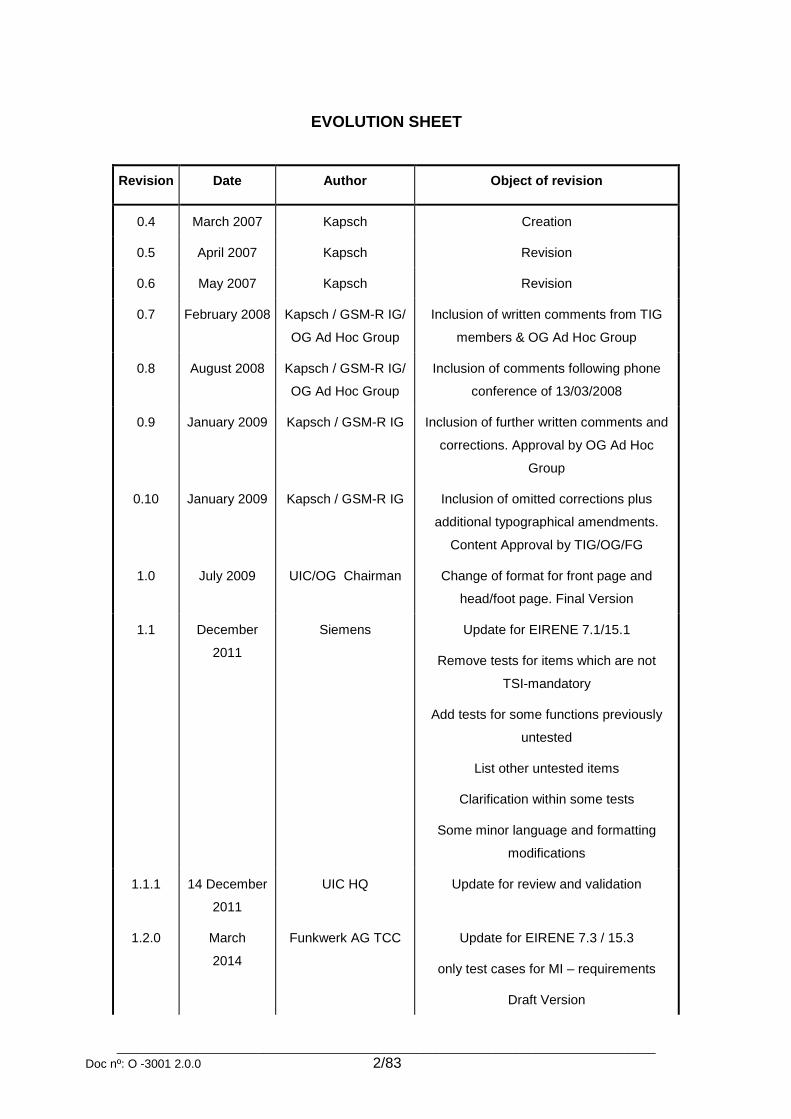
EVOLUTION SHEET
Revision Date Author Object of revision
0.4 March 2007 Kapsch Creation
0.5 April 2007 Kapsch Revision
0.6 May 2007 Kapsch Revision
0.7 February 2008 Kapsch / GSM-R IG/
OG Ad Hoc Group
Inclusion of written comments from TIG
members & OG Ad Hoc Group
0.8 August 2008 Kapsch / GSM-R IG/
OG Ad Hoc Group
Inclusion of comments following phone
conference of 13/03/2008
0.9 January 2009 Kapsch / GSM-R IG Inclusion of further written comments and
corrections. Approval by OG Ad Hoc
Group
0.10 January 2009 Kapsch / GSM-R IG Inclusion of omitted corrections plus
additional typographical amendments.
Content Approval by TIG/OG/FG
1.0 July 2009 UIC/OG Chairman Change of format for front page and
head/foot page. Final Version
1.1 December
2011
Siemens Update for EIRENE 7.1/15.1
Remove tests for items which are not
TSI-mandatory
Add tests for some functions previously
untested
List other untested items
Clarification within some tests
Some minor language and formatting
modifications
1.1.1 14 December
2011
UIC HQ Update for review and validation
1.2.0 March
2014
Funkwerk AG TCC Update for EIRENE 7.3 / 15.3
only test cases for MI – requirements
Draft Version

_________________________________________________________________________________
Doc nº: O -3001 2.0.0 3/83
1.2.1 April 2014 Funkwerk AG TCC update after review
1.3.0 Mai 2014 Funkwerk AG TCC no changes / Final Version
1.3.1 June 2014 Funkwerk AG TCC Changes after internal review
1.3.2 June 2014 Funkwerk AG TCC Changes after internal review
1.3.3 July 2014 Funkwerk AG TCC Changes after internal review
1.4.0 Sept 2014 Funkwerk AG TCC Update for EDOR
1.4.1 Oct 2014 Funkwerk AG TCC Changes after internal review
1.5.0 March 2015 Funkwerk AG TCC Update for EIRENE 7.4/15.4
1.5.1 Nov 2015 Funkwerk AG TCC Changes after internal review
1.5.2 Jan 2016 Funkwerk AG TCC Changes after internal review
1.5.3 Apr 2016 Funkwerk AG TCC Changes after internal review
1.5.4 May 2016 Funkwerk AG TCC Changes after internal review
1.5.5 June 2016 Funkwerk AG TCC Changes after review with Operators
Group
1.5.6 June 2016 Funkwerk AG TCC Changes after review with Operators
Group
2.0.0 July 2016 UIC/IG Title and approval reviewed. Approved by
UIC and IG as related to B0 R4
_________________________________________________________________________________
Doc nº: O -3001 2.0.0 4/83
Content
1 OBJECT ................................................................................................................................ 8
1.1 Purpose of the document ............................................................................................................................ 8
1.2 Abbreviations ............................................................................................................................................... 8
1.3 Reference Documents ............................................................................................................................... 10
1.4 Dedication ................................................................................................................................................... 10
2 TEST CONFIGURATION .................................................................................................... 11
2.1 Overview ..................................................................................................................................................... 11
2.2 Equipment required ................................................................................................................................... 11
2.3 Network configuration ............................................................................................................................... 11
2.4 Cab Radio and ETCS data only radio configuration ............................................................................... 12 2.4.1 Software ................................................................................................................................................ 12 2.4.2 Hardware............................................................................................................................................... 12 2.4.3 SIM cards .............................................................................................................................................. 12
3 COMPLETION OF THE FUNCTIONAL TESTS .................................................................. 12
3.1 General ........................................................................................................................................................ 12
3.2 Structure of the tests ................................................................................................................................. 12
3.3 Completion of the tests ............................................................................................................................. 13
3.4 Cab Radio test configuration .................................................................................................................... 13
3.5 ETCS data only radio test configuration ................................................................................................. 14
4 EIRENE REQUIREMENTS FOR CAB RADIO: MANDATORY FOR INTEROPERABILITY ................................................................................................................ 15
4.1 Power on / Power off functions ................................................................................................................ 15 4.1.1 System boot – error-free device ........................................................................................................... 15 4.1.2 System boot – faulty device .................................................................................................................. 15 4.1.3 Loudspeaker volume at power-on ........................................................................................................ 16 4.1.4 System boot – no GSM-(R) network coverage ..................................................................................... 16 4.1.5 Power off and back on with different network coverage ....................................................................... 17 4.1.6 Saving numbers at power-off ................................................................................................................ 17
4.2 MMI functions ............................................................................................................................................. 18 4.2.1 MMI activation ....................................................................................................................................... 18 4.2.2 MMI deactivation ................................................................................................................................... 19 4.2.3 MMI language selection ........................................................................................................................ 20

_________________________________________________________________________________
Doc nº: O -3001 2.0.0 5/83
4.3 Self-test functions ...................................................................................................................................... 21 4.3.1 Manual self-test ..................................................................................................................................... 21 4.3.2 Manual self-test – incoming call ............................................................................................................ 21
4.4 Network related features ........................................................................................................................... 22 4.4.1 Manual network selection – idle mode .................................................................................................. 22 4.4.2 Manual network selection – during ongoing call ................................................................................... 23 4.4.3 Visualisation – network loss .................................................................................................................. 23 4.4.4 Visualisation – "no EIRENE network" ................................................................................................... 23 4.4.5 Numbering plan ..................................................................................................................................... 24 4.4.6 Location Dependent Addressing ........................................................................................................... 25 4.4.7 Bearer service ....................................................................................................................................... 25
4.5 Operation in idle mode .............................................................................................................................. 26 4.5.1 Main components of the Cab Radio ..................................................................................................... 26 4.5.2 Loudspeaker volume ............................................................................................................................. 26 4.5.3 Phone number entries ........................................................................................................................... 27
4.6 Entry of train data....................................................................................................................................... 27 4.6.1 Registration of train data ....................................................................................................................... 27 4.6.2 Correction of train data ......................................................................................................................... 28 4.6.3 Re-registration after changing networks ............................................................................................... 28 4.6.4 Registration of functional address to other driver (non-leading driver) ................................................. 29 4.6.5 Registration / deregistration of stock number ....................................................................................... 30 4.6.6 Deregistration of train number .............................................................................................................. 30 4.6.7 Deregistration of train number – not successful ................................................................................... 31 4.6.8 Forced deregistration ............................................................................................................................ 31 4.6.9 Follow-me service control sequences ................................................................................................... 32 4.6.10 Registration / deregistration 10 functional numbers ............................................................................. 33
4.7 Text messaging .......................................................................................................................................... 33 4.7.1 Sending a text message using SMS teleservice................................................................................... 33 4.7.2 Receiving a text message using SMS teleservice ................................................................................ 34 4.7.3 Receiving a text message – maximum length ...................................................................................... 34 4.7.4 Receiving a text message – during PTP call ........................................................................................ 34 4.7.5 Cell Broadcast message ....................................................................................................................... 35
4.8 Point-to-Point calls..................................................................................................................................... 35 4.8.1 Incoming PTP call with eMLPP <4> using MSISDN (CLIP) ................................................................. 35 4.8.2 Incoming PTP call with eMLPP <4> and with train functional identity .................................................. 36 4.8.3 Incoming PTP call with eMLPP <4> and with engine/coach functional identity ................................... 37 4.8.4 Incoming call with eMLPP <0-3> .......................................................................................................... 37 4.8.5 Leaving or terminating incoming calls ................................................................................................... 38 4.8.6 Outgoing PTP call – MSISDN or number of fixed network user (CoLP) .............................................. 39 4.8.7 Outgoing PTP call – functional number ................................................................................................ 39 4.8.8 Outgoing PTP call – controller .............................................................................................................. 40 4.8.9 Outgoing PTP call – controller (fails) .................................................................................................... 41 4.8.10 Outgoing PTP call – train staff .............................................................................................................. 41 4.8.11 Outgoing PTP call – using the phone book .......................................................................................... 42 4.8.12 Outgoing PTP call – priorities of functional identities ........................................................................... 42 4.8.13 Terminating outgoing calls .................................................................................................................... 43 4.8.14 Incoming PTP call – during ongoing PTP call (CW / HOLD) ................................................................ 44 4.8.15 Outgoing PTP call – during ongoing PTP call....................................................................................... 44 4.8.16 Higher priority incoming call – ongoing PTP call .................................................................................. 45
4.9 Group calls .................................................................................................................................................. 46 4.9.1 Incoming voice group call ..................................................................................................................... 46 4.9.2 Incoming voice group call – “other drivers in the area” ......................................................................... 46 4.9.3 Group call participation depending on the activated GID ..................................................................... 47 4.9.4 Outgoing voice group call ..................................................................................................................... 48

_________________________________________________________________________________
Doc nº: O -3001 2.0.0 6/83
4.9.5 Outgoing voice group call – “other drivers in the area” ......................................................................... 48 4.9.6 Visualisation – "Unable to establish VGC" ............................................................................................ 49 4.9.7 Leaving voice group call ....................................................................................................................... 50 4.9.8 Terminating voice group call – “other drivers in the area” .................................................................... 50 4.9.9 Moving out of the group call area ......................................................................................................... 51
4.10 Conference calls ..................................................................................................................................... 51 4.10.1 Multiparty call (MPTY) ........................................................................................................................... 51 4.10.2 Multi-driver communication – leading driver ......................................................................................... 52 4.10.3 Multi-driver communication – other driver ............................................................................................. 52 4.10.4 Multi-driver communication – controller ................................................................................................ 53
4.11 Call arbitration ........................................................................................................................................ 54 4.11.1 Call arbitration – ongoing railway emergency call ................................................................................ 54 4.11.2 Call arbitration – ongoing high priority group call between drivers in the same area ........................... 54 4.11.3 Call arbitration – ongoing operational group call to drivers in the same area ...................................... 55 4.11.4 Call arbitration – ongoing call from a controller .................................................................................... 56 4.11.5 Call arbitration – ongoing “other drivers on same train” call ................................................................. 57 4.11.6 Call arbitration – ongoing group call in shunting mode ......................................................................... 58 4.11.7 Call arbitration – ongoing PTP call in shunting mode ........................................................................... 58
4.12 Railway emergency calls ....................................................................................................................... 59 4.12.1 Incoming railway emergency call .......................................................................................................... 59 4.12.2 Outgoing railway emergency call .......................................................................................................... 60 4.12.3 Railway emergency call – during ongoing call ...................................................................................... 61 4.12.4 Railway emergency call – leaving group call area ................................................................................ 61 4.12.5 Railway emergency call – entering group call area .............................................................................. 62 4.12.6 Railway emergency call – re-dial after unsuccessful call ..................................................................... 62 4.12.7 eREC backward compatibility ............................................................................................................... 63
4.13 Shunting mode ........................................................................................................................................ 63 4.13.1 Entering shunting mode – during ongoing call...................................................................................... 63 4.13.2 Entering shunting mode – idle mode .................................................................................................... 64 4.13.3 Shunting registration ............................................................................................................................. 64 4.13.4 Shunting registration – failed registration ............................................................................................. 65 4.13.5 Shunting group activation ..................................................................................................................... 65 4.13.6 Shunting area change – joining ongoing shunting emergency call ...................................................... 66 4.13.7 Shunting area change – during shunting group call ............................................................................. 66 4.13.8 Exiting shunting mode ........................................................................................................................... 66 4.13.9 Exiting shunting mode – during shunting group call ............................................................................. 67 4.13.10 Storage of shunting data ................................................................................................................... 68 4.13.11 Group call in shunting mode .............................................................................................................. 68 4.13.12 Link Assurance Signal ....................................................................................................................... 69
4.14 Call confirmation .................................................................................................................................... 69 4.14.1 Emergency call confirmation ................................................................................................................. 69 4.14.2 Emergency call confirmation – group call area change ........................................................................ 70 4.14.3 Emergency call confirmation – network or power loss ......................................................................... 71
5 EIRENE REQUIREMENTS FOR CAB RADIO: MANDATORY FOR INTEROPERABILITY – OPTIONAL COMPONENTS ............................................................... 72
5.1 Public Address ........................................................................................................................................... 72 5.1.1 Public Address – incoming call ............................................................................................................. 72 5.1.2 Call arbitration – ongoing public address call ....................................................................................... 72 5.1.3 Call arbitration – ongoing public address call (over radio link) ............................................................. 73
5.2 Intercom ...................................................................................................................................................... 73 5.2.1 Intercom system - incoming call ........................................................................................................... 73

_________________________________________________________________________________
Doc nº: O -3001 2.0.0 7/83
5.2.2 Call arbitration – ongoing intercom call ................................................................................................. 74 5.2.3 Call arbitration – ongoing intercom call (over radio link) ....................................................................... 74
5.3 Train-borne recorder .................................................................................................................................. 75
6 EIRENE REQUIREMENTS FOR ETCS DATA ONLY RADIO: MANDATORY FOR INTEROPERABILITY ................................................................................................................ 76
6.1 Dialling calls (ATD) ............................................................................................................................... 76 6.2 Terminating calls (ATH) ........................................................................................................................ 77 6.3 Connected line identification presentation (+COLP) ............................................................................. 77 6.4 Calling line identification presentation (+CLIP) ..................................................................................... 78 6.5 Incoming call priority presentation (+CRING) ....................................................................................... 78 6.6 Automatic answering (ATS0) ................................................................................................................ 79 6.7 Subscriber number (+CNUM) ............................................................................................................... 80 6.8 Network registration (+CREG) .............................................................................................................. 80 6.9 Operator selection (+COPS) ................................................................................................................. 81 6.10 Data call – transparent 4800 bps (V.110) ............................................................................................. 81 6.11 Data call – transparent 9600 bps (V.110) ............................................................................................. 82 6.12 Call setup with UUS1 (+CUUS1) .......................................................................................................... 82

_________________________________________________________________________________
Doc nº: O -3001 2.0.0 8/83
1 OBJECT
1.1 Purpose of the document
This document contains the test cases that are necessary for the functional validation of a Cab Radio and ETCS data only radio according to the EIRENE specifications FRS (see [2]) and SRS (see [3]). The test cases cover all the requirements that have been identified as mandatory for interoperability (MI) according to the EIRENE specification and which can be validated using functional tests. QoS and performance requirements for voice and non-safety related data communications are not in the scope of this document.
1.2 Abbreviations
AC Access Code
AT Attention command set
BC Breakout Code
BTS Base Transceiver Station
CC Country Code
CN Coach Number
CR Cab Radio
CHPC Confirmation of High Priority Calls
CLIP Calling Line Identification Presentation
CoLP Connected Line Identification Presentation
CTS Centralised Train Signalling
DSD Driver Safety Device
EDOR ETCS data only radio
EIRENE European Integrated Railway Radio Enhanced Network
eMLPP enhanced Multi-Level Precedence and Pre-emption
ETCS European Train Control System
EN Engine Number
eREC enhanced Railway Emergency Call
ETSI European Telecommunications Standards Institute
FFFIS Form Fit Functional Interface Specification
FI Functional Identity
FC Function Code
FN Functional Number
FRS Functional Requirements Specification
GCA Group Call Area
GID Group call Identity
GPH General Purpose Handheld

_________________________________________________________________________________
Doc nº: O -3001 2.0.0 9/83
GSM Global System for Mobile Communications
GSM-MT GSM Mobile Termination
GSM-R GSM-Railway, GSM train radio system
ISDN Integrated Services Digital Network
LAS Link Assurance Signal
LN Location Number
MLPP Multi-Level Precedence and Pre-emption
MMI Man – Machine Interface
MORANE Mobile Radio for Railway Networks in Europe
MPTY Multiparty Supplementary Services
MS Mobile Station, GSM-R mobile phone with a valid SIM Card for the test
NDC National Destination Code
OPH Operational Purpose Handheld
OPS Operational Purpose Handheld for Shunting
OTA Over The Air
OTDI Originator To Dispatcher Information
PA Public Address
PC Primary Controller
PFN Presentation of Functional Number
PSC Power Supply Controller
PTP Point-to-Point call
PTT Push to Talk
QoS Quality of Services
RBC Radio Block Centre
REC Railway Emergency Call
SC Secondary Controller
SEC Shunting Emergency Call
SGC Shunting Group Call
SIM Subscriber Identification Module
SMS Short Message Service
SN Stock Number
SN Subscriber Number
SRS System Requirements Specification
TE Terminal Equipment
TN Train Number
UIC Union Internationale des Chemins de Fer
USSD Unstructured Supplementary Service Data

_________________________________________________________________________________
Doc nº: O -3001 2.0.0 10/83
UUIE User-to-User Information Element
UUS User-User Signalling
VBC Voice Broadcast Call
VBS Voice Broadcast Service
VGC Voice Group Call
VGCS Voice Group Call Service
1.3 Reference Documents
[1]* Cab Radio User’s Manual
[2] UIC, EIRENE Functional Requirements Specification Doc.-N°: UIC CODE 950 | version: 7.4.0
[3] UIC, EIRENE System Requirement Specification Doc.-N°: UIC CODE 951 | version: 15.4.0
[4] COMMISSION DECISION (EU) 2015/14 of 5 January 2015 amending Decision 2012/88/EU on the technical specification for interoperability relating to the control-command and signalling subsystems of the trans-European rail system
[5] No longer used
[6] No longer used
[7] No longer used
[8] No longer used
[9] No longer used
[10] UIC, Loudspeaker and telephone systems in RIC coaches - Standard technical characteristics Doc.-N°: UIC CODE 568 | version: 3 (1996-01)
[11] No longer used
[12] No longer used
[13] UIC, FFFIS for GSM-R SIM Cards Doc.-N°: P38 T 9001 | version: 5.0 (2015-12)
* Document [1] refers to the User’s Manual of the tested type of Cab Radio. It is imperative to use the User’s Manual corresponding to the tested version of the Cab Radio.
1.4 Dedication
This document is based on Nortel – Applikationtests Cab Radio and HFWK – Cab Radio Application Tests and HFWK – Testhandbuch Add-on to UIC O-3001 which are kindly provided by Nortel and Funkwerk AG TCC (Hörmann Funkwerk Kölleda before) and improved by Funkwerk AG TCC.

_________________________________________________________________________________
Doc nº: O -3001 2.0.0 11/83
2 Test Configuration
2.1 Overview
Following components of the EIRENE GSM-R system are needed to execute the tests:
GSM-R Network(s)
Cab Radio or ETCS data only radio (device under test)
General purpose radio (GPH) or operational purpose radio (OPH)
Shunting radio (OPS)
Dispatchers
ISDN termination (RBC)
SIM Cards
2.2 Equipment required
GSM-R network(s) operating in the R-GSM 900 band.
GSM Abis-tracer or GSM A-tracer, in order to check the contents on the messages exchanged between mobiles and network when required.
One Cab Radio or ETCS data only radio (device under test).
One fixed network Controller (dispatcher).
One ISDN termination (RBC).
Enough mobile stations (Cab Radio or handheld) to cover multiparty calls e.g. drivers multi-party call (MPTY).
GSM-R SIM cards with all the services and features provisioned and configured for the appropriate mobile user and function.
SIM card editor, in order to be able to modify the services and features provisioned and the configuration on the SIM cards for the different test requirements.
User’s Manual of the tested device.
User’s Manual of the other mobiles involved testing.
2.3 Network configuration
The GSM-R network (or in some test cases, the two GSM-R networks) needs to be compliant to the requirements
listed in the set of specifications applicable to GSM-R networks, included in [4]. It needs to support all of the different
configurations required to execute the Cab Radio and ETCS data only radio test cases. It must be possible to adjust
various functions within the network in order to carry out the Cab Radio and ETCS data only radio tests.
The stationary work stations, especially for the primary controller, secondary controller, power supply controller, traffic
controller and high priority call acknowledgement centre belong to the test environment and are provided by the test lab
operator or the customer.
The configuration of the used GSM-R network, supplier and the software release of the network components such as
e.g. network switching subsystem, base station subsystem etc. must be documented in the test protocol.

_________________________________________________________________________________
Doc nº: O -3001 2.0.0 12/83
2.4 Cab Radio and ETCS data only radio configuration
2.4.1 Software
The software release of the ETCS data only radio or the Cab Radio and particular releases of the components and MMIs must be declared in the test protocol.
2.4.2 Hardware
The hardware release of the ETCS data only radio or the Cab Radio and the MMI must be declared in the test protocol.
2.4.3 SIM cards
The SIM cards need to be compliant to [13] and will be provided by the network operator or test lab operator.
3 Completion of the FUNCTIONAL tests
3.1 General
The following chapters contain a detailed description of all functional tests provided for the Cab Radio and for the ETCS data only radio.
3.2 Structure of the tests
The tests are structured as follows:
test title
purpose of the test
precondition for the test
reference to specific requirement(s)
completion of the test in individual steps
overall result on the results sheet (Appendix A)
Where the term “User’s Manual” is used, the required action and/or any audible and/or visual indication has to be referred to the User’s Manual of the tested ETCS data only radio or Cab Radio.
_________________________________________________________________________________
Doc nº: O -3001 2.0.0 13/83
3.3 Completion of the tests
The tests are carried out with at least one Cab Radio (CR-A) or ETCS data only radio (EDOR). In case that more Cab Radios are necessary for the test execution (CR-B, CR-C) the test case mentions this. If other subscribers are used they are identified by MS-A, MS-B, MS-C (for mobile subscribers) or TE1, TE2 (for terminal equipments). The entire series of tests has to be completed successfully once. The order of the tests during the test run might vary. If the result of a test case is PASSED then it does not need to be redone. If the result of a test case is FAILED the test case needs to be retested. If the 1st test result is FAILED and the 2nd result is PASSED then the test case needs to be retested again. The test case is passed only if the result was PASSED already at 1st test execution or PASSED within 2nd and 3rd execution. Where the procedure section of a test case contains “-none–“ that means no action to be performed on the tested device, only on other devices (e.g. CR-B or MS-A). The priority and severity management of an issue that caused the test to fail is not subject of this document.
3.4 Cab Radio test configuration
The following global requirements or settings apply to the Cab Radio test grouping:
Test system requirements:
1 EIRENE compliant GSM-R network (or in some test cases two networks) compliant to [4]
2 Subscriber for controller calls 1200, 1300 & 1400
3 Two primary controller (PC1, PC2) in different cell specific routing areas
4 Shunting radio with LAS function
5 Cab Radio
6 Handhelds
7 Public address and intercom system in accordance with [10] (connected to the test unit if it supports it)
8 SIM card editor, in order to be able to modify the services and features provisioned and the configuration on the
SIM cards for the different test requirements.
9 External device for setting the test unit’s vehicle number (e.g. personal computer with appropriate software
installed)
10 The interface between the application and GSM-R modem can be recorded (is required, e.g. for testing the
correct format of the UUIE)
Test unit requirements
11 Equipped with a plug-in SIM card according to [13] (FFFIS for GSM-R SIM cards)
12 Group number 299 for railway emergency call, 599 for shunting emergency call (SEC) configured on the SIM
13 Additional group numbers (e.g. 203) are enabled on the SIM
14 Voice broadcast groups (e.g. 200 or 998) are enabled on the SIM
15 Own phone number (MSISDN) entered on the SIM
16 Registered engine number entered on the SIM and on the network
17 Short numbers for the controllers have to be defined in the SIM (EFSDN) file, as defined in MORANE FFFIS for
GSM-R SIM cards.
18 Unless otherwise specified CR is switched on and in Train Radio Mode (unless Shunting Radio Mode is
specified in precondition), MMI1 is activated, idle mode, registered as the lead vehicle.
_________________________________________________________________________________
Doc nº: O -3001 2.0.0 14/83
Further requirements
SMS SIM cards of CR & MS are activated
SMS service centre number is saved on CR & MS SIM cards
SIM of CR & MS does not contain any received SMS messages
Follow-Me feature must be activated on SIM Card.
The following GIDs should be defined on SIM cards, and in network database:
- national usage group: CT(50)+GCA+GID (600-699)
- default train group: CT(50)+GCA+GID (200)
- default maintenance group: CT(50)+GCA+GID (560)
- default shunting group: CT(50)+GCA+GID (500)
- dedicated maintenance group: CT(50)+GCA+GID (561-568)
- dedicated shunting group: CT(50)+GCA+GID (501-529)
- national broadcast group: CT(51)+GCA+GID (400-499)
- train broadcast group: CT(51)+GCA+GID (200)
- maintenance broadcast group: CT(51)+GCA+GID (600-699)
If required, the necessary deviations are listed in the individual test cases. The used test environment shall be
documented in the test report.
3.5 ETCS data only radio test configuration
The following requirements or settings apply to the ETCS data only radio test grouping:
Test system requirements:
1 EIRENE compliant GSM-R network (or in some test cases two networks) compliant to [4] 2 ETCS data only radio 3 Terminal equipments 4 The interface between the application and GSM-R modem can be recorded
Test unit requirements
1 Equipped with a plug-in SIM card according to [5] (FFFIS for GSM-R SIM cards) 2 Own phone number (MSISDN) entered on the SIM 3 Notifications of voice broadcast and voice group calls should be prevented by the SIM-card configuration for the
ETCS-Application. This ensures that the data flow is not disturbed by notifications 4 ETCS data only radio is switched on unless other state is specified in precondition
Further requirements
The tests will be performed with a test application (e.g. with a terminal software) connected through a serial interface to the test equipment. With this test application manual AT commands or predefined scripts can be sent to the test equipment. The feedback of the test equipment will be outputted to the test application through the same interface. If required, the necessary deviations are listed in the individual test cases. The used test environment shall be documented in the test report.

_________________________________________________________________________________
Doc nº: O -3001 2.0.0 15/83
4 EIRENE Requirements for Cab Radio: Mandatory for Interoperability
4.1 Power on / Power off functions
4.1.1 System boot – error-free device
Purpose: This test is to show the system start-up procedure and the default settings of an error-free Cab
Radio.
Precondition: General test configuration. Cab radio is powered off and all units are error-free.
References:
EIRENE FRS :
EIRENE SRS :
ETSI :
§ 5.2.3.1, 5.2.3.13
§ 4.4.1, 5.4.1, 5.4.2
EN 301 515, TS 100 906
Step Procedure Result / Effect
1 Power on CR-A
- Indication of the start-up procedure visible on the MMI
- Automatic self-test
- Network registration to the previously registered network
2 - none - (Initialisation finished)
- MMI default settings initialised (e.g. brightness, audio profile, loudspeaker volume, handset volume)
- Default user language selected
- Acoustic signal: ready for operation
- Last used network selected
- Name of the network and indication of the adequate signal strength is displayed on the MMI
4.1.2 System boot – faulty device
Purpose: This test is to show that the automatic self-test during system start-up identifies a faulty device and
the according error message is displayed on the MMI.
Precondition: General test configuration. An artificial defect shall be implanted into the CR-A according to
documentation (e.g. remove the Public Address and Intercom Unit).
Attention: To prepare this test, the CR-A system must be electrically powered off.
References:
EIRENE FRS :
EIRENE SRS :
§ 5.2.3.1
§ 5.4.1

_________________________________________________________________________________
Doc nº: O -3001 2.0.0 16/83
Step Procedure Result / Effect
1 Power on CR-A
- Indication of the start-up procedure is displayed on the MMI
- Automatic self-test
2 - none - (Initialisation finished)
- MMI default settings initialised
- Default user language selected
- Acoustic signal: ready for operation
- Name of the network displayed on the MMI.
- Error message - according to user’s manual – is displayed on the MMI
4.1.3 Loudspeaker volume at power-on Purpose: This test is to show that after a system start-up, the Cab Radio automatically selects the default
loudspeaker volume.
Precondition: General test configuration.
References:
EIRENE FRS :
EIRENE SRS :
§ 5.2.3.17
§ 5.4.1i
Step Procedure Result / Effect
1a Set the loudspeaker volume using MMI menu
or external device to „Quiet cab” or equivalent
Loudspeaker volume set to the selected level 1b Set the loudspeaker volume using MMI menu
or external device to „Normal cab” or equivalent
1c Set the loudspeaker volume using MMI menu
or external device to „Noisy cab” or equivalent
2 Power off CR-A CR-A powered off
3 Power on CR-A Loudspeaker volume at the same level as before
4.1.4 System boot – no GSM-(R) network coverage
Purpose: This test is to show that after a system start-up an audible and visual indication is given if connection
to a GSM-(R) network is not possible.
Precondition: General test configuration. The antenna cable should be removed from the GSM-MT antenna
connector or the network coverage of the BTS should be switched off (Radio Signal < -110dBm).
Attention: To prepare this test, the Cab Radio must be electrically powered off.
References:
EIRENE FRS :
EIRENE SRS :
§ 5.2.3.1
§ 5.4.3

_________________________________________________________________________________
Doc nº: O -3001 2.0.0 17/83
Step Procedure Result / Effect
1 Power on CR-A
- Indication of the start-up procedure is displayed on the MMI
- Automatic self-test
2 - none - (initialisation finished)
- MMI default settings initialised
- Default user language selected
- Audio-visual indication of no GSM-(R) coverage
- Error message is displayed on the MMI
4.1.5 Power off and back on with different network coverage Purpose: This test is to show that after the Cab Radio is powered off it is no longer connected to the GSM-(R)
network and after it is powered on again the corresponding network availability is displayed on the
MMI.
Precondition: General test configuration; Manual network selection is configured. CR-A has a registered engine
and train number.
References:
EIRENE FRS :
§ 5.2.3.1, 5.2.3.3
Step Procedure Result / Effect
1 Power-off CR-A CR-A powered off
2a - none –
(MS-A calls CR-A by MSISDN) No connection to CR-A
2b - none –
(MS-A calls CR-A by engine number)
3a Power-on CR-A (previous network available) - Audible indication is given
- Network name is displayed on the MMI.
3b Power-on CR-A (only other network available)
- Audio-visual indication is given for the unavailability of the last used network
- Manual network selection needed for connecting to other network
4.1.6 Saving numbers at power-off
Purpose: This test is to show that if the Cab Radio is powered off the last used numbers are saved.
Precondition: General test configuration; Manual network selection is configured; Cab Radio registered to
CT4/CT3/CT2 functional numbers according to the test steps.
References:
EIRENE FRS :
§ 5.2.3.4
Step Procedure Result / Effect
1a Power-off CR-A
(CR-A registered only by CT4) CR-A powered off
1b Power-off CR-A
(CR-A registered only by CT3)

_________________________________________________________________________________
Doc nº: O -3001 2.0.0 18/83
1c Power-off CR-A
(CR-A registered by CT2)
2 Power-on CR-A CR-A powered on and in default idle status
3a - none -
(Controller initiates a call to CR-A by CT4)
- Call established, communication possible
- CR-A sends correct PFN Tag5 to Controller 3b
- none -
(Controller initiates a call to CR-A by CT3)
3c - none -
(Controller initiates a call to CR-A by CT2)
4 Power-off CR-A CR-A powered off
5
- none -
(CR-A’s CT2 registration is removed from
subscription handling entity)
- none -
(CR-A powered off)
6 Power-on CR-A - CR-A powered on and in default idle status
- No Train Number is displayed on the MMI
7
CR-A initiates a call to Controller - Call established, communication possible
- CR-A sends PFN Tag5 with CT3/CT4 to Controller
4.2 MMI functions
4.2.1 MMI activation
Purpose: This test is to show that the MMI can be activated using a soft switch-on function.
Precondition: General test configuration. CR-A is powered on and its MMI is switched off (inactive). MMI of CR-A is
inactive. MMI reset timer is set to t minutes.
References:
EIRENE FRS :
§ 5.2.3.6, 5.2.3.7
Step Procedure Result / Effect
1 (MMI was switched off with non-default settings) Switch on the MMI
- Indication of the switch-on procedure
- Self-test of the MMI
2a - none - (MMI was switched off less than t minutes ago)
MMI powers on with the same configuration as before (e.g. previously set brightness / contrast / volume levels)
2b - none - (MMI was switched off more than t minutes ago)
MMI powers on with the default configuration (e.g. default brightness / contrast / volume levels)

_________________________________________________________________________________
Doc nº: O -3001 2.0.0 19/83
4.2.2 MMI deactivation Purpose: This test is to show that the MMI can be deactivated by a soft switch-off function during an active call
which is terminated or left by the Cab Radio. Deregistration of the train number in shunting mode
only possible if train number is already registered during shunting.
Precondition: General test configuration; CR-A in train mode for steps 1-14 and later in shunting mode for steps 5-
14;
References:
EIRENE FRS :
§ 5.2.3.5, 5.2.3.9
Step Procedure Result / Effect
PTP / Voice Broadcast Call
1 CR-A registers a CT2 number CR-A has a CT2 registration
2a - none -
(Incoming broadcast call GID 20X) Call established, communication possible
2b CR-A initiates a PTP call to MS-A
3a During the active call, switch-off the MMI
(e.g. by using CR-A’s reversing switch or MMI’s
power switch, and if required by the user’s
manual, confirm deregistration of CT2 number )
- Active MMI becomes passive
- Broadcast call left
- Deregistration of the CT2 number
- Save data
3b
- Active MMI becomes passive
- PTP call terminated
- Deregistration of the CT2 number
- Save data
4
Switch-on the MMI
(e.g. by using CR-A’s reversing switch or MMI’s
power switch)
- MMI becomes active again
- CR-A in default idle status without CT2 registration
Voice Group Call
5 CR-A registers a CT2 / CT6 number CR-A has a CT2 / CT6 registration
6a - none -
(Incoming group call GID 200 / 50X) Call established, communication possible
6b CR-A initiates a group call GID 200 / 50X
7a - none -
(uplink is taken by MS-A) MS-A can be heard on CR-A
7b (uplink is free)
CR-A press and hold PTT button CR-A can be heard on MS-A
8a During the active call, switch-off the MMI
(e.g. by using CR-A’s reversing switch or MMI’s
power switch, and if required by the user’s
manual, confirm deregistration of CT2 number)
- Active MMI becomes passive
- Group call left
- Deregistration of the CT2 number
- Save data
8b
- Active MMI becomes passive
- Group call terminated
- Deregistration of the CT2 number Save data
9
Switch-on the MMI
(e.g. by using CR-A’s reversing switch or MMI’s
power switch)
- MMI becomes active again
- CR-A in default idle status without CT2 registration
Railway Emergency Call
10 CR-A registers a CT2 / CT6 number CR-A has a CT2 / CT6 registration

_________________________________________________________________________________
Doc nº: O -3001 2.0.0 20/83
11a - none -
(Incoming emergency call GID 299 / 599) Call established, communication possible
11b CR-A initiates an emergency call GID 299 / 599
12a - none -
(uplink is taken by MS-A) MS-A can be heard on CR-A
12b (uplink is free)
CR-A press and hold PTT button CR-A can be heard on MS-A
13a
During the active call, switch-off the MMI
(e.g. b y using CR-A’s reversing switch or
MMI’s power switch, and if required by the
user’s manual, confirm deregistration of CT2
number)
Preferred Implementation – call is left immediately:
- Active MMI becomes passive
- Emergency call left
- Deregistration of the CT2 number
- Save data
- CHPC is sent with Tag5 containing CT2 / CT6 number and with CAUSE 0x10 (call was left on user command)
Optional Implementation – call is not left:
- No change until the call is terminated by another party
- After call termination active MMI becomes passive
- Deregistration of the CT2 number
- Save data
- CHPC is sent with Tag5 containing CT2 / CT6 number and with CAUSE 0x00 (no error)
13b
- Active MMI becomes passive
- Emergency call terminated
- Deregistration of the CT2 number
- Save data
- CHPC is sent with Tag5 containing CT2 / CT6 number and with CAUSE 0x00 (no error)
14
Switch-on the MMI
(e.g. by using CR-A’s reversing switch or MMI’s
power switch)
- MMI becomes active again
- CR-A in default idle status without CT2 registration
4.2.3 MMI language selection
Purpose: This test is to show that the Cab Radio supports at least ten different languages on the MMI for
related prompts and information to be displayed. The user can select the preferred language from a
list of available languages.
Precondition: General test configuration. CR-A is loaded with at least 10 different languages options.
References:
EIRENE FRS :
§ 5.2.3.12, 5.2.13, 5.2.3.14, 5.2.3.16
Step Procedure Result / Effect
1 CR-A activates MMI language selection - List of available languages are displayed on the MMI
- There are at least 10 different language options
2 CR-A selects and activates a different language than the currently used language
Information, prompts and menu items are changed to the selected language on the MMI
_________________________________________________________________________________
Doc nº: O -3001 2.0.0 21/83
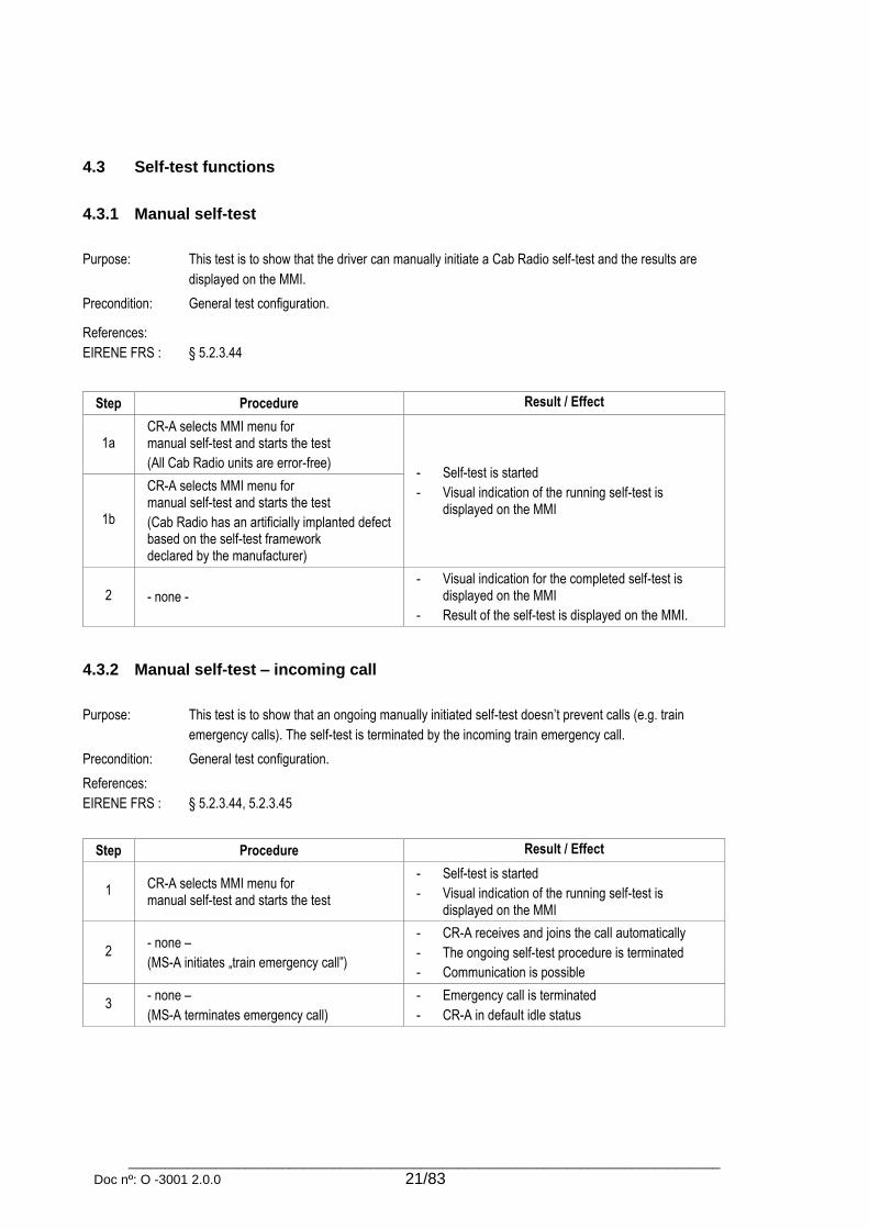
4.3 Self-test functions
4.3.1 Manual self-test
Purpose: This test is to show that the driver can manually initiate a Cab Radio self-test and the results are
displayed on the MMI.
Precondition: General test configuration.
References:
EIRENE FRS :
§ 5.2.3.44
Step Procedure Result / Effect
1a CR-A selects MMI menu for manual self-test and starts the test
(All Cab Radio units are error-free) - Self-test is started
- Visual indication of the running self-test is displayed on the MMI
1b
CR-A selects MMI menu for manual self-test and starts the test
(Cab Radio has an artificially implanted defect based on the self-test framework declared by the manufacturer)
2 - none -
- Visual indication for the completed self-test is displayed on the MMI
- Result of the self-test is displayed on the MMI.
4.3.2 Manual self-test – incoming call
Purpose: This test is to show that an ongoing manually initiated self-test doesn’t prevent calls (e.g. train
emergency calls). The self-test is terminated by the incoming train emergency call.
Precondition: General test configuration.
References:
EIRENE FRS :
§ 5.2.3.44, 5.2.3.45
Step Procedure Result / Effect
1 CR-A selects MMI menu for manual self-test and starts the test
- Self-test is started
- Visual indication of the running self-test is displayed on the MMI
2 - none –
(MS-A initiates „train emergency call”)
- CR-A receives and joins the call automatically
- The ongoing self-test procedure is terminated
- Communication is possible
3 - none –
(MS-A terminates emergency call)
- Emergency call is terminated
- CR-A in default idle status

_________________________________________________________________________________
Doc nº: O -3001 2.0.0 22/83
4.4 Network related features
4.4.1 Manual network selection – idle mode
Purpose: This test is to show that the driver can select an authorised mobile radio network manually from a
prioritised list using MMI action and the Cab Radio can roam between EIRENE networks.
Precondition: General test configuration. Prioritised list of all authorised mobile radio networks should be stored on
the SIM of CR-A. At least two GSM-R networks should be available and connected together so the
de-registration command can be routed from one network to the other.
References:
EIRENE FRS :
EIRENE SRS :
ETSI :
MORANE :
§ 5.2.3.23, 5.2.3.23i, 5.2.3.25, 10.5.1, 11.3.4.1, 11.3.4.2, 11.3.4.3
§ 5.6.1i, 10.5.1, 11.3.14, 11.3.15
EN 300 940, TS 100 929, TS 122 030
P 38 T 9001
Step Procedure Result / Effect
1 CR-A starts manual network selection using a simple MMI action
Preferred Implementation: A prioritised list of all authorised mobile radio networks that are stored on the SIM is displayed in the following order:
- Home EIRENE network
- Foreign EIRENE networks
- Non-EIRENE networks
Optional Implementation: A prioritised list of authorised mobile radio networks that are stored on the SIM and are available at the current location is displayed in the following order:
- Home EIRENE network
- Foreign EIRENE networks
- Non-EIRENE networks
2 CR-A selects an authorised network and starts changing the network
Network selection procedure started
3 - none -
- Network selection is executed
- Registration of on-train functional numbers based on the train number are executed
- After successful registration, de-registration on the previous network are executed
- Progress of actions may be displayed on the MMI
- New network name is displayed on the MMI
- New registration information is displayed on the MMI
- CR-A returns to default idle status

_________________________________________________________________________________
Doc nº: O -3001 2.0.0 23/83
4.4.2 Manual network selection – during ongoing call
Purpose: This test is to show that the manual network selection function is not available when there are
ongoing calls involving the Cab Radio.
Preconditions: General test configuration. CR-A is in an ongoing call with MS-A.
References:
EIRENE FRS :
EIRENE SRS :
§ 5.2.3.24
§ 5.6.1i
Step Procedure Result / Effect
1 CR-A starts manual network change using MMI menu
Network selection menu is not available
Network selection menu is available but network change is not started
2 - none - - Network not changed
- CR-A continues the call
4.4.3 Visualisation – network loss Purpose: This test is to show that loss of the GSM-R network is indicated audio-visually.
Purpose: General test configuration
References:
EIRENE FRS :
EIRENE SRS :
ETSI :
§ 5.4.16
§ 4.4.1, 5.6.6
TS 100 906
Step Procedure Result / Effect
1a Network coverage breaks off
(CR-A in train radio mode) - Visual indication for no signal strength is
displayed on the MMI
- Audio-visual indication for the network loss is displayed on the MMI 1b
Network coverage breaks off
(CR-A in shunting radio mode)
2a Restore network coverage
CR-A in idle train mode
2b CR-A in idle shunting mode
4.4.4 Visualisation – "no EIRENE network"
Purpose: This test is to show that the usage of networks with limited EIRENE functionality is clearly indicated
to the driver.
Purpose: General test configuration
Network with limited EIRENE functions is selectable from the SIM
References:
EIRENE FRS :
§ 10.5.2

_________________________________________________________________________________
Doc nº: O -3001 2.0.0 24/83
Step Procedure Result / Effect
1 CR-A changes the used network to
a network with limited EIRENE functions
- Network change indicated audio-visually
- Visual indication of the limited EIRENE functionality – according to user’s manual – is displayed on the MMI
4.4.5 Numbering plan
Purpose: This test is to show the correct handling of Numbering plan:
The correct handling of Group IDs
The correct handling of National EIRENE Numbers
The correct handling of international EIRENE Numbers
The correct handling of different Functional numbers and function Codes
Precondition: General test configuration. MS-A registered to TN / EN / CN or a maintenance team member or a
national usage team member, according to the specific test steps.
References:
EIRENE FRS :
EIRENE SRS :
ITU-T :
UIC :
§ 9.2.1.1, 9.2.1.2, 9.2.2.2, 9.2.3.2, 9.2.4.1, 9.3.1, 9.3.2, 10.4.4, 11.2.1.1
§ 4.3.3., 4.3.4, 9.2.2, 9.2.4, 9.2.7, 9.2.9, 9.2.12, 9.4.1, 9.5.3, 9.6.3, 9.6.4, 9.7.1, 9.9.2, 9A.2, 9A.3,
11.2.3
E.164
438-1, 438-3
Step Procedure Result / Effect
1 CR-A initiate a PTP call to MS-A using MSISDN: CT(8) + SN
- Call established successfully
- Communication possible
- CR-A terminates the initiated call
2 CR-A initiate a PTP call to MS-A using Train Number: CT(2) + TN + FC
3 CR-A initiate a PTP call to MS-A using Engine Number: CT(3) + EN + FC
4 CR-A initiate a PTP call to MS-A using Coach Number: CT(4) + CN + FC
5 CR-A initiate a PTP call to MS-A using Shunting team number: CT(6) + LN +FC(5xxx)
6 (activate “high priority group call between drivers in the same area” for CR-A)
CR-A initiate a group call GID 200
7 (activate “operational group call to drivers in the same area” for CR-A)
CR-A initiate a group call GID 555

_________________________________________________________________________________
Doc nº: O -3001 2.0.0 25/83
8 (switch CR-A to shunting and activate “default shunting group”)
CR-A initiate a group call GID 500
9 (activate “dedicated shunting group” for CR-A)
CR-A initiate a group call GID 50X
4.4.6 Location Dependent Addressing
Purpose: This test is to show that if the Cab Radio initiates a call to the primary controller then this call is being
routed to the controller corresponding to the current cell specific routing area
Precondition: General test configuration.
References:
EIRENE FRS :
EIRENE SRS :
§ 4.2.4, 11.4.1, 11.4.4
§ 11.7.2
Step Procedure Result / Effect
1 (CR-A is in the location of PC1)
CR-A initiate a call to the Primary Controller The call is initiated to the selected controller (PC1)
2 - none –
(PC1 terminates the call) The call is terminated with an audio-visual indication
3 (CR-A moves into the location of PC2)
CR-A initiate a call to the Primary Controller The call is initiated to the selected controller (PC2)
4.4.7 Bearer service Purpose: This test is to show that the Cab Radio can receive data transmissions with different data rates.
Precondition: General test configuration; Data transfer call configured on MS-A (e.g. with
"AT+CBST=<speed>,<name>,<ce>") and data call initiated from MS-A (e.g. with "ATD+MSISDN")
. Network supports GSM bearer services:
- 24: Asynchronous 2.4 kbps Transparent (e.g. "AT+CBST=4,0,0")
- 25: Asynchronous 4.8 kbps Transparent (e.g. "AT+CBST=6,0,0")
- 26: Asynchronous 9.6 kbps Transparent (e.g. "AT+CBST=7,0,0")
References:
EIRENE SRS :
ETSI :
§ 4.3.2
EN 300 904
Step Procedure Result / Effect
1a
- none -
(incoming Asynchronous Transparent
data call to CR-A with 2.4 kbps) Call established, data transfer possible
1b
- none -
(incoming Asynchronous Transparent
data call to CR-A with 4.8 kbps)

_________________________________________________________________________________
Doc nº: O -3001 2.0.0 26/83
1c
- none -
(incoming Asynchronous Transparent
data call to CR-A with 9.6 kbps)
4.5 Operation in idle mode
4.5.1 Main components of the Cab Radio
Purpose: This test is to show that the main components of the Cab Radio are all in place and working.
Precondition: General test configuration
References:
EIRENE FRS :
EIRENE SRS :
§ 5.4.1
§ 4.1.3.1, 5.2.2.1
Step Procedure Result / Effect
1
Check the following components of CR-A:
- display
- control panel
- loudspeaker
- handset with PTT button
Components of CR-A are all in place and working.
2 CR-A initiate a call to MS-A - Call established, communication possible
- GSM-MT air interface is working correctly
4.5.2 Loudspeaker volume
Purpose: This test is to show that the volume of the Cab Radio loudspeaker can be adjusted manually.
Precondition: General test configuration.
References:
EIRENE FRS :
§ 5.2.3.18
Step Procedure Result / Effect
1 - none –
(Incoming PTP call to CR-A) Call established, communication possible
2 Select volume settings for CR-A loudspeaker Loudspeaker volume setting is activated
3a Increase loudspeaker volume Loudspeaker volume increased.
3b Decrease loudspeaker volume Loudspeaker volume is decreased.

_________________________________________________________________________________
Doc nº: O -3001 2.0.0 27/83
4.5.3 Phone number entries Purpose: This test is to show that the Cab Radio can access saved numbers and call lists.
Purpose: General test configuration
References:
EIRENE FRS :
EIRENE SRS :
§ 5.2.3.39, 5.2.3.40
§ 5.5.16
Step Procedure Result / Effect
1 CR-A opens the MMI menu
for managing phone numbers
The following functions at least are available in this menu.
The order can differ and individual functions can also be
swapped out in separate menus (e.g. VGCS), which are
reached using additional soft keys (see user’s manual):
- Phone book
- Phone number entry (manual dialling)
- Call list
- VGCS calls
- Driver conferences
4.6 Entry of train data
4.6.1 Registration of train data
Purpose: This test is to show that the leading driver can register a train number for the Cab Radio.
Precondition: General test configuration ; CR-A not registered to any train number previously
References:
EIRENE FRS :
EIRENE SRS :
ETSI :
MORANE :
§ 5.2.3.26, 5.2.3.27, 5.2.3.34, 11.2.2.2, 11.3.2.1, 11.3.2.2
§ 4.3.3, 4.3.4, 9.2.4, 11.3.5
EN 300 952, EN 300 957, TS 100 950, TS 122 094, TS 123 087, TS 124 090
E 10 T 6001, E 12 T 6001
Step Procedure Result / Effect
1 CR-A selects train data entry menu - Train data entry menu activated on the MMI
2 Enter train number and confirm. - Only numbers can be entered
- Train number displayed on the MMI
3 Enter the function code for leading driver and confirm
Train function displayed on the MMI
4 Start registration
- Train number registration started using USSD messages and protocols
- Registration progress is displayed on the MMI
- Indication of the successful registration is sent back to CR-A
- Registration status is displayed on the MMI
5 - none –
(MS-A initiates a PTP call to CR-A by Train Number and Function Code)
Call established, communication is possible
_________________________________________________________________________________
Doc nº: O -3001 2.0.0 28/83
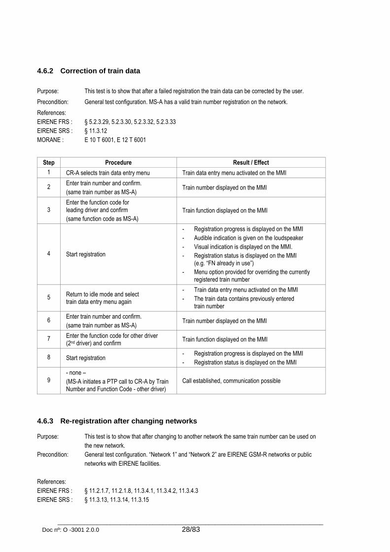
4.6.2 Correction of train data
Purpose: This test is to show that after a failed registration the train data can be corrected by the user.
Precondition: General test configuration. MS-A has a valid train number registration on the network.
References:
EIRENE FRS :
EIRENE SRS :
MORANE :
§ 5.2.3.29, 5.2.3.30, 5.2.3.32, 5.2.3.33
§ 11.3.12
E 10 T 6001, E 12 T 6001
Step Procedure Result / Effect
1 CR-A selects train data entry menu Train data entry menu activated on the MMI
2 Enter train number and confirm.
(same train number as MS-A) Train number displayed on the MMI
3 Enter the function code for leading driver and confirm
(same function code as MS-A)
Train function displayed on the MMI
4 Start registration
- Registration progress is displayed on the MMI
- Audible indication is given on the loudspeaker
- Visual indication is displayed on the MMI.
- Registration status is displayed on the MMI (e.g. “FN already in use”)
- Menu option provided for overriding the currently registered train number
5 Return to idle mode and select train data entry menu again
- Train data entry menu activated on the MMI
- The train data contains previously entered train number
6 Enter train number and confirm.
(same train number as MS-A) Train number displayed on the MMI
7 Enter the function code for other driver (2nd driver) and confirm
Train function displayed on the MMI
8 Start registration - Registration progress is displayed on the MMI
- Registration status is displayed on the MMI
9 - none –
(MS-A initiates a PTP call to CR-A by Train Number and Function Code - other driver)
Call established, communication possible
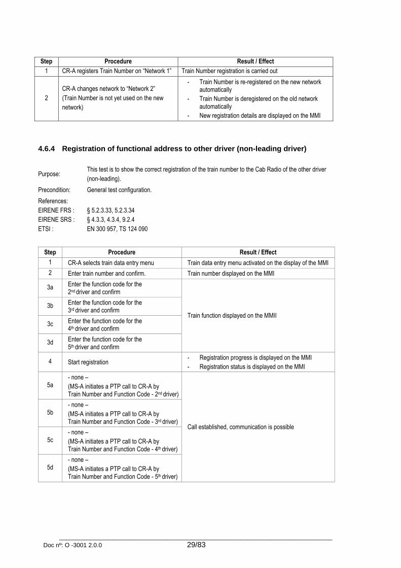
4.6.3 Re-registration after changing networks Purpose: This test is to show that after changing to another network the same train number can be used on
the new network.
Precondition: General test configuration. “Network 1” and “Network 2” are EIRENE GSM-R networks or public
networks with EIRENE facilities.
References:
EIRENE FRS :
EIRENE SRS :
§ 11.2.1.7, 11.2.1.8, 11.3.4.1, 11.3.4.2, 11.3.4.3
§ 11.3.13, 11.3.14, 11.3.15
_________________________________________________________________________________
Doc nº: O -3001 2.0.0 29/83
Step Procedure Result / Effect
1 CR-A registers Train Number on “Network 1” Train Number registration is carried out
2
CR-A changes network to “Network 2”
(Train Number is not yet used on the new
network)
- Train Number is re-registered on the new network automatically
- Train Number is deregistered on the old network automatically
- New registration details are displayed on the MMI
4.6.4 Registration of functional address to other driver (non-leading driver)
Purpose: This test is to show the correct registration of the train number to the Cab Radio of the other driver
(non-leading).
Precondition: General test configuration.
References:
EIRENE FRS :
EIRENE SRS :
ETSI :
§ 5.2.3.33, 5.2.3.34
§ 4.3.3, 4.3.4, 9.2.4
EN 300 957, TS 124 090
Step Procedure Result / Effect
1 CR-A selects train data entry menu Train data entry menu activated on the display of the MMI
2 Enter train number and confirm. Train number displayed on the MMI
3a Enter the function code for the 2nd driver and confirm
Train function displayed on the MMII
3b Enter the function code for the 3rd driver and confirm
3c Enter the function code for the 4th driver and confirm
3d Enter the function code for the 5th driver and confirm
4 Start registration - Registration progress is displayed on the MMI
- Registration status is displayed on the MMI
5a - none –
(MS-A initiates a PTP call to CR-A by Train Number and Function Code - 2nd driver)
Call established, communication is possible
5b - none –
(MS-A initiates a PTP call to CR-A by Train Number and Function Code - 3rd driver)
5c - none –
(MS-A initiates a PTP call to CR-A by Train Number and Function Code - 4th driver)
5d - none –
(MS-A initiates a PTP call to CR-A by Train Number and Function Code - 5th driver)
_________________________________________________________________________________
Doc nº: O -3001 2.0.0 30/83
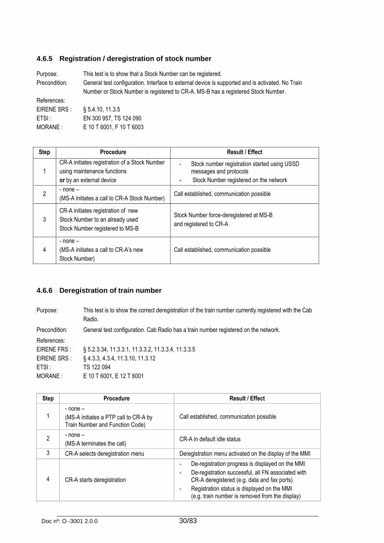
4.6.5 Registration / deregistration of stock number Purpose: This test is to show that a Stock Number can be registered.
Precondition: General test configuration. Interface to external device is supported and is activated. No Train
Number or Stock Number is registered to CR-A. MS-B has a registered Stock Number.
References:
EIRENE SRS :
ETSI :
MORANE :
§ 5.4.10, 11.3.5
EN 300 957, TS 124 090
E 10 T 6001, F 10 T 6003
Step Procedure Result / Effect
1
CR-A initiates registration of a Stock Number
using maintenance functions
or by an external device
- Stock number registration started using USSD messages and protocols
- Stock Number registered on the network
2 - none –
(MS-A initiates a call to CR-A Stock Number) Call established, communication possible
3
CR-A initiates registration of new
Stock Number to an already used
Stock Number registered to MS-B
Stock Number force-deregistered at MS-B
and registered to CR-A
4
- none –
(MS-A initiates a call to CR-A’s new
Stock Number)
Call established, communication possible
4.6.6 Deregistration of train number
Purpose: This test is to show the correct deregistration of the train number currently registered with the Cab
Radio.
Precondition: General test configuration. Cab Radio has a train number registered on the network.
References:
EIRENE FRS :
EIRENE SRS :
ETSI :
MORANE :
§ 5.2.3.34, 11.3.3.1, 11.3.3.2, 11.3.3.4, 11.3.3.5
§ 4.3.3, 4.3.4, 11.3.10, 11.3.12
TS 122 094
E 10 T 6001, E 12 T 6001
Step Procedure Result / Effect
1 - none –
(MS-A initiates a PTP call to CR-A by Train Number and Function Code)
Call established, communication possible
2 - none –
(MS-A terminates the call) CR-A in default idle status
3 CR-A selects deregistration menu Deregistration menu activated on the display of the MMI
4 CR-A starts deregistration
- De-registration progress is displayed on the MMI
- De-registration successful, all FN associated with CR-A deregistered (e.g. data and fax ports)
- Registration status is displayed on the MMI (e.g. train number is removed from the display)

_________________________________________________________________________________
Doc nº: O -3001 2.0.0 31/83
5 - none –
(MS-A initiates a PTP call to CR-A by Train Number and Function Code)
PTP call cannot be established
4.6.7 Deregistration of train number – not successful Purpose: This test is to show that the Cab Radio receives the result and cause after a failed deregistration.
Precondition:
General test configuration; Cab Radio has a train number registered on the network.
Deregistration must be barred on the network or the GSM service must be deactivated.
References:
EIRENE SRS :
ETSI :
MORANE :
§ 11.3.12
EN 300 952, TS 100 950
E 12 T 6001
Step Procedure Result / Effect
1 CR-A selects deregistration menu Deregistration menu activated on the display of the MMI
2 CR-A start deregistration.
(deregistration fails)
- Deregistration progress is displayed on the MMI
- Registration status is displayed at the MMI
4.6.8 Forced deregistration
Purpose: This test is to show that the Cab Radio can be forced to register to an already registered (assigned)
functional number. (e.g. train number)
Precondition: General test configuration. MS-A has a train number registered on the network.
References:
EIRENE FRS :
EIRENE SRS :
ETSI :
MORANE :
§ 5.2.3.29, 5.2.3.30, 5.2.3.31, 11.3.2.5, 11.3.3.4, 11.3.3.5
§ 11.3.9i
TS 100 549, TS 123 090
E 10 T 6001
Step Procedure Result / Effect
1 CR-A selects train data entry menu Train data entry menu activated on the display of the MMI
2 Enter train number and confirm
(same train number as MS-A) Train number displayed on the MMI
3 Enter the function code for leading driver and confirm
(same function code as MS-A)
Train function displayed on the MMI
4 Start registration
- Registration progress is displayed on the MMI
- Audible indication is given on the loudspeaker
- Visual indication is displayed on the MMI
- Registration status is displayed on the MMI (e.g. “FN already in use”)
- Menu option provided for overriding the currently registered train number

_________________________________________________________________________________
Doc nº: O -3001 2.0.0 32/83
5 Start forced deregistration (optional user action on MS-A to confirm the forced de-registration)
Forced deregistration progress started in the background:
- Sends interrogation message
- Receive MSISDN from the network
- Send a forced de-registration message
- Receive the answer
- Send a registration message
- Receive the answer
Registration progress is displayed on the MMI
Registration status is displayed on the MMI
6 - none –
(MS-A initiates a PTP call to CR-A by Train Number and Function Code)
Call established, communication is possible
7 - none –
(MS-A terminates the call) CR-A in default idle status
8
- none –
(MS-A registers to the train number associated with CR-A and performs a forced deregistration)
- Audio-visual indication of the forced deregistration is displayed on the MMI
- CR-A in default idle status
4.6.9 Follow-me service control sequences
Purpose: This test is to show that the Cab Radio manages the Functional Number changes using the Follow-
me service control sequences. These functions can be used by MMI menu or by external device.
Precondition: General test configuration. Cab Radio and ABIS trace or protocol analyzer.
References:
EIRENE FRS :
EIRENE SRS :
ETSI :
MORANE :
§ 11.3.3.4
§ 4.3.3, 5.4.7, 5.4.8, 5.4.9, 5.4.11, 11.3.2, 11.3.7
TS 100 625, TS 100 916, TS 122 090, TS 123 094, TS 124 080, TS 127 007
E 10 T 6001, E 12 T 6001
Step Procedure Result / Effect
1 CR-A starts registration of FN
- FN registration procedure successful
- Cab Radio trace contains "AT+CUSD" message: * * 214 * SI * * * # (where SI= International EIRENE Number) or ABIS trace contains “DATIN” message with “2A95..”
2 CR-A starts deregistration of FN
- FN de-registration procedure successful
- Cab Radio trace contains "AT+CUSD" message: # # 214 * SI * * * # (where SI= International EIRENE Number) or ABIS trace contains “DATIN” message with “A391..”
3 CR-A starts interrogation of FN
- Interrogation procedure successful
- Cab Radio trace contains "AT+CUSD" message: * # 214 * SI * * * # (where SI= International EIRENE Number) or ABIS trace contains “DATIN” message with “AA91..”

_________________________________________________________________________________
Doc nº: O -3001 2.0.0 33/83
4 CR-A changes network and starts re-registration of FN
- FN re-registration procedure successful
- Cab Radio trace contains "AT+CUSD" message: * * 214 * SI * * * # followed by # # 214 * SI * * * #
(where SI= International EIRENE Number) or ABIS trace contains “DATIN” message with “2A95..” and later with “A391..”
5 CR-A starts forced de-registration of FN
- FN forced de-registration procedure successful
- Cab Radio trace contains "AT+CUSD" message: # # 214 * SI * 88 * MSISDN * # (where SI= International EIRENE Number) or ABIS trace contains “DATIN” message with “A391..”
4.6.10 Registration / deregistration 10 functional numbers Purpose: This test is to show that it is possible to register up to ten Functional Numbers to items of
equipment physically connected to the Cab Radio within 30 seconds and after it can be also deregistered within 30 seconds.
Precondition:
General test configuration. Cab Radio has no FN registered on the network.
References: EIRENE FRS: MORANE
§ 11.3.2.3, 11.3.3.3 E 10 T 6001
Step Procedure Result / Effect
1
CR-A starts registration procedure for 10 different Functional Numbers (individually, collectively or by external device)
Registration started and finished within 30 seconds
2
CR-A starts deregistration procedure for 10 different Functional Numbers (individually, collectively or by external device)
Deregistration started and finished within 30 seconds
4.7 Text messaging
4.7.1 Sending a text message using SMS teleservice
Purpose: This test is to show that the Cab Radio can send text messages using teleservice SMS.
Precondition: General test configuration.
References:
EIRENE FRS :
EIRENE SRS :
ETSI :
§ 4.2.2, 12.2.2
§ 4.3.1, 12.2.1, 12.2.2
TS 100 905
Step Procedure Result / Effect
1 CR-A sends text message containing 160 characters to MS-A using MMI menu or by external device
- Text message sent from CR-A
- MS-A receives text message containing all 160 characters
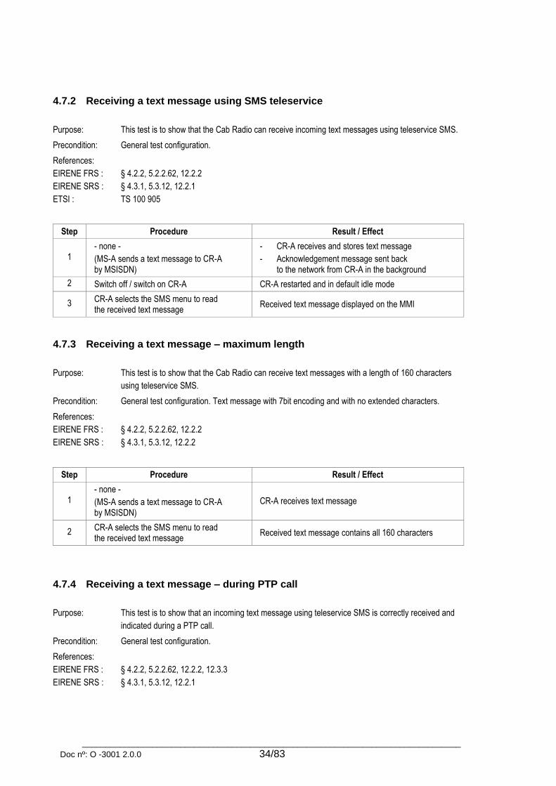
_________________________________________________________________________________
Doc nº: O -3001 2.0.0 34/83
4.7.2 Receiving a text message using SMS teleservice
Purpose: This test is to show that the Cab Radio can receive incoming text messages using teleservice SMS.
Precondition: General test configuration.
References:
EIRENE FRS :
EIRENE SRS :
ETSI :
§ 4.2.2, 5.2.2.62, 12.2.2
§ 4.3.1, 5.3.12, 12.2.1
TS 100 905
Step Procedure Result / Effect
1 - none -
(MS-A sends a text message to CR-A by MSISDN)
- CR-A receives and stores text message
- Acknowledgement message sent back to the network from CR-A in the background
2 Switch off / switch on CR-A CR-A restarted and in default idle mode
3 CR-A selects the SMS menu to read the received text message
Received text message displayed on the MMI
4.7.3 Receiving a text message – maximum length
Purpose: This test is to show that the Cab Radio can receive text messages with a length of 160 characters
using teleservice SMS.
Precondition: General test configuration. Text message with 7bit encoding and with no extended characters.
References:
EIRENE FRS :
EIRENE SRS :
§ 4.2.2, 5.2.2.62, 12.2.2
§ 4.3.1, 5.3.12, 12.2.2
Step Procedure Result / Effect
1 - none -
(MS-A sends a text message to CR-A by MSISDN)
CR-A receives text message
2 CR-A selects the SMS menu to read the received text message
Received text message contains all 160 characters
4.7.4 Receiving a text message – during PTP call
Purpose: This test is to show that an incoming text message using teleservice SMS is correctly received and
indicated during a PTP call.
Precondition: General test configuration.
References:
EIRENE FRS :
EIRENE SRS :
§ 4.2.2, 5.2.2.62, 12.2.2, 12.3.3
§ 4.3.1, 5.3.12, 12.2.1
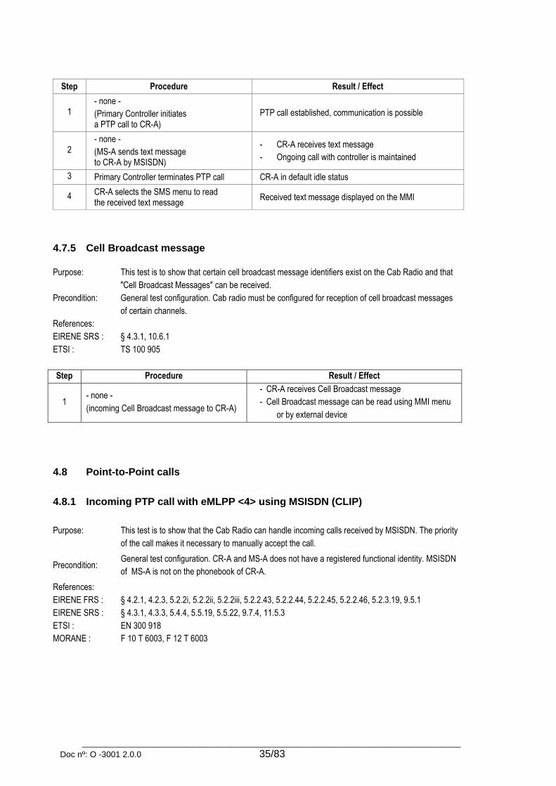
_________________________________________________________________________________
Doc nº: O -3001 2.0.0 35/83
Step Procedure Result / Effect
1 - none -
(Primary Controller initiates a PTP call to CR-A)
PTP call established, communication is possible
2 - none -
(MS-A sends text message to CR-A by MSISDN)
- CR-A receives text message
- Ongoing call with controller is maintained
3 Primary Controller terminates PTP call CR-A in default idle status
4 CR-A selects the SMS menu to read the received text message
Received text message displayed on the MMI
4.7.5 Cell Broadcast message
Purpose: This test is to show that certain cell broadcast message identifiers exist on the Cab Radio and that
"Cell Broadcast Messages" can be received.
Precondition: General test configuration. Cab radio must be configured for reception of cell broadcast messages
of certain channels.
References:
EIRENE SRS :
ETSI :
§ 4.3.1, 10.6.1
TS 100 905
Step Procedure Result / Effect
1 - none -
(incoming Cell Broadcast message to CR-A)
- CR-A receives Cell Broadcast message
- Cell Broadcast message can be read using MMI menu
or by external device
4.8 Point-to-Point calls
4.8.1 Incoming PTP call with eMLPP <4> using MSISDN (CLIP)
Purpose: This test is to show that the Cab Radio can handle incoming calls received by MSISDN. The priority
of the call makes it necessary to manually accept the call.
Precondition: General test configuration. CR-A and MS-A does not have a registered functional identity. MSISDN
of MS-A is not on the phonebook of CR-A.
References:
EIRENE FRS :
EIRENE SRS :
ETSI :
MORANE :
§ 4.2.1, 4.2.3, 5.2.2i, 5.2.2ii, 5.2.2iii, 5.2.2.43, 5.2.2.44, 5.2.2.45, 5.2.2.46, 5.2.3.19, 9.5.1
§ 4.3.1, 4.3.3, 5.4.4, 5.5.19, 5.5.22, 9.7.4, 11.5.3
EN 300 918
F 10 T 6003, F 12 T 6003
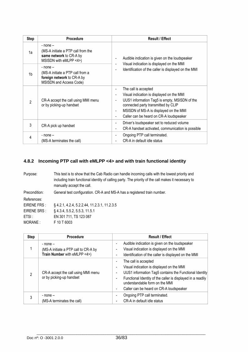
_________________________________________________________________________________
Doc nº: O -3001 2.0.0 36/83
Step Procedure Result / Effect
1a
- none –
(MS-A initiate a PTP call from the same network to CR-A by MSISDN with eMLPP <4>)
- Audible indication is given on the loudspeaker
- Visual indication is displayed on the MMI
- Identification of the caller is displayed on the MMI 1b
- none –
(MS-A initiate a PTP call from a foreign network to CR-A by MSISDN and Access Code)
2 CR-A accept the call using MMI menu or by picking-up handset
- The call is accepted
- Visual indication is displayed on the MMI
- UUS1 information Tag5 is empty, MSISDN of the connected party transmitted by CLIP
- MSISDN of MS-A is displayed on the MMI
- Caller can be heard on CR-A loudspeaker
3 CR-A pick up handset - Driver’s loudspeaker set to reduced volume
- CR-A handset activated, communication is possible
4 - none –
(MS-A terminates the call)
- Ongoing PTP call terminated.
- CR-A in default idle status
4.8.2 Incoming PTP call with eMLPP <4> and with train functional identity
Purpose: This test is to show that the Cab Radio can handle incoming calls with the lowest priority and
including train functional identity of calling party. The priority of the call makes it necessary to
manually accept the call.
Precondition: General test configuration. CR-A and MS-A has a registered train number.
References:
EIRENE FRS :
EIRENE SRS :
ETSI :
MORANE :
§ 4.2.1, 4.2.4, 5.2.2.44, 11.2.3.1, 11.2.3.5
§ 4.3.4, 5.5.2, 5.5.3, 11.5.1
EN 301 711, TS 123 087
F 10 T 6003
Step Procedure Result / Effect
1 - none –
(MS-A initiate a PTP call to CR-A by Train Number with eMLPP <4>)
- Audible indication is given on the loudspeaker
- Visual indication is displayed on the MMI
- Identification of the caller is displayed on the MMI
2 CR-A accept the call using MMI menu or by picking-up handset
- The call is accepted
- Visual indication is displayed on the MMI
- UUS1 information Tag5 contains the Functional Identity
- Functional Identity of the caller is displayed in a readily understandable form on the MMI
- Caller can be heard on CR-A loudspeaker
3 - none –
(MS-A terminates the call)
- Ongoing PTP call terminated.
- CR-A in default idle status

_________________________________________________________________________________
Doc nº: O -3001 2.0.0 37/83
4.8.3 Incoming PTP call with eMLPP <4> and with engine/coach functional identity
Purpose: This test is to show that the Cab Radio can handle incoming calls with the lowest priority and
including engine/coach functional identity of calling party. The priority of the call makes it
necessary to manually accept the call.
Precondition: General test configuration. CR-A is functionally registered to engine/coach number.
References:
EIRENE SRS :
§ 5.4.4
Step Procedure Result / Effect
1a - none –
(MS-A initiate a PTP call to CR-A by Engine Number with eMLPP <4>)
- Audible indication is given on the loudspeaker
- Visual indication is displayed on the MMI
- Identification of the caller is displayed on the MMI 1b
- none –
(MS-A initiate a PTP call to CR-A by Coach Number with eMLPP <4>)
2 CR-A accept the call using MMI menu or by picking-up handset
- The call is accepted
- Visual indication is displayed on the MMI
- Identification of the caller is displayed on the MMI
- Caller can be heard on CR-A loudspeaker
3 - none –
(MS-A terminates the call)
- Ongoing PTP call terminated.
- CR-A in default idle status
4.8.4 Incoming call with eMLPP <0-3>
Purpose: This test is to show that the Cab Radio can handle incoming calls with priority higher than 4. The call
has to be automatically accepted if the call priority is of or exceeds a predefined priority level. (for
Cab Radio this priority is eMLPP <3>)
Precondition: General test configuration.
References:
EIRENE FRS :
EIRENE SRS :
ETSI :
§ 4.2.3
§ 4.3.3, 5.5.2, 10.2.1
EN 122 067, EN 300 918, EN 300 924, TS 124 008, TS 127 007
Step Procedure Result / Effect
1a - none –
(incoming call to CR-A with eMLPP <3>) - Audible indication is given on the loudspeaker
- Visual indication is displayed on the MMI
- CR-A automatically accept the call if the priority is of or exceeds a defined priority level
- Identification of the caller is displayed on the MMI
1b - none –
(incoming call to CR-A with eMLPP <2>)
1c - none –
(incoming call to CR-A with eMLPP <1>)
1d - none –
(incoming call to CR-A with eMLPP <0>)
2 - none –
(caller party terminates the call) CR-A in default idle status

_________________________________________________________________________________
Doc nº: O -3001 2.0.0 38/83
4.8.5 Leaving or terminating incoming calls
Purpose: This test is to show that the Cab Radio can end or leave incoming calls in different ways.
Precondition: General test configuration;
References:
EIRENE FRS :
EIRENE SRS :
§ 5.2.2.34, 5.2.2.60
§ 5.5.3, 5.5.23, 5.5.24, 5.5.26, 5A.3
Step Procedure Result / Effect
PTP call
1 CR-A receives a PTP call
Pick up handset Communication possible
2
The following actions are carried out:
a) Hang up handset
b) Press "End" button
a-b) Call terminated
Multi-party call
3 CR-A receives a MPTY call
Pick up handset Communication possible
4
The following actions are carried out:
a) Hang up handset
b) Press "End" button
a-b) CR-A leaves the call
(call terminated if there was only two subscribers in it)
Group call
5 CR-A receives a VGC
Pick up handset Communication possible
6
The following actions are carried out:
a) Hang up handset.
b) Press "End" button
a) VGC placed on the loudspeaker
b) CR-A leaves the call
Drivers conference (other drivers on the same train)
7 CR-A receives a driver’s conference call
Pick up handset Communication possible
8
The following actions are carried out:
a) Hang up handset
b) Press "End" button
a) Call placed on the loudspeaker
b) CR-A leaves the call
(call terminated if there was only two subscribers in it)
Emergency call
9 CR-A receives an emergency call (GID 299)
Pick up handset Communication possible
10
The following actions are carried out:
a) Hang up handset
b) Press "End" button
a) Emergency call placed on the loudspeaker
b) No change, emergency call remains active

_________________________________________________________________________________
Doc nº: O -3001 2.0.0 39/83
4.8.6 Outgoing PTP call – MSISDN or number of fixed network user (CoLP)
Purpose: This test is to show that the Cab Radio can initiate calls by dialling a MSISDN number and the call is
established with eMLPP <4>.
Precondition: General test configuration. CR-A and MS-A does not have a registered functional identity.
References:
EIRENE FRS :
EIRENE SRS :
ETSI :
MORANE :
§ 4.2.1, 5.2.2.42, 10.2.1, 10.2.2
§ 4.3.3, 5.3.11, 5.5.4, 5.5.14, 5.5.17, 5.5.18, 10.2.1, 11.5.6
EN 300 918, TS 100 905
F 10 T 6003
Step Procedure Result / Effect
1a CR-A initiates a call to MS-A by CT(8) + SN - Audible indication is given on the loudspeaker
- Visual indication is displayed on the MMI 1b CR-A initiates a call to fixed network user
(B-Party) by dialling its telephone number
2 - none –
(MS-A/B-Party accepts the call)
- Call established to MS-A/B-Party with eMLPP <4>
- Visual indication is displayed on the MMI
- UUS1 information Tag5 is empty, MSISDN of the connected party transmitted by CoLP
- MSISDN of the connected party is displayed on the MMI
- MS-A/B-Party can be heard on the loudspeaker
3 MS-A/B-Party terminates the call - Ongoing call terminated.
- CR-A in default idle status
4.8.7 Outgoing PTP call – functional number
Purpose: This test is to show that the Cab Radio can initiate calls by dialling a functional number and the call
established with eMLPP <4>
Precondition: General test configuration. CR-A and MS-A has a registered functional identity.
References:
EIRENE FRS :
EIRENE SRS :
ETSI :
MORANE :
§ 4.2.1, 5.2.2.42, 11.2.3.1
§ 5.5.4, 5.5.14, 5.5.15, 11.5.1, 11.5.2, 11.5.4, 11.5.5
EN 300 940
F 10 T 6001, F 10 T 6003
Step Procedure Result / Effect
1 CR-A initiates a call to MS-A by dialling its Functional Number
- Audible indication is given on the loudspeaker
- Visual indication is displayed on the MMI
2 - none -
(MS-A accepts the call)
- Call established to MS-A with eMLPP <4>
- Visual indication is displayed on the MMI
- UUS1 information Tag5 contains the Functional Identity
- Functional Identity of the connected party is displayed on the MMI
- MS-A can be heard on the loudspeaker
3 CR-A pick up handset - Loudspeaker set to reduced volume
- CR-A handset activated, communication possible

_________________________________________________________________________________
Doc nº: O -3001 2.0.0 40/83
4 - none –
(MS-A terminates the call)
- Ongoing call terminated
- CR-A in default idle status
4.8.8 Outgoing PTP call – controller
Purpose: This test is to show that the Cab Radio can initiate calls to any types of controllers with a minimum
driver action (e.g. a single keystroke) and the call established with eMLPP <3>
Precondition: General test configuration. . Call to Train Management Centre is only possible if an ERTMS/ETCS
system is connected to the Cab Radio.
References:
EIRENE FRS :
EIRENE SRS :
ETSI :
MORANE :
§ 4.2.1, 4.2.4, 5.2.2i, 5.2.2ii, 5.2.2iii, 5.2.2.1, 5.2.2.3, 5.2.2.3i; 5.2.2.4, 5.2.2.5, 5.2.2.6, 5.2.2.7,
5.2.4.4, 5.2.4.9, 5.4.3, 9.3.2, 10.2.1, 10.2.2, 11.4.1, 11.4.2, 11.4.5
§ 5.3.1, 5.3.2, 5.5.1, 5.5.4, 5.5.6, 9.4.1, 9.8.1, 9.8.2, 9.8.3, 9.8.4
TS 100 950, TS 124 008
F 10 T 6001
Step Procedure Result / Effect
1a CR-A initiates a call to Primary Controller (no Functional Number registered to CR-A)
- Call dialled out with the correct four digit short code (12xx – PC, 13xx – SC, 14xx – PSC, 15xx – RBC)
- Audible indication is given on the loudspeaker
- Visual indication is displayed on the MMI
1b CR-A initiates a call to Secondary Controller (Engine Number registered to CR-A)
1c CR-A initiates a call to
Power Supply Controller (Train Number registered to CR-A)
1d CR-A initiates a call to Train Management Centre (e.g. RBC, CTS) (Train Number registered to CR-A)
2 - none –
(Controller accepts the call)
- Call established to controller with eMLPP <3>
- Visual indication is displayed on the MMI
- Identification of the connected party is displayed on the MMI of CR-A
- Identification of the connected party is displayed on the display of controller (TN / EN / MSISDN)
- Controller can be heard on the loudspeaker
3 CR-A pick up handset
- Loudspeaker set to reduced volume
- Communication to controller is activated on the handset of the CR-A
4 - none –
(Controller terminates the call)
- Ongoing call terminated.
- CR-A in default idle status

_________________________________________________________________________________
Doc nº: O -3001 2.0.0 41/83
4.8.9 Outgoing PTP call – controller (fails)
Purpose: This test is to show that if the system cannot connect the call to a controller, an appropriate audible
and visual indication is provided to the driver.
Precondition: General test configuration.
References:
EIRENE FRS :
§ 5.2.2.1, 5.2.2.8
Step Procedure Result / Effect
1a CR-A initiates a call to Primary Controller
- Audible indication is given on the loudspeaker
- Visual indication is displayed on the MMI
1b CR-A initiates a call to Secondary Controller
1c CR-A initiates a call to Power Supply Controller
2 - none –
(Call is not established)
- Call cannot be established
- Audible indication is given on the loudspeaker
- Visual indication is displayed on the MMI
- CR-A in default idle status
4.8.10 Outgoing PTP call – train staff
Purpose: This test is to show that the Cab Radio can initiate calls from a reconfigurable list of stored numbers
and perform abbreviated dialling to named user identities.
Precondition: General test configuration; CR-A and Chief Conductor are registered to the same Train Number.
References:
EIRENE FRS :
EIRENE SRS :
§ 4.2.1, 5.2.2.38, 5.2.2.39, 5.2.2.40, 5.2.3.39, 5.2.3.40
§ 5.3.10, 5.5.4, 5.5.6, 5.5.9, 5.5.16
Step Procedure Result / Effect
1 CR-A activates function for calling train staff using the MMI
- List of the trains ‘generic’ staff is displayed on the MMI (e.g. chief conductor; conductor; catering staff)
2 CR-A selects Chief Conductor from the list and initiates a call to it
- Call initiated to CR-A’s Train Number with FC10
- Audible indication is given on the loudspeaker
- Visual indication is displayed on the MMI
3 - none –
(Chief Conductor accepts the call)
- Call established with eMLPP <3> using CT2 to the registered train number and the corresponding FC
- Visual indication is displayed on the MMI
- Identification of the connected party is displayed on the MMI
4 - none –
(Chief Conductor terminates the call)
- Ongoing call terminated.
- CR-A in default idle status

_________________________________________________________________________________
Doc nº: O -3001 2.0.0 42/83
4.8.11 Outgoing PTP call – using the phone book
Purpose: This test is to show that the Cab Radio can initiate calls from the phone book of the SIM card.
Precondition: General test configuration
References:
EIRENE FRS :
EIRENE SRS :
§ 5.2.2.42, 5.2.3.39, 5.2.3.40
§ 5.5.4, 5.5.9, 5.5.11, 5.5.12, 5.5.13
Step Procedure Result / Effect
1 CR-A opens the phone book
using MMI menu Phone book opened, all entries are available.
2a CR-A selects the first phone book entry
and initiates a call to it
Voice calls are dialled and established with correct eMLPP
or
if the subscriber is not available on the network the reason
for the connection failure is signalled.
2b CR-A initiates a PTP call
by phone book entry
2c CR-A initiates a VGCS call
by phone book entry
2d CR-A initiates a VBS call
by phone book entry (optional)
4.8.12 Outgoing PTP call – priorities of functional identities
Purpose: This test is to show that the registered train number of the Cab Radio has priority over other
functional numbers. The functional number registration situations need to be created as described in
the test step. Then a call should be initiated to another subscriber.
Precondition: General test configuration
References:
EIRENE FRS :
EIRENE SRS :
MORANE :
§ 5.2.2.3i, 11.2.3.4
§ 4.3.3
F 10 T 6003
Step Train number
(CT2)
Engine number
(CT3)
Coach number
(CT4)
Result
(FN in display) Comment
1 Not registered Not registered Not registered No FN (MSISDN)
Check the
UUS1 data of
the SETUP
message
2 Registered Not registered Not registered CT2 (Train number)
3 Registered Not registered Registered CT2 (Train number)
4 Registered Registered Registered Not applicable
5 Registered Registered Not registered CT2 (Train number)
6 Not registered Registered Not registered CT3 (Engine number)
7 Not registered Registered Registered Not applicable
8 Not registered Not registered Registered CT4 (Coach number)
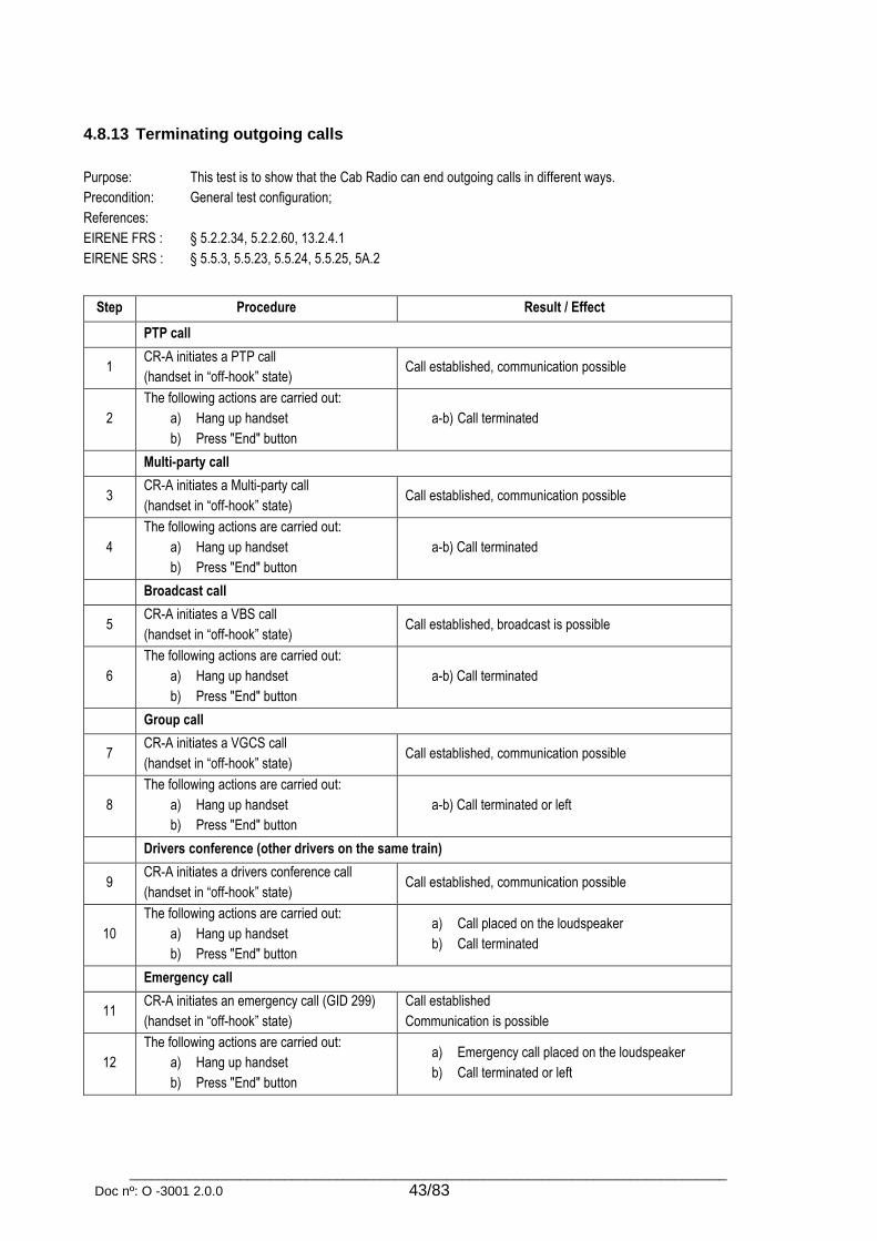
_________________________________________________________________________________
Doc nº: O -3001 2.0.0 43/83
4.8.13 Terminating outgoing calls
Purpose: This test is to show that the Cab Radio can end outgoing calls in different ways.
Precondition: General test configuration;
References:
EIRENE FRS :
EIRENE SRS :
§ 5.2.2.34, 5.2.2.60, 13.2.4.1
§ 5.5.3, 5.5.23, 5.5.24, 5.5.25, 5A.2
Step Procedure Result / Effect
PTP call
1 CR-A initiates a PTP call
(handset in “off-hook” state) Call established, communication possible
2
The following actions are carried out:
a) Hang up handset
b) Press "End" button
a-b) Call terminated
Multi-party call
3 CR-A initiates a Multi-party call
(handset in “off-hook” state) Call established, communication possible
4
The following actions are carried out:
a) Hang up handset
b) Press "End" button
a-b) Call terminated
Broadcast call
5 CR-A initiates a VBS call
(handset in “off-hook” state) Call established, broadcast is possible
6
The following actions are carried out:
a) Hang up handset
b) Press "End" button
a-b) Call terminated
Group call
7 CR-A initiates a VGCS call
(handset in “off-hook” state) Call established, communication possible
8
The following actions are carried out:
a) Hang up handset
b) Press "End" button
a-b) Call terminated or left
Drivers conference (other drivers on the same train)
9 CR-A initiates a drivers conference call
(handset in “off-hook” state) Call established, communication possible
10
The following actions are carried out:
a) Hang up handset
b) Press "End" button
a) Call placed on the loudspeaker
b) Call terminated
Emergency call
11 CR-A initiates an emergency call (GID 299)
(handset in “off-hook” state)
Call established
Communication is possible
12
The following actions are carried out:
a) Hang up handset
b) Press "End" button
a) Emergency call placed on the loudspeaker
b) Call terminated or left

_________________________________________________________________________________
Doc nº: O -3001 2.0.0 44/83
4.8.14 Incoming PTP call – during ongoing PTP call (CW / HOLD)
Purpose: This test is to show that the Cab Radio manages call wait and call hold for incoming PTP voice calls
during an ongoing PTP voice call with the same or with lower priority.
Precondition: General test configuration.
References:
EIRENE FRS :
EIRENE SRS :
ETSI :
§ 4.2.3, 5.2.3.42
§ 4.3.3
EN 300 918, EN 301 702, TS 122 087, TS 127 007
Step Procedure Result / Effect
1a (MS-A initiate a PTP call to CR-A by MSISDN with eMLPP <4>)
CR-A accept the call Call established, communication possible
1b (MS-A initiate a PTP call to CR-A by MSISDN with eMLPP <3>)
CR-A accept the call
2 - none –
(MS-B initiate a PTP call (2nd call) to CR-A by MSISDN with eMLPP <4>)
- Audible indication is given on the loudspeaker
- Visual indication is displayed on the MMI
- Details of the new incoming call are displayed on the MMI
3 CR-A accept the call by MMI menu
- Call from MS-A (1st call) put on hold
- Displayed information on the MMI is updated
- Call from MS-B is active, communication is possible
4 CR-A swap calls by MMI menu
- Call from MS-B (2nd call) put on hold
- Displayed information on the MMI is updated
- Call from MS-A (1st call) is active again, communication possible
5 CR-A swap calls again by MMI menu
- Call from MS-A (1st call) put on hold
- Displayed information on the MMI is updated
- Call from MS-B (2nd call) is active again, communication possible
6 CR-A terminates call using the MMI menu
- Call from MS-B (2nd call) is terminated
- Displayed information on the MMI is updated
- Call from MS-A (1st call) is active again
7 CR-A terminates call by hanging-up handset - Call from MS-A (1st call) is terminated
- CR-A in default idle status
4.8.15 Outgoing PTP call – during ongoing PTP call
Purpose: This test is to show that a PTP call can be placed on hold and a second PTP call can be initiated.
Precondition: General test configuration.
References:
EIRENE FRS :
EIRENE SRS :
§ 4.2.3, 5.2.3.42
§ 4.3.3

_________________________________________________________________________________
Doc nº: O -3001 2.0.0 45/83
Step Procedure Result / Effect
1 (MS-A initiate a PTP call to CR-A by MSISDN with eMLPP <4>)
CR-A accept the call
Call established, communication possible
2 CR-A puts the ongoing call on hold and initiate 2nd PTP call with eMLPP<4> to MS-B
- Call from MS-A (1st call) put on hold
- Details of the new outgoing call are displayed on the MMI
3 - none –
(MS-B accept the call)
- Visual indication is displayed on the MMI
- Identification of MS-B is displayed on the MMI
- Call to MS-B (2nd call) is active, communication possible
4 CR-A terminates call using the MMI menu - Call to MS-B (2nd call) is terminated
- Displayed information on the MMI is updated
5 CR-A retrieve the call to MS-A (previously put on hold) automatically or by user action (implementation option)
Call from MS-A (1st call) is active again, communication possible
6 CR-A terminates call by hanging-up handset - Call from MS-A (1st call) is terminated
- CR-A in default idle status
4.8.16 Higher priority incoming call – ongoing PTP call
Purpose: This test is to show that an ongoing PTP call should be either put on hold or cleared down in case of
a higher priority incoming call
Precondition: General test configuration.
References:
EIRENE FRS :
EIRENE SRS :
ETSI :
§ 5.2.4.5, 5.2.4.6
§ 4.3.3
EN 122 067, EN 300 924
Step Procedure Result / Effect
1 (MS-A initiate a PTP call to CR-A by MSISDN with eMLPP <4>)
CR-A accept the call
Call established, communication is possible
2a
- none –
(incoming PTP call to CR-A with eMLPP <3>)
Implementation option “put on hold”:
- First call is put on hold
- Automatic acceptance of second call
- Communication is possible
2b
Implementation option “clear down”:
- First call is terminated
- Automatic acceptance of second call
- Communication is possible

_________________________________________________________________________________
Doc nº: O -3001 2.0.0 46/83
4.9 Group calls
4.9.1 Incoming voice group call
Purpose: This test is to show that the group call subscribed and activated on the Cab Radio is received and
managed correctly.
Precondition: General test configuration. CR-A’s GID of the VGC 20X is activated.
References:
EIRENE FRS :
EIRENE SRS :
ETSI :
§ 4.2.1, 5.2.2.47, 5.2.2.48, 5.2.2.49, 5.2.2.51, 5.2.2.52, 5.2.2.54, 5.2.2.61, 11.2.3.2
§ 4.3.1, 5.5.19
EN 300 925, TS 100 925, TS 100 932, TS 100 933
Step Procedure Result / Effect
1 CR-A handset is in “on-hook” state
(MS-A initiates VGC 20X with eMLPP<3>)
- CR-A receives the call and accepts it automatically
- Audible indication is given on the loudspeaker
- Visual indication including GID is displayed on the MMI
- MS-A can be heard on CR-A’s loudspeaker
- Indication to use PTT to talk is displayed on the MMI
2 CR-A pick up handset - Loudspeaker set to reduced volume
- Communication is activated on the handset
3 CR-A press PTT button
(uplink is busy)
- Audible indication is given on the loudspeaker
- Visual indication (e.g. “Uplink busy”) is displayed on the MMI
4 CR-A press PTT button
(uplink is free)
- Audible indication is given on the loudspeaker
- Visual indication (e. g. “You can talk”) is displayed on the MMI
- CR-A can be heard on MS-A loudspeaker
5 CR-A release PTT - Indication to use PTT to talk is given to MMI
6a CR-A leaves the call - Ongoing group call left
- CR-A in default idle status
6b - none –
(MS-A terminates the call)
- Call terminated
- CR-A in default idle status
4.9.2 Incoming voice group call – “other drivers in the area”
Purpose: This test is to show that a group call “other drivers in area” is received and managed by the CR-A.
Precondition: General test configuration.
References:
EIRENE FRS :
EIRENE SRS :
ETSI :
§ 4.2.1, 5.2.2iii, 5.2.2iv, 5.2.2.11, 5.2.2.47, 5.2.2.48, 5.2.2.49, 5.2.2.51, 5.2.2.52, 5.2.2.54, 5.2.2.61
§ 4.3.1, 5.5.19
EN 300 925, TS 100 925, TS 100 932, TS 100 933, TS 100 948, TS 103 169
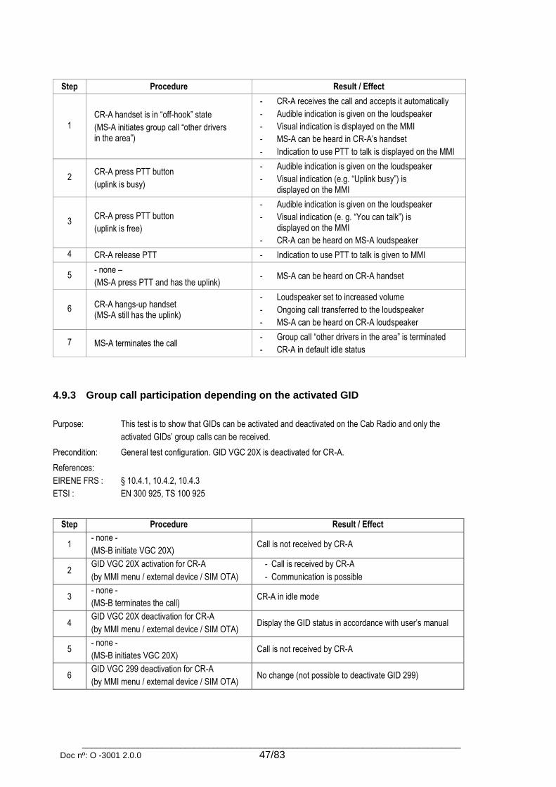
_________________________________________________________________________________
Doc nº: O -3001 2.0.0 47/83
Step Procedure Result / Effect
1 CR-A handset is in “off-hook” state
(MS-A initiates group call “other drivers in the area”)
- CR-A receives the call and accepts it automatically
- Audible indication is given on the loudspeaker
- Visual indication is displayed on the MMI
- MS-A can be heard in CR-A’s handset
- Indication to use PTT to talk is displayed on the MMI
2 CR-A press PTT button
(uplink is busy)
- Audible indication is given on the loudspeaker
- Visual indication (e.g. “Uplink busy”) is displayed on the MMI
3 CR-A press PTT button
(uplink is free)
- Audible indication is given on the loudspeaker
- Visual indication (e. g. “You can talk”) is displayed on the MMI
- CR-A can be heard on MS-A loudspeaker
4 CR-A release PTT - Indication to use PTT to talk is given to MMI
5 - none –
(MS-A press PTT and has the uplink) - MS-A can be heard on CR-A handset
6 CR-A hangs-up handset (MS-A still has the uplink)
- Loudspeaker set to increased volume
- Ongoing call transferred to the loudspeaker
- MS-A can be heard on CR-A loudspeaker
7 MS-A terminates the call - Group call “other drivers in the area” is terminated
- CR-A in default idle status
4.9.3 Group call participation depending on the activated GID
Purpose: This test is to show that GIDs can be activated and deactivated on the Cab Radio and only the
activated GIDs’ group calls can be received.
Precondition: General test configuration. GID VGC 20X is deactivated for CR-A.
References:
EIRENE FRS :
ETSI :
§ 10.4.1, 10.4.2, 10.4.3
EN 300 925, TS 100 925
Step Procedure Result / Effect
1 - none -
(MS-B initiate VGC 20X) Call is not received by CR-A
2 GID VGC 20X activation for CR-A
(by MMI menu / external device / SIM OTA)
- Call is received by CR-A
- Communication is possible
3 - none -
(MS-B terminates the call) CR-A in idle mode
4 GID VGC 20X deactivation for CR-A
(by MMI menu / external device / SIM OTA) Display the GID status in accordance with user’s manual
5 - none -
(MS-B initiates VGC 20X) Call is not received by CR-A
6 GID VGC 299 deactivation for CR-A
(by MMI menu / external device / SIM OTA) No change (not possible to deactivate GID 299)

_________________________________________________________________________________
Doc nº: O -3001 2.0.0 48/83
4.9.4 Outgoing voice group call
Purpose: This test is to show that a voice group call can be initiated by the Cab Radio.
Precondition: General test configuration. Additional VGC GIDs (e.g. 203) are activated on CR-A and MS-A.
References:
EIRENE FRS :
EIRENE SRS :
ETSI :
MORANE :
§ 4.2.1, 5.2.3.39, 11.2.3.2
§ 5.5.4, 5.5.14, 5.5.15
EN 300 925, TS 100 925, TS 100 932, TS 100 933, TS 127 007, TS 103 169
F 10 T 6001
Step Procedure Result / Effect
1
CR-A initiates a voice group call by
entering phone number or
using dedicated menu selection
(e.g. VGC 203, not VGC 200 or VGC 299)
- MS-A receives the call
- VGC established with eMLPP <4>.
- Audible indication is given on the loudspeaker
- Visual indication is displayed on the MMI
- Indication to use PTT to talk is displayed on the MMI
- Incoming audio is connected to the loudspeaker until the driver picks up the handset
2 CR-A pick up handset and press PTT
- Loudspeaker set to reduced volume
- Communication is activated on the handset
- CR-A has a dedicated uplink until the PTT button is released or the network timer expires
- CR-A can be heard on MS-A loudspeaker
3 CR-A release PTT - Indication to use PTT to talk is displayed on the MMI
4 CR-A press PTT button
(uplink is busy)
- Audible indication is given on the loudspeaker
- Visual indication (e.g. “Uplink busy”) is displayed on the MMI
5 CR-A press PTT button
(uplink is free)
- Audible indication is given on the loudspeaker
- Visual indication (e. g. “You can talk”) is displayed on the MMI
- CR-A can be heard on MS-A loudspeaker
6 CR-A release PTT - Indication to use PTT to talk is displayed on the MMI
7 CR-A terminates group call - Call terminated
- CR-A in default idle status
4.9.5 Outgoing voice group call – “other drivers in the area”
Purpose: This test is to show that the group call “other drivers in the area” is initiated and managed by the Cab
Radio. The call established with eMLPP <2>.
Precondition: General test configuration. MS-A and CR-A are in the same group call area.
References:
EIRENE FRS :
EIRENE SRS :
ETSI :
MORANE :
§ 4.2.1, 5.2.2iv, 5.2.2.9, 5.2.2.10, 5.2.2.12, 5.2.2.13, 5.2.2.14, 5.2.2.15, 5.2.2.48, 5.2.2.54, 5.2.2.60,
5.2.4.9, 10.2.1, 10.2.2
§ 4.3.1, 5.3.3, 5.3.4, 5.5.6, 10.2.1
EN 300 925, TS 100 925, TS 100 932, TS 100 933, TS 100 948, TS 103 169
F 10 T 6001

_________________________________________________________________________________
Doc nº: O -3001 2.0.0 49/83
Step Procedure Effects
1 CR-A initiates group call “other drivers in area” using dedicated MMI menu selection
- MS-A receives the call
- VGC established with eMLPP <2>
- Audible indication is given on the loudspeaker
- Visual indication is displayed on the MMI
- Indication to use PTT to talk is displayed on the MMI
- Incoming audio is connected to the loudspeaker until the driver picks up the handset
2 - none -
On the Controller’s display:
GID, GCA, call type and Functional umber of CR-A (displayed information are based on the transmitted UUS1 OTDI from CR-A during VGC establishment)
3 CR-A pick up handset and press PTT
- Loudspeaker set to reduced volume
- Communication is activated on the handset
- CR-A has a dedicated uplink until the PTT button is released or the network timer expires
- CR-A can be heard on MS-A loudspeaker
4 CR-A release PTT - Indication to use PTT to talk is given to MMI
5 CR-A press PTT button
(uplink is busy)
- Audible indication is given on the loudspeaker
- Visual indication (e.g. “Uplink busy”) is displayed on the MMI
6 CR-A press PTT button
(uplink is free)
- Audible indication is given on the loudspeaker
- Visual indication (e. g. “You can talk”) is displayed on the MMI
- CR-A can be heard on MS-A loudspeaker
7 CR-A release PTT - Indication to use PTT to talk is given to MMI
8 CR-A terminates group call - Group call “other drivers in area” is terminated
- CR-A in default idle status
4.9.6 Visualisation – "Unable to establish VGC"
Purpose: This test is to show that the failure of a group call establishment is indicated audio-visually.
Precondition: General test configuration. VGC 20X barred in the network
References:
EIRENE FRS :
§ 5.2.2.17
Step Procedure Result / Effect
1 CR-A initiates a VGC 20X.
(call establishment barred in the network)
- CR-A displays the outgoing VGC 20X on the MMI
- Failure of the call establishment indicated audio-visually
- CR-A in idle mode

_________________________________________________________________________________
Doc nº: O -3001 2.0.0 50/83
4.9.7 Leaving voice group call
Purpose: This test is to show that the Cab Radio can leave an ongoing voice group call without terminating
it.
Precondition: General test configuration
References:
EIRENE FRS :
ETSI :
§ 5.2.2.61
TS 100 933
Step Procedure Result / Effect
1 - none -
(MS-B initiates VGC 20X) CR-A receives group call and joins automatically
2 CR-A leaves the ongoing VGC
- VGC is left without being terminated,
- CR-A in idle mode
- VGC 20X continues to exist on MS-B
3 - none -
(MS-B terminates VGC 20X)
- VGC 20X terminated
- CR-A still in idle mode
4.9.8 Terminating voice group call – “other drivers in the area”
Purpose: This test is to show that the group call initiated by the Cab Radio can be exited when the uplink is
occupied. The group call stays connected between the other participants and re-entry for the Cab
Radio (initiator) is possible.
Precondition: General test configuration. MS-A and CR-A are in the same group call area.
References:
EIRENE FRS :
EIRENE SRS :
ETSI :
§ 4.2.1, 5.2.2.15, 5.2.2.61
§ 4.3.1, 5.5.24
TS 100 933
Step Procedure Result / Effect
1 CR-A initiates group call “other drivers in the area”
MS-A receives group call
2 - none - (MS-A takes the uplink by pressing PTT)
MS-A can be heard on CR-A
3 CR-A tries to terminate group call Group call “other drivers in area” cannot be terminated (uplink occupied by MS-A)
4 CR-A leaves group call automatically after the termination attempt or manually by another MMI action
- Group call continues without CR-A
- CR-A in default idle status
5 CR-A initiates group call “other drivers in the area”
- CR-A rejoins ongoing group call “other drivers in area”
- Audible indication is given on the loudspeaker
- Visual indication with group identity is displayed
6 (MS-A release PTT - uplink free)
CR-A press PTT button
- Audible indication is given on the loudspeaker
- Visual indication (e. g. “Talk”) is displayed on the MMI
- CR-A can be heard on MS-A loudspeaker
7 CR-A terminates group call - Group call “other drivers in area” is terminated
- CR-A in default idle status

_________________________________________________________________________________
Doc nº: O -3001 2.0.0 51/83
4.9.9 Moving out of the group call area
Purpose: This test is to show that when the Cab Radio is in an ongoing group call and it leaves the group call
area the group call is also left.
Precondition: General test configuration. CR-A first in train mode and later in shunting mode.
References:
EIRENE FRS :
§ 4.2.3, 5.2.2.16, 5.2.2.55
Step Procedure Result / Effect
1a CR-A initiates group call GID 200 / GID 500 - Group call established
- MS-A receives and joins group call
1b - none –
(MS-A initiates group call GID 200 / GID 500)
- Group call established
- CR-A receives group call and joins call automatically
2
- none –
(change the attenuation at the handover machine to initiate cell change and group call area change for CR-A)
- CR-A’s group call area changed
- CR-A leaves ongoing group call
- Audible indication is given on the loudspeaker
- Visual indication is displayed on the MMI
- CR-A in default idle status
4.10 Conference calls
4.10.1 Multiparty call (MPTY)
Purpose: This test is to show that a general multiparty call can be established and is handled correctly by the
Cab Radio.
Precondition: General test configuration. CR-A, MS-A and MS-B has different registered train numbers.
References:
EIRENE FRS :
EIRENE SRS :
ETSI :
§ 4.2.1
§ 4.3.3, 5.5.19
EN 300 918, EN 301 702, TS 122 087, TS 124 080
Step Procedure Result / Effect
1 CR-A initiates a PTP call to MS-A PTP call to MS-A established
2 CR-A creates a multiparty call with MS-A and MS-B
- CR-A initiate a PTP call to MS-B
- Multiparty call created between CR-A, MS-A and MS-B
- Visual indication (e.g. “Multiparty call” ) is displayed on the MMI
- Communication is possible for every participant
3 - none –
(MS-A leaves the call)
- CR-A is notified of MS-A leaving the call (optional)
- Call continues.
4 CR-A terminates the call - Ongoing multiparty call terminated.
- CR-A in default idle status
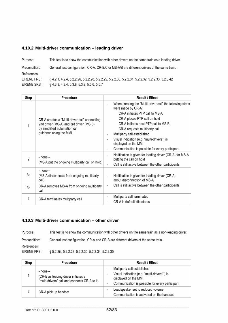
_________________________________________________________________________________
Doc nº: O -3001 2.0.0 52/83
4.10.2 Multi-driver communication – leading driver
Purpose: This test is to show the communication with other drivers on the same train as a leading driver.
Precondition: General test configuration. CR-A, CR-B/C or MS-A/B are different drivers of the same train.
References:
EIRENE FRS :
EIRENE SRS :
§ 4.2.1, 4.2.4, 5.2.2.26, 5.2.2.28, 5.2.2.29, 5.2.2.30, 5.2.2.31, 5.2.2.32, 5.2.2.33, 5.2.3.42
§ 4.3.3, 4.3.4, 5.3.8, 5.3.9, 5.5.6, 5.5.7
Step Procedure Result / Effect
1
CR-A creates a "Multi-driver call" connecting 2nd driver (MS-A) and 3rd driver (MS-B) by simplified automation or guidance using the MMI
- When creating the "Multi-driver call" the following steps were made by CR-A:
CR-A initiates PTP call to MS-A
CR-A places PTP call on hold
CR-A initiates next PTP call to MS-B
CR-A requests multiparty call
- Multiparty call established
- Visual indication (e.g. “multi-drivers”) is displayed on the MMI
- Communication is possible for every participant
2 - none –
(MS-A put the ongoing multiparty call on hold)
- Notification is given for leading driver (CR-A) for MS-A putting the call on hold
- Call is still active between the other participants
3a - none –
(MS-A disconnects from ongoing multiparty call)
- Notification is given for leading driver (CR-A) about disconnection of MS-A
- Call is still active between the other participants 3b CR-A removes MS-A from ongoing multiparty
call
4 CR-A terminates multiparty call - Multiparty call terminated
- CR-A in default idle status
4.10.3 Multi-driver communication – other driver
Purpose: This test is to show the communication with other drivers on the same train as a non-leading driver.
Precondition: General test configuration. CR-A and CR-B are different drivers of the same train.
References:
EIRENE FRS :
§ 5.2.2iii, 5.2.2.28, 5.2.2.30, 5.2.2.34, 5.2.2.35
Step Procedure Result / Effect
1 - none –
(CR-B as leading driver initiates a “multi-drivers” call and connects CR-A to it)
- Multiparty call established
- Visual indication (e.g. “multi-drivers” ) is displayed on the MMI
- Communication is possible for every participant
2 CR-A pick up handset - Loudspeaker set to reduced volume
- Communication is activated on the handset
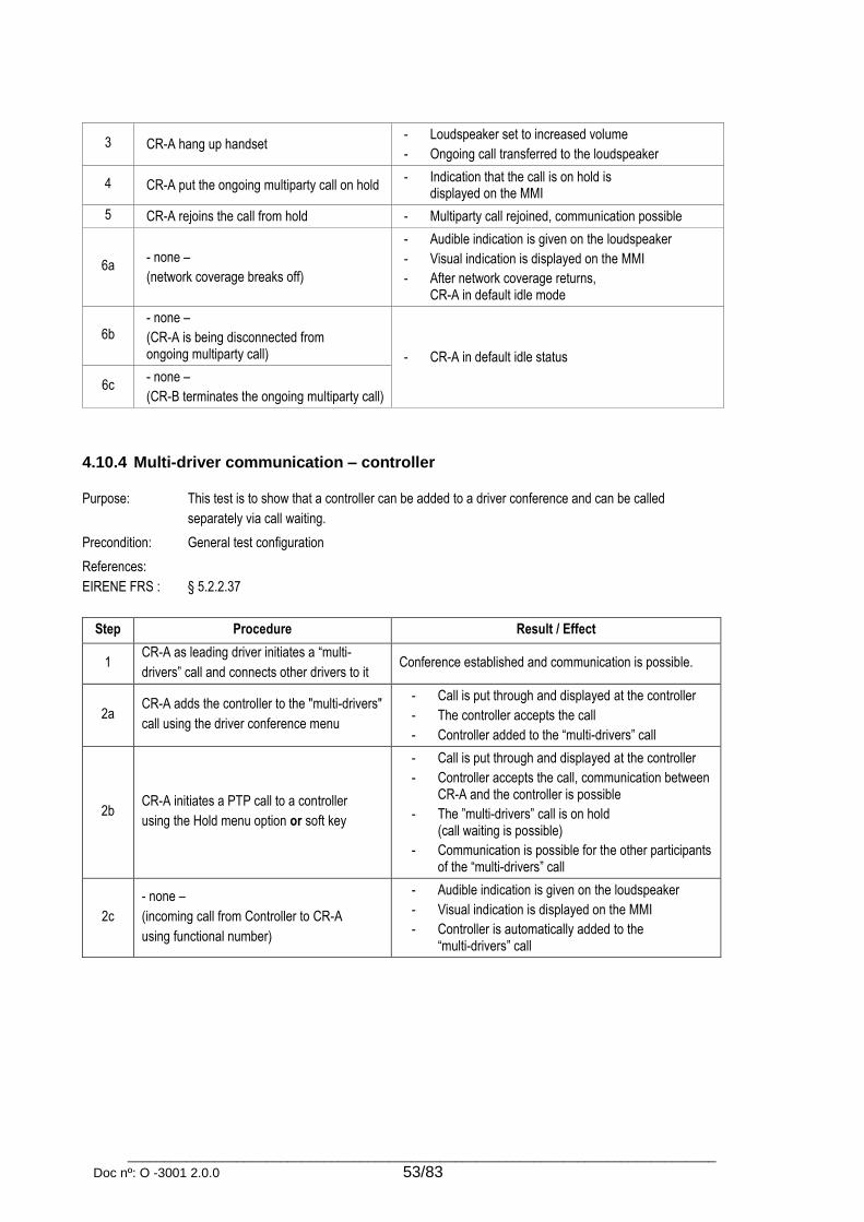
_________________________________________________________________________________
Doc nº: O -3001 2.0.0 53/83
3 CR-A hang up handset - Loudspeaker set to increased volume
- Ongoing call transferred to the loudspeaker
4 CR-A put the ongoing multiparty call on hold - Indication that the call is on hold is
displayed on the MMI
5 CR-A rejoins the call from hold - Multiparty call rejoined, communication possible
6a - none –
(network coverage breaks off)
- Audible indication is given on the loudspeaker
- Visual indication is displayed on the MMI
- After network coverage returns, CR-A in default idle mode
6b - none –
(CR-A is being disconnected from ongoing multiparty call) - CR-A in default idle status
6c - none –
(CR-B terminates the ongoing multiparty call)
4.10.4 Multi-driver communication – controller
Purpose: This test is to show that a controller can be added to a driver conference and can be called
separately via call waiting.
Precondition: General test configuration
References:
EIRENE FRS :
§ 5.2.2.37
Step Procedure Result / Effect
1 CR-A as leading driver initiates a “multi-
drivers” call and connects other drivers to it Conference established and communication is possible.
2a CR-A adds the controller to the "multi-drivers"
call using the driver conference menu
- Call is put through and displayed at the controller
- The controller accepts the call
- Controller added to the “multi-drivers” call
2b CR-A initiates a PTP call to a controller
using the Hold menu option or soft key
- Call is put through and displayed at the controller
- Controller accepts the call, communication between CR-A and the controller is possible
- The ”multi-drivers” call is on hold (call waiting is possible)
- Communication is possible for the other participants of the “multi-drivers” call
2c
- none –
(incoming call from Controller to CR-A
using functional number)
- Audible indication is given on the loudspeaker
- Visual indication is displayed on the MMI
- Controller is automatically added to the “multi-drivers” call

_________________________________________________________________________________
Doc nº: O -3001 2.0.0 54/83
4.11 Call arbitration
4.11.1 Call arbitration – ongoing railway emergency call
Purpose:
Note:
This test is to show the call arbitration with an ongoing emergency call.
Intercom / Public Address / Chief Conductor (with UIC Intercom link) has no eMLPP but has priorities
according to EIRENE SRS §5A.1
Precondition: General test configuration;
CR-A is in an ongoing railway emergency call
(eMLPP <0> , GID 299 , GID 599)
References:
EIRENE SRS :
ETSI :
§ 5.5.20, 5.5.21, 5A.1
TS 100 932
Step Procedure Result / Effect
New outgoing calls
1a Emergency call from CR-A
(eMLPP <0>) - No change (only displayed to the controller)
1b Call to the Intercom from CR-A - Intercom connected to the handset
- Emergency call transferred to the loudspeaker
1c Call to the Public Address from CR-A - Public Address connected to the handset
- Emergency call transferred to the loudspeaker
1d Call to the Chief Conductor from CR-A - Emergency call maintained
- New call sent by UIC Intercom link (or no change if no UIC Intercom link present)
New incoming calls
1e Other incoming call
(eMLPP <4>)
- Emergency call maintained
- Incoming call indicated but cannot be accepted
4.11.2 Call arbitration – ongoing high priority group call between drivers in the same area
Purpose:
Note:
This test is to show the call arbitration with an ongoing high priority group call between
drivers in the same area.
Intercom / Public Address / Chief Conductor (with UIC Intercom link) has no eMLPP but has
priorities according to EIRENE SRS §5A.1
Precondition: General test configuration;
CR-A is in an ongoing high priority group call between drivers in the same area
(eMLPP <2> , GID 200)
References:
EIRENE FRS :
EIRENE SRS :
ETSI :
§ 10.2.3
§ 5.5.20, 5.5.21, 5A.1
TS 100 932, TS 103 169

_________________________________________________________________________________
Doc nº: O -3001 2.0.0 55/83
Step Procedure Result / Effect
New outgoing calls
1a Emergency call from CR-A
(eMLPP <0>)
- On-going call left
- Emergency call established
1b Call to the Intercom from CR-A - Intercom connected to the handset
- High priority group call transferred to the loudspeaker
1c Call to the Public Address from CR-A - Public Address connected to the handset
- High priority group call transferred to the loudspeaker
1d Call to the Chief Conductor from CR-A - Call sent by UIC Intercom link (or no change if no UIC Intercom link present)
New incoming calls
1e Emergency call (eMLPP <0>) - On-going call left
- Emergency call connected
1f Other incoming call
(eMLPP <4>)
- On-going call maintained
- Incoming call clearly indicated.
4.11.3 Call arbitration – ongoing operational group call to drivers in the same area
Purpose:
Note:
This test is to show the call arbitration with an ongoing operational group call to drivers in the
same area .
Intercom / Public Address / Chief Conductor (with UIC Intercom link) has no eMLPP but has
priorities according to EIRENE SRS §5A.1
Precondition: General test configuration;
CR-A is in an ongoing operational group call to drivers in the same area
(eMLPP <3> , GID 555)
References:
EIRENE FRS :
EIRENE SRS :
ETSI :
§ 10.2.3
§ 5.5.20, 5.5.21, 5A.1
TS 100 932
Step Procedure Result / Effect
New outgoing calls
1a Emergency call from CR-A
(eMLPP <0>)
- On-going call left
- Emergency call established
1b Call to the Intercom from CR-A - Intercom connected to the handset
- Operational group call transferred to the loudspeaker
1c Call to the Public Address from CR-A - Public Address connected to the handset
- Operational group call transferred to the loudspeaker
1d Call to the Chief Conductor from CR-A - Call sent by UIC Intercom link (or no change if no UIC Intercom link present)

_________________________________________________________________________________
Doc nº: O -3001 2.0.0 56/83
New incoming calls
1e Emergency call (eMLPP <0>) - On-going call left
- Emergency call connected
1f High priority group call between drivers
in the same area (eMLPP <2>) (GID 200)
- On-going call left
- Incoming call established
1g Other incoming call
(eMLPP <4>)
- On-going call maintained
- Incoming call clearly indicated
4.11.4 Call arbitration – ongoing call from a controller
Purpose:
Note:
This test is to show the call arbitration with an ongoing call from a controller (or operational calls).
Intercom / Public Address / Chief Conductor (with UIC Intercom link) has no eMLPP but has
priorities according to EIRENE SRS §5A.1
Precondition: General test configuration;
CR-A is in an ongoing call from a controller
(eMLPP <3>)
References:
EIRENE FRS :
EIRENE SRS :
ETSI :
§ 10.2.3
§ 5.5.20, 5.5.21, 5A.1
TS 100 932
Step Procedure Result / Effect
New outgoing calls
1a Emergency call from CR-A
(eMLPP <0>)
- On-going call left
- Emergency call established
1b Call to the Intercom from CR-A - On-going call left
- Intercom connected
1c Call to the Public Address from CR-A - On-going call left
- Public Address connected
1d Call to the Chief Conductor from CR-A - Call sent by UIC Intercom link (or no change if no UIC Intercom link present)
1e Other call from CR-A
(eMLPP <4>)
- New call connected
- On-going call put on hold
New incoming calls
1f Emergency call from controller
(eMLPP <0>)
- On-going call left
- Emergency call established
1g High priority group call between drivers
in the same area (eMLPP <2>) (GID 200)
- On-going call left
- Incoming call established
1h Operational group call to drivers in the same
area (eMLPP<3>) (GID 555) - On-going call maintained
- Incoming call indicated 1i
Other incoming call
(eMLPP <4>)

_________________________________________________________________________________
Doc nº: O -3001 2.0.0 57/83
4.11.5 Call arbitration – ongoing “other drivers on same train” call
Purpose:
Note:
This test is to show the call arbitration with an ongoing “other drivers on same train” call.
Intercom / Public Address / Chief Conductor (with UIC Intercom link) has no eMLPP but has
priorities according to EIRENE SRS §5A.1
Precondition: General test configuration;
CR-A is in an ongoing “other drivers on same train” call as leading driver
(Multi-driver call with eMLPP <3>)
References:
EIRENE FRS :
EIRENE SRS :
ETSI :
§ 10.2.3
§ 5.5.20, 5.5.21, 5A.1
TS 100 932
Step Procedure Result / Effect
New outgoing calls
1a Emergency call from CR-A
(eMLPP <0>)
- On-going call left
- Emergency call established (Leading driver may re-establish call to non leading drivers at the end of emergency call)
1b Call to the Intercom from CR-A - Intercom connected to the handset
- “Other drivers on same train” call transferred to the loudspeaker
1c Call to the Public Address from CR-A - Public Address connected to the handset
- “Other drivers on same train” call transferred to the loudspeaker
1d Call to the Chief Conductor from CR-A - Call sent by UIC Intercom link (or no change if no UIC Intercom link present)
1e Call to the Controller from CR-A
(eMLPP <3>)
- Call connected (Multi-driver communications placed on hold or driver may add controller to the multi-driver communication)
1f Other call from CR-A
(eMLPP <4>)
- Multi-driver communication is on hold
- New call connected
New incoming calls
1g Emergency call from controller
(eMLPP <0>)
- On-going call left
- Emergency call established
1h High priority group call between drivers
in the same area (eMLPP <2>) (GID 200)
- On-going call left
- Incoming call established
1i Other incoming calls from controller (eMLPP <3>)
- On-going call is maintained
- Controller is added to the ongoing call
1j Operational group call to drivers in the same
area (eMLPP<3>) (GID 555) - On-going call is maintained
- Incoming call is clearly indicated 1k
Other incoming call
(eMLPP <4>)
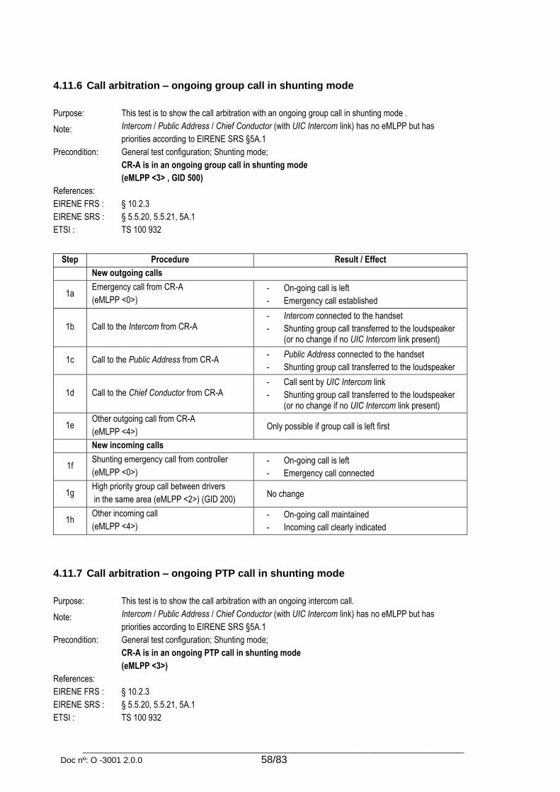
_________________________________________________________________________________
Doc nº: O -3001 2.0.0 58/83
4.11.6 Call arbitration – ongoing group call in shunting mode
Purpose:
Note:
This test is to show the call arbitration with an ongoing group call in shunting mode .
Intercom / Public Address / Chief Conductor (with UIC Intercom link) has no eMLPP but has
priorities according to EIRENE SRS §5A.1
Precondition: General test configuration; Shunting mode;
CR-A is in an ongoing group call in shunting mode
(eMLPP <3> , GID 500)
References:
EIRENE FRS :
EIRENE SRS :
ETSI :
§ 10.2.3
§ 5.5.20, 5.5.21, 5A.1
TS 100 932
Step Procedure Result / Effect
New outgoing calls
1a Emergency call from CR-A
(eMLPP <0>)
- On-going call is left
- Emergency call established
1b Call to the Intercom from CR-A - Intercom connected to the handset
- Shunting group call transferred to the loudspeaker (or no change if no UIC Intercom link present)
1c Call to the Public Address from CR-A - Public Address connected to the handset
- Shunting group call transferred to the loudspeaker
1d Call to the Chief Conductor from CR-A - Call sent by UIC Intercom link
- Shunting group call transferred to the loudspeaker (or no change if no UIC Intercom link present)
1e Other outgoing call from CR-A
(eMLPP <4>) Only possible if group call is left first
New incoming calls
1f Shunting emergency call from controller
(eMLPP <0>)
- On-going call is left
- Emergency call connected
1g High priority group call between drivers
in the same area (eMLPP <2>) (GID 200) No change
1h Other incoming call
(eMLPP <4>)
- On-going call maintained
- Incoming call clearly indicated
4.11.7 Call arbitration – ongoing PTP call in shunting mode
Purpose:
Note:
This test is to show the call arbitration with an ongoing intercom call.
Intercom / Public Address / Chief Conductor (with UIC Intercom link) has no eMLPP but has
priorities according to EIRENE SRS §5A.1
Precondition: General test configuration; Shunting mode;
CR-A is in an ongoing PTP call in shunting mode
(eMLPP <3>)
References:
EIRENE FRS :
EIRENE SRS :
ETSI :
§ 10.2.3
§ 5.5.20, 5.5.21, 5A.1
TS 100 932

_________________________________________________________________________________
Doc nº: O -3001 2.0.0 59/83
Step Procedure Result / Effect
New outgoing calls
1a Emergency call from CR-A
(eMLPP <0>)
- On-going call left
- Emergency call established
1b Call to the Intercom from CR-A - Intercom connected to the handset
- PTP call transferred to the loudspeaker (or no change if no UIC Intercom link present)
1c Call to the Public Address from CR-A - Public Address connected to the handset
- PTP call transferred to the loudspeaker
1d Call to the Chief Conductor from CR-A - Call sent by UIC Intercom link
- PTP call transferred to the loudspeaker (or no change if no UIC Intercom link present)
1e Other outgoing call from CR-A
(eMLPP <4>)
- On-going call is on hold
- New call connected
New incoming calls
1f Shunting emergency call from controller
(eMLPP <0>)
- On-going call left
- Emergency call connected
1g High priority group call between drivers
in the same area (eMLPP <2>) (GID 200) No change
1h Other incoming call
(eMLPP <4>)
- On-going call maintained
- Incoming call is clearly indicated
4.12 Railway emergency calls
4.12.1 Incoming railway emergency call
Purpose: This test is to show that when the Cab Radio receives an incoming railway emergency call
automatically joins the call.
Precondition: General test configuration; CR-A and MS-A in Train Mode and later in Shunting Mode.
References:
EIRENE FRS :
EIRENE SRS :
ETSI :
§ 4.2.4, 5.2.2iii, 5.2.2.56, 5.2.2.60, 10.4.5, 13.1.6, 13.2.4.1, 13.3.1
§ 4.3.1, 4.3.4, 5.5.4, 5.5.19, 13.4.1, 13.4.2
TS 103 169
Step Procedure Result / Effect
1 - none -
(MS-A initiates „railway emergency call”)
- CR-A receives and joins call automatically
- Audible indication is given on the
loudspeaker for 5 seconds
- Visual indication is displayed on the MMI
including group identity
(299/599 or textual translation)
- Caller can be heard on the loudspeaker
- Indication to use PTT to talk is displayed on the MMI
2 CR-A pick up handset - Loudspeaker set to reduced volume
- Communication is activated on the handset

_________________________________________________________________________________
Doc nº: O -3001 2.0.0 60/83
3 CR-A hangs-up handset
- Loudspeaker set to increased volume
- Ongoing call transferred to the loudspeaker
- MS-A can be heard on CR-A loudspeaker
4 CR-A tries to leave or terminate the railway emergency call
- CR-A cannot leave or terminate the „railway
emergency call”
5 - none -
(MS-A terminates emergency call)
- Emergency call terminated
- CR-A in default idle status
4.12.2 Outgoing railway emergency call
Purpose: This test is to show that a railway emergency call is initiated and managed by the Cab Radio using
emergency access and that this established with eMLPP <0> (railway emergency). The functional
number of the Cab Radio is transmitted to the controller when sending a train emergency call.
Precondition: General test configuration. CR-A in Train Mode and later in Shunting Mode.
References:
EIRENE FRS :
EIRENE SRS :
ETSI :
MORANE :
§ 4.2.4, 5.2.2iii, 5.2.2.18, 5.2.2.20, 5.2.2.21, 5.2.2.22, 5.2.2.24, 5.2.2.60, 5.2.4.9, 9.3.2, 10.2.1,
10.2.2, 13.1.4, 13.1.5, 13.1.6, 13.2.2.1, 13.2.2.2, 13.2.2.4, 13.2.2.6, 13.2.3.1, 13.2.3.3, 13.2.4.1
§ 4.3.4, 4.4.3, 5.3.5, 5.3.6, 5.5.4, 5.5.5, 10.2.1, 13.2.2, 13.3.1
EN 300 925, TS 100 905, TS 100 933
F 10 T 6001
Step Procedure Result / Effect
1a CR-A initiates „railway emergency call” using “Emergency button”
(handset is off-hook)
- Dialling or status indication for dialling
starts within 2 seconds
- An attention sound with reduced volume is in the
loudspeaker for 5 seconds while the call is initiated
1b CR-A initiates „railway emergency call” using “Emergency button”
(handset is on-hook)
- Dialling or status indication for dialling starts within 2 seconds
- An attention sound with increased volume is in the
loudspeaker for 5 seconds while the call is initiated
2 - none -
- Permanent visual indication is displayed on the MMI;
- Emergency call established with eMLPP <0>
- GID, GCA, Call Type (and FN of CR-A)
is displayed at the controller
- Indication to use PTT to talk is displayed on the MMI
3
(pick up handset if it is on-hook)
CR-A press PTT button
(uplink is free)
- Audible indication is given on the loudspeaker
- Visual indication (e. g. “You can talk”) is
- displayed on the MMI
- CR-A has a dedicated uplink until the PTT button is
released or the network timer expires
- CR-A can be heard on MS-A loudspeaker
4 Release PTT on CR-A
- Audible indication is given on the loudspeaker
- Indication to use PTT to talk is given to the driver on the MMI
5 CR-A hangs-up handset
- Loudspeaker set to increased volume
- Ongoing call transferred to the loudspeaker
- MS-A can be heard on CR-A loudspeaker

_________________________________________________________________________________
Doc nº: O -3001 2.0.0 61/83
6a CR-A terminates emergency call
- Emergency call terminated
- Visual indication - regarding the call - cleared
- CR-A in default idle status
6b - none –
(Controller terminates emergency call)
6c - none –
(network terminates the call after predefined time of no speech)
4.12.3 Railway emergency call – during ongoing call
Purpose: This test is to show that the Cab Radio participating in an ongoing non-emergency call can initiate a
“railway emergency call”.
Precondition: General test configuration. CR-A is in an ongoing PTP/group call with other participant(s)
References:
EIRENE FRS :
§ 5.2.4.7, 10.2.3
Step Procedure Result / Effect
1a (CR-A is in an ongoing PTP call)
CR-A initiates “railway emergency call”
- Ongoing PTP call is terminated
- Emergency call is established.
1b (CR-A is in an ongoing voice group call)
CR-A initiates “railway emergency call”
- Ongoing group call is left or terminated
- Emergency call is established.
4.12.4 Railway emergency call – leaving group call area
Purpose: This test is to show that the Cab Radio leaves the “railway emergency call” after moving out of the
group call area.
Precondition: General test configuration.
References:
EIRENE FRS :
ETSI :
§ 5.2.2.23, 13.2.4.2
TS 100 933
Step Procedure Result / Effect
1a - none –
(MS-A initiates “railway emergency call”) CR-A receives and joins the call automatically
1b CR-A initiates “railway emergency call” MS-A receives and joins the call automatically
2
- none –
(change of attenuation at the handover machine to initiate a cell change that invokes group call area change for CR-A)
- CR-A leaves emergency call
- Audible indication is given on the loudspeaker
- Visual indication is displayed on the MMI
- CR-A returns in default idle status
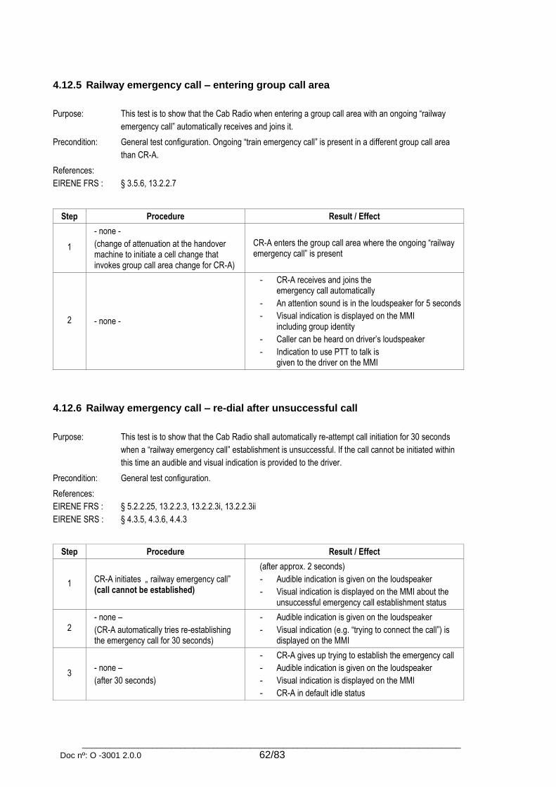
_________________________________________________________________________________
Doc nº: O -3001 2.0.0 62/83
4.12.5 Railway emergency call – entering group call area
Purpose: This test is to show that the Cab Radio when entering a group call area with an ongoing “railway
emergency call” automatically receives and joins it.
Precondition: General test configuration. Ongoing “train emergency call” is present in a different group call area
than CR-A.
References:
EIRENE FRS :
§ 3.5.6, 13.2.2.7
Step Procedure Result / Effect
1
- none -
(change of attenuation at the handover machine to initiate a cell change that invokes group call area change for CR-A)
CR-A enters the group call area where the ongoing “railway emergency call” is present
2 - none -
- CR-A receives and joins the emergency call automatically
- An attention sound is in the loudspeaker for 5 seconds
- Visual indication is displayed on the MMI including group identity
- Caller can be heard on driver’s loudspeaker
- Indication to use PTT to talk is given to the driver on the MMI
4.12.6 Railway emergency call – re-dial after unsuccessful call
Purpose: This test is to show that the Cab Radio shall automatically re-attempt call initiation for 30 seconds
when a “railway emergency call” establishment is unsuccessful. If the call cannot be initiated within
this time an audible and visual indication is provided to the driver.
Precondition: General test configuration.
References:
EIRENE FRS :
EIRENE SRS :
§ 5.2.2.25, 13.2.2.3, 13.2.2.3i, 13.2.2.3ii
§ 4.3.5, 4.3.6, 4.4.3
Step Procedure Result / Effect
1 CR-A initiates „ railway emergency call” (call cannot be established)
(after approx. 2 seconds)
- Audible indication is given on the loudspeaker
- Visual indication is displayed on the MMI about the unsuccessful emergency call establishment status
2 - none –
(CR-A automatically tries re-establishing the emergency call for 30 seconds)
- Audible indication is given on the loudspeaker
- Visual indication (e.g. “trying to connect the call”) is displayed on the MMI
3 - none –
(after 30 seconds)
- CR-A gives up trying to establish the emergency call
- Audible indication is given on the loudspeaker
- Visual indication is displayed on the MMI
- CR-A in default idle status
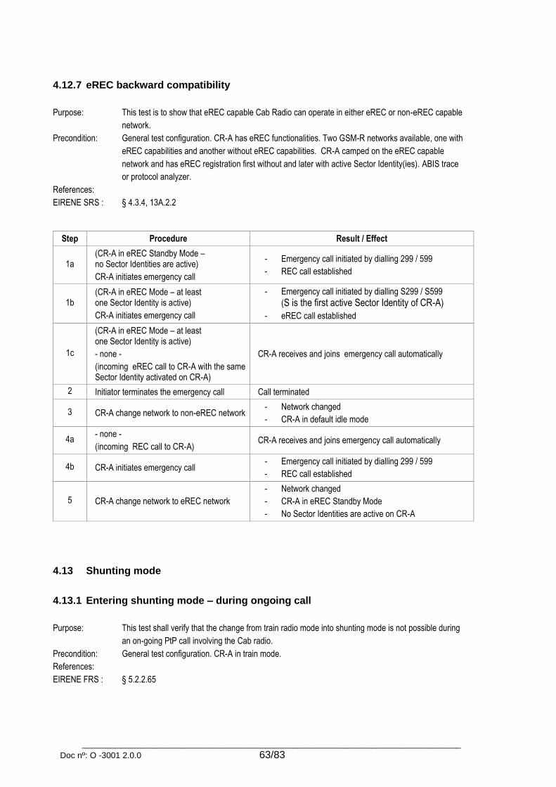
_________________________________________________________________________________
Doc nº: O -3001 2.0.0 63/83
4.12.7 eREC backward compatibility
Purpose: This test is to show that eREC capable Cab Radio can operate in either eREC or non-eREC capable
network.
Precondition: General test configuration. CR-A has eREC functionalities. Two GSM-R networks available, one with
eREC capabilities and another without eREC capabilities. CR-A camped on the eREC capable
network and has eREC registration first without and later with active Sector Identity(ies). ABIS trace
or protocol analyzer.
References:
EIRENE SRS :
§ 4.3.4, 13A.2.2
Step Procedure Result / Effect
1a (CR-A in eREC Standby Mode – no Sector Identities are active)
CR-A initiates emergency call
- Emergency call initiated by dialling 299 / 599
- REC call established
1b (CR-A in eREC Mode – at least one Sector Identity is active)
CR-A initiates emergency call
- Emergency call initiated by dialling S299 / S599
(S is the first active Sector Identity of CR-A)
- eREC call established
1c
(CR-A in eREC Mode – at least one Sector Identity is active)
- none -
(incoming eREC call to CR-A with the same Sector Identity activated on CR-A)
CR-A receives and joins emergency call automatically
2 Initiator terminates the emergency call Call terminated
3 CR-A change network to non-eREC network - Network changed
- CR-A in default idle mode
4a - none -
(incoming REC call to CR-A) CR-A receives and joins emergency call automatically
4b CR-A initiates emergency call - Emergency call initiated by dialling 299 / 599
- REC call established
5 CR-A change network to eREC network
- Network changed
- CR-A in eREC Standby Mode
- No Sector Identities are active on CR-A
4.13 Shunting mode
4.13.1 Entering shunting mode – during ongoing call
Purpose: This test shall verify that the change from train radio mode into shunting mode is not possible during
an on-going PtP call involving the Cab radio.
Precondition: General test configuration. CR-A in train mode.
References:
EIRENE FRS :
§ 5.2.2.65

_________________________________________________________________________________
Doc nº: O -3001 2.0.0 64/83
Step Procedure Result / Effect
1 (MS-A initiates a PTP call to CR-A)
CR-A accepts the call Call established, communication is possible
2 CR-A activates shunting mode using MMI menu (if available)
Activation of shunting mode not possible
CR-A maintains the ongoing call
4.13.2 Entering shunting mode – idle mode
Purpose: This test shall verify that the change from train radio mode into shunting mode is supported by the
Cab Radio.
Precondition: General test configuration. CR-A in train mode and has train number registered.
References:
EIRENE FRS :
EIRENE SRS :
ETSI :
§ 4.2.4, 13.1.7, 14.2.2
§ 4.3.4, 5.3.13, 14.4.1, 14.5.2
TS 127 007
Step Procedure Result / Effect
1 CR-A activates shunting mode using MMI menu
- CR-A performs the following steps during transition:
All active GIDs deactivated (except GID 299)
GID 599 activated
Emergency button assigned to GID 599
GID 299 deactivated
- Display is according to shunting mode (see user’s manual)
- CR-A in default idle status
2a - none –
(MS-A initiates PTP call to CR-A by FN) - CR does not receive the call (FN deregistered)
2b - none –
(MS-A initiates group call 200) - Group call GID 200/299 is established
- Group call is not received by CR- A
- CR-A in default idle status 2c - none –
(MS-A initiates train emergency call 299)
2d - none –
(MS-B initiates shunting group call 500) - CR-A receives and accepts the call automatically.
2e - none –
(MS-B initiates shunting emergency call)
4.13.3 Shunting registration
Purpose: This test is to show that the Cab Radio provides options for selecting shunting area and group
(and also role in dedicated shunting group) during shunting registration procedure.
Precondition: General test configuration. CR-A in shunting mode.
References:
EIRENE FRS :
EIRENE SRS :
MORANE :
§ 14.3.1
§ 11.3.5, 14.4.6, 14.5.2
E 10 T 6001

_________________________________________________________________________________
Doc nº: O -3001 2.0.0 65/83
Step Procedure Result / Effect
1 CR-A selects MMI menu for changing shunting registration
Shunting registration menu is displayed on the MMI
2 CR-A changes the shunting area and shunting group using MMI menu
- Only valid group ID (500-529) can be entered or selected from a list
3 CR-A changes the shunting role to driver, leader or team member using MMI menu
- Shunting role is changed
- CT6 registration carried out by USSD message
4 CR-A changes the shunting group to a dedicated group where ongoing shunting group call is present using MMI menu
- CR-A enters the selected shunting group
- New CT6 registration carried out
- CR-A automatically joins ongoing group call
5 CR-A leaves ongoing group call - Ongoing group call left
- CR-A in default idle status
6 CR-A changes the shunting area using MMI menu
- CR-A enters the selected shunting area
- New CT6 registration carried out
4.13.4 Shunting registration – failed registration
Purpose: This test is to show that a failed registration is indicated to the user.
Precondition: General test configuration. CR-A in shunting mode and in a defined group area with a registered
functional identity.
References:
EIRENE FRS :
EIRENE SRS :
§ 11.3.2.4i
§ 14.4.7
Step Procedure Result / Effect
1 CR-A selects MMI menu for changing shunting registration
Shunting registration menu is displayed on the MMI
2 CR-A changes call area and group number using MMI menu
- Automatic deregistration of the FN for group number is attempted (deregistration NOT successful)
- Indication is given to the user of the failure
4.13.5 Shunting group activation
Purpose: This test is to show that during shunting operation, besides the emergency group ID 599, only one
group ID can be activated.
Precondition: General test configuration. Shunting group ID 500, 50X are available;
References:
EIRENE SRS :
§ 14.4.9
Step Procedure Result / Effect
1
(CR registered to shunting GID 500)
CR-A changes to a dedicated shunting
group (GID 50X)
CR-A changes to dedicated shunting group 50X
2 – none –
(MS-A initiate a SGC in GID 500)
- Shunting group call established
- CR-A in default idle status

_________________________________________________________________________________
Doc nº: O -3001 2.0.0 66/83
3 – none –
(MS-A initiate a shunting emergency call)
- Shunting emergency call established
- CR-A joins the emergency call automatically
4.13.6 Shunting area change – joining ongoing shunting emergency call
Purpose: This test is to show that the Cab Radio joins an ongoing shunting emergency call automatically
when entering into an area with an ongoing shunting emergency call.
Precondition: General test configuration; CR-A in shunting mode;
References:
EIRENE FRS :
§ 13.2.2.7
Step Procedure Result / Effect
1
CR-A enters a shunting area with
an ongoing shunting emergency call
(GID 599)
- CR-A changes the area and joins the
ongoing call automatically
- Audible and visual indication of the call
- Initiator of the emergency can be heard on CR-A
4.13.7 Shunting area change – during shunting group call
Purpose: This test is to show that the Cab Radio leaves the shunting group call after moving out of the group
call area.
Precondition: General test configuration. CR-A in shunting mode.
References:
EIRENE FRS :
§ 5.2.2.55
Step Procedure Result / Effect
1 - none –
(MS-A initiates shunting group call 500) CR-A receives and accepts call automatically
2 Change of attenuation at the handover machine to initiate a cell change that invokes group call area change for CR-A
- Audible indication is given on the loudspeaker
- Visual indication is displayed on the MMI
- CR-A leaves ongoing group call
- Shunting group call remains ongoing for the other participants
4.13.8 Exiting shunting mode
Purpose: This test is to show that the Cab Radio can leave shunting radio mode and enter train radio mode.
Precondition: General test configuration; CR-A in shunting mode;
References:
EIRENE FRS :
EIRENE SRS :
§ 5.2.2.64
§ 14.4.15, 14.4.16, 14.4.18, 14.4.19, 14.4.20
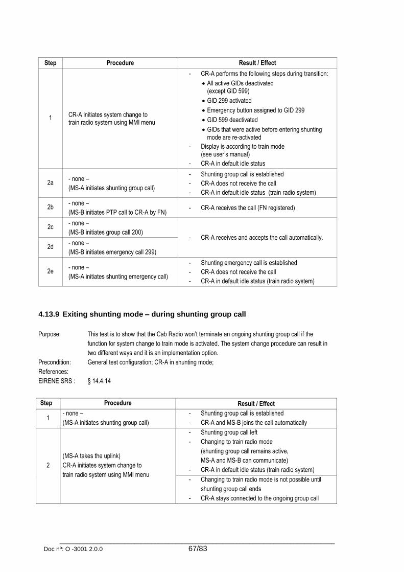
_________________________________________________________________________________
Doc nº: O -3001 2.0.0 67/83
Step Procedure Result / Effect
1 CR-A initiates system change to train radio system using MMI menu
- CR-A performs the following steps during transition:
All active GIDs deactivated (except GID 599)
GID 299 activated
Emergency button assigned to GID 299
GID 599 deactivated
GIDs that were active before entering shunting mode are re-activated
- Display is according to train mode (see user’s manual)
- CR-A in default idle status
2a - none –
(MS-A initiates shunting group call)
- Shunting group call is established
- CR-A does not receive the call
- CR-A in default idle status (train radio system)
2b - none –
(MS-B initiates PTP call to CR-A by FN) - CR-A receives the call (FN registered)
2c - none –
(MS-B initiates group call 200) - CR-A receives and accepts the call automatically.
2d - none –
(MS-B initiates emergency call 299)
2e - none –
(MS-A initiates shunting emergency call)
- Shunting emergency call is established
- CR-A does not receive the call
- CR-A in default idle status (train radio system)
4.13.9 Exiting shunting mode – during shunting group call
Purpose: This test is to show that the Cab Radio won’t terminate an ongoing shunting group call if the
function for system change to train mode is activated. The system change procedure can result in
two different ways and it is an implementation option.
Precondition: General test configuration; CR-A in shunting mode;
References:
EIRENE SRS :
§ 14.4.14
Step Procedure Result / Effect
1 - none –
(MS-A initiates shunting group call)
- Shunting group call is established
- CR-A and MS-B joins the call automatically
2
(MS-A takes the uplink)
CR-A initiates system change to
train radio system using MMI menu
- Shunting group call left
- Changing to train radio mode
(shunting group call remains active,
MS-A and MS-B can communicate)
- CR-A in default idle status (train radio system)
- Changing to train radio mode is not possible until
shunting group call ends
- CR-A stays connected to the ongoing group call

_________________________________________________________________________________
Doc nº: O -3001 2.0.0 68/83
4.13.10 Storage of shunting data
Purpose: This test is to show that shunting data is stored in non-volatile memory to be used for the start-up
procedure.
Precondition: General test configuration. CR-A in shunting mode and registered to a dedicated shunting group.
References:
EIRENE SRS :
§ 14.4.11
Step Procedure Result / Effect
1 Power off CR-A CR-A powered off
2 Power on CR-A
- CR-A performs its normal start-up
- CR-A is in default train idle status or in default idle status.
- Shunting data are the same as was before
4.13.11 Group call in shunting mode
Purpose: This test is to show that a voice group call can be initiated in shunting mode by the Cab Radio.
Precondition: General test configuration. Cab Radio and MS-A in shunting mode and registered to the same
dedicated shunting group.
References:
EIRENE FRS :
§ 5.2.2.9, 5.2.2.60
Step Procedure Result / Effect
1
CR-A initiates a voice group call by
entering phone number or
using dedicated menu selection or
by pressing PTT
- MS-A receives the call
- SGC established with eMLPP <3>.
- Audible indication is given on the loudspeaker
- Visual indication is displayed on the MMI
- Indication to use PTT to talk is displayed on the MMI
- Incoming audio is connected to the loudspeaker until the driver picks up the handset
2 CR-A pick up handset and press PTT
- Loudspeaker set to reduced volume
- Communication is activated on the handset
- CR-A has a dedicated uplink until the PTT button is released or the network timer expires
- CR-A can be heard on MS-A loudspeaker
3 CR-A release PTT - Audible indication is given on the loudspeaker
- Indication to use PTT to talk is displayed on the MMI
4 CR-A press PTT button
(uplink is busy)
- Audible indication is given on the loudspeaker
- Visual indication (e.g. “Uplink busy”) is displayed on the MMI
5 CR-A press PTT button
(uplink is free)
- Audible indication is given on the loudspeaker
- Visual indication (e. g. “You can talk”) is displayed on the MMI
- CR-A can be heard on MS-A loudspeaker
6 CR-A release PTT - Audible indication is given on the loudspeaker
- Indication to use PTT to talk is displayed on the MMI

_________________________________________________________________________________
Doc nº: O -3001 2.0.0 69/83
7 CR-A terminates group call - Call terminated
- CR-A in default idle status
4.13.12 Link Assurance Signal
Purpose: This test is to show that the Cab Radio can receive the Link Assurance Signal (LAS) during a
shunting group call. Incoming and outgoing shunting emergency calls are automatically takes
priority over the link assurance signal
Precondition: General test configuration. CR-A in shunting mode with dedicated shunting group activation. MS-A
is an operational shunting radio that supports link assurance signal (LAS).
References:
EIRENE FRS :
EIRENE SRS :
§ 5.2.2.63, 5.2.2.66, 13.1.8, 14.2.4, 14.2.9, 14.2.12, 14.4.5, 14.4.6
§ 14.7.16, 14.7.17
Step Procedure Result / Effect
1 - none –
(MS-A initiates shunting group call 501)
CR-A receives shunting group call GID 501 and accepts the call automatically
2 - none –
(MS-A start LAS transmission)
- Shunting group call 501 ongoing
- LAS can be heard on CR-A’s loudspeaker
3 - none –
(MS-A speaks while LAS transmitted) MS-A can be heard on CR-A’s loudspeaker
4a - none –
(MS-B initiates „shunting emergency call”) - LAS interrupted on CR-A’s loudspeaker
- CR-A receives and accepts call automatically 4b CR-A initiates „shunting emergency call”
4.14 Call confirmation
4.14.1 Emergency call confirmation
Purpose: This test is to show that the Cab Radio uses the correct functional identity in the process of railway
emergency call confirmation. (CHPC) Every registration situation (Cases a,b,c,d,e) has to be created
and all test steps must be carried out and analyzed.
Precondition: General test configuration. Cab radio trace or protocol analyzer. CR-A in train mode and later in
shunting mode according to registration situations.
References:
EIRENE FRS :
EIRENE SRS :
ETSI :
MORANE :
§ 5.2.2.58, 13.4.2, 13.4.3, 13.4.5, 13.4.6, 14.2.11, 14.4.7
§ 13.5.2, 13.5.3, 13.5.4, 13.5.5, 13.5.6, 13.5.7, 13.5.9, 13.5.10
EN 300 925, EN 300 940, EN 301 710, TS 100 925, TS 102 610
F 10 T 6002, F 12 T 6002
Case Train number
(CT2)
Engine number
(CT3)
Coach number
(CT4)
Shunting registration
(CT6) SETUP message Tag5
a not registered not registered not registered not registered Empty (00)
b not registered not registered registered not registered Coach Number (CT4)

_________________________________________________________________________________
Doc nº: O -3001 2.0.0 70/83
c not registered registered not registered not registered Engine Number (CT3)
d registered registered not registered not registered Train Number (CT2)
e registered not registered registered not registered
f not registered not registered not registered registered Shunting registration
(CT6)
Step Procedure Result / Effect
1a - none –
(incoming emergency call to CR-A) Call established, communication is possible
1b CR-A initiates emergency call
2a - none –
(initiator ends emergency call) CR-A in default idle status
2b CR-A ends emergency call
3
- none –
(CR-A initiates PTP call for emergency call
confirmation in the background)
- Call initiated after random time (T_RAN)
- Call initiated by short code “1612”
- Call has eMLPP <4>
- CHPC is sent by UUS1
Tag2 (incoming call) or Tag3 (outgoing call) contains:
- duration of the call (T_DUR)
- relative time of termination (T_REL)
- priority level of call (PL_CALL)
- cause of termination (CAUSE)
- group call reference (GR_REF)
Tag5 contains:
a) Empty (no FN registered)
b) Coach Number (CT4)
c) Engine Number (CT3)
d-e) Train Number (CT2)
f) Shunting registration (CT6)
(optionally Tag2/Tag3 and Tag5 can be combined)
4 - none – CR-A receives RELEASE COMPLETE message by UUIE
with positive confirmation (CAUSE 0x00) in Tag2/Tag3
4.14.2 Emergency call confirmation – group call area change
Purpose: This test is to show that the Cab Radio starts emergency call confirmation after leaving the group call
area. The test has to be conducted in Train Radio Mode and after that in Shunting Radio Mode.
Precondition: General test configuration. Cab radio trace or protocol analyzer. CR-A in train mode and later in
shunting mode.
References:
EIRENE FRS :
§ 13.4.3
Step Procedure Result / Effect
1a - none –
(incoming emergency call to CR-A) Call established, communication is possible
1b CR-A initiates emergency call
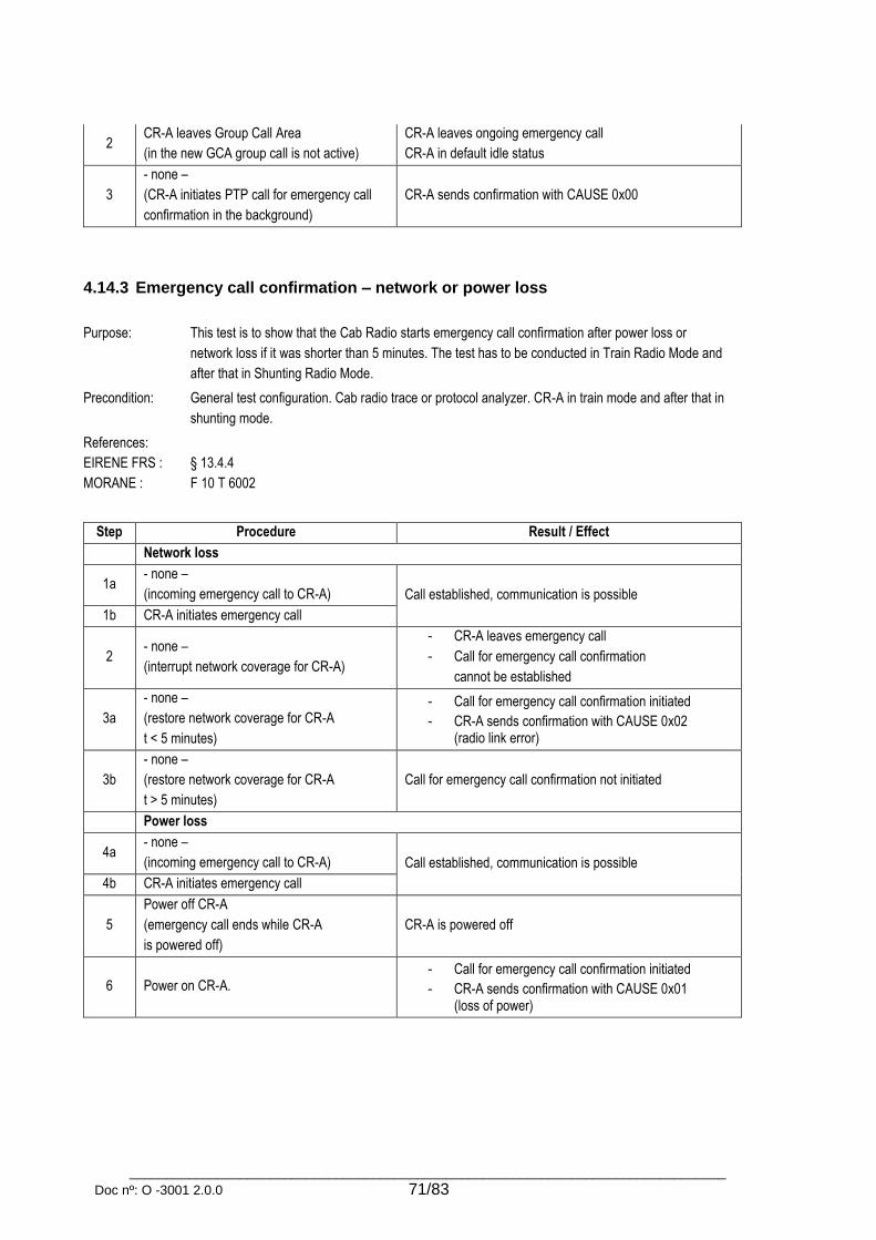
_________________________________________________________________________________
Doc nº: O -3001 2.0.0 71/83
2 CR-A leaves Group Call Area
(in the new GCA group call is not active)
CR-A leaves ongoing emergency call
CR-A in default idle status
3
- none –
(CR-A initiates PTP call for emergency call
confirmation in the background)
CR-A sends confirmation with CAUSE 0x00
4.14.3 Emergency call confirmation – network or power loss
Purpose: This test is to show that the Cab Radio starts emergency call confirmation after power loss or
network loss if it was shorter than 5 minutes. The test has to be conducted in Train Radio Mode and
after that in Shunting Radio Mode.
Precondition: General test configuration. Cab radio trace or protocol analyzer. CR-A in train mode and after that in
shunting mode.
References:
EIRENE FRS :
MORANE :
§ 13.4.4
F 10 T 6002
Step Procedure Result / Effect
Network loss
1a - none –
(incoming emergency call to CR-A) Call established, communication is possible
1b CR-A initiates emergency call
2 - none –
(interrupt network coverage for CR-A)
- CR-A leaves emergency call
- Call for emergency call confirmation
cannot be established
3a
- none –
(restore network coverage for CR-A
t < 5 minutes)
- Call for emergency call confirmation initiated
- CR-A sends confirmation with CAUSE 0x02 (radio link error)
3b
- none –
(restore network coverage for CR-A
t > 5 minutes)
Call for emergency call confirmation not initiated
Power loss
4a - none –
(incoming emergency call to CR-A) Call established, communication is possible
4b CR-A initiates emergency call
5
Power off CR-A
(emergency call ends while CR-A
is powered off)
CR-A is powered off
6 Power on CR-A. - Call for emergency call confirmation initiated
- CR-A sends confirmation with CAUSE 0x01 (loss of power)
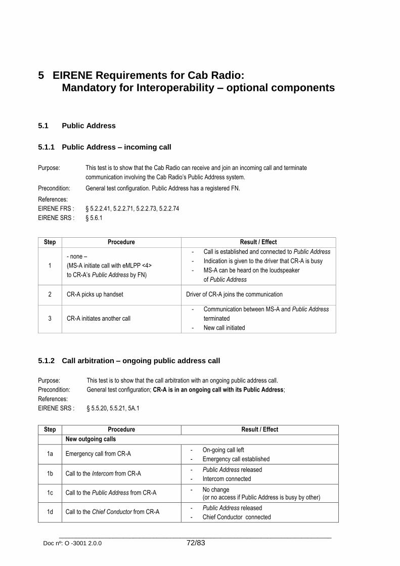
_________________________________________________________________________________
Doc nº: O -3001 2.0.0 72/83
5 EIRENE Requirements for Cab Radio: Mandatory for Interoperability – optional components
5.1 Public Address
5.1.1 Public Address – incoming call
Purpose: This test is to show that the Cab Radio can receive and join an incoming call and terminate
communication involving the Cab Radio’s Public Address system.
Precondition: General test configuration. Public Address has a registered FN.
References:
EIRENE FRS :
EIRENE SRS :
§ 5.2.2.41, 5.2.2.71, 5.2.2.73, 5.2.2.74
§ 5.6.1
Step Procedure Result / Effect
1
- none –
(MS-A initiate call with eMLPP <4>
to CR-A’s Public Address by FN)
- Call is established and connected to Public Address
- Indication is given to the driver that CR-A is busy
- MS-A can be heard on the loudspeaker
of Public Address
2 CR-A picks up handset Driver of CR-A joins the communication
3 CR-A initiates another call
- Communication between MS-A and Public Address
terminated
- New call initiated
5.1.2 Call arbitration – ongoing public address call
Purpose: This test is to show that the call arbitration with an ongoing public address call.
Precondition: General test configuration; CR-A is in an ongoing call with its Public Address;
References:
EIRENE SRS :
§ 5.5.20, 5.5.21, 5A.1
Step Procedure Result / Effect
New outgoing calls
1a Emergency call from CR-A - On-going call left
- Emergency call established
1b Call to the Intercom from CR-A - Public Address released
- Intercom connected
1c Call to the Public Address from CR-A - No change (or no access if Public Address is busy by other)
1d Call to the Chief Conductor from CR-A - Public Address released
- Chief Conductor connected

_________________________________________________________________________________
Doc nº: O -3001 2.0.0 73/83
1e Call to the Controller from CR-A - Public Address released
- Controller connected
New incoming calls
1f Other incoming call - Public Address call is maintained on the handset
- Incoming call connected to the loudspeaker
5.1.3 Call arbitration – ongoing public address call (over radio link)
Purpose: This test is to show that the call arbitration with an ongoing public address call.
Precondition: General test configuration; MS-A is in an ongoing call with CR-A’s Public Address;
References:
EIRENE SRS :
§ 5.5.20, 5.5.21, 5A.1
Step Procedure Result / Effect
New outgoing calls
1a Emergency call from CR-A - On-going call left
- Emergency call established
1b Call to the Intercom from CR-A - Public Address call is maintained
- Intercom connected
1c Call to the Public Address from CR-A - No change (or no access if Public Address is busy by other)
1d Call to the Chief Conductor from CR-A - Call sent (by Public Address)
1e Call to the Controller from CR-A - Public Address released
- Controller connected
New incoming calls
1f Emergency call from controller
- Public Address released
- Incoming call connected
1g “Other drivers in the same area” call
1h Other incoming calls from controller
1i Intercom call from the controller
1j Other incoming call - Public Address call is maintained
- Incoming call is indicated
5.2 Intercom
5.2.1 Intercom system - incoming call
Purpose: This test is to show that the Cab Radio can receive and join an incoming call and terminate
communication involving the Cab Radio’s Intercom system.
Precondition: General test configuration. Intercom has a registered FN
References:
EIRENE FRS :
EIRENE SRS :
§ 5.2.2.41, 5.2.2.71, 5.2.2.73, 5.2.2.74
§ 5.6.1

_________________________________________________________________________________
Doc nº: O -3001 2.0.0 74/83
Step Procedure Result / Effect
1
(MS-A is in an ongoing call with
CR-A’s Intercom)
- none -
- Indication is given to the driver that CR-A is busy
- MS-A can be heard on the Intercom
2 CR-A picks up handset Driver of CR-A joins the communication
3 CR-A initiates another call using MMI menu
- Communication between MS-A and Intercom
terminated
- New call initiated
5.2.2 Call arbitration – ongoing intercom call
Purpose: This test is to show that the call arbitration with an ongoing intercom call.
Precondition: General test configuration; CR-A is in an ongoing call with its Intercom;
References:
EIRENE SRS :
§ 5.5.20, 5.5.21, 5A.1
Step Procedure Result / Effect
New outgoing calls
1a Emergency call from CR-A - On-going call left
- Emergency call established
1b Call to the Intercom from CR-A No change
1c Call to the Public Address from CR-A - On-going call left
- Public Address connected
1d Call to the Chief Conductor from CR-A Call sent (by Public Address or radio)
New incoming calls
1e Other incoming call - Intercom call is maintained on the handset
- Incoming call connected to the loudspeaker
5.2.3 Call arbitration – ongoing intercom call (over radio link)
Purpose: This test is to show that the call arbitration with an ongoing intercom call.
Precondition: General test configuration; MS-A is in an ongoing call with CR-A’s Intercom;
References:
EIRENE SRS :
§ 5.5.20, 5.5.21, 5A.1
Step Procedure Result / Effect
New outgoing calls
1a Emergency call from CR-A - On-going call left
- Emergency call established
1b Call to the Intercom from CR-A No change
1c Call to the Public Address from CR-A - On-going call left
- Public Address connected
1d Call to the Chief Conductor from CR-A Call sent (by Public Address or radio)

_________________________________________________________________________________
Doc nº: O -3001 2.0.0 75/83
1e Call to the Controller from CR-A - On-going call left
- Controller connected
New incoming calls
1f Other incoming call - On-going call left
- Incoming call connected
5.3 Train-borne recorder
Purpose: This test is to show that the Cab Radio records the details of the call confirmation in the train-
borne recorder.
Precondition: General test configuration. CR-A has a train borne recorder connected via Train Interface Unit or
directly by means of a nationally determined interface.
References:
EIRENE FRS :
EIRENE SRS :
MORANE :
§ 5.8.1
§ 5.8.1, 13.5.8
F 10 T 6002, F 12 T 6002
Step Procedure Result / Effect
1 CR-A initiates emergency call Call established, communication possible
2 CR-A terminates emergency call Call terminated
3
- none –
(CR-A starts call confirmation
in the background)
- Call confirmation finished
- Details of the call confirmation stored in the train-
borne recorded:
Entry #1:
- PL_CALL (Priority of confirmed call)
- GC_REF (Group Call Reference)
- FNR (Functional Number)
Entry#2:
- T_DUR (Duration of call)
- CAUSE (Reason for termination)
Entry #3:
- ACK/CAUSE (Value of the final acknowledge)
- N_ACK (Number of retries)

_________________________________________________________________________________
Doc nº: O -3001 2.0.0 76/83
6 EIRENE Requirements for ETCS data only radio: Mandatory for Interoperability
6.1 Dialling calls (ATD)
Purpose: This test is to show that the EDOR can initiate calls with different eMLPP priorities.
Precondition: EDOR test configuration.
References:
EIRENE FRS :
EIRENE SRS :
EURORADIO :
ETSI :
§ 10.2.1, 10.2.2, 16.2.1.3
§ 16.3.2
§ 2.1.1.3, 2.1.2.1, 2.1.2.2, 2.3.1, 4.4.5.2.1, 4.4.5.2.2, 4.4.5.2.3, 4.4.5.3.1, 4.4.5.3.3
EN 122 067, EN 300 904, EN 300 924, EN 300 940, TS 100 549; TS 100 625, TS 100 932,
TS 123 090;TS 124 008
Step Procedure Result / Effect
Description EDOR TE1 EDOR TE1
1 Set automatic call answering to
disable ATS0=0 OK
2 Set the escape sequence to “+++” ATS2=43 OK
3 Select bearer service type AT+CBST=71,0,0 AT+CBST=71,0,0 OK OK
4a Initiate data call to Terminal
equipment with default eMLPP
ATD*75#
<MSISDN> RING
4b Initiate data call to Terminal
equipment with eMLPP <0>
ATD*750#
<MSISDN> RING
4c Initiate data call to Terminal
equipment with eMLPP <1>
ATD*751#
<MSISDN> RING
4d Initiate data call to Terminal
equipment with eMLPP <2>
ATD*752#
<MSISDN> RING
4e Initiate data call to Terminal
equipment with eMLPP <3>
ATD*753#
<MSISDN> RING
4f Initiate data call to Terminal
equipment with eMLPP <4>
ATD*754#
<MSISDN> RING
5 Accept incoming call ATA CONNECT 9600 CONNECT
9600
6 Switch from data to command mode +++ OK
7 Terminate data call ATH OK NO CARRIER

_________________________________________________________________________________
Doc nº: O -3001 2.0.0 77/83
6.2 Terminating calls (ATH)
Purpose: This test is to show that the EDOR can terminate calls.
Precondition: EDOR test configuration.
References:
EIRENE FRS :
EURORADIO :
ETSI :
§ 16.2.1.3
§ 4.4.6.1
TS 124 080
Step Procedure Result / Effect
Description EDOR TE1 EDOR TE1
1 Set automatic call answering to
disable ATS0=0 OK
2 Select bearer service type AT+CBST=71,0,0 AT+CBST=71,0,0 OK OK
3 Initiate data call to Terminal
equipment ATD<MSISDN>
4 Terminate data call ATH OK NO CARRIER
6.3 Connected line identification presentation (+COLP)
Purpose: This test is to show that the EDOR can test, read or set the Connected Line Identification
Presentation.
Precondition: EDOR test configuration.
References:
EIRENE FRS :
EIRENE SRS :
EURORADIO :
ETSI :
§ 4.2.3
§ 4.3.3
§ 2.3.1, 4.4.5.4.1
EN 300 918, TS 100 950, TS 124 080
Step Procedure Result / Effect
Description EDOR TE1 EDOR TE1
1 Test possible values for COLP AT+COLP=? +COLP: (0,1)
OK
2 Set COLP to disable AT+COLP=0 OK
3 Read current value of COLP AT+COLP? +COLP: 0,1
OK*
4 Set COLP to enable AT+COLP=1 OK
5 Read current value of COLP AT+COLP? +COLP: 1,1
OK**
* +COLP: 0,1 if COLP is supported by the network, +COLP: 0,0 if COLP is not supported by the network
** +COLP: 1,1 if COLP is supported by the network, +COLP: 1,0 if COLP is not supported by the network

_________________________________________________________________________________
Doc nº: O -3001 2.0.0 78/83
6.4 Calling line identification presentation (+CLIP)
Purpose: This test is to show that the EDOR can test, read or set the Calling Line Identification
Presentation.
Precondition: EDOR test configuration. CLIP is enabled on the terminal equipment.
References:
EIRENE FRS :
EIRENE SRS :
EURORADIO :
ETSI :
§ 4.2.3
§ 4.3.3
§ 2.3.1, 4.4.6.2.1
EN 300 918, TS 100 950
Step Procedure Result / Effect
Description EDOR TE1 EDOR TE1
1 Test possible values for CLIP AT+CLIP=? +CLIP: (0,1)
OK
2 Set CLIP to disable AT+CLIP=0 OK
3 Read current value of CLIP AT+CLIP? +CLIP: 0,1
OK
4 Set CLIP to enable AT+CLIP=1 OK
5 Read current value of CLIP AT+CLIP? +CLIP: 1,1
OK
6 Set automatic call answering to
disable ATS0=0 OK
7 Set the escape sequence to “+++” ATS2=43 OK
8 Select bearer service type AT+CBST=71,0,0 AT+CBST=71,0,0 OK OK
9 Initiate data call to Terminal
equipment ATD<MSISDN>
RING
+CLIP:
"MSISDN",145
10 Accept incoming call ATA CONNECT 9600 CONNECT
9600
11 Check if data transmission in both directions possible
12 Switch from data to command mode +++ OK
13 Terminate data call ATH OK NO CARRIER
14 Set CLIP to disable AT+CLIP=0 AT+CLIP=0 OK OK
6.5 Incoming call priority presentation (+CRING)
Purpose: This test is to show that the EDOR can show the eMLPP priority of an incoming call.
Precondition: EDOR test configuration.
References:
EIRENE FRS :
EIRENE SRS :
EURORADIO :
§ 10.2.1, 10.2.2
§ 4.3.3
§4.4.6.3.1

_________________________________________________________________________________
Doc nº: O -3001 2.0.0 79/83
Step Procedure Result / Effect
Description EDOR TE1 EDOR TE1
1 Set automatic call answering to
disable ATS0=0 OK
2 Set the escape sequence to “+++” ATS2=43 OK
3 Select bearer service type AT+CBST=71,0,0 AT+CBST=71,0,0 OK OK
4 Set CRC to enable extended format AT+CRC=1 OK
5 Initiate data call to EDOR ATD*751#
<MSISDN>
+CRING:ASYNC
[,<Prio>,
[<subaddr>,
<satype>]]
6 Accept incoming call ATA CONNECT 9600 CONNECT
9600
7 Check if data transmission in both directions possible
8 Switch from data to command mode +++ OK
9 Terminate data call ATH NO CARRIER OK
10 Set CRC to disable extended format AT+CRC=0 OK
6.6 Automatic answering (ATS0)
Purpose: This test is to show that the EDOR can answer incoming calls automatically.
Precondition: EDOR test configuration.
References:
EIRENE FRS :
EURORADIO :
§ 4.2.3
§ 4.4.6.1.1
Step Procedure Result / Effect
Description EDOR TE1 EDOR TE1
1 Set automatic call answering to
enable after 2 rings ATS0=2 OK
2 Set the escape sequence to “+++” ATS2=43 OK
3 Select bearer service type AT+CBST=71,0,0 AT+CBST=71,0,0 OK OK
4 Set the DTE serial link baud rate* AT+IPR=9600 AT+IPR=9600 OK OK
5 Read current used baud rate AT+IPR? AT+IPR? +IPR: 9600
OK
+IPR: 9600
OK
6 Initiate data call to EDOR ATD<MSISDN> RING
RING
7 Accept incoming call automatically CONNECT 9600 CONNECT
9600
8 Check if data transmission in both directions possible
9 Switch from data to command mode +++ OK
10 Terminate data call ATH NO CARRIER OK
* Set the PC com-port to the same baud rate

_________________________________________________________________________________
Doc nº: O -3001 2.0.0 80/83
6.7 Subscriber number (+CNUM)
Purpose: This test is to show that the EDOR can read out the MSISDNs for available services from the SIM
card.
Precondition: EDOR test configuration.
References:
EIRENE SRS :
EURORADIO :
§ 9.7.1, 9.7.4
§ 4.4.10.1.1
Step Procedure Result / Effect
Description EDOR TE1 EDOR TE1
1 Read MSISDN from the SIM card AT+CNUM
+CNUM:
”infotext”,
”MSISDN”
OK
6.8 Network registration (+CREG)
Purpose: This test is to show that the EDOR can show the registration status of the device.
Precondition: EDOR test configuration.
References:
EIRENE FRS :
EURORADIO :
§ 16.2.1.3, 16.2.2.1
§ 4.4.10.2.1, 4.4.10.2.2.3
Step Procedure Result / Effect
Description EDOR TE1 EDOR TE1
1 Enable network registration
unsolicited result code AT+CREG=1 OK
2 Test possible values for
network registration AT+CREG=?
+CREG:
<list of
supported
unsolicited
result codes >
OK
3 Read current value of
network registration AT+CREG?
+CREG: 1,1
OK
4 Interrupt network coverage for EDOR +CREG: 0
5 Restore network coverage for EDOR +CREG: 1
6 Read current value of
network registration AT+CREG?
+CREG: 1,1
OK

_________________________________________________________________________________
Doc nº: O -3001 2.0.0 81/83
6.9 Operator selection (+COPS)
Purpose: This test is to show that the EDOR can register to different GSM network operators.
Precondition: EDOR test configuration.
References:
EIRENE FRS :
EURORADIO :
§ 16.2.1.3, 16.2.2.1
§ 4.4.1, 4.4.10.3.1, 4.4.13.1
Step Procedure Result / Effect
Description EDOR TE1 EDOR T1
1 Set the error result code to
enable and use numeric values AT+CMEE=1 OK
2 Test possible values for
operator selection AT+COPS=?
+COPS:
<list of supported
operators>
OK
3 Set operator selection mode to
automatic AT+COPS=0 OK
4 Read current value of
operator selection AT+COPS?
+COPS:
0,<format>,
<oper>
OK
5 Set invalid value for
operator selection AT+COPS=5
+CME ERROR:
4
6.10 Data call – transparent 4800 bps (V.110)
Purpose: This test is to show that the EDOR can initiate a transparent data call with 4800 bit/s.
Precondition: EDOR test configuration.
References:
EIRENE FRS :
EIRENE SRS :
EURORADIO :
ETSI :
§ 4.2.2
§ 4.1.3.7, 4.3.2
§ 2.1.1.1, 2.1.2.1, 4.4.5.2.3
EN 300 904, EN 300 918
Step Procedure Result / Effect
Description EDOR TE1 EDOR TE1
1 Set automatic call answering to
disable ATS0=0 OK
2 Set the escape sequence to “+++” ATS2=43 OK
3 Select bearer service type AT+CBST=70,0,0 AT+CBST=70,0,0 OK OK
4 Set the DTE serial link baud rate* AT+IPR=4800 AT+IPR=4800 OK OK
5 Read current used baud rate AT+IPR? AT+IPR? +IPR: 4800
OK
+IPR: 4800
OK
6 Initiate data call to Terminal
equipment ATD<MSISDN> RING

_________________________________________________________________________________
Doc nº: O -3001 2.0.0 82/83
7 Accept incoming call ATA CONNECT 4800 CONNECT
4800
8 Check if data transmission in both directions possible
9 Switch from data to command mode +++ OK
10 Terminate data call ATH OK NO CARRIER
* Set the PC com-port to the same baud rate
6.11 Data call – transparent 9600 bps (V.110)
Purpose: This test is to show that the EDOR can initiate a transparent data call with 9600 bit/s.
Precondition: EDOR test configuration.
References:
EIRENE FRS :
EIRENE SRS :
EURORADIO :
ETSI :
§ 4.2.2
§ 4.1.3.7, 4.3.2
§ 2.1.1.1, 2.1.2.1, 4.4.5.2.3
EN 300 904, EN 300 918
Step Procedure Result / Effect
Description EDOR TE1 EDOR TE1
1 Set automatic call answering to
disable ATS0=0 OK
2 Set the escape sequence to “+++” ATS2=43 OK
3 Select bearer service type AT+CBST=71,0,0 AT+CBST=71,0,0 OK OK
4 Set the DTE serial link baud rate* AT+IPR=9600 AT+IPR=9600 OK OK
5 Read current used baud rate AT+IPR? AT+IPR? +IPR: 9600
OK
+IPR: 9600
OK
6 Initiate data call to Terminal
equipment ATD<MSISDN> RING
7 Accept incoming call ATA CONNECT 9600 CONNECT
9600
8 Check if data transmission in both directions possible
9 Switch from data to command mode +++ OK
10 Terminate data call ATH OK NO CARRIER
* Set the PC com-port to the same baud rate
6.12 Call setup with UUS1 (+CUUS1)
Purpose: This test is to show that the EDOR can send UUS1 messages.
Precondition: EDOR test configuration.
References:
EIRENE SRS :
EURORADIO :
ETSI :
§ 4.3.3
§ 2.3.1
EN 301 702, EN 301 710, EN 301 711, TS 122 087

_________________________________________________________________________________
Doc nº: O -3001 2.0.0 83/83
Step Procedure Result / Effect
Description EDOR TE1 EDOR TE1
1
Set UUS1 signalling to send
specified UUIE in ANY message
(e.g. Presentation of Functional
Number)
AT+CUUS1=1,1,0,
"7E000005062143
658709F1"
AT+CUUS1=1,1,0,
"7E000005069078
563402F1"
OK OK
2 Initiate voice call to Terminal
equipment ATD<MSISDN>;
+CUUS1I: 1,
"7E0000050690
78563402F1"
+CRING: …
+CUUS1U: 1,
"7E0000050621
43658709F1"
3 Accept incoming call ATA
+CUUS1I: 3,
"7E0000050690
78563402F1"OK
OK
4 List current calls AT+CLCC AT+CLCC
+CLCC:
1,0,0,0,0,
“MSISDN“, <type>,,4
+CLCC:
1,1,0,0,0,
“MSISDN“,
<type>,,4
5 Terminate voice call ATH OK
+CUUS1U: 2,
"7E0000050621
43658709F1"N
O CARRIER
6 Set UUS1 signalling to send
no UUIE message
AT+CUUS1=0,0,0,
”000500”
AT+CUUS1=0,0,0,
”000500” OK OK