refer to the controlled document located on the …
TRANSCRIPT

FP Manual Rev.6 07/26/2013
Control Copy No: Extranet
TABLE OF CONTENTS PAUL C. RIZZO ASSOCIATES, INC.
FIELD PROCEDURES MANUAL
PROCEDURE REVISION PROCEDURE TITLE DATE
FP-1 2 Packer Testing Procedure 03/02/2013 FP-2 4 Calibration of Pressure Transducers 05/25/2010 FP-3 1 Field Calibration of Flo-Mate Model 2000 04/29/2010
FP-4 4 Field Calibration of YSI 6920 V2-2, Multi-Parameter Water Quality Measurement and Data Collection System
05/24/2011
FP-5 1 Procedure for Monitoring Well Installation 05/25/2011 FP-6 2 Groundwater Monitoring Well Development 05/25/2011
FP-7 0 Procedure for Groundwater Purging, Quality Testing, and Sampling
05/18/2010
FP-8 1 Procedure for Groundwater Level Measurements 05/25/2011
FP-9 0 Procedure for Groundwater Monitoring Well Inspection
04/20/2010
FP-10 0 Cold-Storage Packaging and Transport of Environmental Water and Soil Samples
04/20/2010
FP-11 1 Pumping Test Procedure 05/25/2011 FP-12 1 Slug Test Procedure 05/25/2011
FP-13 0 Quanta G Field Calibration
Procedure is under development and is not included in Rev. 6 of the Field Procedures Manual.
FP-14 1 Field Boring Logs 05/25/2011 FP-15 0 Visual Classification of Rocks 04/06/2010
FP-16 0 Discontinuity Description 04/06/2010
FP-17 0 Calibration of Buckets and Drums 04/29/2010
FP-18 2 Calibration Records 05/25/2011 FP-19 0 Sample Labeling 05/24/2011
FP-20 0 Operation Of The Downhole Camera 09/30/2011
FP-21 0 Soil and Rock Sample Packaging and Transport 03/12/2013
REFER TO THE CONTROLLED DOCUMENT LOCATED ON THE RIZZO EXTRANET FOR THE LATEST VERSION. COPIES PRINTED OR SAVED LOCALLY ARE UNCONTROLLED.

REFER TO THE CONTROLLED DOCUMENT LOCATED ON THE RIZZO EXTRANET FOR THE LATEST VERSION. COPIES PRINTED OR SAVED LOCALLY ARE UNCONTROLLED.

REFER TO THE CONTROLLED DOCUMENT LOCATED ON THE RIZZO EXTRANET FOR THE LATEST VERSION. COPIES PRINTED OR SAVED LOCALLY ARE UNCONTROLLED.

i
TABLE OF CONTENTS
PAGE
1.0 OBJECTIVES AND SCOPE ....................................................................................................... 1
2.0 REFERENCES ......................................................................................................................... 1
3.0 DESCRIPTION OF EQUIPMENT ................................................................................................ 2
3.1 Pneumatic Packer Assembly ............................................................................................ 2
3.1.1 Single-Packer Arrangement ...................................................................................... 2
3.1.2 Double-Packer Arrangement .................................................................................... 2
3.2 Pipe String ........................................................................................................................ 3
3.3 Pump and Instrument String ............................................................................................. 3
3.4 Compressed Gas System .................................................................................................. 5
3.5 Tools and Miscellaneous Equipment ............................................................................... 6
4.0 CALIBRATION REQUIREMENTS .............................................................................................. 7
5.0 PROCEDURES ........................................................................................................................ 7
5.1 Equipment Setup (Driller) ................................................................................................ 7
5.1.1 Assembling the Packer .............................................................................................. 7
5.1.2 Packer Measurements ............................................................................................... 8
5.1.3 Gas Leak Test ........................................................................................................... 9
5.1.4 Arrangement of Instrument String .......................................................................... 11
5.2 Testing Procedure ........................................................................................................... 11
5.2.1 Test Preliminaries ................................................................................................... 11
5.2.2 Test Setup................................................................................................................ 12
5.2.3 Test Initiation .......................................................................................................... 19
5.2.4 Data Collection ....................................................................................................... 20
5.3 Test Termination ............................................................................................................ 21
REFER TO THE CONTROLLED DOCUMENT LOCATED ON THE RIZZO EXTRANET FOR THE LATEST VERSION. COPIES PRINTED OR SAVED LOCALLY ARE UNCONTROLLED.

TABLE OF CONTENTS (CONTINUED)
ii
6.0 SUITABLE ENVIRONMENTAL CONDITIONS .......................................................................... 21
7.0 PERSONNEL QUALIFICATIONS AND TRAINING RECORDS ..................................................... 21
8.0 RECORD KEEPING ............................................................................................................... 22
FIGURES
FORMS
APPENDIX A – TROUBLESHOOTING PROCEDURES
APPENDIX B - DATA REDUCTION
REFER TO THE CONTROLLED DOCUMENT LOCATED ON THE RIZZO EXTRANET FOR THE LATEST VERSION. COPIES PRINTED OR SAVED LOCALLY ARE UNCONTROLLED.

iii
LIST OF TABLES
TABLE NO. TITLE
B-1 PACKER TEST DATA REDUCTION SHEET
B-2 EXAMPLE PACKER TESTING FIELD DATA FORM AND CORRESPONDING DATA REDUCTION
B-3 FRICTION LOSS IN A SCHEDULE 40 STEEL PIPE
B-4 HAZEN-WILLIAMS ROUGHNESS COEFFICIENT = 100
B-5 COMMON MATERIALS AND ASSOCIATED HAZEN-WILLIAMS ROUGHNESS COEFFICIENT (C) VALUES
REFER TO THE CONTROLLED DOCUMENT LOCATED ON THE RIZZO EXTRANET FOR THE LATEST VERSION. COPIES PRINTED OR SAVED LOCALLY ARE UNCONTROLLED.

iv
LIST OF FIGURES
FIGURE NO. TITLE
1 PACKER ASSEMBLY
2 PACKER TESTING SETUP
3 INSTRUMENT STRING
B-1 HEAD LOSS – 3/4” ID SCHEDULE 40 STEEL PIPE
B-2 HEAD LOSS – 1 1/4” ID SCHEDULE 40 STEEL PIPE
B-3 HEAD LOSS – 2” ID RUBBER HOSE
REFER TO THE CONTROLLED DOCUMENT LOCATED ON THE RIZZO EXTRANET FOR THE LATEST VERSION. COPIES PRINTED OR SAVED LOCALLY ARE UNCONTROLLED.

Page 1 of 22 FP-1, Rev. 2
March 1, 2013
PACKER TESTING PROCEDURE
FP-1, REVISION 2 MARCH 1, 2013
1.0 OBJECTIVES AND SCOPE
This procedure describes the process for conducting borehole packer testing in saturated bedrock strata. Data obtained from the packer testing procedure are used to evaluate the hydraulic conductivity of a specific test interval. This procedure is meant to provide a general framework for the packer testing process; however, site-specific conditions may result in slight modifications to the methodology. Troubleshooting procedures and data reduction are also discussed in Appendices A and B, respectively.
2.0 REFERENCES
2.1 BUREC, 1995, “Ground Water Manual,” United States Department of the Interior, Bureau of Reclamation, Second Edition, 1995. 2.2 Driscoll, F.G., 1986, “Groundwater and Wells (Second Edition),” Johnson Division, St. Paul, Minnesota, 1986.
2.3 Hauser, B., 2000 “Chapter 91 – Hydraulics” in Dorf, R.C., “The Engineering Handbook,” CRC Press LLC, Boca Raton, Florida, 2000. 2.4 Paul C. Rizzo Associates, Inc. (RIZZO), Packer Testing Field Data Form. 2.5 PCR Holdings, Inc., Health and Safety Manual 2.6 RIZZO QP-3, Personnel Qualifications 2.7 RIZZO QP-25, Records Control. 2.8 RIZZO QP-27, Field Activity Daily Logs 2.9 Zeigler, T.W., 1976, “Determination of Rock Mass Permeability,” U.S. Army Engineer Waterways Experiment Station, Soils and Pavements Laboratory, Technical Report S-76-2, January 1976.
REFER TO THE CONTROLLED DOCUMENT LOCATED ON THE RIZZO EXTRANET FOR THE LATEST VERSION. COPIES PRINTED OR SAVED LOCALLY ARE UNCONTROLLED.

Page 2 of 22 FP-1, Rev. 2
March 1, 2013
3.0 DESCRIPTION OF EQUIPMENT 3.1 Pneumatic Packer Assembly
There are several types of packers; however, only the gas-inflated pneumatic packer will be considered in this procedure. The pneumatic packer consists of an expandable rubber gland that is secured at each end to a machined aluminum or steel head. The two most commonly used types of pneumatic packers involve either the rubber gland being banded onto the head or the rubber gland being screwed into the head. In both setups, a conductor pipe passes through each head and inside the gland, allowing water to be pumped through the assembly while maintaining an airtight system. Compression fittings in the heads allow for the attachment of a gas line, which inflates the packer.
3.1.1 Single-Packer Arrangement
A single-packer test utilizes one packer to seal off the portion of a borehole that lies below the packer (Figure 1). The compression fitting in the bottom head is replaced with a plug, and the conductor pipe discharges water through its unplugged end below the packer. The gas line is attached to the compression fitting on the top head, and the conductor pipe is connected to the pipe string. Single-packer tests are typically conducted as a borehole is being advanced (i.e., the drill crew alternates between drilling and testing in the borehole).
3.1.2 Double-Packer Arrangement
A double-packer test utilizes two packers to isolate a specific test zone. The two packers are separated by a perforated conductor pipe, which is plugged at the bottom of the packer assembly (Figures 1 and 2). Water is discharged through the perforated portion of the conductor pipe into the zone between the two packers. The length of the perforated conductor pipe determines the length of the test interval (generally 10 feet (ft)). The total length of the test zone should include an allowance for the heads and other fittings to the conductor, as defined in Section 5.1.2. All joints must be watertight. The bottom-most compression fitting is replaced with a plug, and a gas line is attached between the two packers. This line should be taped or attached securely to the perforated conductor. On packers where the rubber gland is screwed onto the head (e.g., DAMCO and Tigre Tierra models), one of the two heads slides along the conductor pipe when the gland is inflated. A sufficient amount of slack must be left in the gas line
REFER TO THE CONTROLLED DOCUMENT LOCATED ON THE RIZZO EXTRANET FOR THE LATEST VERSION. COPIES PRINTED OR SAVED LOCALLY ARE UNCONTROLLED.

Page 3 of 22 FP-1, Rev. 2
March 1, 2013
between the packers to allow this movement. The topmost compression fitting is attached to a gas line leading to a compressed gas tank located at the ground surface. The top of the conductor pipe is attached to the pipe string by means of a threaded fitting. Note: Although the glands are attached differently in each method, there is no difference in the data obtained from the banded type packers and the screw-on type packers (i.e., there is no particular situation where one type of packer should be used instead of the other).
3.2 Pipe String
The pipe string is used to lower the packer assembly to the test zone, as well as conveying water to the test zone. The pipe should be of sufficient tensile strength to support the weight of the string and withstand the pressures generated during the test; ¾ or 1 ¼-inch (in.)-diameter galvanized or black steel water pipe is commonly used. The effects of the friction head become more significant with a smaller pipe size. Measurements of the length and internal diameter of the pipe string are required to estimate the head loss due to friction within the pipe. The length of pipe string should be measured (calculated) for each test interval separately. The pipes should all be of uniform length. If this is not possible, each pipe should be measured individually. One odd-length pipe may be used at the top of the string. The pipe and threads should be in good condition and all joints should be wrench-tight to prevent leaks.
3.3 Pump and Instrument String
The aboveground test equipment consists of a pump, a water reservoir, a surge tank (optional, used if the pump does not pump at a steady rate), bypass and line valves, a water meter, an optional sight flow indicator, a water pressure gage, hoses, and an elbow or swivel, which attaches to the pipe string (Figure 3). The pump should be capable of delivering water at a greater rate than the rate at which the test zone will accept the water at the desired test pressure. For low to medium permeability rocks, the pump mounted on the drill rig is usually sufficient. For high permeability rocks, a larger pump may be necessary. The pump should deliver a constant discharge at a constant pressure, without fluctuations or surges. A reservoir of test water is required and is typically provided by a water tank or a water truck. The test water must be clean with minimal turbidity, as suspended solids may plug the voids in the formation and invalidate the test. It is generally preferable that the test water be slightly warmer than the natural groundwater in
REFER TO THE CONTROLLED DOCUMENT LOCATED ON THE RIZZO EXTRANET FOR THE LATEST VERSION. COPIES PRINTED OR SAVED LOCALLY ARE UNCONTROLLED.

Page 4 of 22 FP-1, Rev. 2
March 1, 2013
the formation. The warm temperature will prevent gas from coming out of the solution from the test water, which could potentially affect the test results. The pump discharge outlet is attached by means of a flexible hose to the rest of the system. The portion of the system from the pump discharge hose through the flow meter and pressure gage is assembled using galvanized or black steel water pipe. The discharge downstream of the gage is attached to an elbow (or swivel) with a second hose. The diameter of the pipe should be equal to or larger than the inlet/outlet diameters of the water meter. Hose diameters should be of the same size or larger than the pipe diameter. A simple surge line can be made by placing a tee in the line between the pump and valve arrangement and adding a 3-ft length of pipe to the tee. The pipe should be oriented vertically and the top end capped. This will dampen pressure surges in the system and steady the water pressure gage. With a good pump, this may not be necessary. With a worn pump, several may be required, one after the other. The performance of the pressure gage is the indicator as to whether or not a surge line or surge tank is required. The valve arrangement is designed to both regulate the water pressure and protect the water meter and the pressure gage. A tee is placed in the line downstream of the surge tank. The tee acts as a bypass and returns water to the reservoir. A globe valve is placed in the bypass line and is used to regulate the pressure in the system. This should not be a gate valve. The line valve is located downstream of the tee. This valve is always either full open or full closed and may be a gate valve. The water meter may be any commercially available device for measuring the volume of flow. It is recommended that the meter reads in gallons rather than cubic ft, and that the smallest division is 0.1 gallon. The meter should be placed a minimum of 10 inlet diameters below the line valve (e.g., a piece of straight pipe at least 10 in. long should be placed between the line valve and a water meter with a 1-in.- diameter inlet). The meter will operate in any orientation and may be turned on its side, if convenient. The use of unions to attach the meter onto the pipe string may be desirable, as this facilitates viewing of the meter. As an option, a sight flow indicator may be installed downstream of the meter. This is a device which contains a rotor or propeller that is visible through a window and rotates when water flows through the system. It is useful for verifying that the meter is not stuck when testing a no-take zone. Most meters now include a sight flow indicator, making a separate sight flow indicator unnecessary. The water pressure gage is placed a minimum of 10 pipe diameters downstream of the flow meter (or sight flow indicator, if used). The gage is attached to a tee,
REFER TO THE CONTROLLED DOCUMENT LOCATED ON THE RIZZO EXTRANET FOR THE LATEST VERSION. COPIES PRINTED OR SAVED LOCALLY ARE UNCONTROLLED.

Page 5 of 22 FP-1, Rev. 2
March 1, 2013
which is reduced with a series of bushings to the size of the gage nipple. Because of the appearance of the reducing bushings, this assembly is often called the Christmas Tree. The pressure gage should be marked in 2 pounds per square inch (psi) increments and have a capacity in the range of 200 to 250 psi. The components of the instrument string should be arranged so that the bypass valve can be operated while easily observing the pressure gage. The instrument string is attached to a swivel or elbow by means of a hose. The hose should be of the same inside diameter as the pipe of the instrument string. The elbow is attached to the pipe string. Because of the friction losses in the hose and elbow, the ideal location for the water pressure gage is between the elbow and the pipe string. In this case, the pressure gage should be attached a minimum of 10 pipe diameters below the elbow. It is not always practical to use this setup, so it should be considered as optional. However, when the pressure gage is mounted upstream of the elbow, the friction loss through the hose and elbow should be included in the calculations; therefore, measurements of the diameter and length of hose used will need to be recorded.
3.4 Compressed Gas System
An inert compressed gas (such as nitrogen) or compressed air is used to inflate the packers. Oxygen or other flammable gases are not to be used to inflate the packers. Gas tanks are to be transported in an upright position and secured with a chain or cable. Whenever a tank is moved, the protective cap must be securely screwed on. Bottles should never be moved while the regulator is attached. When in use, gas bottles are to be in an upright position and securely chained to a stationary object or support. The delivery pressure is controlled by a regulator. The regulator is attached to the tank with a threaded brass connection, which differs for various gases. The regulator connection and gas tank should be checked for compatibility before leaving the lab or supplier. The regulator must also be capable of delivering the working pressure required to seat the packers (Section 5.2.1.4 and Section 5.2.2.3). The maximum delivery pressure varies with the regulator model but is generally about half the full range of the pressure gage. The regulator is connected to the packer(s) with a gas line. The line is typically ¼-in. polyethylene or nylon tubing, which is connected to the regulator and packer with special brass compression fittings. Breaks in the line can be repaired with a union. Extra compression nuts and plastic ferrules should be kept in the field during testing in order to perform any necessary repairs.
REFER TO THE CONTROLLED DOCUMENT LOCATED ON THE RIZZO EXTRANET FOR THE LATEST VERSION. COPIES PRINTED OR SAVED LOCALLY ARE UNCONTROLLED.

Page 6 of 22 FP-1, Rev. 2
March 1, 2013
It is convenient to place a valve in the line at the regulator to release the pressure in the packer(s) at the completion of each test. This makes it unnecessary to detach the gas line at the regulator to release the packers, which may damage the ferrule and cause a leak.
3.5 Tools and Miscellaneous Equipment
A basic tool kit used by the driller for assembling and repairing the equipment should include the following:
2 x ⅜-in. open end wrenches
2 x 71⁄16-in. open end wrenches
2 x ½-in. open end wrenches
2 x 18-in. (or larger) pipe wrenches
Adjustable wrench
Banding tool
Spare bands
Spare compression nuts and ferrules
Spare gas line unions
Teflon tape
The open end wrenches are used to assemble/disassemble the gas line fittings and to attach gages. The adjustable wrench is used to tighten/loosen the regulator connection. The pipe wrenches are used to assemble the pipe and instrument strings. Some packers disassemble with pipe wrenches for replacing the gland. On others, the gland is banded onto the steel head of the packer. Spare parts should be kept available on-site, especially glands. Other spare parts kept on site should include gas line fittings, pipe fittings, and adapters. Although not always feasible, it is recommended to have spare gages and a spare water flow meter on site. Additional equipment that RIZZO field personnel should have on site includes the following:
Calculator
Field forms
Timepiece (e.g., a stopwatch)
Clipboard
REFER TO THE CONTROLLED DOCUMENT LOCATED ON THE RIZZO EXTRANET FOR THE LATEST VERSION. COPIES PRINTED OR SAVED LOCALLY ARE UNCONTROLLED.

Page 7 of 22 FP-1, Rev. 2
March 1, 2013
Writing implements
Electric water level indicator
Tape measure or folding rule
4.0 CALIBRATION REQUIREMENTS The following equipment is required to be calibrated per the requirements of the RIZZO QA Program and documented before the commencement of packer testing: Water flow meter
Water pressure gage
If the equipment belongs to the contractor, field personnel should confirm that the serial number listed on the calibration documentation matches the serial number of the equipment used for testing. A copy of the calibration documentation should be made and kept on file with the corresponding Packer Testing Field Data Forms.
5.0 PROCEDURES
Prior to the commencement of field work, all on-site personnel should review the site-specific Work Plan and/or Health And Safety Plan (if applicable) to determine if any relevant site-specific health and safety concerns exist or procedures are to be followed. If no site-specific work plan and/or health and safety plan is in effect, work should be performed in accordance with the PCR Holdings, Inc. Health and Safety Manual.
5.1 Equipment Setup (Driller)
5.1.1 Assembling the Packer
5.1.1.1 For a single-packer arrangement, follow these steps:
Replace the gas line fitting at the bottom of the packer with a plug. Use teflon tape to ensure an airtight seal.
Check that the bottom of the conductor pipe is unplugged.
Attach the top of the conductor pipe to the pipe string. This may require a reducing bell or bushing.
REFER TO THE CONTROLLED DOCUMENT LOCATED ON THE RIZZO EXTRANET FOR THE LATEST VERSION. COPIES PRINTED OR SAVED LOCALLY ARE UNCONTROLLED.

Page 8 of 22 FP-1, Rev. 2
March 1, 2013
Secure the gas line to the compression fitting at the top of the packer. Tape the gas line securely to the conductor pipe and pipe string. For packers on which the connectors slide along the conductor pipe, allow enough slack in the gas line to accommodate the movement.
5.1.1.2 For a double-packer arrangement:
Check that the bottom gas line fitting of the lower
packer has been replaced with a plug.
Attach the upper and lower packers to the perforated conductor pipe.
Plug the bottom end of the conductor pipe below the lower packer.
Attach the gas line between the two packers. Secure the line to the conductor pipe. For packers on which the connectors slide on the conductor pipe, allow enough slack to accommodate the movement.
Attach the top part of the conductor pipe to the pipe string.
Attach the gas line to the compression fitting at the top of the upper packer. Attach the line securely to the conductor and pipe string. For packers on which the connectors slide on the conductor pipe, allow enough slack to accommodate the movement.
Note that all pipe joints are to be wrench-tight to ensure a watertight system. In the gas line, all connections involving pipe threads are to use teflon tape to ensure air-tightness. Compression nuts and the regulator connection (to the gas tank) do not require teflon tape.
5.1.2 Packer Measurements
After the packer has been assembled, record the following measurements on the Packer Testing Field Data Form:
5.1.2.1 For a single-packer arrangement:
Measure the total length from the top of the
coupling at the upper end of the conductor pipe to
REFER TO THE CONTROLLED DOCUMENT LOCATED ON THE RIZZO EXTRANET FOR THE LATEST VERSION. COPIES PRINTED OR SAVED LOCALLY ARE UNCONTROLLED.

Page 9 of 22 FP-1, Rev. 2
March 1, 2013
the open lower end of the conductor pipe (Distance A, Figure 1).
Measure the distance from the top of the coupling at the upper end of the conductor pipe to the edge of the exposed rubber at the bottom end of the packer. If the gland is banded to the connectors, measure from the coupling to the top band at the bottom of the packer (Distance C, Figure 1).
5.1.2.2 For a double-packer arrangement:
Measure the total length from the top of the
coupling at the upper end of the conductor pipe to the plug at the lower end of the conductor pipe (Distance A, Figure 1).
Measure the length of the test zone between the two packers. For packers that have banded glands, this is the distance between the bottommost band at the top end of the lower packer and the topmost band at the bottom end of the upper packer (Distance B, Figure 1). Note that this is the distance between the portions of the packers that make contact with the boring wall. Other types of packers, such as the DAMCO type packer, have one head which slides on the conductor pipe and one non-sliding head. The packer assembly should be set up so that both non-sliding heads face the test zone, allowing for an accurate measurement of the test zone interval. The heads are smaller in diameter than the borehole, therefore, the expanded glands of the packer act as the limits of the test zone (Distance B, Figure 1). This results in both the DAMCO and banded type packers having an equivalent test zone length.
Measure the distance from the top of the coupling at the upper end of the conductor pipe to the topmost band at the bottom of the upper packer (or to the end of the exposed gland at the bottom of the upper packer). This is Distance C, on Figure 1.
5.1.3 Gas Leak Test
Check for leaks in the compressed gas system by following these steps:
REFER TO THE CONTROLLED DOCUMENT LOCATED ON THE RIZZO EXTRANET FOR THE LATEST VERSION. COPIES PRINTED OR SAVED LOCALLY ARE UNCONTROLLED.

Page 10 of 22 FP-1, Rev. 2
March 1, 2013
5.1.3.1 Lower the packer(s) into the borehole. Accurately measure each length of pipe as it goes into the borehole. Make sure all couplings are wrench-tight before performing the measurements.
5.1.3.2 If there is a sufficient length of casing in the boring to contain
the entire length of the packer assembly, set the assembly within the casing. If there is not sufficient casing, lower the assembly to competent rock.
5.1.3.3 Inflate the packers:
Back off the regulator.
Open the gas tank valve.
Slowly increase the delivery pressure to 100 psi.
Wait several minutes for pressures in the system to equalize.
Close the gas tank valve.
5.1.3.4 Observe the delivery pressure gage on the regulator. If it remains steady at one pressure, the system does not leak. If the gage continues to fall, deflate the packers as explained below, withdraw the tools from the hole, and check for leaks as explained in Appendix A, Troubleshooting Procedures.
5.1.3.5 Deflate the packers by opening the valve in the gas line or, if
there is no valve, removing the gas line at the compression fitting to the regulator.
5.1.3.6 Back off the regulator. 5.1.3.7 By placing a finger over the discharge from the gas line or
valve, check that the pressure has been completely let off of the packers. (This can take several minutes.) When there is no gas pressure on the packers, they may be withdrawn for leak inspection or moved to the next test zone.
5.1.3.8 RIZZO field personnel will record the results of the gas leak
test on the Field Activity Daily Log (FADL) per RIZZO QP-27.
REFER TO THE CONTROLLED DOCUMENT LOCATED ON THE RIZZO EXTRANET FOR THE LATEST VERSION. COPIES PRINTED OR SAVED LOCALLY ARE UNCONTROLLED.

Page 11 of 22 FP-1, Rev. 2
March 1, 2013
5.1.4 Arrangement of Instrument String
Equipment within the instrument string (above-ground) should be arranged as shown on Figure 3. All connections should be kept as short and straight as possible, with a minimum number of changes in the diameter of hoses and pipes. All connections between the water flow meter and the test section should be wrench-tightened to ensure that no loss of water occurs. Note the location of the pressure gage (upstream or downstream of the elbow) in the Remarks section of the Packer Testing Field Data Form.
5.2 Testing Procedure
5.2.1 Test Preliminaries
5.2.1.1 Determination of Zones to be Tested
Packer tests can either be performed in several continuous intervals across the entire length of the borehole, or at intervals in pre-selected locations within the borehole. Packer testing is often used to assist in the placement of monitoring wells in zones which are highly permeable. In order to determine zones that are likely to be permeable, it is necessary for the field personnel to have access to all available information relevant to the borehole being tested (e.g., the rock core, boring logs, and information obtained during drilling). In addition to determining highly permeable zones, packer testing may be used to confirm zones that are suspected to have a low permeability (e.g., aquitards or aquicludes).
5.2.1.2 Cleaning Test Sections
Prior to the initiation of testing, the test interval should be thoroughly flushed and surged to remove cuttings trapped in fractures and pores. Cuttings can plug pores and fractures, reducing the amount of water pumped during the test and in turn yielding an erroneously low permeability estimate. If a single-packer arrangement is used, the interval should be cleaned prior to each test. In the case that a completed borehole is tested using a double-packer arrangement, the entire hole can be cleaned in one operation.
REFER TO THE CONTROLLED DOCUMENT LOCATED ON THE RIZZO EXTRANET FOR THE LATEST VERSION. COPIES PRINTED OR SAVED LOCALLY ARE UNCONTROLLED.

Page 12 of 22 FP-1, Rev. 2
March 1, 2013
5.2.1.3 Determining Length of Tested Sections
The optimal length of a tested section is typically around 10 ft (approximately 3 meters (m)), although the length can be adjusted to account for properties of the rock being tested. If the test section takes more water than the pump can deliver (i.e., no back pressure can be developed in the test section), the test length should be shortened. Test sections should be at least five times greater than the borehole diameter, with the exception of a situation where a single discrete fracture or thin water-bearing zone is to be isolated and tested.
5.2.1.4 Determining Packer Expansion Pressure
The expansion pressure of the packer(s), which is the pressure needed to overcome the elasticity of the packer(s), may already be known from the manufacturers’ specifications. If this is not the case, follow this procedure to obtain the expansion pressure: Lower the packer assembly into the boring that is to be tested. Slowly inflate the packer(s) while simultaneously moving the packer assembly upward and downward within the borehole. When the packer(s) will no longer move within the borehole, note the delivery pressure (i.e., expansion pressure) on the Packer Testing Field Data Form.
5.2.1.5 Determine Initial Depth to Groundwater
Determine the initial depth to groundwater within the borehole to be tested. This measurement should be made from the ground surface with an electric water level indicator. Place the resultant value on the Packer Testing Field Data Form.
5.2.2 Test Setup
Once all necessary instrument string equipment has been set up and all the preliminary steps have been performed, begin the test setup procedures as follows:
5.2.2.1 Lower the packer(s) to the test zone, accurately measuring the
length of the pipe string from the top of the conductor pipe (coupling) to the ground surface (signified by L on the Packer Testing Field Data Form). In the case of a double packer setup, the tests generally begin at the deepest test zone and work upward so that loose material, which may be dislodged by the packers and obstruct the boring, will fall clear of the zones yet
REFER TO THE CONTROLLED DOCUMENT LOCATED ON THE RIZZO EXTRANET FOR THE LATEST VERSION. COPIES PRINTED OR SAVED LOCALLY ARE UNCONTROLLED.

Page 13 of 22 FP-1, Rev. 2
March 1, 2013
to be tested. Also note that the bottom of the tool should typically never be lowered further than to a point of about 10 to 20 ft (3 to 6 m) above the bottom of the boring. This keeps the tool out of cuttings and debris, which may collect at the bottom of the hole and which may damage or jam the packers. If the depth to the bottom of the boring is known, it may be acceptable to decrease the distance between the bottom of the lowest test interval and the bottom of the boring.
Note that by measuring the length of the pipe string from the
top of the conductor coupling to ground surface:
The depth to the top of the test zone can be determined by adding the Distance C (Figure 2) to the pipe string length (L). This value should be placed on the Packer Testing Field Data Form under the column labeled Top of Test Zone, L2. The value of L2 is interval dependent.
The depth to the bottom of the test zone (for the double-packer arrangement) can be determined by adding the test zone length (Distance B, Figure 1) to the depth to the top of the test zone (L2). This value should be placed on the Packer Testing Field Data Form under the column labeled Bottom of Test Zone, L1. When using the single-packer arrangement, the bottom of the test zone (L1) is equivalent to the depth to the bottom of the borehole. Appropriate equipment (e.g., a weighted measuring tape) should be used to determine L1 with this arrangement. The value of L1 is interval dependent for both the single and double-packer setup.
The total length of tools in the hole can be determined by adding the total length of the packer assembly (Distance A, Figure 1) to the length of the pipe string (L). This value is interval dependent.
5.2.2.2 Lock the pipe string at the proper depth with a pipe clamp or pipe vise.
5.2.2.3 Determine the pressure needed to inflate the pneumatic
packer(s). To properly inflate the packer(s), several variables must be considered, including:
REFER TO THE CONTROLLED DOCUMENT LOCATED ON THE RIZZO EXTRANET FOR THE LATEST VERSION. COPIES PRINTED OR SAVED LOCALLY ARE UNCONTROLLED.

Page 14 of 22 FP-1, Rev. 2
March 1, 2013
Expansion pressure
Pressure head at the test interval
The pressure the pump will place on the system
The expansion pressure of the packer(s) has already been determined (Section 5.2.1.4) and noted on the Packer Testing Field Data Form. To obtain the pressure head at the test interval, it is necessary to know the height of the water column above the centerpoint of the interval to be tested. The centerpoint of the interval can be calculated by using the values determined in Section 5.2.2.1 and the following relation:
Midpoint of Interval =
Where, L1 = Depth (bgs) to the bottom of the tested interval
L2 = Depth (bgs) to the top of the tested interval
When using the double-packer arrangement, an interval specific groundwater level cannot yet be collected, therefore, the initial depth to groundwater measurement (Section 5.2.1.5) should be used. The initial depth to groundwater measurement represents the interval with the highest groundwater head within the borehole (due to artesian pressure). Using this value to obtain pressure head at the test interval results in a conservative value, which should allow for adequate inflation to prevent packer leakage, while still preventing over-inflation and bursting of the packers. When using a single-packer arrangement, the initial depth to water measurement will provide a representative estimate of the head of the interval to be tested. The initial pressure head at the test interval can be estimated for either setup using the following relation:
Water Column Height (ft) = Centerpoint of Interval (ft) – Initial depth to Groundwater (ft)
The pressure head at the test interval can be further converted into an equivalent water pressure by the relation:
Column water pressure (psi) = Water Column Height (ft) x 0.433 (psi/ft)
REFER TO THE CONTROLLED DOCUMENT LOCATED ON THE RIZZO EXTRANET FOR THE LATEST VERSION. COPIES PRINTED OR SAVED LOCALLY ARE UNCONTROLLED.

Page 15 of 22 FP-1, Rev. 2
March 1, 2013
If measurements are made in metric units (kilopascals, kPa), use the following relation to convert into an equivalent water pressure : Column water pressure (kPa) = Water Column Height (m) x 9.795 (kPa/m) This is the pressure that the packer(s) will need to overcome due to the hydraulic head within the tested interval.
To determine the packer inflation pressure, sum the expansion pressure (Section 5.2.1.4), the pressure head at the test interval, the pressure that the pump will place on the system (as measured at the water pressure gage), and an additional 50 psi to allow for approximations and pressure surges. The gage pressure should generally not exceed the sum of 25 psi and the pressure head at the test interval (already accounted for in determination of packer inflation pressure), therefore, when determining packer inflation pressure, 25 psi is to be used as the pressure the pump will place on the system. The desired packer inflation pressure can be obtained by the following relation: Inflation Pressure = Expansion Pressure + Column Pressure + 75 psi
Note: The column pressure is interval dependent (i.e., the centerpoint of each test interval will vary), therefore, the packer inflation pressure should be recalculated for each interval tested within the borehole. When using a single-packer arrangement, the depth to groundwater will also vary for each interval tested. The depth to groundwater determined for the preceding interval, as explained in Section 5.2.2.5, should be used to determine the water column pressure. Additionally, if metric is used, note that 1 psi is equivalent to 6.895 kPa.
5.2.2.4 Inflate the packers using the procedure outlined above (Section 5.2.2.3). Note the pressure (which can be found on the delivery pressure gage of the regulator) to 1 psi accuracy on the Packer Testing Field Data Form under the column titled Packer Inflation Pressure. Assuming that packer leakage is not occurring, the inflation pressure should remain constant throughout a specific test interval. If packer leakage is suspected (i.e., water flowing from the conductor pipe is
REFER TO THE CONTROLLED DOCUMENT LOCATED ON THE RIZZO EXTRANET FOR THE LATEST VERSION. COPIES PRINTED OR SAVED LOCALLY ARE UNCONTROLLED.

Page 16 of 22 FP-1, Rev. 2
March 1, 2013
escaping the tested section due to a poorly seated packer), increase the packer inflation pressure (making sure not to exceed the manufacturer’s recommended maximum differential pressure). If the problem persists, see Appendix A, Troubleshooting Procedures.
5.2.2.5 Allow the groundwater within the pipe string to equilibrate to the hydraulic head within the tested interval. To determine when the groundwater within the pipe string has equilibrated to the head of the test zone, perform groundwater measurements at a regular interval (e.g., one to two minutes) using an electric water level indicator. Continue measurements until successive readings yield the same depth to groundwater measurement. This may take several minutes, depending upon the hydraulic properties of the interval being testing. When the water level has equilibrated within the pipe string, record the value on the Packer Testing Field Data Form under the column headed Depth to Groundwater, Hw. Measurements should be recorded as a depth to water below ground surface (i.e., the height of the pipe string above ground surface from where the measurement is taken should be accounted for).
In the case of a flowing artesian test zone, follow these instructions to obtain an HW value: Attach the elbow to the pipe string and connect the
hose (if applicable).
Close the valve upstream of the water pressure gage.
Obtain a reading (psi or kPa) from the water pressure gage. This is the total hydraulic head of the test zone interval.
Convert the pressure (psi or kPa) to an appropriate measurement of length (ft or meters) of water by the following relations:
. / = Water Column Height (ft)
Or
. / = Water Column Height (m)
REFER TO THE CONTROLLED DOCUMENT LOCATED ON THE RIZZO EXTRANET FOR THE LATEST VERSION. COPIES PRINTED OR SAVED LOCALLY ARE UNCONTROLLED.

Page 17 of 22 FP-1, Rev. 2
March 1, 2013
Determine the height of the water column above ground surface by the following relation:
Water Column Height -
= Height of Water Column
Above Ground Surface Where, L1 = Depth (bgs) to the bottom of the tested interval
L2 = Depth (bgs) to the top of the tested interval
Note the height of the water column above ground
surface on the Packer Testing Field Data Form as a negative value. Place a note in the remarks section stating that the interval was flowing artesian.
If the test interval is above the water level in the boring, enter the depth to the center of the test zone on the Packer Testing Field Data Form under the HW column. Note: The depth to groundwater is interval specific and will need to be determined for each interval separately.
5.2.2.6 Determining Proper Testing Pressure
In order to obtain reasonable hydraulic conductivity estimates for each test interval, flow within the tested section must be laminar. To maintain laminar flow, the water gage pressure should be kept within interval specific limits during the test. The calculated limits should be placed on the Packer Testing Field Data Form under the column titled Water Gage Pressure Limits. For a test conducted within the unsaturated zone (i.e., above the depth at which water was first encountered) of the borehole, the limits are as follows:
The maximum water gage pressure is 1 psi per ft
(22.62 kPa per m) of depth to the center of the test interval (Zeigler, 1976). This can be calculated as follows:
Max pressure (psi) =
х 1 psi/ft
Or
REFER TO THE CONTROLLED DOCUMENT LOCATED ON THE RIZZO EXTRANET FOR THE LATEST VERSION. COPIES PRINTED OR SAVED LOCALLY ARE UNCONTROLLED.

Page 18 of 22 FP-1, Rev. 2
March 1, 2013
Max pressure (kPa) =
х 22.62 kPa/m
Where, L1 = Depth (bgs) to the bottom of the tested interval
L2 = Depth (bgs) to the top of the tested interval
For a test conducted within the saturated zone of the borehole, the limits are as follows: The recommended maximum water gage pressure is
0.57 psi per ft (12.89 kPa per m) of depth to the center of the test interval (Zeigler, 1976). This can be calculated as follows:
Max pressure (psi) =
х 0.57 psi/ft
Or
Max pressure (kPa) =
х 12.89 kPa/m
Where, L1 = Depth (bgs) to the bottom of the tested interval
L2 = Depth (bgs) to the top of the tested interval
The minimum pressure that should be used during
testing is equivalent to the pressure head exerted at the test interval, which is 0.433 psi per ft (9.795 kPa per m) of water above the center of the test interval (BUREC, 1995). This can be calculated as follows:
Min. pressure (psi) = (
- HW) х 0.433 psi/ft
Or
Min. pressure (kPa) = (
- HW) х 9.795 kPa/m
REFER TO THE CONTROLLED DOCUMENT LOCATED ON THE RIZZO EXTRANET FOR THE LATEST VERSION. COPIES PRINTED OR SAVED LOCALLY ARE UNCONTROLLED.

Page 19 of 22 FP-1, Rev. 2
March 1, 2013
Where, L1 = Depth (bgs) to the bottom of the tested interval
L2 = Depth (bgs) to the top of the tested interval
HW = Interval specific depth to groundwater
Note: These limits assume an overburden unit weight of at least 144 pounds per cubic foot (pcf) and that there are no naturally occurring excess water pressures.
Attach the elbow (and water pressure gage, if used
in this position). If the water pressure gage is placed upstream of the elbow and a hose is used, record the inside diameter (ID) and the length of the hose in the appropriate section on the Packer Testing Field Data Form. Also, record the distance from the elbow to ground surface (signified by HG on the Packer Testing Field Data Form).
Prior to connecting the hose to the elbow, start the pump and check that the pump, water flow meter, and sight flow indicator are operating properly. If not, replace or repair the defective component. This check need only be done at the beginning of each day’s testing, or if a malfunction of these components is suspected. Stop the pump after completing this check.
5.2.3 Test Initiation
Begin the test by following these steps:
Attach the hose from the instrument string to the elbow.
Open the bypass valve completely.
Close the line valve completely.
Start the pump.
Slowly open the line valve to wide open.
Slowly close the bypass valve until the pressure gage reads within the limits discussed in Section 5.2.2.6. Allow the system to stabilize for several minutes. The pressure gage should remain steady at a constant pressure. If the pressure changes while pumping, adjust the bypass valve to maintain a constant pressure. If the gage needle fluctuates
REFER TO THE CONTROLLED DOCUMENT LOCATED ON THE RIZZO EXTRANET FOR THE LATEST VERSION. COPIES PRINTED OR SAVED LOCALLY ARE UNCONTROLLED.

Page 20 of 22 FP-1, Rev. 2
March 1, 2013
rapidly, additional surge tanks or a different pump are necessary. When the system appears to be stable, note the rate of flow at the meter on the Packer Testing Field Data Form under the column titled Gage Pressure, Hp. If the water pressure should change during data collection, open or close the bypass valve to maintain the pressure at which the test was begun. The pressure should be read to one psi (half a gage increment).
5.2.4 Data Collection
Data collection during the test consists of recording elapsed time (with a stopwatch or other timepiece) and water flow meter readings. The time interval (∆T) used for each test is generally five minutes, but the interval can be shortened or lengthened depending upon the permeability of the formation (i.e., a longer time interval may be utilized for a less permeable formation and vice versa). At least two separate tests should be run within each interval. Tests should be conducted until stabilization occurs (i.e., several successive readings at the same ∆T that yield approximately equal flow volumes). Although successive tests within the same interval generally use the same testing pressure, differing pressures can be used for the same interval as long as ∆T remains constant. The reason for this is that flow rate and pressure are linearly related as long as flow remains laminar (Zeigler, 1976). The procedure for recording time and collecting water level data is as follows:
5.2.4.1 Record the time and the water flow meter reading at the
beginning of the test. Preferably, time should be read to the nearest second and the meter to the nearest 0.05 gpm (i.e., one half of an increment on the water flow meter). The initial start time should be recorded under the column titled Test Time, sub-heading Begin. The initial water flow meter reading should be recorded under the column titled Water Flow Meter Reading, sub-heading Begin. Make sure to note the units used for time and water meter readings.
5.2.4.2 Once the pre-determined time interval has passed, record the time and water meter readings in the End sub-header of the respective columns. If there was no change in the water meter reading throughout the test interval, the zone is likely a no take zone, and no further testing in this zone is required. If the zone takes water, continue with another test using the same ∆T and the same procedures detailed above. Testing should continue on this interval until successive time intervals yield consistent data.
REFER TO THE CONTROLLED DOCUMENT LOCATED ON THE RIZZO EXTRANET FOR THE LATEST VERSION. COPIES PRINTED OR SAVED LOCALLY ARE UNCONTROLLED.

Page 21 of 22 FP-1, Rev. 2
March 1, 2013
5.3 Test Termination
When sufficient data has been collected at the test interval, follow these steps:
Open the bypass valve completely
Stop the pump
Deflate the packer(s)
Close the line valve completely
Detach the hose from the elbow
Detach the elbow (and Christmas tree, if used at this location) from the pipe string
Check that the packers have completely deflated (Section 5.1.3, Step 7)
The packer(s) may now be moved to the next test interval. The steps beginning at Test Preliminaries (Section 5.2.1) through Test Termination (Section 5.4) are repeated for each test. Note that several parameters are interval specific (i.e., length of pipe string, depth to groundwater, packer inflation pressure, etc.).
Prior to moving to a separate borehole for testing, all equipment that was exposed to formation water (e.g., the pipe string, instrument string, rubber hose, electric water level indicator, etc.) needs to be decontaminated with clean water. Every blank should be completed on the Packer Testing Field Data Form prior to leaving the site for the day. Use N/A (Not Available) if items such as Ground Surface Elevation are not known. Test Time may be either real time or elapsed time, as long as it remains consistent.
6.0 SUITABLE ENVIRONMENTAL CONDITIONS
Packer tests should generally be conducted in temperatures above freezing (0°C) to ensure that all instruments and gages are working properly. Additionally, testing should not be conducted in lightning storms or significant precipitation events.
7.0 PERSONNEL QUALIFICATIONS AND TRAINING RECORDS
Personnel conducting a packer test shall be knowledgeable in the methodologies used and shall be qualified in accordance with RIZZO QP-3. Field personnel are responsible for obtaining the necessary support and/or equipment required to perform the procedure.
REFER TO THE CONTROLLED DOCUMENT LOCATED ON THE RIZZO EXTRANET FOR THE LATEST VERSION. COPIES PRINTED OR SAVED LOCALLY ARE UNCONTROLLED.

Page 22 of 22 FP-1, Rev. 2
March 1, 2013
8.0 RECORD KEEPING
Information and data procured throughout the packer testing procedure will be recorded on the Packer Testing Field Data Form (attached at the end of this procedure).
Digital photography should be used to document field activities, when appropriate. Photos of well construction, the construction site, and conditions around the site should be properly labeled by field personnel and archived according to the site-specific work plan.
Photographs, Field Activity Daily Logs, and completed field forms should be collected at the end of each day and properly stored according to the requirements specified in RIZZO QP-25.
REFER TO THE CONTROLLED DOCUMENT LOCATED ON THE RIZZO EXTRANET FOR THE LATEST VERSION. COPIES PRINTED OR SAVED LOCALLY ARE UNCONTROLLED.

FIGURES
REFER TO THE CONTROLLED DOCUMENT LOCATED ON THE RIZZO EXTRANET FOR THE LATEST VERSION. COPIES PRINTED OR SAVED LOCALLY ARE UNCONTROLLED.

REFER TO THE CONTROLLED DOCUMENT LOCATED ON THE RIZZO EXTRANET FOR THE LATEST VERSION. COPIES PRINTED OR SAVED LOCALLY ARE UNCONTROLLED.

REFER TO THE CONTROLLED DOCUMENT LOCATED ON THE RIZZO EXTRANET FOR THE LATEST VERSION. COPIES PRINTED OR SAVED LOCALLY ARE UNCONTROLLED.

REFER TO THE CONTROLLED DOCUMENT LOCATED ON THE RIZZO EXTRANET FOR THE LATEST VERSION. COPIES PRINTED OR SAVED LOCALLY ARE UNCONTROLLED.

FORMS
REFER TO THE CONTROLLED DOCUMENT LOCATED ON THE RIZZO EXTRANET FOR THE LATEST VERSION. COPIES PRINTED OR SAVED LOCALLY ARE UNCONTROLLED.

REFER TO THE CONTROLLED DOCUMENT LOCATED ON THE RIZZO EXTRANET FOR THE LATEST VERSION. COPIES PRINTED OR SAVED LOCALLY ARE UNCONTROLLED.

RE
FER
TO TH
E C
ON
TRO
LLED
DO
CU
ME
NT LO
CA
TED
ON
THE
RIZZO
EX
TRA
NE
T FO
R TH
E LA
TES
T VE
RS
ION
. CO
PIE
S P
RIN
TED
OR
SA
VE
D LO
CA
LLY A
RE
UN
CO
NTR
OLLE
D.
© P
aul C. R
izzo Associates, Inc. P
roprietary and Confidential W
ork Product
OPERATING TECHNICIANFIELD PERSONNEL
OPERATING TECHNICIAN DATE
Form FP-1-2;
(14)
(14)
FORM FP-1-1
REFER TO THE CONTROLLED DOCUMENT LOCATED ON THE RIZZO EXTRANET FOR THE LATEST VERSION. COPIES PRINTED OR SAVED LOCALLY ARE UNCONTROLLED.

APPENDIX A
TROUBLESHOOTING PROCEDURES
REFER TO THE CONTROLLED DOCUMENT LOCATED ON THE RIZZO EXTRANET FOR THE LATEST VERSION. COPIES PRINTED OR SAVED LOCALLY ARE UNCONTROLLED.

Page 1 of 3 Appendix A
March 1, 2013
APPENDIX A – TROUBLESHOOTING PROCEDURES
Problems which arise while conducting a packer test can often be resolved in the field. Several of the most common problems are described below, along with indications of the problem and solutions. PACKERS NOT PROPERLY SEATED The procedure described in Section 5.2.1.4 and Section 5.2.2.3 should seat the packers properly. Make sure the inflation pressure has been calculated correctly. There are four checks that can be made while the pressure test is in progress.
1. The surest indication of poorly seated packers is the discharge of water from the borehole to
the ground surface. This will occur when the packer of a single-packer test or the upper packer of a double-packer test is not seated. A poorly seated lower packer will not cause this discharge and must be verified with other checks.
2. If the water pressure gage shows a rhythmic or cyclic fluctuation, this may be due to water passing a poorly seated packer. When the water pressure in the test zone builds up to the point where the gas pressure expanding the packers is not sufficient to overcome the pressures acting against it, the packer may allow water to pass. This should show up as a pressure drop at the water pressure gage. When the pressure has dropped to the point where the packers can now seal the test zone against the pressure in the zone, the gage pressure will build up again.
3. As the water passes by the packer, this should cause a decrease in the expanded volume of the packer. This in turn should cause an increase in the gas pressure in the system in a cyclic manner corresponding to the passage of water along the packer. The change in gas pressure should show up as a cyclic fluctuation at the delivery gage of the gas regulator. The gas tank valve must be closed for this check and should be during the entire test.
4. The most subjective check is when the field personnel believe that the zone is taking more water than it should, which is based upon previous packer testing experience. This judgment may be based upon fractures observed in the rock core, porosity or lithology observed in the rock core, or test results from other borings.
Usually, the packer can be seated by slowly increasing the inflation pressure until the aberrant condition ceases. However, do not exceed the manufacturer’s recommended maximum differential pressure (inflation pressure minus the column pressure) (FP-1, Section 5.2.2.3). If increasing the pressure is not successful, deflate the packers (FP-1, Section 5.1.3.5), move the test zone up or down several ft, inflate the packers, and attempt the test again. If a continuous test record is required, this may necessitate overlapping several tests to get past the problem zone. If these attempts fail, trip the packer string out of the hole and examine the packers for
REFER TO THE CONTROLLED DOCUMENT LOCATED ON THE RIZZO EXTRANET FOR THE LATEST VERSION. COPIES PRINTED OR SAVED LOCALLY ARE UNCONTROLLED.

Page 2 of 3 Appendix A
February 28, 2013
signs of malfunction. The perforated conductor may also be lengthened so that the problem zone can be straddled. As a last resort, try a different set of packers or longer packer glands (this may require replacing the conductor pipe with a pipe that is longer in length).
Burst Packer The expandable rubber gland can be cut by sharp edges along fractures or cavities in the boring. Inspect the rock core before planning the test intervals in each boring and try to straddle the most heavily fractured zones. The gland can also be cut by the bands or connectors, which attach the gland to the rest of the packer assembly. This occurs at excessively high pressures. For banded packers, some additional protection can be provided by a rubber pad or gasket placed beneath the bands while tightening them onto the packer. The gasket can be cut from a bicycle inner tube, or other readily available clean rubber material. The manufacturer specifies a maximum differential pressure (inflation pressure minus column pressure) (FP-1, Section 5.2.2.3) beyond which the packer may burst. This is also the maximum inflation pressure for inflation at ground surface.
Gas Leaks After inflating the packer(s), allow several minutes for the system to equilibrate, then close the valve on the gas tank. If the delivery pressure gage does not move, the system is tight. If the delivery pressure gage falls to a lower pressure, then holds steady (usually accompanied by a fall in the tank pressure gage), insufficient time was allowed for the system to equilibrate; the inflation pressure is actually the value to which the gage fell. If this is insufficient inflation pressure, slowly open the tank valve and allow the system more time to equilibrate. If the delivery pressure gage continues falling to a very low pressure, the system is leaking. Begin by checking the regulator fittings and connection. Listen for abnormal hisses, which may indicate leakage. Grasp the connection and feel for escaping gas while listening for changes in the tone of the hiss. Tighten these connections and check the gage again as described above. If the system continues to leak, deflate the packers and trip the tools out of the hole. Wet down the entire system (except the regulator) with soapy water and look for bubbles, which indicate a leak. Locations where leakage is likely to occur are the compression fittings that are not tight or that have damaged ferrules. Inspect the glands for pinholes, cuts or other defects. Check the entire length of the gas line, including the section between the packers in the double-packer arrangement. Packers on which the heads slide along the conductor pipe use O-rings in the sliding head to seal the system. Look for bubbles along the conductor pipe at the heads, which indicate that the O-rings are damaged. When the packer is disassembled to replace the O-rings, inspect the conductor pipe for burrs or rough edges, which may have been caused by pipe wrench teeth. These will cut the O-rings if they slide over the burrs. Replace conductor pipes damaged in this manner.
REFER TO THE CONTROLLED DOCUMENT LOCATED ON THE RIZZO EXTRANET FOR THE LATEST VERSION. COPIES PRINTED OR SAVED LOCALLY ARE UNCONTROLLED.

Page 3 of 3 Appendix A
February 28, 2013
Water Leaks Water leaks are difficult to detect because they will generally be downhole, where they are not visible. Take the following precautions:
Use only pipe and couplings with threads that are in good condition.
Tighten each joint securely with wrenches.
If testing is done through drilling rods, check a string on the ground for leaks. Use O-rings, cotton, etc., to seal the joints as necessary. If the joints continue to leak, they should not be used for testing.
Inoperative Water Meter When testing a no-take zone, the meter will not register a discharge of water. This is because no water is flowing in the system, and not due to a defective meter. A sight flow indicator (FP-1, Section 3.3) is useful to verify whether or not water is flowing through the system. If the performance of the meter is still in question, disconnect the hose from the elbow and run water through the instrument string. The meter should now register a flow. If the meter is jammed, it is most likely due to foreign objects in the test water that have jammed the impeller. Remove the four bolts retaining the bottom of the meter then flush the interior with water. Reassemble the meter and test that it does register a flow when water is pumped through it. If necessary, find a new source of test water. Note: Not all flow meters have impellers; some operate based in electromagnetics. Water Meter Runs Backwards During a test, the water meter may sometimes appear to run backwards. This occurs when testing no-take zones. One reason is that air trapped in the test water is compressed during the test, reaching equilibrium with the pressure generated by the pump. Small fluctuations in pressure will cause a change in volume of the trapped air so that as the air is compressed, the meter will run forward; as the air is decompressed, the meter will run backwards. The extent of this fluctuation is generally approximately 0.1 gallon. Record the test as a no-take zone and note the performance of the meter in the Remarks section of the Packer Testing Field Data Form.
When terminating a test, the water flow meter may sometimes run backwards at a considerable rate. This is due to the siphoning of water from the test zone after the pump has been stopped. This should cease when the packers are deflated. If it continues, close the line valve and continue terminating the test.
REFER TO THE CONTROLLED DOCUMENT LOCATED ON THE RIZZO EXTRANET FOR THE LATEST VERSION. COPIES PRINTED OR SAVED LOCALLY ARE UNCONTROLLED.

APPENDIX B
DATA REDUCTION
REFER TO THE CONTROLLED DOCUMENT LOCATED ON THE RIZZO EXTRANET FOR THE LATEST VERSION. COPIES PRINTED OR SAVED LOCALLY ARE UNCONTROLLED.

Page 1 of 7 Appendix B
March 1, 2013
APPENDIX B - DATA REDUCTION
Apply the data obtained during testing (located on the Packer Testing Field Data Form) to the following steps, in conjunction with Table B-1, to yield estimates of hydraulic conductivity for each test interval. Additionally, Table B-2 presents an example of data located on the Packer Testing Field Data Form used to obtain a hydraulic conductivity value on the data reduction table (Table B-1). If the measurements obtained during testing are not already in English units, make the necessary conversions as described below. The steps in the data reduction procedure are as follows:
1. Combine each successive test within a test zone interval so that only one hydraulic
conductivity value is yielded for that interval. If a test within the interval was abruptly stopped due to an error (i.e., a leaking packer or a pump that stopped running), do not use this data to obtain a hydraulic conductivity value.
2. Fill in the date that each interval was tested.
3. Transfer the measured value of the boring radius from the Packer Testing Field Data Form. If the length is not already in ft, make the necessary conversion so that it is (1 ft = 0.3048 m). This number will be the same for each test interval within a specific borehole.
4. Combine each of the successive test time intervals (∆T) within a specific test zone to obtain the total test time within that zone. Ensure that time is not added for tests that were terminated due to an error (step 1). If the value was not recorded in seconds, make the necessary conversion.
5. Determine the depth to the middle of the test zone (LM) and the length of the test interval (LT). In order to make these calculations, the length of the pipe string (L) for each interval, which can be found on the Packer Testing Field Data Form, will be used. Additionally, measurements made on the packer assembly (distances A, B, and C from the Packer Testing Field Data Form) will be needed. Pipe string length (L) is interval-specific, while packer assembly measurements will stay the same throughout a particular borehole, assuming that no alterations were made to the packer assembly during testing. Additionally, perform a check on the values calculated for the depth to the top of the test zone (L2) and the depth to the bottom of the test zone (L1), which are found on the Packer Testing Field Data Form. Calculations for each of the depths/lengths are as follows:
LM = (L1 + L2) / 2
LT = distance B
L2 = L + distance C
L1 = L2 + distance B
If these values are not already in ft, make the necessary conversions (1 ft = 0.3048 m).
REFER TO THE CONTROLLED DOCUMENT LOCATED ON THE RIZZO EXTRANET FOR THE LATEST VERSION. COPIES PRINTED OR SAVED LOCALLY ARE UNCONTROLLED.

Page 2 of 7 Appendix B
March 1, 2013
6. Transfer the value of depth to groundwater (HW) from the Packer Testing Field Data Form. If the HW values are not already in ft, make the necessary conversion (1 ft = 0.3048 m).
7. Transfer the value noted in the Packer Testing Field Data Form for the height of the gage
above ground surface (HG). This value should remain constant for testing done at a particular borehole. If the value is not already in ft, make the necessary conversion (1 ft = 0.3048 m).
8. Transfer the gage pressure (HP) value noted in the field data sheet. If the value is in metric units (kPa), convert the pressure to psi by the following relation:
1 psi = 6.895 kPa
If several different pressures were used within the test zone, obtain an average value for the gage pressure (to the nearest 1 psi). Convert gage pressure from psi to ft of water by the following relation:
HP (ft) = 2.31 × HP (psi)
9. Determine the total volume of test flow within the test zone by summing the volume of test flow (signified by ∆V on the Packer Testing Field Data Form) for each interval within the test zone. If the values are in metric units (liters), convert the volume of test flow to gallons by the following relation:
1 liter (L) = 0.264 US gallons
If any data was disregarded due to an error (see step 1), ensure that it is not accounted for in the calculation of test flow within the interval.
10. Determine the constant rate of test flow for each interval as follows:
Q = ∆
∆
Where, Q = constant rate of test flow (gallons/sec)
∆V = volume of flow within the test zone (gallons) (step 9)
∆T = interval specific test time (seconds) (step 4)
The resultant test flow (Q) value in gallons per second should be placed in column 10a of Table B-1. The value should be converted into a test flow in gallons per minute (step 10b) by multiplying by a factor of 60.
REFER TO THE CONTROLLED DOCUMENT LOCATED ON THE RIZZO EXTRANET FOR THE LATEST VERSION. COPIES PRINTED OR SAVED LOCALLY ARE UNCONTROLLED.

Page 3 of 7 Appendix B
March 1, 2013
11. Determine the head loss due to the friction between flowing water and the interior surface
of the hose and/or pipe that the water is flowing through. This head loss calculation is applicable only to lengths of hose/pipe that are downstream of the pressure gage. If the pressure gage is downstream of the elbow, the friction loss through the elbow, associated pipe, and the hose has already been accounted for and can be disregarded. If this is not the case, the friction loss through the rubber hose and pipe need to be accounted for. The friction loss through the elbow (swivel) can be disregarded, as this is negligible.
To account for friction loss through the steel pipe, three separate measurements need to be considered, including:
Length and ID of the pipe between the pressure gage and the elbow.
Length and ID of the pipe extending from the ground surface to the pressure gage.
Length and ID of the pipe extending from the ground surface to the center of the tested section (packer assembly). This is equivalent to LM (step 5). This length is interval dependent.
If each pipe is made of the same material (i.e., schedule 40 steel pipe) and has the same ID measurement, determine a single head loss value per 100 ft of pipe using Table B-3. If there are multiple ID measurements, determine the head loss due to friction for each pipe separately. Generally, either a ¾-in. or 1¼-in. schedule 40 steel pipe is used for the pipe string and associated piping. If this is the case, use the polynomial regression equation on Figure B-1 (¾-in. pipe) or Figure B-2 (1¼-in. pipe) and the interval specific rate of test flow (gpm) from step 10b to determine head loss per 100 ft of pipe. If the measurement of the pipe string is anything other than ¾ or 1¼-in., the pipe ID and corresponding values from Table B-3 should be used in concert with the interval specific rate of test flow (gpm) from Step 10b to perform a separate polynomial regression. Directions for performing the polynomial regression are as follows:
Determine the ID of the pipe
Match head loss values for the ID of the pipe in Table B-3 with the corresponding values for volume of water flow (in gpm) on the table.
Perform a second order polynomial regression, with volume of water on the x axis and head loss on the y axis.
Use the interval specific volume of flow in gpm (step 10b) and the resultant regression equation to determine head loss per 100 ft of pipe within the interval.
REFER TO THE CONTROLLED DOCUMENT LOCATED ON THE RIZZO EXTRANET FOR THE LATEST VERSION. COPIES PRINTED OR SAVED LOCALLY ARE UNCONTROLLED.

Page 4 of 7 Appendix B
March 1, 2013
Additionally, if the material is anything other than schedule 40 steel pipe, a separate polynomial regression will need to be performed utilizing Table B-4 and the interval specific rate of test flow (gpm) from Step 10b. Directions for performing the polynomial regression with a material other than schedule 40 steel are as follows:
Determine the type of material and its corresponding Hazen-Williams
Roughness Coefficient (C). Common C values can be found on Table B-5.
Match head loss values for the ID of the pipe (C = 100) in Table B-4 with the corresponding values for volume of water flow (in gpm) on the table.
Use the following equation to determine head loss for material:
х HO = HN
Where,
C1 = Hazen-Williams Roughness Coefficient for the pipe material
HO = Head loss (C = 100) from Table B-4
HN = Head loss for new material
Perform a second order polynomial regression, with volume of water on the x
axis and head loss (HN) on the y axis.
Use the interval specific volume of flow in gpm (step 10b) and the resultant regression equation to determine head loss per 100 ft of pipe within the interval.
Once the friction loss through the pipe string and associated piping has been determined, place the value in column 11a of Table B-1. If multiple ID or material piping was used, the friction loss per 100 ft in the associated piping should be noted separately in the remarks section of Table B-1. To account for friction loss through the rubber hose, determine the head loss due to friction per 100 ft of hose using Table B-4. If hose was not used downstream of the pressure gage, disregard this step. Generally, a 2-in. diameter rubber hose is used for testing. If this is the case, use the polynomial regression equation on Figure B-3 (2-in. diameter rubber hose – C = 135) and the interval specific rate of test flow (gpm) to determine head loss per 100 ft of hose. If another diameter or material hose is used (i.e., other than a rubber hose, Hazen-Williams Roughness Value is not equal to 135), a separate polynomial regression needs to be performed, as described above. Once the friction loss per 100 ft of hose has been determined, place the value in column 11b.
REFER TO THE CONTROLLED DOCUMENT LOCATED ON THE RIZZO EXTRANET FOR THE LATEST VERSION. COPIES PRINTED OR SAVED LOCALLY ARE UNCONTROLLED.

Page 5 of 7 Appendix B
March 1, 2013
Determine the total friction loss in the pipe string and associated piping as follows:
F1 х = HF1
Where,
F1 = friction loss per 100 ft of pipe (step 11a)
L1 = length of pipe (L + HG (from Packer Testing Field Data Form) + associated piping)
HF1 = total friction loss from piping
Determine the total friction loss in the hose as follows:
F2 х = HF2
Where,
F2 = friction loss per 100 ft of hose (step 11b)
L2 = length of hose
HF2 = total friction loss from hose
Determine the total friction loss (HF – step 11c) as follows:
HF1 + HF2 = HF
Where,
HF1 = total friction loss from piping
HF2 = total friction loss from hose
HF = total friction loss
Place the resultant value of HF in column 11c of Table B-1.
12. Determine the head of water acting upon the tested zone. If testing in saturated material, use the following equation:
H = (HG + HW + HP) - HF
REFER TO THE CONTROLLED DOCUMENT LOCATED ON THE RIZZO EXTRANET FOR THE LATEST VERSION. COPIES PRINTED OR SAVED LOCALLY ARE UNCONTROLLED.

Page 6 of 7 Appendix B
March 1, 2013
Where,
H = head of water acting upon the tested zone (ft)
HG = height of the pressure gauge above ground surface (ft) (step 7)
HW = depth to groundwater (ft) measured prior to testing (step 6)
HP = gage pressure (ft) (step 8b)
HF = total friction loss (ft) (step 11c)
Note: The sum of HW and HG is equal to the excess pressure head due to the height of water in the pipe string.
If testing in unsaturated material, the equation is the same, with the exception that HW is equal to the distance from the ground surface to the center of the packer test interval.
13. In order to calculate hydraulic conductivity in ft per year, a conversion factor is needed (CP) to allow test flow (Q – Step 10b) to be in gpm and total head at test area (H – Step 12) to be in ft. The equation takes into account the diameter of the borehole and the length of the tested section. The equation for CP is as follows:
CP = 70,260
2πLT х ln(
LTR
)
Where,
CP = conversion factor (1/ft)
LT = length of the tested packer interval (ft) (step 5d)
R = boring radius (ft) (step 3)
Note: The value 70,260 is a product of the conversion of the term (step 14) from
to
, and eventually to with the addition of the CP term (which has units of
).
14. Calculate a hydraulic conductivity value for each interval separately by using the
following equation:
K = CP х
REFER TO THE CONTROLLED DOCUMENT LOCATED ON THE RIZZO EXTRANET FOR THE LATEST VERSION. COPIES PRINTED OR SAVED LOCALLY ARE UNCONTROLLED.

Page 7 of 7 Appendix B
March 1, 2013
Where,
K = hydraulic conductivity (ft/yr)
CP = conversion factor (1/ft)
Q = constant rate of test flow (gpm) (step 10b)
H = total head at the test area (ft) (step 12)
Place the resultant value of K in column 14a. To obtain K in centimeters per second (cm/s), multiply the resultant value of K (ft/yr) by 9.67E-07. This value should be placed in column 14b.
REFER TO THE CONTROLLED DOCUMENT LOCATED ON THE RIZZO EXTRANET FOR THE LATEST VERSION. COPIES PRINTED OR SAVED LOCALLY ARE UNCONTROLLED.

REFER TO THE CONTROLLED DOCUMENT LOCATED ON THE RIZZO EXTRANET FOR THE LATEST VERSION. COPIES PRINTED OR SAVED LOCALLY ARE UNCONTROLLED.

REFER TO THE CONTROLLED DOCUMENT LOCATED ON THE RIZZO EXTRANET FOR THE LATEST VERSION. COPIES PRINTED OR SAVED LOCALLY ARE UNCONTROLLED.

REFER TO THE CONTROLLED DOCUMENT LOCATED ON THE RIZZO EXTRANET FOR THE LATEST VERSION. COPIES PRINTED OR SAVED LOCALLY ARE UNCONTROLLED.

REFER TO THE CONTROLLED DOCUMENT LOCATED ON THE RIZZO EXTRANET FOR THE LATEST VERSION. COPIES PRINTED OR SAVED LOCALLY ARE UNCONTROLLED.

REFER TO THE CONTROLLED DOCUMENT LOCATED ON THE RIZZO EXTRANET FOR THE LATEST VERSION. COPIES PRINTED OR SAVED LOCALLY ARE UNCONTROLLED.

REFER TO THE CONTROLLED DOCUMENT LOCATED ON THE RIZZO EXTRANET FOR THE LATEST VERSION. COPIES PRINTED OR SAVED LOCALLY ARE UNCONTROLLED.

REFER TO THE CONTROLLED DOCUMENT LOCATED ON THE RIZZO EXTRANET FOR THE LATEST VERSION. COPIES PRINTED OR SAVED LOCALLY ARE UNCONTROLLED.

REFER TO THE CONTROLLED DOCUMENT LOCATED ON THE RIZZO EXTRANET FOR THE LATEST VERSION. COPIES PRINTED OR SAVED LOCALLY ARE UNCONTROLLED.

REFER TO THE CONTROLLED DOCUMENT LOCATED ON THE RIZZO EXTRANET FOR THE LATEST VERSION. COPIES PRINTED OR SAVED LOCALLY ARE UNCONTROLLED.

REFER TO THE CONTROLLED DOCUMENT LOCATED ON THE RIZZO EXTRANET FOR THE LATEST VERSION. COPIES PRINTED OR SAVED LOCALLY ARE UNCONTROLLED.

1 of 8 FP-2, Rev. 4
May 25, 2010
M:\forever\Field Procedures\FP-02 Calibration of Pressure Transducers\Rev 4
CALIBRATION OF PRESSURE TRANSDUCERS
FP-2, REVISION 4
MAY 25, 2010
1.0 PRESSURE TRANSDUCERS
A pressure transducer senses changes in pressure measured in force per unit of surface area, exerted by water or other fluid on an internal media-isolated strain gauge. A pressure transducer is used to measure the hydraulic head (water level) in groundwater or surface water. The pressure transducer can be non-vented or vented. For a non-vented transducer, the sensor measures a combined atmospheric pressure and pressure head above the sensor (measures absolute pressure). Non-vented pressure transducers are useful in vacuum testing, in short-term testing when atmospheric pressure is not expected to change, in very deep aquifers where the effects of atmospheric pressure are negligible, and in unconfined aquifers that are open to the atmosphere. For applications where pressure head alone is required, the atmospheric pressure component needs to be removed. There are several methods to do this depending on the availability of atmospheric pressure data from field equipment or atmospheric gauging stations. For a vented transducer (measures gauged pressure), the sensor allows atmospheric pressure to be applied to the back of the pressure sensor, in essence, cancelling the effect of external atmospheric fluctuations. The gauged sensor measures hydraulic head, which can be used directly but does not account for changes in atmospheric pressure over the time of data collection. This procedure covers both vented and non-vented versions of In-Situ Level TROLL (which also measure temperature), and Aqua TROLL pressure transducers (which also measure temperature and conductivity). Field personnel should secure a copy of the manufacturer’s user’s manual for the specific piece of equipment and review it on site prior to field calibration check or use. 1.1 Level TROLL
The Level TROLL is a pressure transducer used for measuring and recording groundwater and surface water levels and temperature. The Level TROLL is typically used in applications such as aquifer testing (e.g., slug and pumping tests), river gauging, tidal influence studies, wave characterization, and storm-event monitoring.
REFER TO THE CONTROLLED DOCUMENT LOCATED ON THE RIZZO EXTRANET FOR THE LATEST VERSION. COPIES PRINTED OR SAVED LOCALLY ARE UNCONTROLLED.

2 of 8 FP-2, Rev. 4
May 25, 2010
M:\forever\Field Procedures\FP-02 Calibration of Pressure Transducers\Rev 4
1.2 Aqua TROLL
The Aqua TROLL is a pressure transducer and water quality instrument that measures and records water levels, temperature, and additionally, conductivity. The Aqua TROLL is used in applications such as aquifer testing (e.g., slug and pumping tests), discharge monitoring, estuary and wetland studies, remediation projects, saltwater intrusion monitoring, storm surge analysis, and tracer studies. The Level TROLL and Aqua TROLL instruments may be used for individual measurements or for continuous time-dependent monitoring during aquifer testing, groundwater monitoring, or surface water monitoring. In most cases, the pressure component is considered to be a nuclear safety-related measurement for nuclear site characterization projects. Temperature and conductivity (if measured) are considered to be non-safety-related measurements for nuclear site characterization projects. However, the project-specific requirements should be determined prior to the equipment being brought to the site, to determine the proper calibration and documentation required by the RIZZO Quality Assurance (QA) Program prior to equipment use. This procedure provides supporting field checks and calibrations that are required as part of this program.
2.0 REFERENCES
2.1 In-Situ Inc., “Level TROLL Operator’s Manual,” Rev. 005, September 2007.
2.2 In-Situ Inc., “Aqua TROLL Operator’s Manual,” Rev. 003, September 2008.
2.3 PCR Holdings, Inc., Health and Safety Manual.
2.4 RIZZO, QP-3, “Personnel Qualifications.” 2.5 RIZZO, QP-25, “Records Control.” 2.6 RIZZO, FP-18, “Calibration Records.”
3.0 REFERENCE STANDARDS
3.1 Level TROLL or Aqua TROLL Vented Pressure A vented pressure transducer should be checked for drift. With the cable connected to the transducer, the ambient atmospheric pressure should fall within the manufacturer’s acceptable offset from zero.
REFER TO THE CONTROLLED DOCUMENT LOCATED ON THE RIZZO EXTRANET FOR THE LATEST VERSION. COPIES PRINTED OR SAVED LOCALLY ARE UNCONTROLLED.

3 of 8 FP-2, Rev. 4
May 25, 2010
M:\forever\Field Procedures\FP-02 Calibration of Pressure Transducers\Rev 4
3.2 Level TROLL or Aqua TROLL Non-Vented Pressure
There is no field check for a non-vented pressure transducer.
3.3 Aqua TROLL Conductivity
The Aqua TROLL conductivity should be calibrated with standard reagent solutions.
3.4 Level TROLL or Aqua TROLL Temperature The Level TROLL or Aqua TROLL temperature will be checked with a calibrated thermometer.
3.5 Level TROLL or Aqua TROLL Time The time component of measuring pressure during continuous monitoring should be checked with a calibrated stopwatch.
3.6 Procurement and Calibration of Reference Standards Reference standard calibration shall be procured per the requirements of the RIZZO QA Program. Calibration certificates shall contain the information required by the RIZZO QA Program.
4.0 FREQUENCY OF CALIBRATION
4.1 The pressure readings (both vented and non-vented transducers) will be checked at a maximum interval of 18 months to an accuracy that is determined on a project-by-project basis. This calibration check shall be performed by an outside calibration laboratory, whose services shall be procured per the requirement of the RIZZO QA Program.
4.2 Prior to each setup for measurement of hydraulic head with a vented Level
TROLL or Aqua TROLL on a well or at a surface water location, a field check of the instrument for drift shall be performed.
4.3 Calibration of the Aqua TROLL conductivity sensor will be performed each week
that the Aqua TROLL is utilized for individual measurements of conductivity. For continuous monitoring, the conductivity sensor will be calibrated within one week from the day the monitoring begins.
REFER TO THE CONTROLLED DOCUMENT LOCATED ON THE RIZZO EXTRANET FOR THE LATEST VERSION. COPIES PRINTED OR SAVED LOCALLY ARE UNCONTROLLED.

4 of 8 FP-2, Rev. 4
May 25, 2010
M:\forever\Field Procedures\FP-02 Calibration of Pressure Transducers\Rev 4
4.4 The temperature sensor and time component of both vented and non-vented Level TROLL and Aqua TROLL instruments will be checked a minimum of one time every 18 months.
4.5 RIZZO personnel shall confirm that a calibration of the unit (as described in
Sections 4.1 through 4.4) has been performed and the calibration is current, prior to initiation of field testing with the unit.
5.0 CALIBRATION METHOD AND SEQUENTIAL ACTIONS
Prior to beginning field activities, field personnel should review the site-specific Work Plan and/or Health and Safety Plan (if applicable) to determine if any relevant site-specific health and safety concerns exist. If no site-specific work plan and/or health and safety plan is in effect, work should be performed in accordance with the PCR Holdings, Inc. Health and Safety Manual.
5.1 Vented Level TROLL and Aqua TROLL Drift Check
5.1.1 Complete the initial information on an Equipment Calibration Log (found
in RIZZO Procedure FP-18) including the project name, project number, date, equipment make/type, model number, and serial/ID number. In the Calibration Procedure line, write the procedure number, revision, title, and date. In the Calibration or Calibration Check Description line, write “electronic drift check.” In the Calibration Due Date line, record “next use.”
5.1.2 It is not necessary to record information in the Reference Standard
Information Table. Under the Reference Standard column, write “0.0 psi.” Under the Acceptance Tolerance column, write the acceptable offset from zero for the appropriate sensor range shown in Section 6.0, e.g., ± 0.005 psi.
5.1.3 With the Level TROLL and cable connected to the electronic readout, and the window in the functional area called “Home,” a real-time reading of each supported parameter is displayed. Read the pressure reading.
5.1.4 If the pressure offset is greater than that specified in Section 6.0
Limitations, the field personnel should inspect the cable for kinks or breaks. If it is suspected that the cable is causing a problem, it should be straightened or replaced, and the reading should be checked again. Readings update automatically while the Read button is pressed. Record the final reading under the Equipment Reading column and record whether the calibration check is accepted or failed. All personnel performing the electronic drift check should sign and date the form.
REFER TO THE CONTROLLED DOCUMENT LOCATED ON THE RIZZO EXTRANET FOR THE LATEST VERSION. COPIES PRINTED OR SAVED LOCALLY ARE UNCONTROLLED.

5 of 8 FP-2, Rev. 4
May 25, 2010
M:\forever\Field Procedures\FP-02 Calibration of Pressure Transducers\Rev 4
5.1.5 If the field personnel determine that the problem is not fixed by adjusting
or replacing the cable, the transducer unit should not be used.
5.2 Aqua TROLL Conductivity Sensor 5.2.1 Per the manufacturer’s instructions, the Aqua TROLL must be cleaned by
rinsing with de-ionized water before and after immersing in a calibration solution.
5.2.2 Complete the initial information on an Equipment Calibration Log
(RIZZO Procedure FP-18), including the project name, project number, date, equipment make/type, model number, and serial/ID number. In the Calibration Procedure line, write the procedure number, revision, and date. In the Calibration or Calibration Check Description line, write “conductivity calibration.” In the Calibration Due Date line, record either one week from the calibration date or “next use” if the unit is to be used for continuous monitoring that extends beyond one week. Record the calibration solution information in the Reference Standard table.
5.2.3 Calibration of the conductivity sensor is described in Section 5,
Conductivity, of the Aqua TROLL operation’s manual, which is provided as Attachment A. Complete the Equipment Calibration Log as required for calibration of the conductivity. Since the conductivity is being calibrated to the reference standard, record “N/A” in the Acceptance Tolerance column. Record whether the calibration is accepted or failed. All personnel performing the conductivity calibration should sign and date the form.
5.3 Vented or Non-Vented Level TROLL or Aqua TROLL Temperature
5.3.1 Complete the initial information on an Equipment Calibration Log
(RIZZO Procedure FP-18), including the project name, project number, date, equipment make/type, model number, and serial/ID number. In the Calibration Procedure line, write the procedure number, revision, and date. In the Calibration or Calibration Check Description line, write “temperature calibration check.” In the Calibration Due Date line, record 18 months from the calibration date. Record the thermometer information in the Reference Standard Information table.
5.3.2 Place the calibrated thermometer into a bucket of clean, cold water
(approximately 40°F to 50°F (4°C to 10°C). After the temperature has equilibrated on the thermometer, check to make sure the temperature of the water is within the operating range of the transducer as specified in Section 7.0 Suitable Environmental Conditions.
REFER TO THE CONTROLLED DOCUMENT LOCATED ON THE RIZZO EXTRANET FOR THE LATEST VERSION. COPIES PRINTED OR SAVED LOCALLY ARE UNCONTROLLED.

6 of 8 FP-2, Rev. 4
May 25, 2010
M:\forever\Field Procedures\FP-02 Calibration of Pressure Transducers\Rev 4
5.3.3 Place the transducer into the bucket and read the temperature. Let the
temperature equilibrate on both the thermometer and the transducer. Record the thermometer and transducer readings in the Reference Standard column and Equipment Reading column to the nearest 0.1°F (0.1°C), respectively. Record “± 2.0°F” (± 1.0°C) in the Acceptance Tolerance column and record whether the equipment calibration check is accepted or failed.
5.3.4 Repeat Steps 5.3.2 and 5.3.3 with a bucket of clean, warm water
(approximately 70°F to 80°F (21°C to 27°C)). All personnel performing the temperature calibration check should sign and date the form.
5.4 Vented or Non-Vented Level TROLL or Aqua TROLL Time
Prior to the use of the Level TROLL or Aqua TROLL for measuring pressure as a function of time, a calibration check of the programmed time interval readings on the instrument shall be performed.
5.4.1 Complete the initial information on an Equipment Calibration Log
(RIZZO Procedure FP-18) including the project name, project number, date, equipment make/type, model number, and serial/ID number. In the Calibration Procedure line, write the procedure number, revision, and date. In the Calibration or Calibration Check Description line, write “time calibration check.” In the Calibration Due Date line, record 18 months from the calibration date. Record the stopwatch information in the Reference Standard table.
5.4.2 After connecting the transducer cable to the electronic data logger,
program the instrument to take readings at 1-second intervals. Synchronize the recording device to a stopwatch (start both instruments simultaneously).
5.4.3 Photograph a minimum of five readings over the time range of 15 to 900
seconds such that both instruments are readable in the picture. For each photograph, read the time for the stopwatch and transducer and record in the Reference Standard column and Equipment Reading column to the nearest second, respectively. Record “± 2 seconds” in the Acceptance Tolerance column and record whether the equipment check is accepted or failed. Print the pictures and attach to the Equipment Calibration Log. All personnel performing the time calibration check should sign and date the form.
5.5 Equipment that fails calibration is tagged to indicate that it is out of calibration
and then segregated from calibrated equipment to prevent inadvertent use. Once
REFER TO THE CONTROLLED DOCUMENT LOCATED ON THE RIZZO EXTRANET FOR THE LATEST VERSION. COPIES PRINTED OR SAVED LOCALLY ARE UNCONTROLLED.

7 of 8 FP-2, Rev. 4
May 25, 2010
M:\forever\Field Procedures\FP-02 Calibration of Pressure Transducers\Rev 4
this is done, the equipment should be slated to be returned to the manufacturer for repair.
6.0 LIMITATIONS
Vented pressure transducers should not be used if offsets measured during the drift check (see Section 5.1) are greater than the following:
SENSOR RANGE
ACCURACY (-5°C to +50°C)
ACCEPTABLE OFFSET FROM ZERO
5 PSI ± 0.1% FS ± 0.005 PSI 15 PSI ± 0.1% FS ± 0.015 PSI 30 PSI ± 0.1% FS ± 0.03 PSI 100 PS ± 0.1% FS ± 0.10 PSI 300 PSI ± 0.1% FS ± 0.30 PSI 500 PSI ± 0.1% FS ± 0.50 PSI
7.0 SUITABLE ENVIRONMENTAL CONDITIONS
Pressure transducers can be used and calibrated in all weather conditions, within specified temperature and pressure ranges. The Level TROLL instruments operate within a temperature range of -20°C to +80°C (-4°F to 176°F). The Aqua TROLL temperature sensor operates within a temperature range of -20°C to +65°C (-4°F to +149°F). The Level TROLL and Aqua TROLL instruments can withstand pressures of up to two times (2X) the rated range of the pressure sensor without damage, although it may not read correctly at such pressure. If the pressure range is exceeded by 3X, the sensor will be destroyed. Do not deploy pressure transducers such that ice may form on or near the sensor or cable connections. Ice formation is a powerful expansive force and may over-pressurize the sensor or otherwise cause damage. Accuracy can be adversely affected by improper care and handling, lightning strikes and similar surges, exceeding operating temperature and pressure limits, physical damage or abuse. Store the Level TROLL clean and dry. Place the protective red dust cap on the cable end, or store with cable attached to protect the connector pins and o-ring. Store the instrument where it will be safe from mechanical shocks that may occur, such as rolling off a bench onto a hard surface. Protect the instrument from temperature extremes. Store the Level TROLL within a temperature range of -40°C to +80°C (-40°F to +176°F). Store the Aqua TROLL within a temperature range of -40°C to +65°C (-40°F to +149°F).
REFER TO THE CONTROLLED DOCUMENT LOCATED ON THE RIZZO EXTRANET FOR THE LATEST VERSION. COPIES PRINTED OR SAVED LOCALLY ARE UNCONTROLLED.

8 of 8 FP-2, Rev. 4
May 25, 2010
M:\forever\Field Procedures\FP-02 Calibration of Pressure Transducers\Rev 4
8.0 PERSONNEL QUALIFICATIONS AND TRAINING REQUIREMENTS
The personnel performing calibration checks of pressure transducers shall be knowledgeable in the methodologies used and shall be qualified in accordance with RIZZO Procedure QP-3. Personnel performing the calibration checks are responsible for obtaining the necessary support and/or equipment required to perform the procedure.
9.0 RECORD KEEPING
Field calibration of the equipment will be recorded on the RIZZO Equipment Calibration Log (RIZZO Procedure FP-18).
Completed Equipment Calibration Logs shall be properly stored according to requirements specified in RIZZO Procedure QP-25.
REFER TO THE CONTROLLED DOCUMENT LOCATED ON THE RIZZO EXTRANET FOR THE LATEST VERSION. COPIES PRINTED OR SAVED LOCALLY ARE UNCONTROLLED.

M:\forever\Field Procedures\FP-02 Calibration of Pressure Transducers\Rev 4
ATTACHMENT A
AQUA TROLL OPERATIONS MANUAL CONDUCTIVITY
REFER TO THE CONTROLLED DOCUMENT LOCATED ON THE RIZZO EXTRANET FOR THE LATEST VERSION. COPIES PRINTED OR SAVED LOCALLY ARE UNCONTROLLED.

M:\forever\Field Procedures\FP-02 Calibration of Pressure Transducers\Rev 4
REFER TO THE CONTROLLED DOCUMENT LOCATED ON THE RIZZO EXTRANET FOR THE LATEST VERSION. COPIES PRINTED OR SAVED LOCALLY ARE UNCONTROLLED.

M:\forever\Field Procedures\FP-02 Calibration of Pressure Transducers\Rev 4
REFER TO THE CONTROLLED DOCUMENT LOCATED ON THE RIZZO EXTRANET FOR THE LATEST VERSION. COPIES PRINTED OR SAVED LOCALLY ARE UNCONTROLLED.

M:\forever\Field Procedures\FP-02 Calibration of Pressure Transducers\Rev 4
REFER TO THE CONTROLLED DOCUMENT LOCATED ON THE RIZZO EXTRANET FOR THE LATEST VERSION. COPIES PRINTED OR SAVED LOCALLY ARE UNCONTROLLED.

M:\forever\Field Procedures\FP-02 Calibration of Pressure Transducers\Rev 4
REFER TO THE CONTROLLED DOCUMENT LOCATED ON THE RIZZO EXTRANET FOR THE LATEST VERSION. COPIES PRINTED OR SAVED LOCALLY ARE UNCONTROLLED.

M:\forever\Field Procedures\FP-02 Calibration of Pressure Transducers\Rev 4
REFER TO THE CONTROLLED DOCUMENT LOCATED ON THE RIZZO EXTRANET FOR THE LATEST VERSION. COPIES PRINTED OR SAVED LOCALLY ARE UNCONTROLLED.

M:\forever\Field Procedures\FP-02 Calibration of Pressure Transducers\Rev 4
REFER TO THE CONTROLLED DOCUMENT LOCATED ON THE RIZZO EXTRANET FOR THE LATEST VERSION. COPIES PRINTED OR SAVED LOCALLY ARE UNCONTROLLED.

M:\forever\Field Procedures\FP-02 Calibration of Pressure Transducers\Rev 4
REFER TO THE CONTROLLED DOCUMENT LOCATED ON THE RIZZO EXTRANET FOR THE LATEST VERSION. COPIES PRINTED OR SAVED LOCALLY ARE UNCONTROLLED.
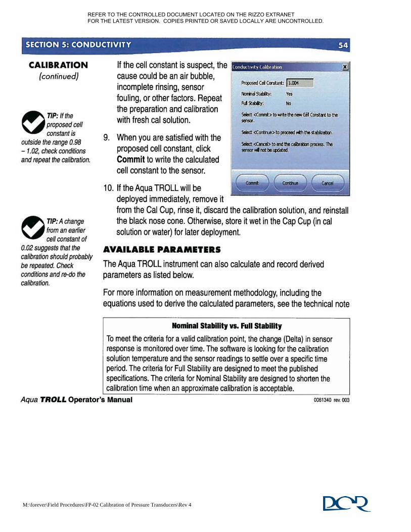
M:\forever\Field Procedures\FP-02 Calibration of Pressure Transducers\Rev 4
REFER TO THE CONTROLLED DOCUMENT LOCATED ON THE RIZZO EXTRANET FOR THE LATEST VERSION. COPIES PRINTED OR SAVED LOCALLY ARE UNCONTROLLED.

M:\forever\Field Procedures\FP-02 Calibration of Pressure Transducers\Rev 4
REFER TO THE CONTROLLED DOCUMENT LOCATED ON THE RIZZO EXTRANET FOR THE LATEST VERSION. COPIES PRINTED OR SAVED LOCALLY ARE UNCONTROLLED.

M:\forever\Field Procedures\FP-02 Calibration of Pressure Transducers\Rev 4
REFER TO THE CONTROLLED DOCUMENT LOCATED ON THE RIZZO EXTRANET FOR THE LATEST VERSION. COPIES PRINTED OR SAVED LOCALLY ARE UNCONTROLLED.

M:\forever\Field Procedures\FP-02 Calibration of Pressure Transducers\Rev 4
REFER TO THE CONTROLLED DOCUMENT LOCATED ON THE RIZZO EXTRANET FOR THE LATEST VERSION. COPIES PRINTED OR SAVED LOCALLY ARE UNCONTROLLED.

REFER TO THE CONTROLLED DOCUMENT LOCATED ON THE RIZZO EXTRANET FOR THE LATEST VERSION. COPIES PRINTED OR SAVED LOCALLY ARE UNCONTROLLED.

REFER TO THE CONTROLLED DOCUMENT LOCATED ON THE RIZZO EXTRANET FOR THE LATEST VERSION. COPIES PRINTED OR SAVED LOCALLY ARE UNCONTROLLED.

1 of 5 FP-3, Rev. 1
April 29, 2010
M:\forever\Field Procedures\FP-03 Field Calibration of Flo Mate Model 2000\Rev. 1
CALIBRATION OF FLO-MATE MODEL 2000
FP-3, REVISION 1
APRIL 29, 2010 1.0 TYPE OF EQUIPMENT
The Marsh-McBirney Model 2000 Flo-Mate is a portable flowmeter designed for use in both the field and the laboratory. The unit uses an electromagnetic sensor to measure the velocity in a conductive liquid such as water. The velocity is displayed on a digital display as feet per second (ft/s) or meters per second (m/s). The Model 2000 Flo-Mate measures flow using the Faraday law of electromagnetic induction. This law states that as a conductor moves through a magnetic field, a voltage is produced. The magnitude of this voltage is directly proportional to the velocity at which the conductor moves through the magnetic field. When the flow approaches the sensor from directly in front, then the direction of the flow, the magnetic field, and the sensed voltage are mutually perpendicular to each other. Hence, the voltage output will represent the velocity of the flow at the electrodes. The sensor is equipped with an electromagnetic coil that produces the magnetic field. A pair of carbon electrodes measures the voltage produced by the velocity of the conductor, which in this case is the flowing liquid. The measured voltage is processed by the electronics and output as a linear measurement of velocity. The Model 2000 Flo-Mate is used to measure flow velocity in streams. These measurements are used in conjunction with width and depth measurements at stream cross sections so that volume flow rate (discharge) can be estimated. Whether these estimates are part of a safety-related activity or not depends on the project-specific objectives. The project-specific requirements should be determined before the equipment is brought to the site, to determine the proper calibration and documentation required by the RIZZO Quality Assurance (QA) Program prior to equipment use. This procedure provides supporting field checks and calibrations that are required as part of this program.
2.0 REFERENCES 2.1 Marsh-McBirney, Inc., November 2000, “Model 2000 Installation and Operations
Manual.”
2.2 PCR Holdings, Inc., Health and Safety Manual.
REFER TO THE CONTROLLED DOCUMENT LOCATED ON THE RIZZO EXTRANET FOR THE LATEST VERSION. COPIES PRINTED OR SAVED LOCALLY ARE UNCONTROLLED.

2 of 5 FP-3, Rev. 1
April 29, 2010
M:\forever\Field Procedures\FP-03 Field Calibration of Flo Mate Model 2000\Rev. 1
2.3 RIZZO, QP-3, “Personnel Qualifications.”
2.4 RIZZO, QP-25, “Records Control.”
2.5 RIZZO, FP-18, “Calibration Records.” 3.0 REFERENCE STANDARD
When the Model 2000 Flo-Mate is submerged in a bucket of water and allowed to stabilize, the sensor should measure zero within ± 0.05 ft/sec.
4.0 FREQUENCY OF CALIBRATION
Prior to each setup of the Model 2000 Flo-Mate at a surface water location (stream, lake discharge, etc.), a field check of the calibration shall be performed and the instrument shall be zeroed. This field check shall not preclude the need for factory calibration of the unit on a 12-month schedule, as recommended by the manufacturer. This calibration shall be procured per the requirement of the RIZZO QA Program. Field personnel shall confirm that a factory calibration of the unit has been performed within the recommended interval, prior to initiation of field testing using the unit.
5.0 CALIBRATION METHOD AND SEQUENTIAL ACTIONS
Prior to beginning field activities, field personnel should review the site-specific Work Plan and/or Health and Safety Plan (if applicable) to determine if any relevant site-specific health and safety concerns exist. If no site-specific work plan and/or health and safety plan is in effect, work should be performed in accordance with the PCR Holdings, Inc. Health and Safety Manual.
5.1 Complete the initial information on an Equipment Calibration Log (found in
RIZZO Procedure FP-18) including the project name, project number, date, equipment make/type, model number, and serial/ID number. In the Calibration Procedure line, write the procedure number, revision, and date. In the Calibration or Calibration Check Description line, write “zero electronic drift.” In the Calibration Due Date line, record “next use.” It is not necessary to record information in the Reference Standard Information Table. Under the Reference Standard column, write “0.0 ft/sec.” Under the Acceptance Tolerance column, write the acceptable offset from zero as “± 0.05 ft/sec.”
The following steps zero the electromagnetic sensor to correct for electronic drift.
REFER TO THE CONTROLLED DOCUMENT LOCATED ON THE RIZZO EXTRANET FOR THE LATEST VERSION. COPIES PRINTED OR SAVED LOCALLY ARE UNCONTROLLED.

3 of 5 FP-3, Rev. 1
April 29, 2010
M:\forever\Field Procedures\FP-03 Field Calibration of Flo Mate Model 2000\Rev. 1
5.2 Zero Check: First clean the sensor, in accordance with manufacturer’s recommendations, as a thin film of oil on the electrodes can cause noisy readings. Then place the sensor in a plastic bucket of water. Keep it at least 3 inches away from the sides and bottom of the bucket. To make sure the water is not moving, wait 10 to 15 minutes after you have positioned the sensor before taking any zero readings. Use a filter value of 5 seconds. Record the reading in the Equipment Reading column.
5.3 Zero Adjust: Position the sensor as described in the zero check procedure.
5.2.1 To initiate the zero start sequence, press the STO and RCL keys at the same time. You will see the number 3 on the display.
5.2.2 Decrement to zero with the ↓ key.
5.2.3 The number 32 will be displayed.
5.2.4 The unit will decrement itself to zero and turn off. The unit is now zeroed.
5.4 Note: Each key in the zero adjust sequence must be pressed within 5 seconds of the previous key. If the time between key entries is longer than 5 seconds or if a wrong key is pressed, the unit will display an ERR 3. Turn the unit OFF then back ON and try again.
5.5 Since the drift is being calibrated to the reference standard, record “N/A” in the
Acceptance Tolerance column. Record that the calibration is accepted, unless there is an error message as described in Section 6.0 Limitations. If the unit cannot be zeroed successfully, then record that the calibration is failed. All personnel performing the zeroing of electronic drift should sign and date the form.
5.6 Equipment that fails calibration is tagged to indicate that it is out of calibration
and then segregated from calibrated equipment to prevent inadvertent use. Once this is done, the equipment should be slated to be returned to the manufacturer for repair.
6.0 LIMITATIONS
6.1 There are three error messages (#3, #4, and #5) displayed by the unit that are related to field calibration. See the “Model 2000 Installation and Operations Manual” for additional information related to error messages. 6.1.1 Error #3: Incorrect zero-adjust-start sequence. Reinitiate zero-adjust-
start sequence.
REFER TO THE CONTROLLED DOCUMENT LOCATED ON THE RIZZO EXTRANET FOR THE LATEST VERSION. COPIES PRINTED OR SAVED LOCALLY ARE UNCONTROLLED.

4 of 5 FP-3, Rev. 1
April 29, 2010
M:\forever\Field Procedures\FP-03 Field Calibration of Flo Mate Model 2000\Rev. 1
6.1.2 Error #4: Zero offset is greater than the zero adjust range. Repeat the zero-adjust procedure. If the error is still displayed, the unit needs servicing.
6.1.3 Error #5: Conductivity lost or noise detected during zero adjust. Usually caused by the sensor being out of the water.
6.2 Additional error messages displayed by the unit are:
6.2.1 Low Bat: Indicates low batteries. Replace the batteries.
6.2.2 Noise: Indicates excessive electrical noise is present in the flow which
will interfere with normal operation. This will cause the display to blank out. Note: The noise flag usually comes on for few a seconds after the sensor is submerged even though there is no noise present. This is normal.
6.2.3 Con Lost: Indicates that either the sensor electrodes are out of the water or they have become coated with oil or grease. After 5 minutes, the unit will turn itself OFF. If the electrodes are coated, clean them.
6.2.4 Error #1: Problem with sensor drive circuit. Check sensor disconnect.
6.2.5 Error #2: Memory full error. Memory must be cleared before another reading can be stored.
7.0 SUITABLE ENVIRONMENTAL CONDITIONS
The Model 2000 Flo-Mate can be used and calibrated in all weather conditions, within specified temperature ranges. The open-channel velocity sensor operates within a temperature range of 32°F to 160°F (0°C to 72°C) and the electronics function within a temperature range of 32°F to 122°F (0°C to 50°C).
8.0 PERSONNEL QUALIFICATIONS AND TRAINING REQUIREMENTS
The personnel performing calibration checks of the Model 2000 Flo-Mate shall be knowledgeable in the methodologies used and shall be qualified in accordance with RIZZO Procedure QP-3. Personnel performing the calibration checks are responsible for obtaining the necessary support and/or equipment required to perform the procedure.
REFER TO THE CONTROLLED DOCUMENT LOCATED ON THE RIZZO EXTRANET FOR THE LATEST VERSION. COPIES PRINTED OR SAVED LOCALLY ARE UNCONTROLLED.

5 of 5 FP-3, Rev. 1
April 29, 2010
M:\forever\Field Procedures\FP-03 Field Calibration of Flo Mate Model 2000\Rev. 1
9. 0 RECORD KEEPING
Field calibration of the equipment will be recorded on the RIZZO Equipment Calibration Log (RIZZO Procedure FP-18).
Completed Equipment Calibration Logs shall be properly stored according to requirements specified in RIZZO Procedure QP-25.
REFER TO THE CONTROLLED DOCUMENT LOCATED ON THE RIZZO EXTRANET FOR THE LATEST VERSION. COPIES PRINTED OR SAVED LOCALLY ARE UNCONTROLLED.

REFER TO THE CONTROLLED DOCUMENT LOCATED ON THE RIZZO EXTRANET FOR THE LATEST VERSION. COPIES PRINTED OR SAVED LOCALLY ARE UNCONTROLLED.

REFER TO THE CONTROLLED DOCUMENT LOCATED ON THE RIZZO EXTRANET FOR THE LATEST VERSION. COPIES PRINTED OR SAVED LOCALLY ARE UNCONTROLLED.

2 of 5 FP-4, Rev. 4
May 24, 2011
3.0 REFERENCE STANDARD
3.1 Conductivity, pH, ORP, DO, and Turbidity
The YSI 6920 V2-2 will be field calibrated with calibration solutions for conductivity, pH, ORP, and turbidity. The YSI 6920 V2-2 will be field calibrated for DO with tap water, as specified by the manufacturer of the unit.
3.2 Temperature
The YSI 6920 V2-2 temperature will be checked with a calibrated thermometer.
3.3 Atmospheric Pressure
The YSI 6920-V2-2 barometer reads true barometric pressure. The primary purpose of the YSI barometer is for use in calibration of DO. Therefore, a calibration check of atmospheric pressure is not a necessary requirement per the RIZZO QA Program. A single point calibration of atmospheric pressure is possible with the YSI unit; however, the manufacturer warns against this unless the reference standard is accurate. Weather service readings of atmospheric pressure are not true, because they are typically corrected to sea level and would need to be un-corrected for comparison to readings of the YSI barometer. A high quality lab barometer would be required to perform this calibration, but, as stated above, it is not necessary for the intended use of the equipment. Therefore, field personnel are specifically directed not to alter the atmospheric pressure setting in the setup menu of the instrument.
3.4 Procurement and Calibration of Reference Standards Reference standard calibration shall be procured per the requirements of the RIZZO QA Program. Calibration certificates shall contain the information required by the RIZZO QA Program.
REFER TO THE CONTROLLED DOCUMENT LOCATED ON THE RIZZO EXTRANET FOR THE LATEST VERSION. COPIES PRINTED OR SAVED LOCALLY ARE UNCONTROLLED.

3 of 5 FP-4, Rev. 4
May 24, 2011
4.0 FREQUENCY OF CALIBRATION
4.1 Conductivity, pH, ORP, DO, and Turbidity
The YSI 6920 V2-2 will be field calibrated on a weekly basis of ongoing use. If the unit has not been used for more than one week, it will be calibrated prior to its use.
4.2 Temperature
The temperature sensor will be checked a minimum of one time every 12 months.
4.3 RIZZO personnel shall confirm that a calibration of the unit (as described
in Sections 4.1 and 4.2) has been performed and that the calibration is current, prior to initiation of field testing with the unit.
5.0 CALIBRATION METHOD AND SEQUENTIAL ACTIONS
Prior to beginning field activities, field personnel should review the site-specific Work Plan and/or Health and Safety Plan (if applicable) to determine if any relevant site-specific health and safety concerns exist. If no site-specific work plan and/or health and safety plan is in effect, work should be performed in accordance with the PCR Holdings, Inc. Health and Safety Manual. Check the display/logger to determine the battery level to see if recharging or new batteries are necessary. Prior to calibration, all instrument probes on the sonde must be cleaned according to the manufacturer’s instructions. Failure to perform this step can lead to erratic measurements. The probes must be cleaned by rinsing with de-ionized water before and after immersion in a calibration solution. 5.1 Calibration of Conductivity, pH, ORP, DO, and Turbidity
5.1.1 Complete the initial information on an Equipment Calibration Log found in RIZZO Procedure FP-18, including the project name, project number, date, equipment make/type, model number, and serial/ID number.
5.1.2 Prepare to calibrate only the parameters that are required for the
intended use. In the Calibration Procedure line, write the procedure number, revision, and date. In the Calibration or Calibration Check Description line, write the parameters to be calibrated for the intended field activity. In the Calibration Due Date line, record one week from the calibration date. Record the
REFER TO THE CONTROLLED DOCUMENT LOCATED ON THE RIZZO EXTRANET FOR THE LATEST VERSION. COPIES PRINTED OR SAVED LOCALLY ARE UNCONTROLLED.

4 of 5 FP-4, Rev. 4
May 24, 2011
calibration solution information in the Reference Standard Information table.
5.1.3 Follow the calibration instructions for each parameter as described
in Section 2.6, Getting Ready to Calibrate, of the User Manual (Attachment A). Record the field calibration information for each parameter that is calibrated. Since the parameters are being calibrated to the reference standard, record “N/A” in the Acceptance Tolerance column. Record whether the calibrations are accepted or failed. All personnel performing the equipment calibration should sign and date the form.
5.2 Calibration of Temperature
5.2.1 Complete the initial information on an Equipment Calibration Log (RIZZO Procedure FP-18) including the project name, project number, date, equipment make/type, model number, and serial/ID number. In the Calibration Procedure line, write the procedure number, revision, and date. In the Calibration or Calibration Check Description line, write “temperature calibration check.” In the Calibration Due Date line, record one year from the calibration date. Record the thermometer information in the Reference Standard Information table.
5.2.2 Place the calibrated thermometer into a bucket of clean, cold water
(approximately 40°F to 50°F (4°C to 10°C). After the temperature has equilibrated on the thermometer, check to make sure the temperature of the water is within the operating range of the equipment as specified in Section 7.0 Suitable Environmental Conditions.
5.2.3 Place the YSI into the bucket and read the temperature. Let the
temperature equilibrate on both the thermometer and the YSI. Record the thermometer and YSI readings in the Reference Standard and Equipment Reading columns to the nearest 0.1°F (0.1°C), respectively. Record “± 2.0°F” (± 1.0°C) in the Acceptance Tolerance column and record whether the instrument check is accepted or failed.
5.2.4 Repeat Steps 5.2.2 and 5.2.3 with a bucket of clean, warm water
(approximately 70°F to 80°F (21°C to 27°C)). All personnel performing the temperature calibration check should sign and date the form.
REFER TO THE CONTROLLED DOCUMENT LOCATED ON THE RIZZO EXTRANET FOR THE LATEST VERSION. COPIES PRINTED OR SAVED LOCALLY ARE UNCONTROLLED.

5 of 5 FP-4, Rev. 4
May 24, 2011
6.0 LIMITATIONS
Limitations to calibration and recommended actions are described in Section 6, Troubleshooting, of the User Manual (Attachment B).
7.0 SUITABLE ENVIRONMENTAL CONDITIONS
The YSI 6920 V2-2 instrument can be used under most environmental conditions, i.e., those that are safe for field personnel. The operational temperature range is -5°C to 50°C. The barometer range is 500 to 800 millimeters of mercury (mm Hg).
8.0 PERSONNEL QUALIFICATIONS AND TRAINING REQUIREMENTS
The field personnel performing field calibration of the YSI shall be knowledgeable in the methodologies used and shall be qualified in accordance with RIZZO Procedure QP-3. Field personnel are responsible for obtaining the necessary support and/or equipment required to perform the procedure.
9.0 RECORD KEEPING
Field calibration of the equipment will be recorded on the RIZZO Equipment Calibration Log (RIZZO Procedure FP-18). Completed Equipment Calibration Logs shall be properly stored according to requirements specified in RIZZO Procedure QP-25.
REFER TO THE CONTROLLED DOCUMENT LOCATED ON THE RIZZO EXTRANET FOR THE LATEST VERSION. COPIES PRINTED OR SAVED LOCALLY ARE UNCONTROLLED.

ATTACHMENT A
6-SERIES MULTI-PARAMETER WATER QUALITY SONDES USER MANUAL
SECTION 2.6
REFER TO THE CONTROLLED DOCUMENT LOCATED ON THE RIZZO EXTRANET FOR THE LATEST VERSION. COPIES PRINTED OR SAVED LOCALLY ARE UNCONTROLLED.

REFER TO THE CONTROLLED DOCUMENT LOCATED ON THE RIZZO EXTRANET FOR THE LATEST VERSION. COPIES PRINTED OR SAVED LOCALLY ARE UNCONTROLLED.

REFER TO THE CONTROLLED DOCUMENT LOCATED ON THE RIZZO EXTRANET FOR THE LATEST VERSION. COPIES PRINTED OR SAVED LOCALLY ARE UNCONTROLLED.

REFER TO THE CONTROLLED DOCUMENT LOCATED ON THE RIZZO EXTRANET FOR THE LATEST VERSION. COPIES PRINTED OR SAVED LOCALLY ARE UNCONTROLLED.

REFER TO THE CONTROLLED DOCUMENT LOCATED ON THE RIZZO EXTRANET FOR THE LATEST VERSION. COPIES PRINTED OR SAVED LOCALLY ARE UNCONTROLLED.

REFER TO THE CONTROLLED DOCUMENT LOCATED ON THE RIZZO EXTRANET FOR THE LATEST VERSION. COPIES PRINTED OR SAVED LOCALLY ARE UNCONTROLLED.

REFER TO THE CONTROLLED DOCUMENT LOCATED ON THE RIZZO EXTRANET FOR THE LATEST VERSION. COPIES PRINTED OR SAVED LOCALLY ARE UNCONTROLLED.

REFER TO THE CONTROLLED DOCUMENT LOCATED ON THE RIZZO EXTRANET FOR THE LATEST VERSION. COPIES PRINTED OR SAVED LOCALLY ARE UNCONTROLLED.

REFER TO THE CONTROLLED DOCUMENT LOCATED ON THE RIZZO EXTRANET FOR THE LATEST VERSION. COPIES PRINTED OR SAVED LOCALLY ARE UNCONTROLLED.

REFER TO THE CONTROLLED DOCUMENT LOCATED ON THE RIZZO EXTRANET FOR THE LATEST VERSION. COPIES PRINTED OR SAVED LOCALLY ARE UNCONTROLLED.

REFER TO THE CONTROLLED DOCUMENT LOCATED ON THE RIZZO EXTRANET FOR THE LATEST VERSION. COPIES PRINTED OR SAVED LOCALLY ARE UNCONTROLLED.
REFER TO THE CONTROLLED DOCUMENT LOCATED ON THE RIZZO EXTRANET FOR THE LATEST VERSION. COPIES PRINTED OR SAVED LOCALLY ARE UNCONTROLLED.

REFER TO THE CONTROLLED DOCUMENT LOCATED ON THE RIZZO EXTRANET FOR THE LATEST VERSION. COPIES PRINTED OR SAVED LOCALLY ARE UNCONTROLLED.

REFER TO THE CONTROLLED DOCUMENT LOCATED ON THE RIZZO EXTRANET FOR THE LATEST VERSION. COPIES PRINTED OR SAVED LOCALLY ARE UNCONTROLLED.

REFER TO THE CONTROLLED DOCUMENT LOCATED ON THE RIZZO EXTRANET FOR THE LATEST VERSION. COPIES PRINTED OR SAVED LOCALLY ARE UNCONTROLLED.

REFER TO THE CONTROLLED DOCUMENT LOCATED ON THE RIZZO EXTRANET FOR THE LATEST VERSION. COPIES PRINTED OR SAVED LOCALLY ARE UNCONTROLLED.

REFER TO THE CONTROLLED DOCUMENT LOCATED ON THE RIZZO EXTRANET FOR THE LATEST VERSION. COPIES PRINTED OR SAVED LOCALLY ARE UNCONTROLLED.

REFER TO THE CONTROLLED DOCUMENT LOCATED ON THE RIZZO EXTRANET FOR THE LATEST VERSION. COPIES PRINTED OR SAVED LOCALLY ARE UNCONTROLLED.

REFER TO THE CONTROLLED DOCUMENT LOCATED ON THE RIZZO EXTRANET FOR THE LATEST VERSION. COPIES PRINTED OR SAVED LOCALLY ARE UNCONTROLLED.

REFER TO THE CONTROLLED DOCUMENT LOCATED ON THE RIZZO EXTRANET FOR THE LATEST VERSION. COPIES PRINTED OR SAVED LOCALLY ARE UNCONTROLLED.

REFER TO THE CONTROLLED DOCUMENT LOCATED ON THE RIZZO EXTRANET FOR THE LATEST VERSION. COPIES PRINTED OR SAVED LOCALLY ARE UNCONTROLLED.

REFER TO THE CONTROLLED DOCUMENT LOCATED ON THE RIZZO EXTRANET FOR THE LATEST VERSION. COPIES PRINTED OR SAVED LOCALLY ARE UNCONTROLLED.

REFER TO THE CONTROLLED DOCUMENT LOCATED ON THE RIZZO EXTRANET FOR THE LATEST VERSION. COPIES PRINTED OR SAVED LOCALLY ARE UNCONTROLLED.

REFER TO THE CONTROLLED DOCUMENT LOCATED ON THE RIZZO EXTRANET FOR THE LATEST VERSION. COPIES PRINTED OR SAVED LOCALLY ARE UNCONTROLLED.

REFER TO THE CONTROLLED DOCUMENT LOCATED ON THE RIZZO EXTRANET FOR THE LATEST VERSION. COPIES PRINTED OR SAVED LOCALLY ARE UNCONTROLLED.

REFER TO THE CONTROLLED DOCUMENT LOCATED ON THE RIZZO EXTRANET FOR THE LATEST VERSION. COPIES PRINTED OR SAVED LOCALLY ARE UNCONTROLLED.

REFER TO THE CONTROLLED DOCUMENT LOCATED ON THE RIZZO EXTRANET FOR THE LATEST VERSION. COPIES PRINTED OR SAVED LOCALLY ARE UNCONTROLLED.

ATTACHMENT B
6-SERIES MULTI-PARAMETER WATER QUALITY SONDES USER MANUAL
SECTION 6
REFER TO THE CONTROLLED DOCUMENT LOCATED ON THE RIZZO EXTRANET FOR THE LATEST VERSION. COPIES PRINTED OR SAVED LOCALLY ARE UNCONTROLLED.

REFER TO THE CONTROLLED DOCUMENT LOCATED ON THE RIZZO EXTRANET FOR THE LATEST VERSION. COPIES PRINTED OR SAVED LOCALLY ARE UNCONTROLLED.

REFER TO THE CONTROLLED DOCUMENT LOCATED ON THE RIZZO EXTRANET FOR THE LATEST VERSION. COPIES PRINTED OR SAVED LOCALLY ARE UNCONTROLLED.
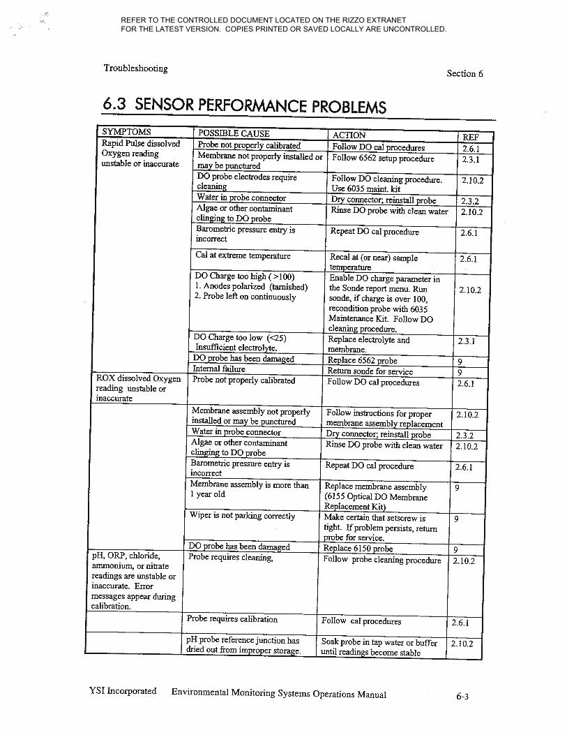
REFER TO THE CONTROLLED DOCUMENT LOCATED ON THE RIZZO EXTRANET FOR THE LATEST VERSION. COPIES PRINTED OR SAVED LOCALLY ARE UNCONTROLLED.

REFER TO THE CONTROLLED DOCUMENT LOCATED ON THE RIZZO EXTRANET FOR THE LATEST VERSION. COPIES PRINTED OR SAVED LOCALLY ARE UNCONTROLLED.

REFER TO THE CONTROLLED DOCUMENT LOCATED ON THE RIZZO EXTRANET FOR THE LATEST VERSION. COPIES PRINTED OR SAVED LOCALLY ARE UNCONTROLLED.

REFER TO THE CONTROLLED DOCUMENT LOCATED ON THE RIZZO EXTRANET FOR THE LATEST VERSION. COPIES PRINTED OR SAVED LOCALLY ARE UNCONTROLLED.

Page 1 of 11 FP-5, Rev. 1
May 25, 2011
PROCEDURE FOR MONITORING WELL INSTALLATION
FP-5, REVISION 1
MAY 25, 2011 1.0 OBJECTIVE AND SCOPE
This Procedure provides general guidance and information regarding the proper design and construction of groundwater monitoring wells. The methods described may be modified by project-specific requirements for monitoring well construction. In addition, many regulatory agencies have specific regulations pertaining to monitoring well construction and permitting. These requirements must be determined during the project planning phases of the investigation, and any required permits must be obtained before field work begins.
2.0 REFERENCES
2.1 American Society for Testing and Materials (ASTM), 2004, “Standard Practice for Design and Installation of Ground Water Monitoring Wells,” Method D 5092-03, June 2004.
2.2 Form FP-5-1, “Monitoring Well Installation Form.”
2.3 PCR Holdings, Inc., Health and Safety Manual.
2.4 RIZZO, FP-6, “Groundwater Monitoring Well Development.”
2.5 RIZZO, QP-3, “Personnel Qualifications.”
2.6 RIZZO, QP-25, “Records Control.” 3.0 TERMS AND DEFINITIONS
3.1 Annular Space, Annulus, or Well Annulus – The space between the well casing and borehole wall, or between two concentric casings.
3.2 Annular Seal – Low-permeability seal placed in the well annulus between the top of the filter pack seal and ground surface. The annular seal is composed of cement-bentonite grout.
REFER TO THE CONTROLLED DOCUMENT LOCATED ON THE RIZZO EXTRANET FOR THE LATEST VERSION. COPIES PRINTED OR SAVED LOCALLY ARE UNCONTROLLED.

Page 2 of 11 FP-5, Rev. 1
May 25, 2011
3.3 Borehole – A circular opening or uncased subsurface hole, deeper than it is wide, created by drilling for the purpose of installing a well or obtaining geologic, hydrogeologic, geotechnical, or geophysical data.
3.4 Bridge – An obstruction in the annular space that may prevent proper emplacement of filter pack, filter pack seal, or annular seal.
3.5 Casing – Impervious, durable pipe that is installed temporarily or permanently in a borehole to counteract caving, to advance the borehole, or to hydraulically isolate the zone being monitored.
3.6 Cement-Bentonite Grout – A mixture of bentonite, cement, and water, which is used as an annular or borehole sealant. The grout forms a semi-rigid low-permeability seal that prevents movement of fluid in the annular space or borehole and maintains the alignment of the casing in the borehole. This grout is composed of one 94-pound bag of Portland cement, 3 to 8 percent (by dry weight) of bentonite, and 6 gallons of water, according to ASTM D 5092-03.
3.7 Filter Pack – Sand or gravel installed in the annular space between the borehole wall and the well screen for the purpose of retaining and stabilizing the screened formation, and supporting the filter pack seal and the annular seal. It may also be referred to as the primary filter pack if a secondary filter pack is utilized during well installation.
3.8 Filter Pack Seal – Low-permeability seal placed in the well annulus between the top of the filter pack and the bottom of the annular seal.
3.9 Secondary Filter Pack – A second filter pack installed directly on top of the
primary filter pack. It is sometimes used to prevent the infiltration of filter pack seal material into filter pack zone.
3.10 Surge – An action causing water to move rapidly in and out of the well screen, thereby mobilizing and removing fine material from the surrounding filter pack and water-bearing formation.
3.11 Tremie Pipe – A pipe or hose placed in the bottom of the borehole and then subsequently moved upwards; used for emplacement of well construction materials (e.g., filter pack or grout slurry) into an annular space or borehole.
3.12 Well Screen – A filtering device which permits water to enter the well while retaining the filter pack in the well annulus; usually a cylindrical pipe with openings of uniform width, orientation, and spacing. A well screen is usually constructed of Polyvinyl chloride (PVC) or stainless steel.
REFER TO THE CONTROLLED DOCUMENT LOCATED ON THE RIZZO EXTRANET FOR THE LATEST VERSION. COPIES PRINTED OR SAVED LOCALLY ARE UNCONTROLLED.

Page 3 of 11 FP-5, Rev. 1
May 25, 2011
4.0 EQUIPMENT
Below is a list of items that may be needed when installing a monitoring well:
Personal protective equipment (PPE) (hard hats, safety glasses, etc.), as required by the site-specific Health and Safety Plan (HASP) and/or the corporate Health and Safety Officer.
Well drilling and installation equipment with associated materials (typically supplied by the driller).
Miscellaneous equipment (weighted engineer's tape, water level indicator, retractable engineers rule, electronic calculator, clipboard, appropriate field forms, and paint and/or ink marker for marking monitoring wells, as appropriate).
5.0 CALIBRATION REQUIREMENTS
Monitoring well installation utilizes no equipment with calibration requirements. 6.0 PROCEDURES
Prior to beginning field activities, field personnel should review the site-specific Work Plan and/or Health and Safety Plan (if applicable) to determine if any relevant site-specific health and safety concerns exist or procedures are to be followed. If no site-specific Work Plan and/or Health and Safety Plan is in effect, work should be performed in accordance with the PCR Holdings, Inc. Health and Safety Manual. Field personnel will monitor well installation activities and recommend changes in the methodology should unanticipated field conditions be encountered.
6.1 Types of Wells
There are two decisions that will dictate the type of well design to be utilized for monitoring well construction. The decision to complete the top of the well as an above-ground versus a flush-mount well and the decision to leave the borehole open hole versus utilizing a screened well result in the four possible well configurations:
Above-ground, open hole
Above-ground, screened well
Flush-mount, open hole
Flush mount, screened well
REFER TO THE CONTROLLED DOCUMENT LOCATED ON THE RIZZO EXTRANET FOR THE LATEST VERSION. COPIES PRINTED OR SAVED LOCALLY ARE UNCONTROLLED.

Page 4 of 11 FP-5, Rev. 1
May 25, 2011
Above-ground wells are usually designed with a stick-up of approximately 3 feet (ft) above ground surface elevation. In heavily trafficked regions, or areas where a stick-up casing is impractical, it may be necessary to install a “flush mount” well. Flush mount wells have the top of the riser set just below ground surface in a water-proof well vault. When installing the flush mount well, the riser must be covered securely with a watertight cap. The well shall be set in a protective enclosure sufficiently strong enough to permit traffic over the well with no subsequent damage. When installing a well in consolidated bedrock, a well screen may not be necessary and the well can be completed as open hole. This is only possible when the bedrock in question is competent and little potential exists for cave-in of the well. When constructing an open hole well, it is necessary to install and seal the upper portion of the borehole with casing in order to prevent downward movement of water along the annulus. The open hole portion of the well is thus used to monitor only the geologic materials that are adjacent to the open hole interval of rock.
6.2 System Design
The objectives and intended use for each monitoring well within the network should be clearly defined before the well drilling/installation activities are initiated. Within the monitoring system, different monitoring wells may serve different purposes and, therefore, require different depths, types of construction, and/or screen lengths. These design decisions should be explained in the project-specific work plan. Any changes made in the field should bear in mind the specific objectives for the affected well(s) and the overall monitoring network. The objectives for installing the monitoring wells may include, but are not limited to:
Determining groundwater flow directions and velocities.
Determining hydraulic properties of the geologic materials present at the site (e.g., hydraulic conductivity).
Sampling and characterizing natural groundwater chemistry.
Monitoring for contaminants in groundwater.
REFER TO THE CONTROLLED DOCUMENT LOCATED ON THE RIZZO EXTRANET FOR THE LATEST VERSION. COPIES PRINTED OR SAVED LOCALLY ARE UNCONTROLLED.

Page 5 of 11 FP-5, Rev. 1
May 25, 2011
6.3 Materials
The specifications for well design and construction will be part of the project-specific Work Plan. If site conditions require or warrant a deviation from the Work Plan, the actions taken and the reasons for it must be documented per the change management provisions provided in the Work Plan.
6.4 Well Depth, Diameter, and Monitored Interval
The well depth, diameter, and monitored interval must be tailored to the specific monitoring needs of each investigation. Specification of these items generally depends on the purpose of the monitoring system and the characteristics of the hydrogeologic zone being monitored. Wells of different depth, diameter, and monitored interval can be employed in the same groundwater monitoring system. The selection of the locations and depth intervals to be monitored might be based on some or all of the information cited below:
The depth, thickness, and uniformity of the water bearing zones being
investigated.
Spatial variation of properties and groundwater levels to assist with determining horizontal or vertical gradient(s).
Potential fluctuation in groundwater levels due to pumping, tidal effect, or other natural variations.
The source and spatial distribution of any contaminants or suspected contaminants.
The analysis of existing borehole geophysical logs, packer tests, and other available data.
Well diameter depends upon the hydraulic characteristics of the water-bearing zone as well as:
Site-specific sampling or testing requirements
Drilling method to be utilized
Depth of zone to be monitored
6.5 Riser Pipe and Screen Materials
Well materials are distinguished by pipe and screen composition, thickness of pipe, inside diameter, type of connection, and slot size (for well screen only). The most common types of material used for riser pipe are black carbon steel and PVC. Pipe thickness is referred to as Schedule and is usually found as Schedule 40 (thin wall) or Schedule 80 (thick wall). Monitoring wells are most commonly
REFER TO THE CONTROLLED DOCUMENT LOCATED ON THE RIZZO EXTRANET FOR THE LATEST VERSION. COPIES PRINTED OR SAVED LOCALLY ARE UNCONTROLLED.

Page 6 of 11 FP-5, Rev. 1
May 25, 2011
installed using Schedule 40 (standard strength thickness) pipe. PVC is the preferred material for well construction due to its wide availability, light weight, and low cost. Both PVC and stainless steel screens can be obtained with threaded, flush joints, which are preferable for use in monitoring wells. Glue or other solvents should not be used during installation of monitoring wells.
Placing a well in unconsolidated materials (such as sand, gravel, or silt) requires a well screen. The slot size of the screen and the grade of sand or gravel in the filter pack is dependent on the grain size of the geologic materials in which the well is being screened. The slot size should be selected to pass no more than 10 percent of the filter pack material into the well.
6.6 Annular Materials for Conventional Monitoring Wells
For screened monitoring wells, materials placed within the annular space around the riser pipe generally include a filter pack, a filter pack seal, and a cement-bentonite grout (the annular seal). The filter pack is usually a medium- to coarse-grained, well-sorted silica sand. The filter pack material should be selected to:
Minimize the amount of fine-grained sediment that can enter the well.
Allow the maximum rate of groundwater and inflow into the well.
Not affect the chemistry of water samples taken from the well.
In some cases, it may be desirable to place a secondary filter pack directly on top of the primary filter pack. If utilizing a secondary filter pack, it is important to make sure that the material is compatible with the primary filter pack. Additionally, it is important to keep the secondary filter a larger grain size to prevent the secondary material from invading the primary filter pack. The filter pack seal is frequently comprised of bentonite chips or pellets. The bentonite expands when hydrated and provides a seal between the screened interval and the overlying portion of the annular space, as well as any overlying hydrogeologic zones. The remainder of the annulus should be filled with a cement-bentonite grout. Grout is a general term referring to the solidified material installed above the filter pack seal and is composed according to the guidelines set forth in Section 3.6 of this Procedure. Depending on the characteristics of the bedrock, a monitoring well can be completed open hole. This should only be done in competent bedrock.
REFER TO THE CONTROLLED DOCUMENT LOCATED ON THE RIZZO EXTRANET FOR THE LATEST VERSION. COPIES PRINTED OR SAVED LOCALLY ARE UNCONTROLLED.

Page 7 of 11 FP-5, Rev. 1
May 25, 2011
6.7 Well Installation Activities
6.7.1 Drilling Equipment Cleaning and Decontamination
Drill rigs and drilling equipment should be clean and free of contaminants before arriving at the work site. Drilling equipment should be cleaned again between each borehole. Special procedures (e.g., steam-cleaning) may be required for some sites; such special procedures will be described in the site-specific Work Plan.
6.7.2 Utility Clearance
A utility survey should be completed prior to any drilling activity. This may include contacting local utility companies and utilizing a portable utility detector to determine the presence of any utility lines. All boreholes need to be cleared to a minimum depth of 4 ft or until encountering top of rock. Borings located in the vicinity of underground storage tanks (UST), integral piping, or underground utility lines may require the borehole clearing to be advanced to a deeper depth before starting normal drilling activities.
The size of the area for the utility clearance should be at least 20 ft in radius. Special caution should be taken for borings or wells located within 20 ft of power lines. If a monitoring well is needed within 20 ft of a power line, special precautions with the appropriate power company (such as de-energizing or grounding the line) may be necessary to prevent arcing from the power lines to the drill rig.
6.7.3 Drilling Activities
During drilling, it is important for the RIZZO field personnel to record details of the drilling process. Field personnel should note any variations from the project-specific work plan in addition to any unexpected conditions that could affect the well. All information should be recorded on the boring log. During drilling, care should be taken to prevent damage or clogging to the permeable zone to be monitored.
6.7.4 Screen and Riser Installation
Materials needed to construct a well should be at the well site and must be inspected prior to starting well construction. Pipe should be inspected to ensure that it is clean and there are no breaks in the riser pipe or screen. Well riser pipe should be cleaned, if necessary. There should be no bent pipe or pipe with cracks or dents.
REFER TO THE CONTROLLED DOCUMENT LOCATED ON THE RIZZO EXTRANET FOR THE LATEST VERSION. COPIES PRINTED OR SAVED LOCALLY ARE UNCONTROLLED.

Page 8 of 11 FP-5, Rev. 1
May 25, 2011
The screen should have a cap placed on the bottom, be measured for length, and then lowered slowly into the borehole. Care should be taken to keep the screen and riser centered within the borehole. If well riser pipe and screen are installed within hollow stem augers, no action is required; otherwise, centralizers can be placed at the top of the well screen and additionally every 20 to 40 ft for the remainder of the riser pipe. The riser should be secure at all times to avoid risk of being dropped and lost in the borehole. The RIZZO field personnel should carefully keep track of the length of all screen and casing lowered into the borehole during installation to verify that the screen is placed at the correct depth and to verify the total depth of the well. Borehole collapse may make it necessary to remove the screen and riser and clean out the borehole before reattempting to construct the well to the targeted depth. Riser pipe should be cut so that approximately 3 ft is sticking up above the ground surface. The riser should then be capped to prevent dirt or foreign objects entering the well during the remainder of the well installation process. The RIZZO personnel observing the well installation activities should record all appropriate information on Form FP-5-1. Care should be taken to completely fill in the form; leaving any field blank is unacceptable.
6.7.5 Filter Pack Installation
Once the screen and riser are in place, the filter pack material should be installed. Under no circumstances should the filter pack extend into multiple permeable zones. A weighted engineers’ tape or other method should be used to monitor the progress of the filter pack installation. Care should be taken to keep the measuring device elevated and to prevent the tape from becoming tangled with centralizers or buried by filter pack material.
6.7.6 Installation of Filter Pack Seal
The annular seal is typically composed of bentonite chips or pellets and should be installed directly above the filter pack. It should be approximately 2 to 3 ft thick, and the bottom of the seal should be at least 2 to 3 ft above the well screen. If formation water is limited in the vicinity of the seal, a small amount of deionized water or potable water should be added to the well annulus to properly hydrate the seal. Field personnel should note the volume of water added in the remarks section on Form FP-5-1. Sufficient time is required to allow the seal to fully hydrate and expand to properly seal off the well, prior to continuing with installation of the well. This timeframe is dependent upon the material being utilized
REFER TO THE CONTROLLED DOCUMENT LOCATED ON THE RIZZO EXTRANET FOR THE LATEST VERSION. COPIES PRINTED OR SAVED LOCALLY ARE UNCONTROLLED.

Page 9 of 11 FP-5, Rev. 1
May 25, 2011
for the well and can vary from 30 to 60 minutes. This information should be determined prior to the seal installation. The filter pack should extend at least 3 ft above the top of the screened interval. If bridging of the filter pack material is suspected, the filter pack may need to be developed immediately following placement of the filter pack, utilizing a surge block. Surging may eliminate any bridging of the filter pack materials that may have occurred during installation of the filter pack. The development procedures are covered in RIZZO Procedure FP-6, “Groundwater Monitoring Well Development.” Failure to allow the bentonite to hydrate can result in grout entering the screened interval. For shallow borings (< 10 ft), it is possible to avoid grouting to the surface and to simply install the filter pack seal to ground surface.
6.7.7 Annular Seal Installation
Cement-bentonite grout should be mixed as described in Section 3.6. The necessary volume of grout needed to complete a well can be calculated by subtracting the volume of the well casing from the overall volume of the borehole. Additional grout should be mixed to account for any of the grout lost within the formation due to grout seeping into fractures or permeable formation sidewalls or displacement when the tremie pipe is removed. The water and cement should be mixed first, and the bentonite added to the cement slurry. This slurry should then be pumped into the well using a side discharge tremie pipe to avoid any bridging or washing out of previously installed annular materials. Continue grouting until the grout at the top of the borehole is similar in consistency to the grout being pumped into the well. Remove the tremie pipe and top off the annular space. The grout will settle over a 24-hour period. This open annulus should be filled in with cement when the concrete pad is constructed, as described in Section 6.8.
6.7.8 Protective Casing
Upon completion of a stick-up monitoring well, a protective outer casing with a hinged or removable locking cap is typically placed over the top of the well. The casing should be of sufficient size to fit comfortably over the riser and extend at least 2 inches (in.) into the ground. The top of the riser should be almost level with the top of the protective casing and must be easily accessible. The protective casing should have a weep hole installed approximately 2 in. above the well pad surface to allow the
REFER TO THE CONTROLLED DOCUMENT LOCATED ON THE RIZZO EXTRANET FOR THE LATEST VERSION. COPIES PRINTED OR SAVED LOCALLY ARE UNCONTROLLED.

Page 10 of 11 FP-5, Rev. 1
May 25, 2011
draining of any water that may enter the above-ground portion of the well annulus. Coarse material should be installed within this portion of the well annulus up to a level near the top of riser. The outer protective casing should be clearly and permanently labeled with the well identification information.
6.8 Well Completion
A concrete pad should be installed at the ground surface to protect the integrity of the well. The concrete pad should measure approximately 2 ft wide by 2 ft long by 6 in. thick and should slope away from the well. Three to four protective bollards should be installed around the well or well cluster to aid in protection and visibility. These bollards should be at least 5 ft tall and painted in a bright color. The bottom 2 to 2.5 ft of the bollards should be secured in cement in the ground. In highly trafficked locations, it is advisable to attach reflective markings or tape to the bollards and well casing. For a flush-mount well, the riser will need to be cut slightly below ground surface elevation prior to completing the well. A protective enclosure (e.g., road box) shall surround the well and be cemented into the ground. This will provide sufficient fortification to prevent damage from vehicles or other surface traffic.
6.9 Monitoring Well Installation Field Form (Form FP-5-1)
6.9.1 RIZZO personnel observing the field activities should fill out Form FP-5-1 completely and accurately, including their signature and date on the designated line following completion of each activity (i.e., well installation and completion).
6.9.2 An approving reviewer (checker) must sign the completed field form on
the designated line. This signature certifies that the documentation on the field form has been reviewed and indicates that the techniques utilized met those outlined in this field procedure.
7.0 SUITABLE ENVIRONMENTAL CONDITIONS
Monitoring well installation can be performed in all weather conditions, with the exception of significant precipitation events and lightning storms. Site-specific work plans and/or site-specific Health and Safety Plans should be reviewed prior to all field excursions for health and safety protocols associated with environmental conditions such as accidental spills, construction activities, and the presence of potentially harmful contaminants.
REFER TO THE CONTROLLED DOCUMENT LOCATED ON THE RIZZO EXTRANET FOR THE LATEST VERSION. COPIES PRINTED OR SAVED LOCALLY ARE UNCONTROLLED.

Page 11 of 11 FP-5, Rev. 1
May 25, 2011
8.0 PERSONNEL QUALIFICATIONS AND TRAINING REQUIREMENTS
The field personnel responsible for well development and the approving reviewer (checker) shall be knowledgeable in the methodologies used and shall be qualified in accordance with RIZZO Procedure QP-3. Field personnel are responsible for obtaining the necessary support and/or equipment required to perform the procedure.
9.0 RECORDKEEPING
9.1 Information and data collected during well development will be recorded on Form FP-5-1.
9.2 Digital photography should be used to document the field activity. Photos of well construction, the construction site, and conditions around the site should be properly labeled by field personnel and archived according to the site-specific work plan.
9.3 Photographs, field activity daily logs, and completed field forms should be collected at the end of each day and properly stored, according to requirements specified in RIZZO Procedure QP-25.
REFER TO THE CONTROLLED DOCUMENT LOCATED ON THE RIZZO EXTRANET FOR THE LATEST VERSION. COPIES PRINTED OR SAVED LOCALLY ARE UNCONTROLLED.

Project Name: Installed By: Date:
Project Number: Date(s) of Well Installation:
BOREHOLE INFORMATION
Boring Number: Borehole Diameter: ( )1
Date of Boring Completion:
MONITOR WELL DESCRIPTION
Screen Material: Riser Pipe Material:
Screen Diameters: Riser Pipe Diameters:
Outer: ( )1 Inner: ( )1 Outer: ( )1 Inner: ( )1
Length of Screen: ( )1 Length of Pipe Sections: ( )1
Schedule: Schedule:
Slot Size: ( )1 Joining Method:
Top of Riser Pipe
Protective Casing Top: Bottom:
Grout Top: Bottom:
Bentonite Top: Bottom:
Filter-Pack Material2: Top: Bottom:
Riser Pipe Top: Bottom:
Screened Section Top: Bottom:
Piezometer/Well Tip (Bottom)
Borehole (Bottom)
Installation Sections Completed By:
Signed Date
PROTECTIVE SYSTEM
Protective Casing Length: ( )1 Bollards: Number: Diameter: ( )1
Protective Casing O.D.: ( )1 Above Ground Length: ( )1
Below Ground Length: ( )1
Other Protection:
Protective System Sections Completed By:
Signed Date
Remarks:
Approving Reviewer (Checker) Signature Date1 Specify Units of Measure2 Specify Filter-Pack Material
FP-5-1, Rev. 1, 5/25/11
WELL NO:
MONITORING WELL INSTALLATION FORM
ITEMDISTANCE ABOVE/BELOW GROUND
SURFACE ( ) - UNITSNOTES
REFER TO THE CONTROLLED DOCUMENT LOCATED ON THE RIZZO EXTRANET FOR THE LATEST VERSION. COPIES PRINTED OR SAVED LOCALLY ARE UNCONTROLLED.

REFER TO THE CONTROLLED DOCUMENT LOCATED ON THE RIZZO EXTRANET FOR THE LATEST VERSION. COPIES PRINTED OR SAVED LOCALLY ARE UNCONTROLLED.

REFER TO THE CONTROLLED DOCUMENT LOCATED ON THE RIZZO EXTRANET FOR THE LATEST VERSION. COPIES PRINTED OR SAVED LOCALLY ARE UNCONTROLLED.

Page 1 of 9 FP-6, Rev. 2
May 25, 2011
GROUNDWATER MONITORING WELL DEVELOPMENT PAUL C. RIZZO ASSOCIATES, INC.
FP-6, REVISION 2
MAY 25, 2011 1.0 OBJECTIVE AND SCOPE
Well development is important as a means to stabilize and increase the permeability of the filter pack around the well screen, to remove fine-grained sediment from the well that may have entered during or after well construction, and to restore any of the porosity and permeability of the formation, which may have been reduced by drilling operations. A monitoring well must be properly developed to provide representative data for the geologic unit being characterized. The selection of the well development method is based on:
Drilling method
Diameter and total depth of well
Well construction details
Static depth to groundwater
Hydraulic conductivity characteristics of the aquifer
This procedure provides a description of acceptable well development methods, equipment necessary for performing well development, and the steps and documentation required for completing well development.
2.0 REFERENCES
2.1 American Society for Testing and Materials (ASTM), 2004, “Standard Practice for Design and Installation of Ground Water Monitoring Wells,” Method D 5092-03, June 2004.
2.2 Form FP-6-1, “Well Development Form.”
2.3 PCR Holdings, Inc., Health and Safety Manual.
2.4 RIZZO, Quality Assurance Manual.
2.5 RIZZO, QP-2, “Work Plan Preparation.”
2.6 RIZZO, QP-3, “Personnel Qualifications.”
REFER TO THE CONTROLLED DOCUMENT LOCATED ON THE RIZZO EXTRANET FOR THE LATEST VERSION. COPIES PRINTED OR SAVED LOCALLY ARE UNCONTROLLED.

Page 2 of 9 FP-6, Rev. 2
May 25, 2011
2.7 RIZZO, FP-17, “Calibration of Buckets and Drums.”
2.8 RIZZO, QP-25, “Records Control.”
3.0 TERMS AND DEFINITIONS
3.1 Annular Space, Annulus, or Well Annulus – The space between the well casing and borehole wall, or between two concentric casings.
3.2 Annular Seal – Low-permeability seal placed in the well annulus between the top of the filter pack seal and ground surface. Typically, the annular seal is composed of cement-bentonite grout.
3.3 Bailer – A hollow tube used for removing water and suspended sediments from a well.
3.4 Bentonite Chips – Irregular shaped pieces of high swelling sodium bentonite clay used for installing the filter pack seal.
3.5 Bentonite Pellets – Pre-formed, compressed pellets made from high swelling sodium bentonite. The pellets are compressed and will swell to a greater volume than bentonite chips. Pellets are less likely to bridge or hang up in the well than bentonite chips.
3.6 Borehole – A circular opening or uncased subsurface hole, deeper than it is wide, created by drilling for the purpose of installing a well or obtaining geologic, hydrogeologic, geotechnical, or geophysical data.
3.7 Bridge – An obstruction in the annular space that may prevent proper emplacement of filter pack, filter pack seal, or annular seal.
3.8 Casing – Impervious, durable pipe that is installed temporarily or permanently in a borehole to counteract caving, to advance the borehole, or to hydraulically isolate the zone being monitored.
3.9 Cement-Bentonite Grout – A mixture of bentonite, cement, and water used as an annular or borehole sealant. The grout forms a semi-rigid low-permeability seal that prevents movement of fluids in the annular space or borehole and maintains the alignment of the casing in the borehole. This grout is composed of one 94-pound bag of Portland cement, 3 to 8 percent (by dry weight) of bentonite, and 6 gallons of water according to ASTM D5092-04.
REFER TO THE CONTROLLED DOCUMENT LOCATED ON THE RIZZO EXTRANET FOR THE LATEST VERSION. COPIES PRINTED OR SAVED LOCALLY ARE UNCONTROLLED.

Page 3 of 9 FP-6, Rev. 2
May 25, 2011
3.10 Filter Pack – Sand or gravel installed in the annular space between the borehole wall and the well screen for the purpose of retaining and stabilizing the screened formation, and supporting the filter pack seal and the annular seal.
3.11 Filter Pack Seal – Low-permeability seal placed in the well annulus between the top of the filter pack and the bottom of the annular seal.
3.12 HASP – Health and Safety Plan. The HASP describes the method used to protect the safety, health, and welfare of people engaged in work or employment on a project. If a site-specific HASP does not exist for the project, then work should be performed in accordance with the PCR Holdings, Inc. Health and Safety Manual.
3.13 Jetting – Jetting involves lowering a small diameter pipe into the well and injecting a high-velocity horizontal stream of water or air through the pipe into the screen openings. This method is especially effective at breaking down filter cakes developed during mud rotary drilling. Simultaneous air-lift pumping is usually used to remove fines.
3.14 Submersible Pump – A pump designed to be placed in the well and to pump water up and out of the well.
3.15 Surge – An action causing water to move rapidly in and out of the well screen, thereby mobilizing and removing fine material from the surrounding filter pack and water-bearing formation.
3.16 Surge Block – Flat seal that closely fits the casing interior and is operated like a plunger beneath the water level.
3.17 Tremie Pipe – A pipe or hose placed in the bottom of the borehole and then subsequently moved upwards; used for emplacement of well construction materials (e.g., filter pack or grout slurry) into an annular space or borehole.
3.18 Well Screen – A filtering device that permits water to enter the well while retaining the filter pack in the well annulus; usually a cylindrical pipe with openings of uniform width, orientation, and spacing. A well screen is usually constructed of Polyvinyl chloride (PVC) or stainless steel.
4.0 EQUIPMENT
Equipment necessary for well development varies greatly depending on the method of well development being utilized and the diameter of the well. During well development, the following are typically used or required:
REFER TO THE CONTROLLED DOCUMENT LOCATED ON THE RIZZO EXTRANET FOR THE LATEST VERSION. COPIES PRINTED OR SAVED LOCALLY ARE UNCONTROLLED.

Page 4 of 9 FP-6, Rev. 2
May 25, 2011
Development devices (surge block, jetting equipment, etc.).
Tools for monitoring the volume of water purged from the well (calibrated buckets, stopwatches, or flow meters).
Mechanism for lowering and retrieving development equipment into the well.
A device to remove water and fine grained materials from the monitoring well (pump and generator, air compressor, etc.).
Miscellaneous equipment (water level indicator, calculator, field forms to document activities, clipboard, etc.).
5.0 CALIBRATION REQUIREMENTS
Flow meters, buckets, and stopwatches shall be calibrated per the requirements of the RIZZO Quality Assurance Program.
6.0 PROCEDURES
Prior to beginning field activities, field personnel should review the site-specific Work Plan and/or Health and Safety Plan (if applicable) to determine if any relevant site-specific health and safety concerns exist. If no site-specific Work Plan and/or Health and Safety Plan is in effect, work should be performed in accordance with the PCR Holdings, Inc. Health and Safety Manual.
6.1 Well Development Methods
Listed below are five acceptable methods for developing a well. The method used for development is typically based on the characteristics of the well, such as diameter and depth. Well development methods should remove impediments to the flow of water from the monitored formation to the monitoring well being developed. Each of the methods includes the measurement of volume of water being extracted from the well. This data is used to determine when a well is developed completely. In cases where a well contains excessive sediment or water that is highly turbid, air lifting is an additional procedure that can be performed first to aid in well development. Airlifting is performed by injecting air under pressure into the bottom of the well. The air lifts the column of water above it and blows it out of the well. An attachment to the well head (diverter) can be used to direct the water sideways away from the well. By intermittently blowing water out of the well and letting the water level recover, water is able to flow in and out of the well screen and filter-pack, dislodging fine-grained sediments.
REFER TO THE CONTROLLED DOCUMENT LOCATED ON THE RIZZO EXTRANET FOR THE LATEST VERSION. COPIES PRINTED OR SAVED LOCALLY ARE UNCONTROLLED.

Page 5 of 9 FP-6, Rev. 2
May 25, 2011
6.1.1 Overpumping
Wells may be developed by withdrawing water from the well at a high rate by overpumping. The high velocity of water movement through the well screen removes fine sediment that may be clogging the screen or filter-pack. Additionally, the pump can be turned off and on, thereby causing fluctuations in velocities and flow directions in the well and enhancing sediment suspension and removal. This back and forth movement of water through the well screen and filter-pack serves to remove fine materials from the formation and the filter-pack immediately adjacent to the well, while preventing bridging (wedging) of sand grains.
6.1.2 Surge and Pump
A surge block, or surge plunger, is approximately the same diameter as the well casing and is moved up and down within the well casing to agitate the water, causing it to move in and out of the screen. This movement of water pulls sediments into the well, where it may be removed by any of several other methods. There are two basic types of surge plungers: solid and valve-surge plungers. In formations with low yields, a valve-surge plunger may be preferred, as solid plungers tend to force water out of the well at a greater rate than it will flow back in. Valve plungers are designed to produce a greater inflow than outflow of water during surging. During surging operations, the well is periodically pumped to remove the sediment that migrates into the well.
6.1.3 High Velocity Jetting
In the jetting method, water is forced outward through the well screen at high velocities; this acts to loosen and mobilize the fine-grained particles from the sand pack and surrounding formation. The jetting tool is slowly rotated, raised, and lowered along the length of the well screen to develop the entire screened interval. The fine material washed out of the screen and filter-pack is simultaneously pumped from the well by a pump positioned above the well screen.
6.1.4 Waterra (Inertia) Pump
The Waterra Pump is an inertial pump that consists of a riser tube with a one-way valve at the foot. The valve allows water to enter the tubing as it is pushed downward and retains the water when the tubing is pulled
REFER TO THE CONTROLLED DOCUMENT LOCATED ON THE RIZZO EXTRANET FOR THE LATEST VERSION. COPIES PRINTED OR SAVED LOCALLY ARE UNCONTROLLED.

Page 6 of 9 FP-6, Rev. 2
May 25, 2011
upward again. The up-and-down motion of the pipe forces the water up to the surface. A surge block may be added over the body of the foot-valve, and the pump operated as described above. Pumping silty water is possible; however, should the silt settle and clog the foot-valve, it may be cleared by unscrewing the foot-valve from the tubing and washing/rinsing the foot-valve and tubing to dislodge the sediment.
6.1.5 Hand Bailing Hand bailing involves lowering a bailer into the well and using it to remove water and sediment. A bailer may be raised and lowered rapidly to act as a surge block and draw sediment into the well. Some bailers utilize a check valve on the bottom of the bailer. This valve can become blocked when removing sediment and may require intermittent cleaning to remain effective. Bailing may be the most effective development procedure when developing shallow, small-diameter wells with limited recharge capacity.
6.2 On-Site Procedure
Well development should be performed no sooner than 24 hours after completion of well installation to allow time for the cement-bentonite grout to harden. It is not necessary to wait until the outer casing has been installed. Field personnel will monitor well development activities and recommend changes in the methodology or redevelopment should unanticipated field conditions be encountered. Activities related to well development should be recorded on Form FP-6-1. For each well, a separate sheet should be used for each day that development is performed.
6.2.1 Preparation
6.2.1.1 Arrange for site access and well keys (if required).
6.2.1.2 Review well installation information for the wells to be
developed.
6.2.1.3 Determine the method of well development and the equipment needed to measure flow volume. Collect all necessary equipment. Check that the equipment is clean and operational. Verify that equipment calibration is current and perform equipment calibration, as required.
6.2.1.4 Decontaminate equipment, if required, as specified in the site-
specific Work Plan or referenced procedure.
REFER TO THE CONTROLLED DOCUMENT LOCATED ON THE RIZZO EXTRANET FOR THE LATEST VERSION. COPIES PRINTED OR SAVED LOCALLY ARE UNCONTROLLED.

Page 7 of 9 FP-6, Rev. 2
May 25, 2011
6.2.1.5 Arrange for containerization of purge water, if necessary.
Consult the site-specific Work Plan to determine if this is necessary.
6.2.2 Well Development
6.2.2.1 Complete the initial information on Form FP-6-1, including the Well ID, Project name, Project number, date, and well development method. Record the information for flow measurement equipment.
6.2.2.2 Open the monitoring well and record air quality with an air
quality monitor, if required by a HASP. If odor is detected, record the information in the Remarks section of Form FP-6-1.
6.2.2.3 Record the well installation depth. Measure and record the
total depth of the well and a depth-to-water. Compare the measured well depth to the installation depth to qualitatively assess the amount of sediment in the well. Measure and record the well radius, r, or record from the well installation record. Calculate and record the height of the water column in the well, h, as the well installation depth minus the depth-to-water.
6.2.2.4 Calculate and record the well volume, as well as five times the
well volume. The well volume, in gallons (gal), is calculated using the formula:
Volume gal = πr2h *(7.48gal
ft3)
Where r is the radius of the well in feet (ft), and h is the height of the water column in ft. To calculate the well volume, in liters (l), use the formula:
Volume lπr h1000
Where r is the radius of the well in centimeters (cm), and h is the height of the water column in cm.
REFER TO THE CONTROLLED DOCUMENT LOCATED ON THE RIZZO EXTRANET FOR THE LATEST VERSION. COPIES PRINTED OR SAVED LOCALLY ARE UNCONTROLLED.

Page 8 of 9 FP-6, Rev. 2
May 25, 2011
6.2.2.5 Commence well development. Note the presence of odors and the general characteristics of the water such, as color and clarity, in the Comments column on Form FP-6-1.
6.2.2.6 Measure and record the cumulative time and volume removed
at least every 10 to 20 minutes as well development continues. If a flowmeter is used, the cumulative volume can be recorded directly. If a bucket and stopwatch are used, the cumulative volume will be estimated by an average flow rate times the cumulative time duration. The volume flow rate will be estimated by filling the bucket to a known volume and dividing by the time of filling. The average volume flow rate will be estimated as the arithmetic average of flow rates estimated since well development started.
6.2.2.7 Development will continue until a minimum of five well
volumes have been purged from the well. In the event that the well goes dry during development, the well will be allowed to recharge to approximately 90 percent of the original water column height. The well will then be pumped or bailed dry again and then be considered properly developed. If this occurs, record this information in the Comments column.
6.2.2.8 When well development is completed, record that well development is completed in the Comments column. All personnel performing well development should sign and date the form.
6.2.2.9 An approving reviewer (checker) must sign the completed
field form on the designated line. This signature certifies that the documentation on the field form has been reviewed and indicates that the techniques utilized met those outlined in this field procedure.
7.0 SUITABLE ENVIRONMENTAL CONDITIONS
Monitoring well development can be performed in all weather conditions, with the exception of significant precipitation events and lightning storms.
REFER TO THE CONTROLLED DOCUMENT LOCATED ON THE RIZZO EXTRANET FOR THE LATEST VERSION. COPIES PRINTED OR SAVED LOCALLY ARE UNCONTROLLED.

Page 9 of 9 FP-6, Rev. 2
May 25, 2011
8.0 PERSONNEL QUALIFICATIONS AND TRAINING REQUIREMENTS
The field personnel performing well development and the approving reviewer (checker) shall be knowledgeable in the methodologies used and shall be qualified in accordance with RIZZO Procedure QP-3. Field personnel are responsible for obtaining the necessary support and/or equipment required to perform the procedure.
9.0 RECORD KEEPING
9.1 Information and data collected during well development will be recorded on Form FP-6-1.
9.2 Digital photography should be used to document the field activities when
appropriate. Photographs, field activity daily logs, and completed field forms should be collected at the end of each day and properly stored according to requirements specified in RIZZO Procedure QP-25.
REFER TO THE CONTROLLED DOCUMENT LOCATED ON THE RIZZO EXTRANET FOR THE LATEST VERSION. COPIES PRINTED OR SAVED LOCALLY ARE UNCONTROLLED.

FP-6-1, Rev 2, 5/25/11
Page ____ of ____
WELL DEVELOPMENT FORM
Project Name Well ID
Project Number Date Well Development Method
EQUIPMENT FOR FLOW
MEASUREMENT SERIAL NUMBER
DATE OF CALIBRATION
CALIBRATION DUE DATE
Well Installation Depth (units)
Measured Well Depth (units)
Measured Depth-to-Water (units)
Well Radius, r (units)
Water Column Height, h (units)
Calculated Well Volume (units)
5X Calculated Well Volume (units)
CUMULATIVE
TIME
( )1
ESTIMATED FLOW RATE
IF BUCKET AND
STOPWATCH ARE USED ( )1
CUMULATIVE VOLUME
( )1 COMMENTS (INCLUDING PRESENCE OF ODOR OR
VISUAL DESCRIPTION OF WATER FROM WELL)
1 Specify Units of Measure
REMARKS
Field Personnel Signature(s)
Date
Approving Reviewer Signature Date
REFER TO THE CONTROLLED DOCUMENT LOCATED ON THE RIZZO EXTRANET FOR THE LATEST VERSION. COPIES PRINTED OR SAVED LOCALLY ARE UNCONTROLLED.

REFER TO THE CONTROLLED DOCUMENT LOCATED ON THE RIZZO EXTRANET FOR THE LATEST VERSION. COPIES PRINTED OR SAVED LOCALLY ARE UNCONTROLLED.

REFER TO THE CONTROLLED DOCUMENT LOCATED ON THE RIZZO EXTRANET FOR THE LATEST VERSION. COPIES PRINTED OR SAVED LOCALLY ARE UNCONTROLLED.

REFER TO THE CONTROLLED DOCUMENT LOCATED ON THE RIZZO EXTRANET FOR THE LATEST VERSION. COPIES PRINTED OR SAVED LOCALLY ARE UNCONTROLLED.

REFER TO THE CONTROLLED DOCUMENT LOCATED ON THE RIZZO EXTRANET FOR THE LATEST VERSION. COPIES PRINTED OR SAVED LOCALLY ARE UNCONTROLLED.

REFER TO THE CONTROLLED DOCUMENT LOCATED ON THE RIZZO EXTRANET FOR THE LATEST VERSION. COPIES PRINTED OR SAVED LOCALLY ARE UNCONTROLLED.
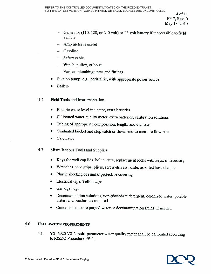
REFER TO THE CONTROLLED DOCUMENT LOCATED ON THE RIZZO EXTRANET FOR THE LATEST VERSION. COPIES PRINTED OR SAVED LOCALLY ARE UNCONTROLLED.

REFER TO THE CONTROLLED DOCUMENT LOCATED ON THE RIZZO EXTRANET FOR THE LATEST VERSION. COPIES PRINTED OR SAVED LOCALLY ARE UNCONTROLLED.

REFER TO THE CONTROLLED DOCUMENT LOCATED ON THE RIZZO EXTRANET FOR THE LATEST VERSION. COPIES PRINTED OR SAVED LOCALLY ARE UNCONTROLLED.

REFER TO THE CONTROLLED DOCUMENT LOCATED ON THE RIZZO EXTRANET FOR THE LATEST VERSION. COPIES PRINTED OR SAVED LOCALLY ARE UNCONTROLLED.

REFER TO THE CONTROLLED DOCUMENT LOCATED ON THE RIZZO EXTRANET FOR THE LATEST VERSION. COPIES PRINTED OR SAVED LOCALLY ARE UNCONTROLLED.

REFER TO THE CONTROLLED DOCUMENT LOCATED ON THE RIZZO EXTRANET FOR THE LATEST VERSION. COPIES PRINTED OR SAVED LOCALLY ARE UNCONTROLLED.

REFER TO THE CONTROLLED DOCUMENT LOCATED ON THE RIZZO EXTRANET FOR THE LATEST VERSION. COPIES PRINTED OR SAVED LOCALLY ARE UNCONTROLLED.

REFER TO THE CONTROLLED DOCUMENT LOCATED ON THE RIZZO EXTRANET FOR THE LATEST VERSION. COPIES PRINTED OR SAVED LOCALLY ARE UNCONTROLLED.

REFER TO THE CONTROLLED DOCUMENT LOCATED ON THE RIZZO EXTRANET FOR THE LATEST VERSION. COPIES PRINTED OR SAVED LOCALLY ARE UNCONTROLLED.

REFER TO THE CONTROLLED DOCUMENT LOCATED ON THE RIZZO EXTRANET FOR THE LATEST VERSION. COPIES PRINTED OR SAVED LOCALLY ARE UNCONTROLLED.

Page 2 of 2
M:\forever\Field Procedures\FP-7 Groundwater Purging Rev. 0 (5/18/10)
WELL PURGING/QUALITY MONITORING FORM (CONTINUED)
Well ID ______________ Date ______________
READING
TIME
TEMP. SPECIFIC
COND. TDS SALINITY PH ORP TURBIDITY DO
( )1 ( )1 ( )1 ( )1 ( )1 ( )1 ( )1 ( )1
1 Specify units of measure. Is Sampling being performed? Yes_________ No_________
Remarks:
Signature(s) Date
REFER TO THE CONTROLLED DOCUMENT LOCATED ON THE RIZZO EXTRANET FOR THE LATEST VERSION. COPIES PRINTED OR SAVED LOCALLY ARE UNCONTROLLED.

REFER TO THE CONTROLLED DOCUMENT LOCATED ON THE RIZZO EXTRANET FOR THE LATEST VERSION. COPIES PRINTED OR SAVED LOCALLY ARE UNCONTROLLED.

REFER TO THE CONTROLLED DOCUMENT LOCATED ON THE RIZZO EXTRANET FOR THE LATEST VERSION. COPIES PRINTED OR SAVED LOCALLY ARE UNCONTROLLED.

Page 1 of 8 FP-8, Rev. 1
May 25, 2011
PROCEDURE FOR GROUNDWATER LEVEL MEASUREMENTS
PAUL C. RIZZO ASSOCIATES, INC.
FP-8, REVISION 1 MAY 25, 2011
1.0 OBJECTIVE AND SCOPE
This Procedure outlines the method to determine the groundwater level from a fixed reference point in a monitoring well or borehole, using either a pressure transducer or an electric water level indicator. This Procedure is meant to provide a general framework for groundwater level measurements; however, site-specific conditions may warrant modifications of the methodology.
2.0 REFERENCES
2.1 RIZZO, FP-2, “Procedure for Field Calibration of Pressure Transducers.”
2.2 RIZZO, QP-2, “Work Plan Preparation.”
2.3 RIZZO, QP-3, “Personnel Qualifications.”
2.4 RIZZO, QP-25, “Records Control.”
2.5 PCR Holdings, Inc., Health and Safety Manual.
2.6 Form FP-8-1, “Groundwater Level Measurement Sheet.”
3.0 TERMS AND DEFINITIONS
3.1 Electric water level indicator (EWLI) – A device used to detect the water surface
in a well. These commonly used devices consist of a spool of small-diameter cable with a weighted probe attached to the end. The probe is lowered into the well and, upon contact with the water, an electrical circuit is closed and a meter, light, and/or buzzer attached to the spool will signal the contact. The electric water level indicator is the preferred instrument for measuring discrete groundwater levels that are below the reference point.
3.2 Flame ionization detector (FID) – Instrumentation used to detect the presence of
volatile organic compounds (VOCs), including methane.
REFER TO THE CONTROLLED DOCUMENT LOCATED ON THE RIZZO EXTRANET FOR THE LATEST VERSION. COPIES PRINTED OR SAVED LOCALLY ARE UNCONTROLLED.

Page 2 of 8 FP-8, Rev. 1
May 25, 2011
3.3 Lower explosion limit (LEL)/Oxygen (O2) detector – Instrumentation used to detect levels of explosive gases and oxygen in the atmosphere.
3.4 Photoionization detector (PID) – Instrumentation used to detect the presence of
VOCs, excluding methane.
3.5 Pressure transducer – A device used to obtain successive water level measurements at specified time intervals within a well. A transducer is positioned at a set depth in a well and measures the pressure of the overlying column of water. A transducer is typically wired to a recorder at the surface to record and log changes in water pressure over time (days to months). The water pressure data are converted to total hydraulic heads based on specified inputs (i.e., density of water, depth at which the transducer has been placed relative to reference point).
3.6 psia – Pounds per square inch (absolute), a unit of pressure that is absolute.
3.7 psig – Pounds per square inch (gauge), a unit of pressure that is relative to atmospheric pressure (i.e., psig = psia – atmospheric pressure).
3.8 Reference point – The point from which all water level measurements are made at
a single location (typically the top of riser pipe or ground surface).
3.9 Top of riser – Top of the solid pipe of a monitoring well that extends up to the ground surface or above ground surface; typically used as a reference point for groundwater elevation measurements.
3.10 Volatile organic compounds (VOCs) – VOCs are organic compounds that are
volatile enough to vaporize and enter the atmosphere under normal atmospheric conditions. VOCs may be harmful or toxic.
4.0 EQUIPMENT
Water level measurement device (pressure transducer or ELWI)
Ruler/measuring tape
Field forms
Timepiece
Well keys
Site map
REFER TO THE CONTROLLED DOCUMENT LOCATED ON THE RIZZO EXTRANET FOR THE LATEST VERSION. COPIES PRINTED OR SAVED LOCALLY ARE UNCONTROLLED.

Page 3 of 8 FP-8, Rev. 1
May 25, 2011
Decontamination supplies
LEL/O2 Detector (optional)
PID/FID (optional)
5.0 CALIBRATION REQUIREMENTS
Aqua TROLL 200 or Level TROLL 700 Pressure Transducer – Calibrate per the requirements of RIZZO Quality Assurance (QA) Program. See RIZZO Procedure FP-2 for the procedure to perform a field check of calibration.
6.0 PROCEDURE
Before starting the procedure, the field personnel conducting the test should ensure that the equipment is clean and operational. Field personnel should review the Work Plan to determine if any special decontamination of equipment is required. If equipment decontamination is required, then the field personnel should follow what is described in the work plan or referenced procedure. Field personnel should review the site-specific Work Plan and/or Health And Safety Plan (if applicable) to determine if any relevant site-specific health and safety concerns exist and ascertain if specific procedures are to be followed. If no site-specific Work Plan and/or Health and Safety Plan is in effect, work should be performed in accordance with the PCR Holdings, Inc. Health and Safety Manual.
6.1 Pre-field Preparation Procedure
6.1.1 Review background and objectives of groundwater level measurement event.
6.1.2 Review site-specific Work Plan for applicable specifications and
requirements.
6.1.3 Arrange scheduling with field personnel, client, and any appropriate agencies.
6.1.4 Select proper measuring equipment as specified by the project-specific
Work Plan:
EWLI
Pressure transducer
REFER TO THE CONTROLLED DOCUMENT LOCATED ON THE RIZZO EXTRANET FOR THE LATEST VERSION. COPIES PRINTED OR SAVED LOCALLY ARE UNCONTROLLED.

Page 4 of 8 FP-8, Rev. 1
May 25, 2011
6.1.5 Calibrate equipment, as needed, as described in Section 5.0. 6.2 Field Preparation Procedure
6.2.1 Use appropriate personnel safety apparel/equipment.
6.2.2 If present, remove monitoring well cap.
6.2.3 If specified in the site-specific Work Plan or Health and Safety Plan, measure the monitoring well head space with a LEL/O2 meter, PID, and/or FID.
6.2.4 Allow three to five minutes to permit groundwater levels to reach equilibrium.
6.2.5 Record the following information Form FP-8-1:
Project name and number
Project location
Weather conditions
Indicate whether the groundwater has a tidal influence
Personnel name(s)
Type of measuring equipment
Serial number of measuring device
Units that water depths and elevations are to be measured
Well ID
Date
Identify the fixed reference point and record the location with the elevation (if known) on the Groundwater Level Measurement Sheet.
6.3 Measurement of point groundwater levels with an EWLI in non-flowing wells (i.e., water level is below reference point).
6.3.1 Lower the EWLI probe into a vessel of water and observe the moment of surface contact to ensure proper functionality of the measuring device.
6.3.2 Allow the EWLI to dry.
REFER TO THE CONTROLLED DOCUMENT LOCATED ON THE RIZZO EXTRANET FOR THE LATEST VERSION. COPIES PRINTED OR SAVED LOCALLY ARE UNCONTROLLED.

Page 5 of 8 FP-8, Rev. 1
May 25, 2011
6.3.3 Slowly lower the EWLI into the borehole or monitoring well until the device indicates contact with the groundwater surface.
6.3.4 If the EWLI is attached to a graduated cable, record the depth measurement at the reference point. If the EWLI is not attached to a graduated cable or if the markings are illegible, mark the cable at the exact position of the reference point. Remove the cable and EWLI from the borehole or monitoring well, and measure the distance between the tip of the EWLI and the marked section of the cable.
6.3.5 Repeat the above steps to ensure precision of the measurement. The measurement should have an accuracy of 0.02 feet (ft) (0.005 meters [m]).
6.3.6 Record measurement on Form FP-8-1.
6.3.7 Record the time on Form FP-8-1.
6.4 Continuous measurement of water level using a pressure transducer in a non-flowing well (i.e., water level is below reference point).
6.4.1 Check that the pressure transducer has been calibrated in accordance with RIZZO QA Program requirements and has a field calibration check performed according to RIZZO Procedure FP-2.
6.4.2 Determine the static water level (depth to water below reference point) and program into data recorder. Record measurement on Form FP-8-1.
6.4.3 Program the desired time interval between measurements and the density of the groundwater (fresh, brackish, or saline) into the recorder.
6.4.4 Determine the depth to the bottom of the well/borehole if it is not already known.
6.4.5 Slowly lower the transducer into the well. The transducer should be positioned in the water column within a depth range specified by the manufacturer and at least 3 ft above the bottom of the borehole.
6.4.6 Periodically throughout the monitoring period, manually measure the groundwater level with a EWLI, as described in Section 6.3. Record measurements along with the time and date each were taken on Form FP-8-1.
6.4.7 Once the monitoring period has ended, slowly remove the transducers from the well/borehole, and use the acquired data and field measurements to obtain groundwater level over time.
REFER TO THE CONTROLLED DOCUMENT LOCATED ON THE RIZZO EXTRANET FOR THE LATEST VERSION. COPIES PRINTED OR SAVED LOCALLY ARE UNCONTROLLED.

Page 6 of 8 FP-8, Rev. 1
May 25, 2011
6.5 Instantaneous measurement of groundwater level using clear tubing attached to a flowing well (i.e., water level is above reference point).
6.5.1 Securely fasten a section of transparent tubing or pipe to a valve on the top
of the artesian well.
6.5.2 Extend the tubing vertically above the cap.
6.5.3 Open the valve and allow groundwater to rise in the tubing.
6.5.4 Measure the stabilized height of the water column in the tubing (i.e., height above the reference point) with a ruler/measuring tape.
6.5.5 Close the valve and remove the tubing from the artesian well.
6.5.6 Record the measurement as water column height above reference point on Form FP-8-1.
6.5.7 Record the time on Form FP-8-1.
6.6 Instantaneous or continuous measurement of groundwater level using a pressure transducer attached to a flowing well (i.e., water level is above reference point).
6.6.1 Use a transducer having a psig range of 0 to 15 psig or less.
6.6.2 Calibrate pressure transducer according to RIZZO Procedure FP-2.
6.6.3 Program water density into the transducer (fresh, brackish, or saline).
6.6.4 Fasten the transducer to the valve port on top of the flowing well.
6.6.5 Measure the distance between the transducer and the reference point and record on Form FP-8-1.
6.6.6 Open the valve and allow the reading to stabilize.
6.6.7 Record the pressure on Form FP-8-1.
6.6.8 Record the time on Form FP-8-1.
6.7 Form FP-8-1 Signatures
6.7.1 Upon completion of Form FP-8-1, the field personnel must sign and date the sheet on the designated line.
REFER TO THE CONTROLLED DOCUMENT LOCATED ON THE RIZZO EXTRANET FOR THE LATEST VERSION. COPIES PRINTED OR SAVED LOCALLY ARE UNCONTROLLED.

Page 7 of 8 FP-8, Rev. 1
May 25, 2011
6.7.2 An approving reviewer (checker) must sign the completed field form
along the designated line. This signature certifies that the documentation on the field form has been reviewed and indicates that the techniques utilized met those outlined in the associated field procedure.
6.8 Potential Problems
6.8.1 Cascading water or condensation within a borehole or a well casing can
cause false readings with EWLIs.
6.8.2 Oil layers may cause problems in determining the true water level in a well. Special devices (oil/water interface probes) are available for measuring the thickness of oil layers and true depth to groundwater, if required.
6.8.3 Monitoring wells that are subject to tidal fluctuations should be read in conjunction with a tidal chart (or, preferably, in conjunction with readings of a tide staff or tide level recorder installed in the adjacent water body).
6.8.4 All water level measurements used to develop a groundwater contour map at a site should be made within the shortest practical time to minimize effects due to weather changes or tidal effects.
7.0 SUITABLE ENVIRONMENTAL CONDITIONS
The Level TROLL 700 or Aqua TROLL 200 pressure transducer is designed to operate within the temperature range of -4° to 176°F (-20 to 80°C).
8.0 PERSONNEL QUALIFICATIONS AND TRAINING REQUIREMENTS
The specific type and location(s) of water level monitoring required for a given project will be specified in a work plan prepared per RIZZO Procedure QP-2. The field personnel responsible for performing the test and the approving reviewer (checker) shall be knowledgeable in the testing/monitoring methodologies used, in accordance with RIZZO Procedure QP-3, and are responsible for obtaining necessary support equipment required to perform the field tests.
9.0 RECORD KEEPING
9.1 Information and data obtained during implementation of this Procedure will be recorded on Form FP-8-1.
REFER TO THE CONTROLLED DOCUMENT LOCATED ON THE RIZZO EXTRANET FOR THE LATEST VERSION. COPIES PRINTED OR SAVED LOCALLY ARE UNCONTROLLED.

Page 8 of 8 FP-8, Rev. 1
May 25, 2011
9.2 Digital photography should be used to document the field activities, when
appropriate. Photos of samples, as well as field activities sites, equipment setup, and conditions encountered during testing should be properly labeled by field personnel and archived according to the site-specific Work Plan.
9.3 Photographs, Field Activity Daily Logs, and completed field forms shall be handled in accordance with RIZZO Procedure QP-25.
REFER TO THE CONTROLLED DOCUMENT LOCATED ON THE RIZZO EXTRANET FOR THE LATEST VERSION. COPIES PRINTED OR SAVED LOCALLY ARE UNCONTROLLED.

Page ____ Of _____
PROJECT NUMBERPERSONNEL
MEASURING DEVICESERIAL #
Yes:_____ No: _____ Maybe: ______ UNITS OF MEASUREMENT
DATE TIME
REFERENCE POINT (e.g., TOC)
WATER LEVEL (DEPTH BELOW REFERENCE POINT)
COMMENTS:
Field Personnel Signature(s) Date
Approving Reviewer Signature Date
FP-8-1, Rev. 1, 5/25/11
NOTES
WELL or PIEZOMETER DESIGNATION
PROJECT NAME/LOCATION
WEATHER CONDITIONS
TIDAL INFLUENCE
GROUNDWATER LEVEL MEASUREMENT SHEET
REFER TO THE CONTROLLED DOCUMENT LOCATED ON THE RIZZO EXTRANET FOR THE LATEST VERSION. COPIES PRINTED OR SAVED LOCALLY ARE UNCONTROLLED.

REFER TO THE CONTROLLED DOCUMENT LOCATED ON THE RIZZO EXTRANET FOR THE LATEST VERSION. COPIES PRINTED OR SAVED LOCALLY ARE UNCONTROLLED.

M:\Forever\Field Procedures\FP-9 Groundwater Monitoring Well Inspection, Rev. 0
CHANGE MANAGEMENT RECORD
Procedure Name: FP-9, Groundwater Monitoring Well Inspection REVISION
NO. DATE
DESCRIPTIONS OF
CHANGES/AFFECTED PAGES PERSON AUTHORIZING
CHANGE1
0 4/20/2010 Original Procedure N/A
NOTE: 1 Person authorizing change shall sign here for the latest revision
REFER TO THE CONTROLLED DOCUMENT LOCATED ON THE RIZZO EXTRANET FOR THE LATEST VERSION. COPIES PRINTED OR SAVED LOCALLY ARE UNCONTROLLED.

1 of 5 FP-9, Rev. 0
April 20, 2010
M:\Forever\Field Procedures\FP-9 Groundwater Monitoring Well Inspection, Rev. 0
PROCEDURE FOR GROUNDWATER MONITORING WELL INSPECTION
PAUL C. RIZZO ASSOCIATES, INC.
FP-9, REVISION 0 APRIL 20, 2010
1.0 OBJECTIVE
A monitoring well that has not been in use or does not have documentation that verifies its well construction and integrity should be inspected prior to its use for data collection. This inspection procedure serves as a guide from the time the inspection begins to the time the well is locked and the inspection ends. Information gathered during the well inspection should be documented on the Well Inspection Form that accompanies this procedure.
2.0 REFERENCES
2.1 RIZZO, QP-2, “Work Plan Preparation.” 2.2 RIZZO, QP-3, “Personnel Qualifications.”
2.3 RIZZO, FP-8, “Procedure for Groundwater Level Measurements.” 2.4 RIZZO, QP-25, “Records Control.” 2.5 RIZZO, Well Inspection Form.
2.5 PRC Holdings, Inc., Health and Safety Manual.
3.0 TERMS AND DEFINITIONS
3.1 Electric Water Level Indicator (EWLI) – A measuring device that allows the measurement of depth-to-water in monitoring wells. The indicator responds when the sensor at the end of the meter touches the water surface and completes an electrical circuit.
3.2 Weighted Tape – A measuring device that is of sufficient length to determine the
monitoring well depth. The tape is marked with depth indicators that allow the measurement of the depth to the bottom of the well.
REFER TO THE CONTROLLED DOCUMENT LOCATED ON THE RIZZO EXTRANET FOR THE LATEST VERSION. COPIES PRINTED OR SAVED LOCALLY ARE UNCONTROLLED.

2 of 5 FP-9, Rev. 0
April 20, 2010
M:\Forever\Field Procedures\FP-9 Groundwater Monitoring Well Inspection, Rev. 0
4.0 EQUIPMENT
The equipment list to perform the inspection should include, but not be limited to, the following:
Electronic Water Level Indicator (EWLI)
Weighted tape of sufficient length to measure the depth of the bottom of the well
Bolt cutters or hack saw in case the lock must be removed
Replacement locks or a nearby location where such locks may be obtained
Camera
Well Inspection Form
5.0 CALIBRATION REQUIREMENTS
The EWLI and the tape used to determine the depth to the bottom of the well should be inspected to verify that they are clean and in good condition. Otherwise, no calibration is required.
6.0 PROCEDURES
Prior to beginning field activities, field personnel should review the site-specific Work Plan and/or Health and Safety Plan (if applicable) to determine if any relevant site-specific health and safety concerns exist or if certain procedures are to be followed. Otherwise, work should be performed in accordance with the PCR Holdings, Inc. Health and Safety Manual. Field personnel should gain permission to access and inspect the well; this includes permission to drive on private roads as needed, access the inside of the well, cut the well lock if necessary, and remove dedicated equipment if necessary. All information pertaining to this well inspection procedure should be recorded on the Well Inspection Form or attached as supplemental pages.
6.1 Existing Monitoring Well Documentation, Well ID, and Well Location
Prior to field inspection of a monitoring well, available well construction or previous well inspection documentation should be collected and reviewed. The documentation should be attached to the Well Inspection Form completed as part of this inspection. This includes documentation of the well location (e.g., figure, map, or survey coordinates) so that the well can be located easily in the future. If the well location is not documented, the field personnel should provide a sketch of the well location that includes major roads, landmarks, and access points. This sketch (ideally on a Field Daily Log form) should be attached to the Well
REFER TO THE CONTROLLED DOCUMENT LOCATED ON THE RIZZO EXTRANET FOR THE LATEST VERSION. COPIES PRINTED OR SAVED LOCALLY ARE UNCONTROLLED.

3 of 5 FP-9, Rev. 0
April 20, 2010
M:\Forever\Field Procedures\FP-9 Groundwater Monitoring Well Inspection, Rev. 0
Inspection Form. Whether or not the documentation is available and attached should be noted on the Well Inspection Form. Upon locating the monitoring well to be inspected, the monitoring well identification marker (Well ID), if visible, should be recorded on the Well Inspection Form. The visibility and condition of the marker should also be noted. If repair or replacement of the marker is required, it should be recorded in the remarks line. If the Well ID is not visible, it should be confirmed by other means, including review of documentation and looking inside the well (Step 6.3). A photograph should be taken (with the permanent Well ID shown, if visible) to provide visual documentation of the well condition at the time of the inspection. Additional photographs that document significant findings of the well condition should be taken as the inspection process proceeds.
6.2 Well Access and Appearance
Field personnel should identify whether the well is accessible and is clear of weeds and debris. The concrete pad should be inspected and its condition should be recorded. The presence of depressions or standing water around the well should be recorded.
6.3 Locking System/Protective Outer Casing
Field personnel should inspect and record the condition of the locking cap. The type, condition, and key availability of the lock should be recorded. If the key works, the well should be unlocked and opened to assess the interior conditions. Care should be used when opening the well to make sure no insects (e.g., wasps) or other animals are present. If the key does not work, permission to cut the lock should be obtained and the lock should be cut and subsequently replaced.
Note any odor coming from the well. If there appears to be an odor that is indicative of volatile organic contamination or any other potentially harmful substance, the field personnel should decide whether the inspection should continue. If the Well ID is visible under the protective casing cap, it should be noted on the Well Inspection Form. If this is the first visible marking of the Well ID, it should be recorded on the Well ID space on the form. The hinge and hasp condition, weep hole condition, and type, inner diameter, and condition of the protective casing should be recorded on the form.
REFER TO THE CONTROLLED DOCUMENT LOCATED ON THE RIZZO EXTRANET FOR THE LATEST VERSION. COPIES PRINTED OR SAVED LOCALLY ARE UNCONTROLLED.

4 of 5 FP-9, Rev. 0
April 20, 2010
M:\Forever\Field Procedures\FP-9 Groundwater Monitoring Well Inspection, Rev. 0
6.4 Well Riser Pipe
The well riser pipe and cap (if any) inside the protective casing should be documented per the Well Inspection Form in the Well Riser Pipe Section, and their condition should be assessed. The vertical reference point to be used for data collection should be found and noted on the form; it is typically located at the top of the innermost casing (riser pipe), and can be recorded as TOC. The total depth of the well should be measured and recorded. The installation depth should be recorded, if known, and compared to the measured depth. The vertical reference point elevation, coordinate system, and reference datum should be recorded, if known. Field personnel should measure and record a depth to water from the vertical reference point, according to RIZZO FP-8, Procedure for Measuring Groundwater Level Measurements.
6.5 Dedicated Monitoring, Purging, and Sampling Equipment
The well being inspected may have a dedicated transducer, pump, or bailer inside the well. If such a device is found in the well, an assessment should be made as to the type, size, and condition of the device. Field personnel should determine whether the equipment should stay in the well or be pulled from the well. If the equipment is to be pulled, permission should be granted by the well owner. All information should be documented on the Well Inspection Form.
6.6 Well Condition Assessment
Based on a careful assessment of all of the previous well inspection sections, field personnel should determine whether the well is useable for collecting data, and if so, which types of data. If repairs are needed prior the well being deemed useable, field personnel should note this. Also, field personnel should provide a list of repairs needed, not just those to make the well viable, but also those to improve the integrity of the well and its potential long-term use. If additional space is required, a Field Activity Daily Log should be completed and attached. Following the well inspection, the well should be locked. Field Personnel should check that the Well Inspection Form is completed and then sign and date the form.
7.0 SUITABLE ENVIRONMENTAL CONDITIONS
Well inspection can be performed under most environmental conditions as long as the safety of field personnel is monitored.
REFER TO THE CONTROLLED DOCUMENT LOCATED ON THE RIZZO EXTRANET FOR THE LATEST VERSION. COPIES PRINTED OR SAVED LOCALLY ARE UNCONTROLLED.

5 of 5 FP-9, Rev. 0
April 20, 2010
M:\Forever\Field Procedures\FP-9 Groundwater Monitoring Well Inspection, Rev. 0
8.0 PERSONNEL QUALIFICATIONS
Field personnel responsible for performing the inspection shall be knowledgeable in the methodologies used, in accordance with RIZZO Procedure QP-3, Personnel Qualifications, and shall be responsible for obtaining the necessary support and/or equipment required to perform the procedure.
9.0 RECORDKEEPING
9.1 Information and data procured will be recorded on the Well Inspection Form.
9.2 Digital photography should be used to document the field activities when
appropriate. Photos of the well casing, the hasp and lock, the well pad, and others, as appropriate, should be taken and properly labeled by field personnel and archived according to the site-specific Work Plan prepared.
9.3 Photographs, Field Activity Daily Logs, and completed field forms shall be handled in accordance with RIZZO Procedure QP-25, Records Control.
REFER TO THE CONTROLLED DOCUMENT LOCATED ON THE RIZZO EXTRANET FOR THE LATEST VERSION. COPIES PRINTED OR SAVED LOCALLY ARE UNCONTROLLED.

Page 1 of 2
M:\Forever\Field Procedures\FP-9 Groundwater Monitoring Well Inspection, Rev. 0 Rev. 0 April 20, 2010
Project Name/Number: Field Personnel: Date:
Existing Monitoring Well Documentation, Well Location, and Well ID:
Well construction or previous well inspection documentation:Available? Yes NoAttached? Yes No
Well location documentation:Available? Yes No If no, provide a sketch and attach.Attached? Yes No
Well ID:Visible? Yes No Well IDGood Condition? Yes NoType of Marker?
Provide details of issues:
Well Access and Appearance:
Well is accessible? Yes No
Vicinity of well is clear of weeds and debris? Yes No
Concrete pad is in good condition? Yes No
Presence of depressions or standing water around well? Yes No
Provide details of issues:
Locking System/Protective Outer Casing:
Locking cap: Good condition? Yes NoLock: Type?
Good condition? Yes NoKey available/works? Yes NoLock cut? Yes No
Noticeable odor from well? Yes NoIf yes, should inspection continue? Yes No Provide details and recommendations.
Well ID is visible inside well? Yes No If necessary, record Well ID above.
Hinge/hasp: Good condition? Yes NoWeep hole: Good condition? Yes No
Protective outer casing: Material type?Inner diameter (units)?Good condition? Yes No
Provide details of issues:
WELL INSPECTION FORM
REFER TO THE CONTROLLED DOCUMENT LOCATED ON THE RIZZO EXTRANET FOR THE LATEST VERSION. COPIES PRINTED OR SAVED LOCALLY ARE UNCONTROLLED.

WELL INSPECTION FORM (CONTINUED) Page 2 of 2
M:\Forever\Field Procedures\FP-9 Groundwater Monitoring Well Inspection, Rev. 0 Rev. 0 April 20, 2010
Well Riser Pipe:
Riser pipe: Material type?Inner diameter (units)?Good condition? Yes No
Riser cap exists? Yes NoIf yes: Good condition? Yes No
Vertical reference point to be used for data collection? (TOC, other)
Measured total depth (units)?
Installation depth, if known (units)?
Reference point elevation, if known (units)?
Coordinate system and reference datum, if known?
Measured depth to water (units)?
Provide details of issues:
Dedicated Monitoring, Purging, or Sampling Equipment:
Equipment present in the well? Yes NoIf yes: Type?
Good condition? Yes NoPulled or left in well?
Provide details of issues:
Well Condition Assessment:
Well is useable to collect data? Yes No
If yes, which types? Water levels? Yes NoWater samples? Yes NoAquifer testing? Yes No
Provide a detailed list of repairs needed to improve the well integrity and its potential long-term use.
Field Engineer/Geologist: Signature Date
REFER TO THE CONTROLLED DOCUMENT LOCATED ON THE RIZZO EXTRANET FOR THE LATEST VERSION. COPIES PRINTED OR SAVED LOCALLY ARE UNCONTROLLED.

REFER TO THE CONTROLLED DOCUMENT LOCATED ON THE RIZZO EXTRANET FOR THE LATEST VERSION. COPIES PRINTED OR SAVED LOCALLY ARE UNCONTROLLED.

M:\Forever\Field Procedures\FP-10 Procedure for Cold Storage Packaging and Transport of Environmental Water and Soil Samples, Rev. 0
CHANGE MANAGEMENT RECORD
Procedure Name: FP-10, Cold Storage Packaging and Transport of Environmental Water and Soil Samples
REVISION NO.
DATE DESCRIPTIONS OF CHANGES/AFFECTED PAGES
PERSON AUTHORIZING CHANGE1
0 4/20/2010 Original Procedure N/A
NOTE: 1 Person authorizing change shall sign here for the latest revision
REFER TO THE CONTROLLED DOCUMENT LOCATED ON THE RIZZO EXTRANET FOR THE LATEST VERSION. COPIES PRINTED OR SAVED LOCALLY ARE UNCONTROLLED.

Page 1 of 5 FP-10, Rev 0 April 20, 2010
M:\Forever\Field Procedures\FP-10 Procedure for Cold Storage Packaging and Transport of Environmental Water and Soil Samples, Rev. 0
COLD-STORAGE PACKAGING AND
TRANSPORT OF ENVIRONMENTAL WATER AND SOIL SAMPLES
PAUL C. RIZZO ASSOCIATES, INC.
FP-10, REVISION 0 APRIL 12, 2010
1.0 OBJECTIVE
This procedure provides a methodology for cold-storage packaging and transport of environmental water and soil samples. An emphasis is placed on retaining the integrity of the sample containers, ensuring the arrival of the samples at the laboratory in sufficient time to meet required analytical holding times, and preserving the samples’ chemical and physical properties. This procedure includes the relevant field activities following the commencement of a sample-specific sampling procedure and ending upon the associated samples’ arrival at the destination laboratory. The proper storage of the samples at the laboratory prior to analysis is not included in this procedure.
2.0 REFERENCES
2.1 RIZZO, QP-26, “Sample Identification and Control”
2.2 RIZZO, QP-25, “Records Control”
2.3 RIZZO, QP-3, “Personnel Qualifications”
2.4 PCR Holdings, Inc., Health and Safety Manual
3.0 TERMS AND DEFINITIONS
3.1 Cold-storage – The storage of samples in an appropriate container (cooler) at 39±3.5°F (4±2°C).
3.2 Courier – A commercial company responsible for the shipment of the samples.
3.3 International Air Transport Association (IATA) – An international industry trade group responsible for defining all airline rules and regulations.
3.4 Sample holding time – The amount of time a sample may be stored after collection and prior to analysis without significantly affecting the analytical results.
REFER TO THE CONTROLLED DOCUMENT LOCATED ON THE RIZZO EXTRANET FOR THE LATEST VERSION. COPIES PRINTED OR SAVED LOCALLY ARE UNCONTROLLED.

Page 2 of 5 FP-10, Rev 0 April 20, 2010
M:\Forever\Field Procedures\FP-10 Procedure for Cold Storage Packaging and Transport of Environmental Water and Soil Samples, Rev. 0
3.5 Temperature blank – A container of water included in a shipping container to be
used to determine the temperature of all samples stored in the container.
3.6 Trip blank – A set of two or three vials of analyte-free water provided by the laboratory, which is included in a shipping container and accompany the sample containers identified for analysis of volatile organic compounds (VOCs) throughout a sampling event. A trip blank is analyzed for VOCs to determine any contamination of the samples stored in the container during the sampling event and container transport.
4.0 EQUIPMENT AND SUPPLIES
• Chain of Custody Records
• Bubble wrap
• Coolers
• Trip blanks (if specified in the work plan)
• Temperature blanks (if specified in the work plan)
• Zipper-type plastic bags
• Miscellaneous packing materials
• Ice and/or ice packs
• Paper towels
• Waterproof tape
• Packaging tape
• Custody seals, if required 5.0 CALIBRATION REQUIREMENTS
Not applicable.
REFER TO THE CONTROLLED DOCUMENT LOCATED ON THE RIZZO EXTRANET FOR THE LATEST VERSION. COPIES PRINTED OR SAVED LOCALLY ARE UNCONTROLLED.

Page 3 of 5 FP-10, Rev 0 April 20, 2010
M:\Forever\Field Procedures\FP-10 Procedure for Cold Storage Packaging and Transport of Environmental Water and Soil Samples, Rev. 0
6.0 PROCEDURE Field personnel should review the site-specific work plan and/or health and safety plan (if applicable) to determine if any relevant site-specific health and safety concerns exist and to ascertain which procedures are to be followed. If no site-specific work plan and/or health and safety plan is in effect, work should be performed in accordance with the PCR Holdings, Inc., Health and Safety Manual. 6.1 Individual Sample Preparation
6.1.1 Wipe soil or excess water from the exterior of the sample container.
6.1.2 Glass containers (including trip blanks, if applicable) should be wrapped in bubble wrap and sealed in a zipper-type plastic bag.
6.1.3 Plastic containers should be sealed in a zipper-type plastic bag. Protective wrapping is not required.
6.1.4 Temperature blanks do not require protective wrapping.
6.2 Sample Organization
6.2.1 Samples and associated trip blanks (if applicable) should be sorted according to lab destination and/or sample type.
6.2.2 A temperature blank may be included in each shipping container, as
specified by the laboratory and/or site-specific work plan.
6.3 Chain of Custody
6.3.1 Chain of Custody Records must be completed following RIZZO Procedure QP-26.
6.3.2 Sample identification labels should be checked against the Chain of
Custody Record before shipment to ensure that each sample is in the correct shipping container.
6.3.3 The Chain of Custody Record will be copied and the original will be sealed in a plastic bag with a business card of the sender, placed in a gallon-size zipper-type plastic bag, and taped to the inside lid of each shipping container.
REFER TO THE CONTROLLED DOCUMENT LOCATED ON THE RIZZO EXTRANET FOR THE LATEST VERSION. COPIES PRINTED OR SAVED LOCALLY ARE UNCONTROLLED.

Page 4 of 5 FP-10, Rev 0 April 20, 2010
M:\Forever\Field Procedures\FP-10 Procedure for Cold Storage Packaging and Transport of Environmental Water and Soil Samples, Rev. 0
6.4 Packaging of Samples in Coolers
6.4.1 If the cooler has any drains, the drains must be sealed with waterproof tape on both the inside and outside of the cooler to prevent leakage.
6.4.2 Coolers should be lined with a plastic covering (garbage bag) and/or protective material (bubble wrap, foam sheeting, etc.).
6.4.3 All samples and associated blanks will be stored between top and bottom layers of ice and/or ice packs. The ice will be double-bagged in zipper-type plastic bags.
6.4.4 Packaging material (bubble wrap, crumpled paper, etc.) should be used to fill voids.
6.4.5 Coolers should be closed and sealed with packing tape. If required by the site-specific work plan, two custody seals (standard RIZZO seal or laboratory-specific seal) should be placed across the opening of the cooler.
6.5 Sample Transportation – Domestic
6.5.1 All samples should be shipped to ensure that they arrive at the laboratory
within their sample-specific holding times, as specified in the applicable Work Plan and/or following laboratory guidelines. When possible, delivery by a RIZZO employee or overnight commercial delivery with a reputable courier service is preferred.
6.5.2 Samples must be shipped in compliance with all applicable domestic regulations. The courier should be consulted regarding such regulations.
6.5.3 A designated RIZZO personnel member should confirm the laboratory’s receipt of the samples after the specified delivery time.
6.6 Sample Transportation – International
6.6.1 All samples should be shipped to ensure that they arrive at the laboratory within their sample-specific holding times, as specified in the applicable work plan and/or following laboratory guidelines.
6.6.2 Samples must be shipped in compliance with all applicable international regulations. The international transport of certain sample types and/or chemical preservatives may be prohibited. The courier or IATA should be consulted regarding specific regulations.
REFER TO THE CONTROLLED DOCUMENT LOCATED ON THE RIZZO EXTRANET FOR THE LATEST VERSION. COPIES PRINTED OR SAVED LOCALLY ARE UNCONTROLLED.

Page 5 of 5 FP-10, Rev 0 April 20, 2010
M:\Forever\Field Procedures\FP-10 Procedure for Cold Storage Packaging and Transport of Environmental Water and Soil Samples, Rev. 0
6.6.3 A designated RIZZO personnel member should confirm the laboratory’s receipt of the samples after the specified delivery time.
7.0 SUITABLE ENVIRONMENTAL CONDITIONS
Samples requiring cold storage must be transported and stored at 39±3.5°F (4±2°C). During inclement weather and/or extreme temperature conditions, care must be taken to store all samples within a climate-controlled setting immediately upon retrieval. The samples must not be allowed to freeze.
8.0 PERSONNEL QUALIFICATIONS AND TRAINING REQUIREMENTS
The specific types of samples to be packaged and shipped, including their holding times, will be specified in the site-specific work plan. The field personnel responsible for packaging and shipping samples shall be knowledgeable in the methodologies used, in accordance with RIZZO QP-3, and are responsible for obtaining the necessary support and/or equipment required to perform the procedure.
9.0 PROVISION FOR DATA ACQUISITION
9.1 Required information will be recorded on a Chain of Custody Record.
9.2 Digital photography should be used to document the field activities when appropriate. Photos of samples, as well as field activities, sites, equipment set-up, and conditions encountered during testing should be properly labeled by field personnel and archived according to the site-specific work plan.
9.3 Records associated with this procedure shall be stored per the requirements specified in RIZZO QP-25.
REFER TO THE CONTROLLED DOCUMENT LOCATED ON THE RIZZO EXTRANET FOR THE LATEST VERSION. COPIES PRINTED OR SAVED LOCALLY ARE UNCONTROLLED.

REFER TO THE CONTROLLED DOCUMENT LOCATED ON THE RIZZO EXTRANET FOR THE LATEST VERSION. COPIES PRINTED OR SAVED LOCALLY ARE UNCONTROLLED.

REFER TO THE CONTROLLED DOCUMENT LOCATED ON THE RIZZO EXTRANET FOR THE LATEST VERSION. COPIES PRINTED OR SAVED LOCALLY ARE UNCONTROLLED.

Page 1 of 10 FP-11, Rev. 1 May 25, 2011
PUMPING TEST PROCEDURE
FP-11, REVISION 1
MAY 25, 2011 1.0 OBJECTIVE AND SCOPE
1.1 Objective
This Procedure describes a method for performing pumping tests to determine the hydraulic properties of water-bearing formations and to evaluate to what extent relatively permeable geologic units are hydraulically connected, both vertically and horizontally.
1.2 Scope
A pumping test is a controlled field procedure that is generally carried out by monitoring the water level over time in a pumping well and observation wells (if present), while water from the pumping well is being discharged at a constant or variable rate. Pumping tests provide results that are representative of aquifer characteristics across the testing area. Results from alternative methods may only be representative of a discrete sample or limited area around the test hole or well. A pumping test can also be used to determine the hydraulics of secondary aquifer flow. Pumping tests may not be justified for all types of investigations, as they typically require a greater amount of labor and expense. The aquifer characteristics that can be obtained from pumping tests include hydraulic conductivity (K), transmissivity (T), specific yield (Sy) for unconfined aquifers, storage coefficient (S) for confined aquifers, and the interconnection between water-bearing formations. Also, the influence and location of recharge or impermeable boundaries can be identified. A numerical estimate of aquifer parameters can be determined by graphical solutions and computer programs. A pumping test normally consists of four phases: a preliminary monitoring phase, a step-drawdown phase, a pumping phase resulting in water level drawdown, and a recovery phase after the pump has been turned off. Water level monitoring is conducted during all of these phases.
REFER TO THE CONTROLLED DOCUMENT LOCATED ON THE RIZZO EXTRANET FOR THE LATEST VERSION. COPIES PRINTED OR SAVED LOCALLY ARE UNCONTROLLED.

Page 2 of 10 FP-11, Rev. 1 May 25, 2011
2.0 REFERENCES
2.1 Form FP-11-1, “Pumping Well Data Collection Form.”
2.2 Form FP-11-2, “Observation Well Data Collection Form.”
2.3 Kruseman, G.P. and N.A. de Ridder, 1991, “Analysis and Evaluation of Pumping
Test Data,” Second Edition, International Institute for Land Reclamation and Improvement Publication 47, Wageningen, The Netherlands.
2.4 PCR Holdings, Inc., Health and Safety Manual.
2.5 RIZZO, FP-2, “Calibration of Pressure Transducers.”
2.6 RIZZO, FP-17, “Calibration of Buckets and Drums.”
2.7 RIZZO, QP-3, “Personnel Qualifications.”
2.8 RIZZO, QP-25, “Records Control.”
2.9 Sevee, J., 1991, “Methods and Procedures for Defining Aquifer Parameters,” In D. M. Nielsen (editor), Practical Handbook of Ground-Water Monitoring, Lewis Publishers, Inc., Chelsea, Michigan, pp. 397-448.
2.10 Stallman, R. W., 1983, “Aquifer-Test Design, Observation and Data Analysis,” U.S. Geological Survey Techniques of Water-Resource Investigations, Book 3, Chapter B1, United States Government Printing Office, Washington, D. C.
2.11 Walton, W. C., 1987, “Groundwater Pumping Tests, Design and Analysis,” Lewis Publishers, Inc. Chelsea, Michigan.
3.0 DEFINITIONS
3.1 Cone of influence – The area around a pumping well where the hydraulic head in the aquifer has been lowered by pumping. Also known as cone of depression.
3.2 Confined aquifer – An aquifer that is bounded above and below by an aquitard or aquiclude (strata of lower permeability). The potentiometric surface of a confined aquifer is higher than the base of the upper confining layer.
3.3 Unconfined aquifer – An aquifer that is bounded below by an aquitard or aquiclude but is not necessarily bounded above. The potentiometric surface of an
REFER TO THE CONTROLLED DOCUMENT LOCATED ON THE RIZZO EXTRANET FOR THE LATEST VERSION. COPIES PRINTED OR SAVED LOCALLY ARE UNCONTROLLED.

Page 3 of 10 FP-11, Rev. 1 May 25, 2011
unconfined aquifer lies at or below the top of the aquifer and is at equilibrium with the atmosphere; therefore, the aquifer might be only partially saturated. Also referred to as a water-table aquifer.
3.4 Discharge – Volume of water removed per unit time.
3.5 Drawdown(s) – Difference between the initial static water level and the water level at a given time during the pumping or recovery phases of the pumping test (dynamic water level).
3.6 Hydraulic conductivity (K) – The flow rate per unit cross-sectional area of porous medium under the influence of a unit hydraulic gradient. It is a function of both the media and of the fluid flowing through it. Units of measure most commonly used are centimeter per second (cm/s), feet per day (ft/day), meters per day (m/day), and gallons per day per square foot (gpd/ft2).
3.7 Specific capacity – Rate of well yield per unit drawdown. It is often expressed as gallons per minute per foot of drawdown (e.g., gpm/ft).
3.8 Specific storage (Ss) – The volume of water released from or taken into storage per unit volume of aquifer per unit change in head (e.g., 1/ft).
3.9 Specific yields (Sy) – The volume of water that an unconfined aquifer releases from storage per unit surface area of aquifer per unit decline of the water table.
3.10 Storage coefficient (S) – The volume of water a confined aquifer releases from or takes into storage per unit volume of aquifer per unit change in head. The product of specific storage times saturated thickness. Also known as storativity.
3.11 Transmissivity (T) – The flow rate per unit width of saturated aquifer under a unit hydraulic gradient. Also, equal to hydraulic conductivity times thickness of the saturated aquifer. Units of measure most commonly used are feet squared per day (ft2/day), meters squared per day (m2/day), centimeters squared per second (cm2/sec), and gallons per day per foot (gpd/ft).
4.0 EQUIPMENT
A checklist of suggested equipment and supplies needed to implement this procedure is provided below.
Pressure transducer(s)
Electronic data logger
Electric water level indicator
REFER TO THE CONTROLLED DOCUMENT LOCATED ON THE RIZZO EXTRANET FOR THE LATEST VERSION. COPIES PRINTED OR SAVED LOCALLY ARE UNCONTROLLED.

Page 4 of 10 FP-11, Rev. 1 May 25, 2011
Submersible pump
Generator
Pump control box
Flow measuring device (e.g., flow meter or bucket of known volume with stopwatch)
Support equipment (e.g., winch)
Manufacturer’s operating manuals for equipment selected above
Weighted tape measure
Tape measure (graduated in tenths or hundredths of a foot or meter)
Calculator
Miscellaneous plumbing supplies, tools, duct tape, etc.
Any additional supplies listed in associated procedures, as needed.
5.0 CALIBRATION REQUIREMENTS
5.1 Pressure transducers shall be calibrated according to RIZZO Procedure FP-2,
“Calibration of Pressure Transducers.”
5.2 Buckets and drums used for measuring volume shall be calibrated according to RIZZO Procedure FP-17, “Calibration of Buckets and Drums.”
5.3 Other measurement and test equipment (e.g., flow meter and stopwatch) shall be calibrated according to the RIZZO Quality Assurance (QA) Program.
6.0 PROCEDURE
6.1 Preparation
6.1 1 Prior to beginning field activities, field personnel shall review the site-specific Work Plan to determine the project-specific requirements. Specific equipment to be used should be identified and checked to make sure it is clean (and decontaminated, if necessary), operational, and calibrated according to the RIZZO QA Program.
6.1.2 Field personnel shall review the site-specific Work Plan and/or Health and
Safety Plan (if applicable) to determine if any relevant site-specific health and safety concerns exist, including the need to monitor volatile organic gas around the well head. If no site-specific Work Plan and/or Health and
REFER TO THE CONTROLLED DOCUMENT LOCATED ON THE RIZZO EXTRANET FOR THE LATEST VERSION. COPIES PRINTED OR SAVED LOCALLY ARE UNCONTROLLED.

Page 5 of 10 FP-11, Rev. 1 May 25, 2011
Safety Plan is in effect, work should be performed in accordance with the PCR Holdings, Inc. Health and Safety Manual.
6.1.3 Field personnel shall obtain, if available, well installation information for
each monitoring well, including well location, well ID, well installation depth, well diameter, and screened interval depths. Field personnel should verify that each well is useable by reviewing well inspection, well development, and/or purging/monitoring records. Field personnel will secure permission and be able to access all monitoring wells to be monitored. This includes permission to open the wells and cut/replace the locks, if necessary.
6.1.4 Field personnel shall ensure that permission to discharge the groundwater
is obtained (an agency permit may be required) or that a containment system is available if the groundwater is contaminated. If groundwater is to be discharged directly to the ground, the discharge line should be sufficiently long so that water does not infiltrate the testing area (e.g., at least 100 feet (ft) from the pumping and observation wells). The discharge water may be routed to a storm sewer or surface water body if uncontaminated and approved. Otherwise, it may be necessary to temporarily store the discharge water in tanks, drums, or in a lined pit if collection is required. If contaminated water is pumped during the test, the water may need to be stored, treated, or disposed of in an appropriate manner, with client/regulatory approval.
6.1.5 The two field forms (Form FP-11-1 and Form FP-11-2) provided to record
information for the pumping well and observation wells are intended to be utilized for all four possible phases of testing: preliminary monitoring, step-drawdown test phase, pumping phase, and recovery phase. Once the initial information is completed for each well, the forms can be utilized to record information as the work progresses. Complete the initial information on Form FP-11-1 and Form FP-11-2, including the Project name, Project number, well ID(s), reference point description, and reference point elevation (if known). Record the equipment information pertaining to flow measurement and water level monitoring in the table provided.
6.2 Pressure Transducer Installation
6.2.1 Pressure transducers may be utilized during some or all phases of testing.
This installation text is applicable for all subsequent sections where a transducer is utilized.
6.2.2 Install the transducer and cable in the well (pumping and/or observation
well) below the estimated target drawdown depth. Be sure the depth of
REFER TO THE CONTROLLED DOCUMENT LOCATED ON THE RIZZO EXTRANET FOR THE LATEST VERSION. COPIES PRINTED OR SAVED LOCALLY ARE UNCONTROLLED.

Page 6 of 10 FP-11, Rev. 1 May 25, 2011
submergence is within the design range and will not exceed that stamped on the transducers. Secure or tape the transducer cable to the top of the well to maintain the transducer at a constant depth.
6.2.3 Connect the transducer cable to the electronic data logger and enter the
initial water level (static water level), Project name, location, well ID, and density of water (i.e., fresh, brackish, or saline) into the electronic data logger in accordance with the manufacturer’s operating instructions.
6.2.4 Connect the pressure transducers to data logger (rugged reader or laptop
computer) to monitor drawdown changes in real time (as a check for proper functioning of the pressure transducers).
6.2.5 Program the pressure transducers to record the water level at 30-second
intervals for pumping wells and one-minute (60-second) intervals for observation wells.
6.3 Preliminary Monitoring
6.3.1 Monitor water levels at the site by recording manual measurements and/or
using a pressure transducer with continuous data logger. In the table provided, record the date, time, and testing phase as “preliminary.”
6.3.2 Record manual measurements. If using a continuous data logger, make a note in the Comments column. As a general rule, the period of observation should be at least twice the length of estimated time of pumping (Stallman, 1983). The records help determine if the aquifer is experiencing an increase or decrease in head over time that may be caused by a recent recharge event, tidal fluctuation, pumping in the area, or variations in barometric pressure.
6.4 Step-Drawdown Test
6.4.1 A step-drawdown test typically is performed to determine an optimum
pumping rate for the subsequent pumping test, and to check the proper functioning of the pumping equipment.
6.4.2 Install a submersible or turbine pump in the pumping well. If a flow meter
is used, it should be installed in the discharge line to monitor the volume discharged during the test. A gate valve on the discharge pipe can be used to control the pumping rate. Record the date, time, and testing phase as “step-drawdown test.” Measure and record an initial depth to water. If an in-line flow meter is used, read and record the initial volume reading prior to turning on the pump.
REFER TO THE CONTROLLED DOCUMENT LOCATED ON THE RIZZO EXTRANET FOR THE LATEST VERSION. COPIES PRINTED OR SAVED LOCALLY ARE UNCONTROLLED.

Page 7 of 10 FP-11, Rev. 1 May 25, 2011
6.4.3 Install the pressure transducer in the pumping well as described in Section 6.2.
6.4.4 Begin pumping at a low, constant rate until the drawdown within the well
stabilizes. If using a flow meter, record volume readings and estimate/record the flow rate. If using a bucket and stopwatch, record an estimated flow rate.
6.4.5 Increase the rate to a higher constant discharge until the water level
stabilizes once more. Estimate/record the flow rate with either the flow meter or bucket/stopwatch. Continue to increase the pumping rate in a step-wise manner such that for each step the drawdown stabilizes. A minimum of three successively greater rates should be tried, but if a higher flow rate produces continuing drawdown (i.e., the well will go dry) then the flow rate should be decreased. Generally, the duration of each step should be between one-half and two hours.
6.4.6 When testing has been completed, shut off the pump. If using a flow
meter, record the final volume reading. Record the final, optimum flow rate. Ensure that the gate valve on the discharge pipe is left at the optimum setting before pumping is terminated so that the pump will operate at the optimum pumping rate during the actual test.
6.5 Pumping and Recovery Phases
6.5.1 Manually measure static water levels in the pumping well and any
observation well(s) using a water level meter after all equipment has been deployed. Record these measurements along with the date, time, and testing phase as “pumping phase.”
6.5.2 If an in-line flow meter is used, read and record the initial volume reading prior to turning on the pump.
6.5.3 Initiate pumping at the specified discharge rate (optimum rate obtained through step-drawdown test). If using a flow meter, record volume readings and estimate/record the flow rate periodically during the pumping phase of the test. If using a bucket and stopwatch, record estimated flow rates periodically during the pumping phase of the test.
6.5.5 When the pumping phase has been completed, shut off the pump and
record the. If using a flow meter, record the final volume reading and final estimated flow rate.
6.5.6 Continue water level monitoring while water levels recover in the
pumping and observation wells. Record manual measurements along with
REFER TO THE CONTROLLED DOCUMENT LOCATED ON THE RIZZO EXTRANET FOR THE LATEST VERSION. COPIES PRINTED OR SAVED LOCALLY ARE UNCONTROLLED.

Page 8 of 10 FP-11, Rev. 1 May 25, 2011
the date, time, and testing phase as “recovery phase” periodically during the recovery phase of the test.
6.5.7 Continue monitoring until the water level has stabilized at a level that approaches the pre-test static values (e.g., 80 percent recovery).
6.5.8 If manual measurements are to be collected, either because pressure transducers malfunction or are not available, a suggested schedule for measurement in pumping and observation wells is as follows:
TABLE 1
SUGGESTED MINIMUM FREQUENCY OF WATER LEVEL MEASUREMENTS IN THE PUMPED WELL
(KRUSEMAN AND DE RIDDER, 1991)
ELAPSED TIME SINCE START OR STOP OF TEST
INTERVAL BETWEEN MEASUREMENTS
0 to 5 minutes 0.5 minutes 5 to 60 minutes 5 minutes
60 to 120 minutes 20 minutes 120 minutes to termination 60 minutes
TABLE 2
SUGGESTED MINIMUM FREQUENCY OF WATER LEVEL MEASUREMENTS IN AN OBSERVATION WELL
(KRUSEMAN AND DE RIDDER, 1991)
TIME ELAPSED SINCE START OR STOP OF TEST
INTERVAL BETWEEN MEASUREMENTS
0 to 2 minutes 10 seconds 2 to 5 minutes 30 seconds 5 to 15 minutes 1 minute 15 to 50 minutes 5 minutes 50 to 100 minutes 10 minutes 100 to 300 minutes 30 minutes
5 to 48 hours 60 minutes 48 hours to termination 3 times a day
REFER TO THE CONTROLLED DOCUMENT LOCATED ON THE RIZZO EXTRANET FOR THE LATEST VERSION. COPIES PRINTED OR SAVED LOCALLY ARE UNCONTROLLED.

Page 9 of 10 FP-11, Rev. 1 May 25, 2011
6.6 Post-Test Activities
6.6.1 Download data from the pressure transducers:
Stop the data logging sequence.
Store all data internally or on compact disc for transfer to main computer for analysis.
Disconnect data logger battery at the end of the day’s activities.
6.6.2 Remove pressure transducers and cables from all wells, decontaminate or
clean as appropriate, and properly store equipment.
6.6.3 Remove equipment from the pumping well and clean pump, hoses, and cable.
6.6.4 All personnel performing the pumping test should sign and date the
forms.
6.6.5 An approving reviewer (checker) must sign the completed field form along the designated line. This signature certifies that the documentation on the field form has been reviewed and indicates that the techniques utilized met those outlined in this field procedure.
7.0 SUITABLE ENVIRONMENTAL CONDITIONS
The design of a pumping test is not only dependent on the purpose of the test but also on the hydrogeologic environment. A pumping well should be located far enough away from hydraulic boundaries to permit recognition of drawdown trends before boundary conditions influence the drawdown data (Sevee, 1991). In addition, to minimize the effect of stream, river, or lake bed infiltration, the pumping well should be located at a distance equal to or exceeding the aquifer thickness from the possible boundary (Walton, 1987). However, if the intent is to induce recharge, then the pumping well should be located as close to the boundary as possible (Sevee, 1991). In places that experience severe winter climate where the frostline may extend to depths of several feet, pumping tests should be avoided in areas where the water table is near the ground surface. Under these circumstances, the frozen soil may act as a confining bed, combined with delayed yield characteristics, and make the results of the test unreliable. Significant changes in hydrologic conditions, such as a heavy rain or a sudden fall or rise of a nearby river during the test, could make the resulting pumping/recovery data difficult to correct and/or interpret. In such cases, the test may need to be postponed or repeated
REFER TO THE CONTROLLED DOCUMENT LOCATED ON THE RIZZO EXTRANET FOR THE LATEST VERSION. COPIES PRINTED OR SAVED LOCALLY ARE UNCONTROLLED.

Page 10 of 10 FP-11, Rev. 1 May 25, 2011
when the conditions return to normal (Kruseman and de Ridder, 1991). Temperatures should fall within the operational range of equipment to be used.
8.0 PERSONNEL QUALIFICATIONS AND TRAINING REQUIREMENTS
The field personnel performing pumping tests and the approving reviewer (checker) shall be knowledgeable in the methodologies used and shall be qualified in accordance with RIZZO Procedure QP-3. Field personnel are responsible for obtaining the necessary support and/or equipment required to perform the procedure.
9.0 RECORD KEEPING
9.1 Information and data collected during pumping tests will be recorded on Form FP-11-1 and Form FP-11-2.
9.2 Digital photography should be used to document the field activities when
appropriate. Completed field forms should be collected at the end of each day and properly stored according to requirements specified in RIZZO Procedure QP-25.
REFER TO THE CONTROLLED DOCUMENT LOCATED ON THE RIZZO EXTRANET FOR THE LATEST VERSION. COPIES PRINTED OR SAVED LOCALLY ARE UNCONTROLLED.

Page _____ of ______
FP-11-2, Rev 1, 5/25/11
PUMPING WELL DATA COLLECTION FORM
Project Name Pumping Well ID
Project Number Pump Depth (units)
Ref. Point Description Ref. Pt. Elevation, if known (units)
MEASUREMENT AND TEST EQUIPMENT SERIAL NUMBER DATE OF
CALIBRATION CALIBRATION DUE DATE
DATE TIME TESTING
PHASE
FLOW METER
READING (IF
USED) ( )1
ESTIMATED
FLOW RATE ( )1
DEPTH TO
WATER ( )1
COMMENTS
1 Specify units of measure.
Field Personnel Signature(s) Date
Approving Reviewer (checker) Signature Date
REFER TO THE CONTROLLED DOCUMENT LOCATED ON THE RIZZO EXTRANET FOR THE LATEST VERSION. COPIES PRINTED OR SAVED LOCALLY ARE UNCONTROLLED.

Page _____ of ______ PUMPING WELL DATA COLLECTION FORM
(Continued) Pumping Well ID
Observation Well ID________________
FP-11-1, Rev 1, 5/25/11
DATE TIME TESTING
PHASE
FLOW METER
READING (IF
USED) ( )1
ESTIMATED
FLOW RATE ( )1
DEPTH TO
WATER ( )1
COMMENTS
1 Specify units of measure.
Field Personnel Signature(s) Date
Approving Reviewer (checker) Signature Date
REFER TO THE CONTROLLED DOCUMENT LOCATED ON THE RIZZO EXTRANET FOR THE LATEST VERSION. COPIES PRINTED OR SAVED LOCALLY ARE UNCONTROLLED.

Page _____ of _____
FP-11-2, Rev 1, 5/25/11
OBSERVATION WELL DATA COLLECTION FORM
Project Name Pumping Well ID
Project Number Observation Well ID
Reference Point Description Ref. Point Elevation, if known (units)
MEASUREMENT AND TEST EQUIPMENT SERIAL NUMBER DATE OF
CALIBRATION CALIBRATION DUE DATE
DATE TIME TESTING PHASE DEPTH TO
WATER ( ) 1
COMMENTS
1 Specify units of measure.
Field Personnel Signature(s) Date
Approving Reviewer (checker) Signature Date
REFER TO THE CONTROLLED DOCUMENT LOCATED ON THE RIZZO EXTRANET FOR THE LATEST VERSION. COPIES PRINTED OR SAVED LOCALLY ARE UNCONTROLLED.

Page _____ of ______
OBSERVATION WELL DATA COLLECTION FORM (Continued)
FP-11-2, Rev 1, 5/25/11
Pumping Well ID
Observation Well ID
DATE TIME TESTING PHASE DEPTH TO
WATER ( ) 1
COMMENTS
1 Specify units of measure.
Field Personnel Signature(s) Date
Approving Reviewer (checker) Signature Date
REFER TO THE CONTROLLED DOCUMENT LOCATED ON THE RIZZO EXTRANET FOR THE LATEST VERSION. COPIES PRINTED OR SAVED LOCALLY ARE UNCONTROLLED.

REFER TO THE CONTROLLED DOCUMENT LOCATED ON THE RIZZO EXTRANET FOR THE LATEST VERSION. COPIES PRINTED OR SAVED LOCALLY ARE UNCONTROLLED.

REFER TO THE CONTROLLED DOCUMENT LOCATED ON THE RIZZO EXTRANET FOR THE LATEST VERSION. COPIES PRINTED OR SAVED LOCALLY ARE UNCONTROLLED.

Page 1 of 8 FP-12, Rev. 1 May 25, 2011
SLUG TEST PROCEDURE
FP-12, REVISION 1 MAY 25, 2011
1.0 OBJECTIVE AND SCOPE
1.1 Objective
This Procedure describes an in-situ slug test method of aquifer testing in a monitoring well, such that the data collected can be utilized to estimate hydraulic conductivity of the aquifer material in the immediate vicinity of the well.
1.2 Scope A slug test measures the rate of water-level change in a well over time. This water level is in response to the injection or withdrawal of a mass (slug) beneath the groundwater surface in conventional slug test or the increase or decrease of air above the water column in a pneumatic slug test. In a conventional slug test, the slug can be a quantity of water or a solid cylinder of known volume (Schlumberger Water Services, 2007). Generally, there are two types of slug tests – a rising head test and a falling head test. For a rising head test, a slug is inserted into the well to a level beneath the groundwater surface (conventional slug test) or air in injected into the sealed well (pneumatic slug test) and the water level is allowed to reach equilibrium. In a conventional slug test, the slug is removed and the water level drops instantaneously. The subsequent rise in the water level is measured with time. In a pneumatic slug test, the air pressure is released and the subsequent water level rise is measured with time. Alternatively, for a falling head test, a slug is injected into the well or air pressure is decreased by use of a vacuum to induce an instantaneous rise in water level within the well and then the air pressure is released. The decline in water level (falling head) to equilibrium is monitored with time.
1.2.1 Advantages of Slug Tests
The primary advantages of using a slug test to estimate hydraulic conductivity are as follows:
Estimates can be made by in-situ testing of the native aquifer
materials under their natural hydraulic condition, such that potential errors incurred in the laboratory testing of undisturbed samples can be avoided.
A slug test allows for the estimation of hydraulic conductivity of localized, potentially discrete portions of a saturated medium (e.g.,
REFER TO THE CONTROLLED DOCUMENT LOCATED ON THE RIZZO EXTRANET FOR THE LATEST VERSION. COPIES PRINTED OR SAVED LOCALLY ARE UNCONTROLLED.

Page 2 of 8 FP-12, Rev. 1 May 25, 2011
sand layers in clay), whereas a pumping test tends to be useful over a broader scale of the aquifer of interest.
Tests can be performed quickly at a low cost relative to pumping tests. Multiple slug tests can be performed within a day with a limited amount of equipment, whereas a single pumping test is a multi-day event that requires more equipment and overnight labor.
1.2.2 Limitations of Slug Tests
Several limitations of a slug test include:
Wells having less than two feet (ft) (0.61 meters [m]) of water
column in the screened interval and those which intercept the water table should not be slug tested.
Only the hydraulic conductivity of the saturated material immediately surrounding the well is estimated, which may not be representative of a larger aquifer area.
There are many methods available for the analysis of slug test data, and each method has certain assumptions that should be met; it is important that the geologic conditions at the site are considered in the analysis along with the slug test data.
A slug test is appropriate for estimating hydraulic conductivity, which is utilized in flow and transport calculations. However, a slug test cannot provide estimates of storage or yield of an aquifer, which is important for water supply or de-watering calculations.
1.2.3 Precautions
The time required to conduct a slug test is a function of the volume
of the slug, the hydraulic conductivity of the formation, and the type of well completion. The volume should be large enough that a sufficient number of water level measurements can be made before the water level returns to equilibrium conditions. The length of the test may range from less than a minute to several hours (Kruseman and de Ridder, 1991).
If the well is to be used for monitoring, take precautions so that contamination is not introduced by equipment placed in the well.
Conduct slug tests on relatively undisturbed wells. If a test is conducted on a well that has recently been pumped for water sampling purposes, the measured water level should be within 0.1 ft (0.03m) of the static water level measured prior to pumping the well.
REFER TO THE CONTROLLED DOCUMENT LOCATED ON THE RIZZO EXTRANET FOR THE LATEST VERSION. COPIES PRINTED OR SAVED LOCALLY ARE UNCONTROLLED.

Page 3 of 8 FP-12, Rev. 1 May 25, 2011
If static water level (SWL) drops below the top of the screen, when using the pneumatic slug testing technique the air will escape through the screen directly into the aquifer and the test is nullified (Thomas, 2007).
2.0 REFERENCES
2.1 Form FP-12-1, “Field Conventional Slug Test Form.”
2.2 Form FP-12-2, “Field Pneumatic Slug Test Form.”
2.3 Kruseman, G.P. and N.A. de Ridder, 1991, “Analysis and Evaluation of Pumping
Test Data, Second Edition.” International Institute for Land Reclamation and Improvement (ILRI) Publication 47, Wageningen, the Netherlands.
2.3 PCR Holdings, Inc., Health and Safety Manual. 2.4 RIZZO, FP-2, “Calibration of Pressure Transducers.” 2.5 RIZZO, QP-3, “Personnel Qualifications.”
2.6 RIZZO, QP-25, “Records Control.”
2.7 Schlumberger Water Services, 2007, Aquifer Test Pro. 4.1 User’s Manual.
2.8 Thomas, J., 2007, “Pneumatic Slug Test on Highly Transmissive Aquifers,”
Technical Support, In-Situ Inc Updated.
2.9 United States Environmental Protection Agency (EPA), 1994, “Controlled Slug Test,” Standard Operating Procedure # 2046.
REFER TO THE CONTROLLED DOCUMENT LOCATED ON THE RIZZO EXTRANET FOR THE LATEST VERSION. COPIES PRINTED OR SAVED LOCALLY ARE UNCONTROLLED.

Page 4 of 8 FP-12, Rev. 1 May 25, 2011
3.0 DEFINITIONS
3.1 Electronic data logger – A device or a receiver instrument (e.g., Rugged Reader, laptop, etc.) that collects, stores, analyzes, and/or transfers data (water level or water quality).
3.2 Electric water level indicator – A graduated tape attached to a stainless steel probe containing an electrode, which emits an audible or visible signal when contact with water is made (e.g., Solinst).
3.3 Hydraulic conductivity – The flow rate per unit cross-sectional area of porous
medium under the influence of a unit hydraulic gradient. It is a function of both the media and of the fluid flowing through it. Commonly reported units are centimeters per second (cm/s), feet per day (ft/day), meters per day (m/day), and gallons per day per square foot (gpd/ft2).
3.4 Pressure transducer – A device that senses pressure variations and converts them
to an electrical signal for transmission to another device (a receiver) for processing or decision making. A number of pressure transducers are available on the market. Slug tests can be performed with either vented or non-vented pressure transducers.
3.5 Transmissivity – The flow volume per unit cross-sectional area of saturated
material having the dimensions of unit width and total saturated thickness as height, under a unit hydraulic gradient. In addition, transmissivity is equivalent to the hydraulic conductivity times the thickness of the aquifer material tested. Commonly reported units are feet squared per day (ft2/day), meters squared per day (m2/day), and centimeters squared per second (cm2/s).
4.0 EQUIPMENT
A checklist of suggested equipment and supplies needed to implement this procedure is provided below.
Water pressure transducer.
Electronic data logger.
Electric water level indicator (EWLI).
Manufacturer’s operating manuals for equipment selected above.
A cylinder slug.
Tape measure (graduated in tenths or hundredths of a foot or meter).
REFER TO THE CONTROLLED DOCUMENT LOCATED ON THE RIZZO EXTRANET FOR THE LATEST VERSION. COPIES PRINTED OR SAVED LOCALLY ARE UNCONTROLLED.
Page 5 of 8 FP-12, Rev. 1 May 25, 2011
Duct tape.
Pneumatic slug assembly with pressure/vacuum gauge reading head displacement in inches or centimeters (Pneumatic Manifold) with a release valve.
Air tight fitting (transducer port) that allows the transducer and cable to move up and down for displacement at various depths within the well.
Air/Vacuum supply (e.g., hand pump, small 12 volt electric pump and cylinder of compressed gas).
Casing adapter (“2” or “4” well coupler).
Any additional supplies listed in associated procedures, as needed.
5.0 CALIBRATION REQUIREMENTS
Pressure transducers shall be calibrated per the requirements of the RIZZO Procedure FP-2. In addition, the pressure/vacuum gauge shall be calibrated by a laboratory approved per the requirements of the RIZZO Quality Assurance (QA) Program.
6.0 PROCEDURE Field personnel should review the site-specific Work Plan and/or Health and Safety Plan (if applicable) to determine if any relevant site-specific health and safety concerns exist or if specific procedures are to be followed. If no site-specific Work Plan and/or Health and Safety Plan is in effect, work should be performed in accordance with the PCR Holdings, Inc. Health and Safety Manual.
6.1 Slug tests are commonly performed in a completed well. Prior to testing, the well
shall be thoroughly developed and allowed to stabilize, in order to obtain accurate results.
6.2 Before starting the test, the field personnel conducting the test should ensure that
the equipment is clean and operational. In addition, the field personnel should review the Work Plan to determine if any special decontamination of equipment is required. If equipment decontamination is required, field personnel should follow what is described in the work plan or referenced procedure.
6.3 Field personnel should begin completing Form FP-12-1 or FP-12-2 (convectional
or pneumatic), including the Project name, Project number, Well ID, date, test type, and type of slug. Field personnel should record the pressure transducer and the EWLI information in the Measurement and Test Equipment Table. Relevant well construction information should be obtained from well construction records
REFER TO THE CONTROLLED DOCUMENT LOCATED ON THE RIZZO EXTRANET FOR THE LATEST VERSION. COPIES PRINTED OR SAVED LOCALLY ARE UNCONTROLLED.

Page 6 of 8 FP-12, Rev. 1 May 25, 2011
or previous reports and recorded on the form. If specific well construction information is not available, field personnel should attempt to gather this information on site, if possible, and record on the form. The vertical reference point for data collection should be recorded; it is typically the top of the innermost casing (riser pipe) and it can be recorded as TOC.
6.4 FP-2, “Calibration of Pressure Transducers,” shall be implemented and the
associated forms should be completed. 6.5 Enter the required information (Project name, location, Well ID, etc.) into the
electronic data logger in accordance with the manufacturer’s instructions.
6.6 When using an electronic data logger and pressure transducer to perform a slug test, the data are stored internally in the pressure transducer during the test. The data should be transferred directly to an appropriate computer for storage and analysis as soon as is practical after the test is completed.
6.7 Measure the depth to water from the reference point at the beginning of the test
and record information on Form FP-12-1 or FP-12-2 (conventional or pneumatic). If the well screen is fully submerged, then both rising and falling head tests can be performed and two separate forms should be completed. Otherwise, only the rising head test should be performed.
6.8 Pneumatic Slug Testing Method
First, measure the depth to SWL using a water level indicator and determine the distance from SWL to the top of the screen. The amount of downward pressure imparted by air must not exceed this distance.
Second, install the pneumatic slug testing wellhead assembly (Pneumatic Manifold).
Third, insert the transducer down the well through airtight fitting manifold. Lower the transducer below the static water level to allow for temperature equilibrium. The transducer should be lowered to a depth below the estimated target drawdown depth. Be sure the depth of submergence is within the design pressure range of the transducer; depth should not exceed that stamped on the transducer. Affix the transducer cable to the well to maintain the transducer at a constant depth. Apply the Level Reference settings before pressurizing the well. Time intervals between water level readings will vary according to the rate of recovery of the well. It is recommended that the transducers be programmed to take readings at 0.5-second intervals (fast linear or true logarthmic) until the logging sequence is stopped.
REFER TO THE CONTROLLED DOCUMENT LOCATED ON THE RIZZO EXTRANET FOR THE LATEST VERSION. COPIES PRINTED OR SAVED LOCALLY ARE UNCONTROLLED.

Page 7 of 8 FP-12, Rev. 1 May 25, 2011
Fourth, pressurize (or evacuate) using an air pump or a vacuum to inlet valve of the pneumatic manifold on the well to a pressure equivalent that is 3 to 8 ft (1 to 2.4 m) of water, but do not exceed the previously determined maximum. Wait for the pressure gauge on the well head to stabilize to the desired water level change (Ho); when it does, the aquifer is approaching equilibration and the test may commence.
6.8.1 Pre-Test Considerations:
Start the transducer measurements, wait a few seconds, and then open the ball valve at the well head to allow the air to escape from the well. Monitor the water level as it rises. The test is complete when the water level has approximately risen to the original SWL. The final segment of the curve will be used to analyze the data and calculate the hydraulic conductivity of the aquifer in that location.
If the water level is approaching SWL after a few tens of seconds or less than 20 minutes, then repeat the test for two different H0 values.
On the other hand, if the water level equilibration time is on the order of tens of minutes (greater than 20 minutes); then use conventional techniques (Section 6.9).
6.9 Conventional Slug Testing Method
Install the transducer and cable in the well below the estimated target drawdown depth. Be sure the depth of submergence is within the design pressure range of the transducer; depth should not exceed that stamped on the transducer. Tape the transducer cable to the well to maintain the transducer at a constant depth.
After connecting the transducer cable to the electronic data logger, enter the initial water level into the recording device according to the manufacturer’s operating instructions.
Time intervals between water level readings will vary according to the rate of recovery of the well. It is recommended that the transducers be programmed to take readings at 5-second intervals until the logging sequence is stopped.
For a falling head test, start the transducer and quickly lower a solid slug below the water level within the well. An equivalent volume of water will be displaced and the water level within the well will instantaneously rise.
REFER TO THE CONTROLLED DOCUMENT LOCATED ON THE RIZZO EXTRANET FOR THE LATEST VERSION. COPIES PRINTED OR SAVED LOCALLY ARE UNCONTROLLED.

Page 8 of 8 FP-12, Rev. 1 May 25, 2011
For a rising head test, slowly lower the slug into the well. The slug should be left in place to allow the water level to re-stabilize to the static water level. Start the transducer and quickly remove the slug from the well to create an instantaneous drop in the water level within the well.
Allow and observe the transducer to continue measuring and recording depth/time measurements until the water level returns to the equilibrium condition.
6.10 Rate of recovery measurements shall be obtained from time zero (maximum
change in water level) until water level recovery exceeds 85 percent (EPA, 1994) of the initial change in water level. In low permeability formations, the test may be cut off short of 80 percent recovery due to time constraints.
6.11 All field personnel performing a slug test should sign and date Form FP-12-1 or
Form FP-12-2. 6.12 An approving reviewer (checker) must sign the completed field form along the
designated line. This signature certifies that the documentation on the field form has been reviewed and indicates that the techniques utilized met those outlined in this field procedure.
7.0 SUITABLE ENVIRONMENTAL CONDITIONS
Slug testing can be performed in all weather conditions, with the exception of significant precipitation events and lightning storms.
8.0 PERSONNEL QUALIFICATIONS AND TRAINING REQUIREMENTS
The field personnel performing slug testing and the approving reviewer (checker) shall be knowledgeable in the methodologies used and shall be qualified in accordance with RIZZO Procedure QP-3. Field personnel are responsible for obtaining the necessary support and/or equipment required to perform the procedure.
9.0 RECORD KEEPING
9.1 Information and data collected during well development will be recorded Form FP-12-1 or Form FP-12-2 (conventional or pneumatic).
9.2 Completed field forms should be collected at the end of each day and properly
stored according to requirements specified in RIZZO Procedure QP-25.
REFER TO THE CONTROLLED DOCUMENT LOCATED ON THE RIZZO EXTRANET FOR THE LATEST VERSION. COPIES PRINTED OR SAVED LOCALLY ARE UNCONTROLLED.

FP-12-1, Rev 0, 5/25/11
FIELD CONVENTIONAL SLUG TEST FORM
Project Name Well ID Project Number Date
Test Type (Rising Head/Falling Head)
Slug ID:
Type of Slug Slug Volume:
MEASUREMENT AND
TEST EQUIPMENT SERIAL NUMBER DATE OF CALIBRATION
CALIBRATION DUE
DATE
Test Boring Radius (units) Well Screen Radius (units) Screened/Open Interval Length (units) Gravel Pack Interval Length (units) Total Well Depth (units) Reference Point (Riser TOC, other) Measured Initial Depth to Water (units) Measured Final Depth to Water (units)
Remarks
Field Personnel Signature(s) Date Approving Reviewer (checker) Signature Date
REFER TO THE CONTROLLED DOCUMENT LOCATED ON THE RIZZO EXTRANET FOR THE LATEST VERSION. COPIES PRINTED OR SAVED LOCALLY ARE UNCONTROLLED.

FP-12-2, Rev 0, 5/25/11
FIELD PNEUMATIC SLUG TEST FORM
Project Name Well ID
Project Number Date
Test Type Field Personnel (Rising Head/Falling Head)
MEASUREMENT AND TEST
EQUIPMENT SERIAL NUMBER DATE OF CALIBRATION CALIBRATION
DUE DATE
Casing Diameter: ( )1
Final Static Water Level from TOC: ( )1
Screen Length: ( )1 TOC from land surface: ( )1
Depth to Top of Screen from TOC: ( )1 Borehole Diameter: ( )1
Gravel Pack Interval Length: ( )1 Data Logger Type/SN:
Logging Program: Acquisition Rate:
Pressure or Pressure Head Units:
TEST INFORMATION TEST 01 TEST 02 TEST 03
Initiation method
Rising/falling head ( )1 ( )1 ( )1
Pre-test head value ( )1 ( )1 ( )1
Post-test head value ( )1 ( )1 ( )1
Expected H0 ( )1 ( )1 ( )1
Remarks:___________________________________________________________________________________________________________________________________________________
Field Personnel Signature(s) Date
Approving Reviewer (checker) Signature Date
1Specify units of measure.
REFER TO THE CONTROLLED DOCUMENT LOCATED ON THE RIZZO EXTRANET FOR THE LATEST VERSION. COPIES PRINTED OR SAVED LOCALLY ARE UNCONTROLLED.

REFER TO THE CONTROLLED DOCUMENT LOCATED ON THE RIZZO EXTRANET FOR THE LATEST VERSION. COPIES PRINTED OR SAVED LOCALLY ARE UNCONTROLLED.

REFER TO THE CONTROLLED DOCUMENT LOCATED ON THE RIZZO EXTRANET FOR THE LATEST VERSION. COPIES PRINTED OR SAVED LOCALLY ARE UNCONTROLLED.

Page 1 of 9 FP-14, Rev. 1 May 25, 2011
FIELD BORING LOGS PAUL C. RIZZO ASSOCIATES, INC.
FP-14, REVISION 1
MAY 25, 2011
1.0 OBJECTIVE
The objective of this Procedure is to explain how to complete a Field Boring Log Form.
2.0 REFERENCES
2.1 American Society for Testing and Materials (ASTM) D 2488-09a, “Standard Practice for Description and Identification of Soils (Visual-Manual Procedure).” ASTM International, West Conshohocken, PA, 2009.
2.2 American Society for Testing and Materials (ASTM) D 1586-08a “Standard Testing Method for Standard Penetration Test (SPT) and Split-Barrel Sampling of Soils,” ASTM International, West Conshohocken, PA, 2008.
2.3 Schlumberger, 1995, “Classic Interpretation Problems: Evaluating Carbonates,”
Oilfield Review Spring 1995, Publication Date: 03/01/1995, Volume 7, Issue 1, pp. 38-57.
2.4 U.S. Army Corps of Engineers (USACE), 1989, “RQD After Twenty Years,” Deere, D.U., and Deere, D.W.
2.5 USDOI-BOR, 1998, “Engineering Geology Field Manual,” Second Edition, Volume 1, reprinted 2001.
2.6 Form FP-14-1, “Field Boring Log Form.” 2.7 RIZZO, QP-3, “Personnel Qualifications.” 2.8 RIZZO, QP-25, “Records Control.” 2.9 RIZZO, FP-15, “Procedure for Visual Classification of Rocks.” 2.10 RIZZO, FP-16, “Procedure for Discontinuity Description.”
REFER TO THE CONTROLLED DOCUMENT LOCATED ON THE RIZZO EXTRANET FOR THE LATEST VERSION. COPIES PRINTED OR SAVED LOCALLY ARE UNCONTROLLED.

Page 2 of 9 FP-14, Rev. 1 May 25, 2011
3.0 TERMS AND DEFINITIONS
3.1 N-Value –The sum of blow counts is recorded from lowest two six-inch (in.) intervals (6-12 in. and 12-18 in.) of an 18-in. SPT sampler. The sum of the blow counts is recorded from the middle two six-in. intervals (6-12 in. and 12-18 in.) of a 24-in. SPT sampler.
3.2 RQD – Rock Quality Designation. It is the total length of those pieces of unweathered rock equal to or greater than 4 inches in length divided by the total length of the core interval and expressed as a percentage.
4.0 EQUIPMENT
Watch/timepiece
Engineers’ Rule
Personal Digital Assistant (PDA) – Optional
5.0 CALIBRATION REQUIREMENTS
None.
6.0 SEQUENCE The individual tasked with classifying soil and/or rock in the field is responsible for the completion of a Field Boring Form, which is prepared as the boring is drilled. The Field Boring Log Form can be completed either by handwriting a paper copy or by entering the information on a PDA. It contains a description of the soils and rock encountered as the drilling progresses. The Field Boring Log also contains a description of the drilling process, start and stop times, coring used, and description of problems encountered, such as equipment breakdowns, tools lost down the boring, etc.
6.1 Field Boring Log Form
Prior to the start of the field investigation, the Project Manager will determine the Field Boring Log form to be used for the Project. The Field Boring Log Form will be either Form FP-14-1, presented in Appendix A, or another suitable format as described in a project Work Plan. All items listed on a Field Boring Log Form must be addressed by the field personnel. If for any reason any of this information is not available during the performance of fieldwork, it should be
REFER TO THE CONTROLLED DOCUMENT LOCATED ON THE RIZZO EXTRANET FOR THE LATEST VERSION. COPIES PRINTED OR SAVED LOCALLY ARE UNCONTROLLED.

Page 3 of 9 FP-14, Rev. 1 May 25, 2011
marked Not Applicable (NA). The following suggested abbreviations may be used individually or in combination:
C-Coarse Br-Brown Yl-Yellow Med.-Medium Gn-Green Tr-Trace
F-Fine Gr-Gray Sm-Some Frag.-Fragments Rd-Red B-Broken
V-Very Tn-Tan SB-Slightly broken Lt-Light Wh-White UB-Unbroken Dk-Dark Bk-Black BOB-Bottom of boring
Typical information required to complete the Field Boring Log Form is described in the following paragraphs.
6.1.1 Heading and Footer Information
Heading information includes the Project number, the boring number, northing and easting coordinates, and ground surface elevation. The location information can be filled in after the boring has been surveyed for the as-built location. The footer includes blanks for the dates the boring was started and completed, the initials of the RIZZO staff member recording the information, the initials of the RIZZO staff member checking the log, and the signature of the RIZZO staff member approving the log. Quality control checks can be performed either in the field or in the office after the field effort. 6.1.1.1 An approving reviewer (checker) must sign the completed field
form on the designated “checked by” line. This signature certifies both a general quality control check and that the documentation on the field form has been reviewed and indicates that the techniques utilized met those outlined in this procedure. The approving reviewer cannot be the person who originally logged the boring. Red line mark-ups are made for spelling errors, data omissions, extra unnecessary comments or lines, and overall consistency between logs. Revisions based on these red line mark-ups are addressed either by the original logger or other qualified personnel (according to RIZZO Procedure QP-3). After the redline revisions are made, the changes must be highlighted in yellow on a new checkprint copy of the revised Boring Log to clearly show that the changes were correctly made. These checkprints are all stamped with the initials and dates of the qualified personnel that make corrections, as well as the initials and dates of who checks each
REFER TO THE CONTROLLED DOCUMENT LOCATED ON THE RIZZO EXTRANET FOR THE LATEST VERSION. COPIES PRINTED OR SAVED LOCALLY ARE UNCONTROLLED.

Page 4 of 9 FP-14, Rev. 1 May 25, 2011
page. This process can be performed over multiple revisions. Checkprints are preserved per QP-25. Once revisions are complete, a final check and approval of each Boring Log shall be performed by a by a higher-level qualified person designated by the Project Manager. This individual’s initials are included in the ‘approved by’ box on the final hard copy of the Boring Log. The ‘checked by’ and ‘approved by’ boxes on the final clean copy of the Boring Log are filled with the typed initials of the individuals. The Project Manager must perform final approval of all Boring Logs prior to release to client.
The footer also includes the names of the drilling company, the driller, the helper, and the type of rig used. The drilling method(s) used (e.g., hollow stem auger, wash, percussion, rotary, continuous sampling, etc.) shall be described, using standard abbreviations as necessary. For example, auguring performed with a four-and-a-quarter-in. inside-diameter hollow stem auger could be described as 4-1/4 in. I.D. H.S. auguring. Rock drilling methods should be described as specifically as possible as to the type of core barrel and method being used (e.g., standard NX coring, wireline NX coring, air-rotary, or reverse circulation). Space is provided to record the depth to groundwater and the date and time it was measured. All times should be recorded in terms of 24 hours (e.g., 1457 hours and not 2:57 pm). As a rule, measurement of groundwater levels in open boreholes may be made at the start of each workday for borings in progress, at the completion of each boring, and when the water level in each completed boring has stabilized (approximately 24 hours after completion). However, the frequency of the measurement of water levels in borings is a project specific requirement related to the scope of the project. If frequent tests are conducted and additional space is needed, groundwater data should be recorded in the Remarks column. Space is provided in the lower right-hand corner of the form for the boring number and page numbers. The page numbers must begin with Page 1 for each boring and should be consecutively numbered for the entire boring with the total number of pages included such as 1 of 12, 2 of 12, etc.
REFER TO THE CONTROLLED DOCUMENT LOCATED ON THE RIZZO EXTRANET FOR THE LATEST VERSION. COPIES PRINTED OR SAVED LOCALLY ARE UNCONTROLLED.

Page 5 of 9 FP-14, Rev. 1 May 25, 2011
6.1.2 Depth The depth at the top and bottom of all sample intervals, run intervals, strata locations, and other appropriate locations must be recorded in feet or meters in the Depth column. The units used must be indicated. As an aid to graphic presentation on the classification logs, larger tick marks are provided every fifth mark. Project personnel will determine the scale to be used, but the scale should not be less than 5 feet (ft) per in. The depths must indicate the continuous advancement of the borehole unless a specific explanation is provided in the Remarks column (i.e., sampling not conducted from 25.0 ft. to 30.0 ft.). The depth of each change in soil or rock type may be indicated by a horizontal line extending across the Description column (but no other columns), with the depth given on the line. This line should be solid when a change has been observed during continuous sampling; a dashed line indicates the depth of the change is estimated.
6.1.3 Sample Number or Run Number Soil samples are identified by sample type and numbered as S-1, S-2, etc. Horizontal lines are drawn through the Depth, Sample Number, Blow Count, and Recovery columns at depths corresponding to the top and bottom of the sampling interval, with the sample type and number written in between. Rock cores are identified by the letter R and a number, e.g., R-1. Horizontal lines are drawn through the Depth, Run Number, % Recovery and RQD, and Recovery length columns at the beginning and ending depths of the core run, with the run number written in between. The horizontal lines for soil and rock core samples should only extend through columns for which the information is specific to the sample or run and never through the description column. Common soil sample types and their symbols are: S for standard penetration test split-spoon sample.
ST for Shelby tube sample.
P for Pitcher sample.
PI for Piston sample.
D for Denison sample.
O for Osterberg sample.
REFER TO THE CONTROLLED DOCUMENT LOCATED ON THE RIZZO EXTRANET FOR THE LATEST VERSION. COPIES PRINTED OR SAVED LOCALLY ARE UNCONTROLLED.

Page 6 of 9 FP-14, Rev. 1 May 25, 2011
For each soil sample type or rock core run, the samples must be consecutively numbered 1, 2, etc. with the numbers increasing with depth. Numbering should always start with 1 for each boring as well as starting with 1 for each type of sample. For example, if three split spoon samples were taken followed by two Shelby tubes and two rock cores, they would be designated as S-1, S-2, S-3, ST-1, ST-2, R-l, and R-2 for that boring. Soil sample and rock core identification is marked on the sample container with an indelible marker or by affixing a label.
6.1.4 Blows Per 6 Inches and (N) When drilling in soils, the field investigator records the number of blows required to drive the sampler. For most projects, ASTM Method D 1586-08a for the standard penetration test will be followed: a standard split-barrel sampler is driven into the soil using a 140-pound (lb) hammer freely falling 30 in. The blows for three or four 6-in. intervals are recorded within the defined sampling interval. The number of blows for each 6-in. interval is separated by a dash. The N-value number is the standard penetration resistance and is the sum of the number of blows needed to drive the sampler the last two 6-in. intervals of each sample. In hard or very dense materials requiring more than 50 blows per 6 in. of penetration (i.e., sampler refusal), the blows for such refusal should be recorded overtop of the actual amount of penetration; e.g., 50/0.4 ft.
6.1.5 Percent Recovered and (Rock Quality Designation) This column is used when drilling in rock and contains computed values rather than field measurements. The percent recovered is calculated by dividing the actual length of core recovered in each run by the total core run length, then multiplying by 100. This value is recorded in the column within the defined run interval. The Rock Quality Designation (RQD) is the total length of those pieces of unweathered rock equal to or greater than 4 in. in length, divided by the total length of the core interval. This quantity is also expressed as a percentage and is recorded beneath the percent-recovered value within the defined run interval. The RQD should be enclosed in parentheses. An example RQD calculation follows. The total length of a given run is 72 in. Four lengths of core are equal to or greater than 4-in. long. They are 4 in., 5 in., 12 in., and 6.4 in. long. The RQD is:
72
4.60.120.50.4 x 100 = 38 percent
6.1.6 Recovery
REFER TO THE CONTROLLED DOCUMENT LOCATED ON THE RIZZO EXTRANET FOR THE LATEST VERSION. COPIES PRINTED OR SAVED LOCALLY ARE UNCONTROLLED.

Page 7 of 9 FP-14, Rev. 1 May 25, 2011
When drilling in soils, recovery is the length of the sample obtained. Units must be defined and the length of recovery recorded in the column within the defined sampling interval. If recovery is recorded in inches, measure to the nearest whole inch. If none of the sample is recovered, mark a zero rather than a dash. When drilling in rock, the actual length of core recovered in each run is the recovery. Units must be defined consistently as those used for depth (ft or meters (m)) with the length recorded in the column within the defined core run interval.
6.1.7 Fracture Density This column is used for describing the density of natural fractures in rock core. Classification of fracture density is an alphanumerical symbol in the form of FD#, ranging from FD0 for “unfractured” to FD9 for “very intensely fractured.” Definitions of descriptors can be found in RIZZO Procedure FP-16. The fracture density is determined in the field based on number of fractures per a particular length of core. The boundaries between different lengths of fracture densities should be a horizontal line are drawn through the column. This boundary is subjectively placed and is not based on a particular run interval length. For example, a length of rock core with numerous fractures in a one foot span could be given a designation of FD7 (intensely fractured) while a length of rock core with only two fractures in a three foot span could be given a designation of FD3 (slightly fractured).
6.1.8 Description of Soil The purpose of soil and rock classification logs is to describe subsurface conditions from which engineering decisions can be formulated. As a result, it is necessary that these logs provide a concise, consistent, and complete representation of subsurface stratigraphy. The order of sample description for soils should follow the table presented in the Field Guides. It is not necessary to provide Unified Soil Classification System (USCS) symbols in the description because they are recorded in a separate column.
6.1.9 Description of Rock Every rock type should be described on the Field Boring Log form (see RIZZO Procedure FP-15). The order of description for rock is presented on the Field Guides (Appendix B). Rock core, if a continuous recovery, allows for a direct observation of the contact between layers. As such there is neither need nor requirements for separate sample descriptions for each run, but rather an identification of layers. If a layer has been identified, but there are some variations within the layer, these variations
REFER TO THE CONTROLLED DOCUMENT LOCATED ON THE RIZZO EXTRANET FOR THE LATEST VERSION. COPIES PRINTED OR SAVED LOCALLY ARE UNCONTROLLED.

Page 8 of 9 FP-14, Rev. 1 May 25, 2011
and their depths should be noted in the description of the layer. For example, a description of a thick sandstone layer might be as follows: Trace iron (hematite nodules) 20.0 ft - 25.5 ft, fossiliferous
27.0 ft - 30.1 ft.
6.1.10 Unified Soil Classification System (USCS) Symbol
The USCS symbol should be indicated in the column within the defined sampling interval for each soil sample collected. Lower case letters are used to indicate field classification (e.g., cl, ch, ml, mh, gw, gp, etc.) as shown in Appendix B. In the case where two possible USCS classifications cannot be clearly distinguished by field tests, they should both be presented with a slash between them (e.g., cl/ml, gp/gm). Non-natural fill materials such as fly ash, slag, or coal refuse should be classified using USCS symbols whenever possible.
6.1.11 Discontinuities The degree of information provided on rock discontinuities depends on the nature of the investigation. For example, a geotechnical investigation for a dam foundation will require the maximum detail possible, whereas an environmental investigation designed to establish stratigraphy may not need as much detail. The standard requirements for discontinuity description are presented in RIZZO Procedure FP-16 and descriptive criteria are shown in the Field Guides (Appendix B). This should be recorded in the Description column. Joint spacing units (English or metric) must be indicated and a graphic illustration of joint pattern may be included.
6.1.12 Remarks This column should include such pertinent information as the time each day's activities commence (e.g., gain or loss of water), in situ test results, rotary pump and feed pressures, drainage of undisturbed tubes prior to sealing (include drainage time), and unusual events such as rod drops, abnormally low resistance to drilling, or losing drilling tools in the boring. Where appropriate, remarks concerning soil origin, chemical nature, organic content, and local name may be recorded. Examples of origin are residual, alluvial, marine, glacial, and aeolian. Chemical nature may be iron oxide, calcium carbonate, etc. For organic content use terms such as highly or partly organic, fibrous, spongy, trace of roots, etc. When describing rocks, note such information as soft zones, cavities, secondary minerals, fossils, and artesian conditions. If casing is used to advance the
REFER TO THE CONTROLLED DOCUMENT LOCATED ON THE RIZZO EXTRANET FOR THE LATEST VERSION. COPIES PRINTED OR SAVED LOCALLY ARE UNCONTROLLED.

Page 9 of 9 FP-14, Rev. 1 May 25, 2011
boring, casing sizes and depths should be recorded here. In addition record the number of casing blows per each 12 in. interval.
6.1.13 Notes An area at the bottom of each Field Boring Log form is designated for notes. Notes should refer to the overall operation rather than the materials encountered, as the Remarks column is intended mainly for comments related to specific subsurface conditions. If the borehole is not vertical, its azimuth and angle of deviation from vertical should be provided here. If casings are used to advance the boring, the weight of the hammer used and the standard casing length interval driven (12 in.) should be recorded in the Notes section.
7.0 SUITABLE ENVIRONMENTAL CONDITIONS
This work can be performed regardless of weather conditions, though inclement weather, such as precipitation or wind, can be detrimental to the quality of the Field Boring Log paper. Therefore, precautions should be taken to protect the paper from damage and ensure a clean as possible, legible product.
8.0 TRAINED PERSONNEL
The field personnel responsible for preparing, checking and approving Field Boring Logs shall be knowledgeable in the methodologies used and qualified in accordance with RIZZO Procedure QP-3.
9.0 RECORD KEEPING
Field Boring Log
Field Boring Logs should be properly stored at the end of each day according to the requirements specified in RIZZO Procedure QP-25.
10.0 APPENDICES
A. Field Boring Log B. Field Guides
REFER TO THE CONTROLLED DOCUMENT LOCATED ON THE RIZZO EXTRANET FOR THE LATEST VERSION. COPIES PRINTED OR SAVED LOCALLY ARE UNCONTROLLED.

APPENDIX A
FIELD BORING LOG FORM
REFER TO THE CONTROLLED DOCUMENT LOCATED ON THE RIZZO EXTRANET FOR THE LATEST VERSION. COPIES PRINTED OR SAVED LOCALLY ARE UNCONTROLLED.

LOG OF BORING No. ___________ PROJECT No. ______________
DEP
TH
(FEE
T)
SAM
PLE
No.
Or R
UN
No.
BLO
W/ 6
inch
es &
(N) O
R %
R
EC. &
(RQ
D)
REC
OVE
RY
(ft.)
FRAC
TUR
E D
ENSI
TY COORDINATES
USC
S SY
MBO
L
REMARKS
N
E
SURFACE EL
DESCRIPTION
DATE STARTED:
DATE COMPLETED:
FIELD LOGGER:
CHECKED BY:
APPROVED BY:
GWL: DEPTH: DATE/TIME: NOTES:
GWL: DEPTH: DATE/TIME:
DRILLING METHOD:
DRILLER: HELPER(S): RIG:
DRILLING CO.:
Form FP-14-1, Rev. 1, 5/25/2011 BORING NO. SHEET OF
REFER TO THE CONTROLLED DOCUMENT LOCATED ON THE RIZZO EXTRANET FOR THE LATEST VERSION. COPIES PRINTED OR SAVED LOCALLY ARE UNCONTROLLED.

APPENDIX B
FIELD GUIDES
REFER TO THE CONTROLLED DOCUMENT LOCATED ON THE RIZZO EXTRANET FOR THE LATEST VERSION. COPIES PRINTED OR SAVED LOCALLY ARE UNCONTROLLED.

COARSE‐GRAINED SOILS
INORGANIC FINE‐GRAINED SOILS
ORGANIC FINE‐GRAINED SOILS
REFER TO THE CONTROLLED DOCUMENT LOCATED ON THE RIZZO EXTRANET FOR THE LATEST VERSION. COPIES PRINTED OR SAVED LOCALLY ARE UNCONTROLLED.

1. Group Name: clay, and, gravel, silty sand, gravelly clay, gravel with sand, etc.
2 Group Symbol l2. Group Symbol: cl, sw, gp, sm, gw‐gm, etc.
3. Percent of cobbles or boulders or both, and 4 Percent of gravel sand4. Percent of gravel sand or finesPercentages estimated to the closest 5%Gravels + Sand + Fines MUST equal 100%MUST equal 100%Trace‐ Less than 5%Few‐ 5‐10%Little‐ 15‐25%Some‐ 30‐45%Mostly‐ 50‐100%
5. Particle Size Range:Boulder: >300 mmCobble: 300 ‐ 75 mmCoarse Gravel: 75 ‐ 20 mmFine Gravel: 20 4 75 mm
Mostly 50 100%Trace is NOT considered into the total 100% of the components
Fine Gravel: 20 ‐ 4.75 mmCoarse Sand: 4.75 ‐ 2 mmMedium Sand: 2 mm ‐ 475 µmFine Sand: 475 ‐ 75 µmSilt: <75 µm, plastic (PI > 4)
Charts
Roundness
Clay: <75 µm, non plastic (PI < 4)
6. Particle Angularity: Angular, Subangular, Subrounded, Rounded
Sph
eric
ity
S
REFER TO THE CONTROLLED DOCUMENT LOCATED ON THE RIZZO EXTRANET FOR THE LATEST VERSION. COPIES PRINTED OR SAVED LOCALLY ARE UNCONTROLLED.

8. Maximum Particle Size: For Sand, Gravels, Cobbles and Boulders: State Dimensions.
7. Particle Shape: For Gravels, Cobbles and Boulders
9. Hardness of coarse sand and larger particles:
10. Plasticity of fines: On the basis of the observations10. Plasticity of fines: On the basis of the observations made during the toughness test‐ determine the plasticity.11. Dry Strength:
•Remove medium sand and larger particles•Mold into 1” ball‐ consistency of putty‐ add water if necessary•Make at least 3 (1/2” diameter) test specimens from the ball•Allow to dry in air•Crush between fingers
12. Dilatancy: •Mold a ball 1/2inch until soft‐ not sticky, consistency•Smooth soil ball in palm of one hand with knife blade•Shake horizontally striking the side of the hand vigorously against the other several times•Note the reaction of water appearing on the surface of the soil
•Squeeze the sample by closing the hand or pinching the soil between the fingers
•Note the reaction: which is the speed with which water
13. Toughness: •Use sample from dilatancy test‐ shape into an elongated pat and rolled between the palms into a thread about 1/8”•Fold the sample threads and re‐roll repeatedly until the thread crumbles at a diameter of 1/8” – the soil is near the plastic limit
•Note the pressure required to roll the thread near the
pappears while shaking and disappears while squeezing
Note the pressure required to roll the thread near the plastic limit
•Also note the strength of the thread•After the thread crumbles the pieces should be lumped together and kneaded until the lump crumbles‐note the toughness of the material DURING KNEADING
REFER TO THE CONTROLLED DOCUMENT LOCATED ON THE RIZZO EXTRANET FOR THE LATEST VERSION. COPIES PRINTED OR SAVED LOCALLY ARE UNCONTROLLED.

(11‐13): Identification of Inorganic Fine‐Grained Soils From Manual Tests
14. Color: Sample must be in wet condition. Use color chart.
15. Odor: Mention only if organic or unusual (petrol chemical etc )or unusual (petrol, chemical, etc.)
16. Moisture:
17. Reaction to HCl:
19. Structure:
18. Consistency and Density:
20. Cementation:
22. Geologic Interpretation: Sedimentary Structures Depositional environments (alluvial colluvial lacustrine
21. Local Name: name of soil unit if known
23. Additional Comments: Presence of roots or root holes, presence of mica, gypsum, etc., surface coatings on coarse‐grained particles, caving or sloughing of auger hole or trench sides, difficulty in augering or excavating, etc.
Structures, Depositional environments (alluvial, colluvial, lacustrine, littoral, residual, fill, etc.)
ADDITONAL TERMS:•FINE GRAINED = ≥ 50% fines; •COARSE GRAINED = ≥ 50% coarse grains•“CLEAN”= % of fines is ≤ 5%;
•WELL GRADED= wide range of particle sizes and substantial amounts of intermediate particle sizes
•POORLY GRADED= consists predominately of one size (uniformly graded)‐ intermediate sizes missing
•CLAYEY‐ only used if fines are determined to be clayey by using fine grained identification steps (clayey gravel)
•30% or greater sand or gravel in soil, use “SANDY, GRAVELLY”•10% fines or more in soil‐ use dual identification (gw‐gc, sp‐sm)
xxx
Very well sorted
Wellsorted
Moderatelysorted
Poorlysorted
REFER TO THE CONTROLLED DOCUMENT LOCATED ON THE RIZZO EXTRANET FOR THE LATEST VERSION. COPIES PRINTED OR SAVED LOCALLY ARE UNCONTROLLED.

Charts for estimating ppercentage of composition oof rocks and ssediments
REFER TO THE CONTROLLED DOCUMENT LOCATED ON THE RIZZO EXTRANET FOR THE LATEST VERSION. COPIES PRINTED OR SAVED LOCALLY ARE UNCONTROLLED.

Illustration of Deere and Deere (1989) Modified Procedure for Calculating RQD
REFER TO THE CONTROLLED DOCUMENT LOCATED ON THE RIZZO EXTRANET FOR THE LATEST VERSION. COPIES PRINTED OR SAVED LOCALLY ARE UNCONTROLLED.

REFER TO THE CONTROLLED DOCUMENT LOCATED ON THE RIZZO EXTRANET FOR THE LATEST VERSION. COPIES PRINTED OR SAVED LOCALLY ARE UNCONTROLLED.

M:\Forever\Field Procedures\FP-15 Visual Classification of Rocks, Rev. 0 (April 6, 2010)
CHANGE MANAGEMENT RECORD
Procedure Name: FP-15, Visual Classification of Rocks
REVISION NO. DATE DESCRIPTIONS OF
CHANGES/AFFECTED PAGES PERSON AUTHORIZING
CHANGE1
0 4/6/2010 Original Procedure N/A
NOTE: 1 Person authorizing change shall sign here for the latest revision
REFER TO THE CONTROLLED DOCUMENT LOCATED ON THE RIZZO EXTRANET FOR THE LATEST VERSION. COPIES PRINTED OR SAVED LOCALLY ARE UNCONTROLLED.

1 of 14 FP-15, Rev. 0 April 6, 2010
M:\Forever\Field Procedures\FP-15 Visual Classification of Rocks, Rev. 0 (April 6, 2010)
VISUAL CLASSIFICATION OF ROCKS PAUL C. RIZZO ASSOCIATES, INC.
FP-15, REVISION 0
APRIL 6, 2010
1.0 OBJECTIVE AND SCOPE
To define subsurface conditions so that the data can be used later for engineering analysis and geologic reports and to achieve uniformity in the classification of rock units to maintain continuity in geologic logs, drawings, and reports. The standards presented in this section may be expanded or modified to fit project requirements, as described in a project Work Plan.
2.0 REFERENCES
2.1 Bates and Jackson, 1984, “Dictionary of Geological Terms,” Third Edition, American Geological Institute, Anchor Books, New York, R.L. Bates, J.A. Jackson (Eds.), 1984.
2.2 USDOI-BOR, 1998, “Engineering Geology Field Manual,” Second Edition, Volume 1, reprinted 2001.
2.3 RIZZO, FP-14, “Procedure for Field Boring Logs.” 2.4 RIZZO, FP-16, “Procedure for Discontinuity Description.” 2.5 RIZZO, QP-3, “Personnel Qualifications.” 2.6 RIZZO, QP-25, “Records Control.”
3.0 TERMS AND DEFINITIONS
3.1 Andesite – A fine-grained intermediate igneous extrusive rock consisting essentially of sodic plagioclase and a mafic mineral such as hornblende, biotite, or pyroxene with minor quartz. The fine-grained equivalent of a diorite.
3.2 Anhydrite – An evaporative mineral consisting of anhydrous calcium sulfate (CaSO4). It is an orthorhombic mineral that commonly forms as massive bodies in evaporite beds. Often occurs with gypsum.
REFER TO THE CONTROLLED DOCUMENT LOCATED ON THE RIZZO EXTRANET FOR THE LATEST VERSION. COPIES PRINTED OR SAVED LOCALLY ARE UNCONTROLLED.

2 of 14 FP-15, Rev. 0 April 6, 2010
M:\Forever\Field Procedures\FP-15 Visual Classification of Rocks, Rev. 0 (April 6, 2010)
3.3 Basalt – A mafic fine-grained igneous extrusive rock composed primarily of calcic plagioclase and pyroxene. The fine-grained equivalent of a gabbro.
3.4 Boundstone – A carbonate rock that is bound together in its original depositional environment by framework building organisms such as coral, encrusting organisms, or sediment trapping mechanisms, and which has a recognizable depositional texture.
3.5 Breccia – A coarse-grained clastic rock composed of angular broken rock fragment material held together by cement or a finer-grained matrix.
3.6 Claystone – A very fine-grained clastic sedimentary rock composed of predominantly c1ay- and silt-sized material that lacks lamination or fissility and often fractures irregularly. Very smooth to touch. Generally has irregularly- spaced pitting on surface of drilled cores.
3.7 Coal – Sedimentary rock consisting mainly of carbonaceous material (>50 percent weight and >70 percent volume) formed from compacted organic remains. Typically black and blocky with a low specific gravity.
3.8 Concordant – Said of a contact between an igneous intrusion and the country rock which parallels the foliation or bedding of the country rock; or said of strata displaying parallelism of bedding or structure.
3.9 Conformable – Said of strata that have been deposited in an orderly sequence with little or no time between the depositions of layers.
3.10 Conglomerate – A coarse grained clastic rock made up of predominantly gravel-sized and larger (>2 millimeters (mm)) subangular to rounded material held together by cement or a finer-grained matrix.
3.11 Crystalline limestone – A limestone lacking any fossils and depositional texture, just shiny crystals of calcite formed inorganically by the evaporation of ocean water.
3.12 Diorite – An intermediate coarse-grained igneous plutonic rock consisting essentially of sodic plagioclase and hornblende with minor quartz.
3.13 Discordant – Said of a contact between an igneous intrusion and the country rock that is not parallel to the foliation or bedding of the country rock; or said of strata lacking parallelism of bedding or structure.
3.14 Dolomite – Sedimentary rock composed predominantly of the mineral dolomite (CaMg(CO3)2). Effervesces weakly upon the application of hydrochloric acid and often requires powdering of the rock for effervescence.
REFER TO THE CONTROLLED DOCUMENT LOCATED ON THE RIZZO EXTRANET FOR THE LATEST VERSION. COPIES PRINTED OR SAVED LOCALLY ARE UNCONTROLLED.

3 of 14 FP-15, Rev. 0 April 6, 2010
M:\Forever\Field Procedures\FP-15 Visual Classification of Rocks, Rev. 0 (April 6, 2010)
3.15 Gabbro – A mafic coarse-grained igneous plutonic rock consisting of calcic plagioclase and clinopyroxene and possibly olivine. Loosely used for any coarse-grained dark igneous rock.
3.16 Gneiss – A coarse-grained foliated metamorphic rock with bands rich in granular minerals alternating with bands of platy and elongate minerals. Often feldspar and quartz-rich, but these minerals are not diagnostic of the rock. Generally less than 50 percent of minerals show preferred orientation.
3.17 Grainstone – Grain supported carbonate rock composed entirely of sand size and greater grains and lacking any carbonate mud. Has a recognizable depositional texture with the original component unbound during deposition.
3.18 Granite – A felsic coarse-grained igneous plutonic rock consisting predominantly of alkali feldspar and quartz.
3.19 Gypsum – An evaporative mineral consisting of hydrous calcium sulfate (CaSO4*2H2O) commonly forming thick extensive beds.
3.20 Halite – An evaporative mineral of native salt (NaCl). Occurs as massive, granular, compact, or cubic crystalline forms.
3.21 Limestone – Sedimentary rock composed predominantly of calcite (CaCO3). Effervesces strongly upon the application of hydrochloric acid (HCl).
3.22 Mudstone – Mud supported carbonate rock composed primarily of clay- and silt-sized particles but with less than 10 percent sand-sized and greater grains. Has a recognizable depositional texture with the original component unbound during deposition.
3.23 Packstone – Grain supported carbonate rock composed mostly of sand-sized and greater grains but with a large component (up to 50 percent) of clay- and silt-sized particles. Has a recognizable depositional texture with the original component unbound during deposition.
3.24 Phyllite – A fine-grained foliated metamorphic rock that splits into thin, flaky sheets with a silky sheen on cleavage surface.
3.25 Quartzite – A fine- to coarse-grained granoblastic and non-foliated metamorphic rock breaking across grains, consisting essentially of quartz sand with silica cement.
REFER TO THE CONTROLLED DOCUMENT LOCATED ON THE RIZZO EXTRANET FOR THE LATEST VERSION. COPIES PRINTED OR SAVED LOCALLY ARE UNCONTROLLED.

4 of 14 FP-15, Rev. 0 April 6, 2010
M:\Forever\Field Procedures\FP-15 Visual Classification of Rocks, Rev. 0 (April 6, 2010)
3.26 Rhyolite – A fine-grained felsic igneous extrusive rock containing abundant quartz and orthoclase; rhyolite is often porphyritic. The fine-grained equivalent of granite.
3.27 Sandstone – A coarse-grained clastic sedimentary rock made up of predominantly
sand-sized material set in a matrix of finer grained material or held together by cement.
3.28 Schist – A medium- to coarse-grained strongly foliated metamorphic rock with subparallel arrangement of the minerals which dominate its composition, commonly mica and hornblende, but these minerals are not diagnostic of the rock. Generally, greater than 50 percent of minerals show preferred orientation.
3.29 Shale – A laminated, very fine-grained sedimentary rock formed from compaction of silt, clay, and mud. Commonly fractures along bedding planes due to fissility.
3.30 Siltstone – A fine-grained clastic sedimentary rock composed of predominantly silt-sized material that lacks lamination or fissility and often fractures irregularly.
3.31 Slate – A compact, fine-grained foliated metamorphic rock possessing a well developed slaty cleavage. Contains predominantly chlorite, mica, quartz, and sericite.
3.32 Unconformable – Said of strata that does not succeed the underlying rocks in immediate order of ager or in parallel position.
3.33 Wackestone – Mud supported carbonate rock composed primarily of clay- and silt-sized particles but with more than 10 percent sand-sized and greater grains. Has a recognizable depositional texture with the original component unbound during deposition.
3.34 Welded – Contact between two lithologic units, one of which is igneous, that has not been disrupted tectonically.
4.0 EQUIPMENT
Hand lens
Folding ruler/tape measure/ruler
Munsell Rock Color Chart
Pocket knife
Hydrochloric acid (HCl) (1N or 3N)
REFER TO THE CONTROLLED DOCUMENT LOCATED ON THE RIZZO EXTRANET FOR THE LATEST VERSION. COPIES PRINTED OR SAVED LOCALLY ARE UNCONTROLLED.

5 of 14 FP-15, Rev. 0 April 6, 2010
M:\Forever\Field Procedures\FP-15 Visual Classification of Rocks, Rev. 0 (April 6, 2010)
Geologist’s pick/hammer
Protractor
Spray bottle of water
Magnet
Boring Logs Forms or Personal Digital Assistant (PDA)
5.0 CALIBRATION REQUIREMENTS
None. 6.0 PROCEDURE
The goal of rock classification is to adequately describe all the physical characteristics of the rock, which ultimately leads to proper lithologic classification. Be sure that rock is cleaned of drilling mud and/or debris before analysis, so that all features of the rock can be clearly observed. Rock descriptions should include generalized lithologic and physical characteristics using adequate qualitative and quantitative descriptors, a uniform format, and standard terminology. The general format for describing rock in exploration logs is:
Rock type
Hardness/strength
Weathering and alteration
Grain/particle size
Color
Composition (Mineralogy) (in percent)
Textures
Bedding/foliation/flow texture
Contacts
Discontinuities
Reaction to HCl
Moisture conditions
Additional characteristics
Rock unit name (if known)
REFER TO THE CONTROLLED DOCUMENT LOCATED ON THE RIZZO EXTRANET FOR THE LATEST VERSION. COPIES PRINTED OR SAVED LOCALLY ARE UNCONTROLLED.

6 of 14 FP-15, Rev. 0 April 6, 2010
M:\Forever\Field Procedures\FP-15 Visual Classification of Rocks, Rev. 0 (April 6, 2010)
6.1 Rock Type
Assessment of rock lithology is the responsibility of a trained geologist who is expected to know how to define rock type based on his or her training. Geologic rock unit names should be simple, and general rock names should be based on field identification or existing literature as well as engineering properties. Rocks are grouped into three main divisions – sedimentary, igneous, and metamorphic rocks.
6.1.1 Sedimentary
Sedimentary lithologic classifications generally include grain size, type of cement or matrix, mineral composition in order of increasing amounts, and the rock type. Basic names that are typically applied to the types of rocks found in sedimentary sequences can be found in Appendix A of this procedure. Carbonate rocks (limestones and dolomites) can be more specifically named based on internal structure and grain size of the rock according to Dunham’s classification into mudstone, wackestone, packstone, grainstone, boundstone, or crystalline.
6.1.2 Igneous
Igneous rocks formed from either magma (plutonic) that are crystalline or lava (volcanic) that are predominately microcrystalline. Igneous rocks can be identified by the determination of the composition and texture of the rock. Basic names that are typically applied to the types of igneous rocks can be found in Appendix A of this procedure.
6.1.3 Metamorphic
Metamorphic rock classifications include specific rock types based upon crystal size, diagnostic accessory minerals, mineralogical composition in increasing amounts, and structure. Basic names of the most common metamorphic rocks can be found in Appendix A of this procedure.
6.2 Hardness/Strength
Hardness is described by evaluating how easily a rock scratches, breaks, or crushes and can, subsequently, be related to intact rock strength as a qualitative indication of density. Hardness and strength are described for each rock type and also for zones of alteration or weathering, as there are often various degrees of hardness and/or strength due to different degrees of weathering or chemical alteration.
REFER TO THE CONTROLLED DOCUMENT LOCATED ON THE RIZZO EXTRANET FOR THE LATEST VERSION. COPIES PRINTED OR SAVED LOCALLY ARE UNCONTROLLED.

7 of 14 FP-15, Rev. 0 April 6, 2010
M:\Forever\Field Procedures\FP-15 Visual Classification of Rocks, Rev. 0 (April 6, 2010)
Two field tests should be used to assess hardness: 1. The ability to scratch the surface of a specimen with a knife.
2. The resistance to fracturing by a hammer blow.
The diameter and length of core or the fragment size will influence the estimation of strength and should be considered when correlating strengths. A 5- to 10-inch (in.) (130- to 250-mm) length of core or rock fragment should be used for hardness determinations.
Report average hardness rather than erroneously reporting point hardness.
Note whether the core or rock fragments break around, along, or through grains, or along or across incipient fractures, bedding, or foliation when struck with a hammer.
Standards (heavy, moderate, and light hammer blow) should be coordinated with other geologists mapping or logging core for a particular project.
The Field Guide includes a chart which correlates defining characteristics with descriptive terms for hardness.
6.3 Weathering/Alteration
Weathering is the process of chemical (decomposition) or mechanical degradation of rock and can significantly affect the engineering properties of the rock and rock mass. Weathering effects generally decrease with depth, although zones of differential weathering can occur and may modify a simple layered sequence of weathering. Weathering generally is indicated by changes in the Color and texture of the body of the rock.
Color and condition of fracture fillings and surfaces or grain boundary conditions.
Physical properties such as hardness.
Alteration is site-specific. It may be either deleterious or beneficial, or it may affect some rock units and not others at a particular site. When describing weathering, the following guidelines should be followed:
REFER TO THE CONTROLLED DOCUMENT LOCATED ON THE RIZZO EXTRANET FOR THE LATEST VERSION. COPIES PRINTED OR SAVED LOCALLY ARE UNCONTROLLED.

8 of 14 FP-15, Rev. 0 April 6, 2010
M:\Forever\Field Procedures\FP-15 Visual Classification of Rocks, Rev. 0 (April 6, 2010)
1. Use weathering descriptors, presented in a table in the field guides, that divide weathering into categories reflecting definable physical changes due to chemical and mechanical processes.
2. For those situations where the alteration does not relate well to the weathering categories, adjusting the description within the framework of the table may be necessary. Many of the general characteristics may not change, but the degree of discoloration and oxidation in the body of the rock and on fracture surfaces could be very different.
3. Site-specific conditions such as fracture openness, filling, and degree and
depth of penetration of oxidation from fracture surfaces should be identified and described.
4. Alteration products, depths of alteration, and minerals should be described.
6.4 Grain/crystal size
Describe the typical crystal or grain shapes and provide a description of sizes present in the rock unit based on the standards in the tables provided in the field guides. Grain-sized descriptors are different for igneous and metamorphic rocks then they are for pyroclastics and sedimentary rocks (see Tables). Crystal sizes given in millimeters (mm) are preferred rather than fractional inch equivalents.
6.5 Color
The description of rock color can be very diagnostic and can ease in correlation of units from location to location. The following guidelines should be followed when describing rock color:
The rock core must be wet to assign a color. As a minimum, provide
the color of wet altered and unaltered or fresh rock.
Use the standardized Munsell Rock Color Chart to provide uniform and identifiable colors to anyone.
Color designator codes should also be used and placed after the color name for clarity, e.g., light brown (5YR 5/6).
Terms such as banded, streaked, mottled, speckled, and stained may be used to further describe color, along with description of the color of the feature.
REFER TO THE CONTROLLED DOCUMENT LOCATED ON THE RIZZO EXTRANET FOR THE LATEST VERSION. COPIES PRINTED OR SAVED LOCALLY ARE UNCONTROLLED.

9 of 14 FP-15, Rev. 0 April 6, 2010
M:\Forever\Field Procedures\FP-15 Visual Classification of Rocks, Rev. 0 (April 6, 2010)
6.6 Composition (Mineralogy)
The composition of a rock is based on its mineralogical make-up on a percentage basis. However, this is not always easy to determine.
When mineralogy can be easily determined, such as in coarse-grained
rocks, it is recommended to estimate the percentages of each mineral present. If all minerals in a rock cannot be identified, use descriptive terms for unidentified components, e.g., hard prismatic green mineral, until positive identification can be made.
For sedimentary rocks, use standard adjectives such as sandy, silty, calcareous, fossiliferous, etc.
Be sure to note any components that can affect significant engineering physical properties, as well as unique features such as fossils, large crystals, inclusions, concretions, and nodules, which may be used as markers for correlations and interpretations.
Though not necessary in the field, detailed mineralogical descriptions may be provided in reports and may be required to correlate between observations.
6.7 Textures
Texture describes the arrangements of minerals, grains, or voids within a rock. These microstructural features can affect the engineering properties of the rock mass.
Use simple, standard textural adjectives or phrases such as porphyritic,
vesicular, scoriaceous, pegmatitic, granular, well developed grains, dense, fissile, slaty, amorphous, etc.
Textural terms which identify solutioning, leaching, or voids in bedrock are useful for describing primary texture, weathering, alteration, permeability, and density.
The terminology for defining sizes of voids, or holes in bedrock is as follows: – Pits – Vugs – Cavities – Vesicles
REFER TO THE CONTROLLED DOCUMENT LOCATED ON THE RIZZO EXTRANET FOR THE LATEST VERSION. COPIES PRINTED OR SAVED LOCALLY ARE UNCONTROLLED.

10 of 14 FP-15, Rev. 0 April 6, 2010
M:\Forever\Field Procedures\FP-15 Visual Classification of Rocks, Rev. 0 (April 6, 2010)
The size constraints for these descriptive terms can be found in a table in the Fieldguides. When describing voids, a complete description shall also include:
The typical diameter, or the "mostly" range.
The maximum size observed.
6.8 Bedding, Foliation, and Flow Texture
This information is required for sedimentary rocks and certain types of lower-grade metamorphic rocks. These features give the rock anisotropic properties or represent potential failure surfaces. Continuity and thickness of these features are most important to document because they influence rock mass properties and cannot always be tested in the laboratory. Descriptors range from massive to laminated as presented in the table in the Field Guides, which provides standards and descriptors for identifying these thicknesses.
6.9 Contacts
Contacts between various rock units or rock/soil units must be described. In addition to providing a geologic classification, describe the engineering characteristics such as the planarity or irregularity and other descriptors used for discontinuities. Descriptors applicable to the geologic classification of contacts are: Conformable
Unconformable
Welded
Concordant (intrusive rocks)
Discordant (intrusive rocks)
Descriptors pertinent to engineering classification of contacts are: Jointed-contact not welded, cemented, or healed
Intact
Healed (by secondary process)
Sharp
Gradational
Sheared
REFER TO THE CONTROLLED DOCUMENT LOCATED ON THE RIZZO EXTRANET FOR THE LATEST VERSION. COPIES PRINTED OR SAVED LOCALLY ARE UNCONTROLLED.
11 of 14 FP-15, Rev. 0 April 6, 2010
M:\Forever\Field Procedures\FP-15 Visual Classification of Rocks, Rev. 0 (April 6, 2010)
Altered (baked or mineralized)
Solutioned
If a contact is jointed or sheared, additional discontinuity descriptors such as thickness of fillings, openness, moisture, and roughness, should also be provided.
6.10 Discontinuities
For geotechnical investigations, the characteristics of the fractures control the overall behavior of the rock mass. The degree of natural fracturing of a rock is described by measuring the fractures or joint spacing. After eliminating drill breaks (guidelines on how to determine of a break is mechanical is give below in the discussion of RQD), the rock can be classified in terms of its discontinuities. Describe all discontinuities and determine their origin such as joints,
fractures, bedding plane partings, shear/faults, shear/fault zones, significant contacts, and random fractures.
Also note any brecciation or fault gouge that is present.
These descriptions should include all observable characteristics such as orientation (strike and dip), spacing, continuity, density, openness, surface conditions (roughness, weathering/alteration, hardness), moisture conditions (staining can be an indication of water), healing, and fillings (composition, thickness, weathering/alteration, hardness).
Appropriate terminology, descriptive criteria, and descriptors for all the above terms pertaining to discontinuities are presented in the Fieldguides.
6.11 Reaction to HCl
The reaction to HCl is an indication of the content of calcium carbonate (CaCO3), also known as the mineral calcite, within the rock. Be sure to use properly prepared 1N and 3N HCl with no contaminants in dropper bottles.
Determine the reaction of the rock core to HCl by placing a drop of
acid directly on a fresh, clean surface the rock.
Use of both 1N HCl and 3N HCl may be needed for some projects in which various types of carbonate rocks are anticipated.
Note if the reaction is strong, weak, or non-existent according to the table in the Fieldguides.
– A strong reaction indicates that the rock contains calcite.
REFER TO THE CONTROLLED DOCUMENT LOCATED ON THE RIZZO EXTRANET FOR THE LATEST VERSION. COPIES PRINTED OR SAVED LOCALLY ARE UNCONTROLLED.

12 of 14 FP-15, Rev. 0 April 6, 2010
M:\Forever\Field Procedures\FP-15 Visual Classification of Rocks, Rev. 0 (April 6, 2010)
– Weak reaction indicates the rock contains minor calcite or that the rock contains the mineral dolomite (CaMg(CO3)2) which is known to have a weak to no reaction to 1N HCl and a weak to strong reaction to 3 N HCl.
– If a dolomitic rock is powdered, the powder should have a strong reaction to any HCl.
If it becomes clearly established through analysis of multiple borings in a particular project that a particular consistently-encountered rock unit is non-reactive, the HCl acid test can be discontinued for that particular rock unit.
6.12 Moisture Conditions
It is helpful to try to determine the moisture conditions of the rock core, as they are a guide to the porosity of the rock unit, be it through pore space in the rock or along discontinuities through the rock. This can be difficult on most drilling projects because the drilling is typically performed with bentonite mud or water as the drilling lubricant. The foreign moisture introduced into the boring saturates all the retrieved core, making an accurate moisture determination of the core very difficult if not impossible. Description of moisture conditions of rock is more appropriate for investigation of rock in outcrop where natural moisture conditions can be properly assessed. Qualify moisture conditions with wet, moist, or dry, as shown on the
table in the Fieldguides.
Permeability, whether primary (through intact rock) or secondary (through fractures, should be indicated.
Fortunately, permeability data can be determined through other field tests. Numerical values for hydraulic conductivity (K) can be determined using any of several methods, and may be shown on boring logs.
6.13 Other Characteristics
In addition to the basic characteristics, the following items should also be noted when logging rock core. They are:
Deformability or deleterious minerals or beds (such as swelling
susceptibility, sulfates, or clays).
Description of any filled cavities or vugs.
Cementation (calcareous, siliceous, hematitic).
Observation of the presence of fossils.
REFER TO THE CONTROLLED DOCUMENT LOCATED ON THE RIZZO EXTRANET FOR THE LATEST VERSION. COPIES PRINTED OR SAVED LOCALLY ARE UNCONTROLLED.

13 of 14 FP-15, Rev. 0 April 6, 2010
M:\Forever\Field Procedures\FP-15 Visual Classification of Rocks, Rev. 0 (April 6, 2010)
Observation of evidence of movement or any fractures, by presence of slickensides, interconnection of shears, etc.
Determinations from field tests such as permeability or durability.
Amount of mechanical breaking present.
On some projects, the presence of specific minerals in a rock core may be diagnostic. Each project should be reviewed on a case-by-case basis to assess additional information that may be required from rock core.
6.14 Rock Unit Name
Rock unit names are not imperative, but are very helpful for identification purposes as the unit (formation) determination may also provide indicators of depositional environment, geologic history, geotechnical characteristics, and correlations with other areas.
Bedrock units of similar physical properties should be delineated and
identified as to their engineering significance as early as possible during each geologic study.
A simple descriptive name and map symbol should be assigned to provide other users with possible engineering characteristics of the rock type.
The rock unit names may be stratigraphic, lithologic, genetic, or a combination of these.
Units can be differentiated by engineering properties and not necessarily formal stratigraphic units where differences are significant. Therefore, each particular stratigraphic unit may require further subdivisions to identify engineering parameters.
6.15 Percent RQD (See Field Procedure FP-14 for RQD Procedure)
7.0 SUITABLE ENVIRONMENTAL CONDITIONS
Optimum weather conditions are those which are above freezing and below extreme high temperatures (between 32 and 120oF. If optimum conditions are not present, provisions should be made to make artificial optimum conditions (heated/cooled trailer, etc.).
REFER TO THE CONTROLLED DOCUMENT LOCATED ON THE RIZZO EXTRANET FOR THE LATEST VERSION. COPIES PRINTED OR SAVED LOCALLY ARE UNCONTROLLED.

14 of 14 FP-15, Rev. 0 April 6, 2010
M:\Forever\Field Procedures\FP-15 Visual Classification of Rocks, Rev. 0 (April 6, 2010)
8.0 TRAINED PERSONNEL
The geologist or engineer responsible for performing the visual classification of rock shall be knowledgeable in the testing/monitoring methodologies used, in accordance with RIZZO QP-3, and are responsible for obtaining necessary support and/or equipment required to perform the procedure.
9.0 RECORD KEEPING
Results will be recorded on the appropriate boring log or field forms based on the details required for each site determined by QA procedures.
Digital photography should be used to document the rock core and field activities (when appropriate). Photos of samples, as well as field activities, conditions encountered during field activities, and equipment setup should be properly labeled and archived according to the site-specific work plan.
Boring logs, photographs, and other related acquired data should be properly stored at the end of each day according to the requirements specified in RIZZO QP-25.
10.0 F IELD GUIDES
Field Guides are included in Appendix A.
REFER TO THE CONTROLLED DOCUMENT LOCATED ON THE RIZZO EXTRANET FOR THE LATEST VERSION. COPIES PRINTED OR SAVED LOCALLY ARE UNCONTROLLED.

M:\Forever\Field Procedures\FP-15 Visual Classification of Rocks, Rev. 0 (April 6, 2010)
APPENDIX A
FIELD GUIDES
REFER TO THE CONTROLLED DOCUMENT LOCATED ON THE RIZZO EXTRANET FOR THE LATEST VERSION. COPIES PRINTED OR SAVED LOCALLY ARE UNCONTROLLED.

REFER TO THE CONTROLLED DOCUMENT LOCATED ON THE RIZZO EXTRANET FOR THE LATEST VERSION. COPIES PRINTED OR SAVED LOCALLY ARE UNCONTROLLED.

REFER TO THE CONTROLLED DOCUMENT LOCATED ON THE RIZZO EXTRANET FOR THE LATEST VERSION. COPIES PRINTED OR SAVED LOCALLY ARE UNCONTROLLED.

REFER TO THE CONTROLLED DOCUMENT LOCATED ON THE RIZZO EXTRANET FOR THE LATEST VERSION. COPIES PRINTED OR SAVED LOCALLY ARE UNCONTROLLED.

REFER TO THE CONTROLLED DOCUMENT LOCATED ON THE RIZZO EXTRANET FOR THE LATEST VERSION. COPIES PRINTED OR SAVED LOCALLY ARE UNCONTROLLED.

REFER TO THE CONTROLLED DOCUMENT LOCATED ON THE RIZZO EXTRANET FOR THE LATEST VERSION. COPIES PRINTED OR SAVED LOCALLY ARE UNCONTROLLED.

REFER TO THE CONTROLLED DOCUMENT LOCATED ON THE RIZZO EXTRANET FOR THE LATEST VERSION. COPIES PRINTED OR SAVED LOCALLY ARE UNCONTROLLED.

REFER TO THE CONTROLLED DOCUMENT LOCATED ON THE RIZZO EXTRANET FOR THE LATEST VERSION. COPIES PRINTED OR SAVED LOCALLY ARE UNCONTROLLED.

REFER TO THE CONTROLLED DOCUMENT LOCATED ON THE RIZZO EXTRANET FOR THE LATEST VERSION. COPIES PRINTED OR SAVED LOCALLY ARE UNCONTROLLED.

REFER TO THE CONTROLLED DOCUMENT LOCATED ON THE RIZZO EXTRANET FOR THE LATEST VERSION. COPIES PRINTED OR SAVED LOCALLY ARE UNCONTROLLED.

M:\Forever\Field Procedures\FP-16, Discontinuity Description, Rev. 0 (April 6, 2010)
CHANGE MANAGEMENT RECORD
Procedure Name: FP-16, Discontinuity Description
REVISION NO. DATE DESCRIPTIONS OF
CHANGES/AFFECTED PAGES PERSON AUTHORIZING
CHANGE1
0 4/6/2010 Original Procedure N/A
NOTE: 1 Person authorizing change shall sign here for the latest revision
REFER TO THE CONTROLLED DOCUMENT LOCATED ON THE RIZZO EXTRANET FOR THE LATEST VERSION. COPIES PRINTED OR SAVED LOCALLY ARE UNCONTROLLED.

1 of 8 FP-16, Rev. 0 April 6, 2010
M:\Forever\Field Procedures\FP-16, Discontinuity Description, Rev. 0 (April 6, 2010)
DISCONTINUITY DESCRIPTION PAUL C. RIZZO ASSOCIATES, INC.
FP-16, REVISION 0
APRIL 6, 2010
1.0 OBJECTIVE AND SCOPE
This procedure describes terminology, indexes, qualitative and quantitative descriptive criteria, and format for describing discontinuities for rock exposures.
2.0 REFERENCES
2.1 USDOI-BOR, 1998, “Engineering Geology Field Manual,” Second Edition, Volume 1, Chapter 5, reprinted 2001.
2.2 RIZZO, FP-14, “Procedure for Field Boring Logs.” 2.3 RIZZO, FP-15, “Procedure for Visual Classification of Rocks.” 2.4 RIZZO, QP-3, “Personnel Qualifications.” 2.5 RIZZO, QP-25, “Records Control.”
3.0 TERMS AND DEFINITIONS
3.1 Discontinuity – is a collective term used for all structural breaks in geologic materials that control the mechanical behavior of rock masses and usually have zero to low tensile strength. In most rock masses, the discontinuities form planes of weakness or surfaces of separation and usually control the strength, deformation, and permeability of rock masses.
3.2 Fracture types – A fracture is any natural break in geologic material.
3.2.1 Joint – A fracture which is relatively planar and along which there has been little or no obvious displacement parallel to the plane; however, a slight amount of separation normal to the joint surface may have occurred. A series of joints with similar orientation form a joint set. Joints may be open, healed, or filled,and surfaces may be striated due to minor movement.
REFER TO THE CONTROLLED DOCUMENT LOCATED ON THE RIZZO EXTRANET FOR THE LATEST VERSION. COPIES PRINTED OR SAVED LOCALLY ARE UNCONTROLLED.

2 of 8 FP-16, Rev. 0 April 6, 2010
M:\Forever\Field Procedures\FP-16, Discontinuity Description, Rev. 0 (April 6, 2010)
Fractures which are parallel to bedding are bedding joints or bedding plane joints.
Fractures parallel to metamorphic foliation are foliation joints.
3.2.2 Bedding plane separation – A separation along bedding planes after exposure due to stress relief or slaking.
3.2.3 Random fracture – A fracture which does not belong to a joint set, often
with rough, highly irregular, and nonplanar surfaces along which there has been no obvious displacement.
3.2.4 Shear – A structural break where differential movement has occurred
along a surface or zone of failure; characterized by polished surfaces, striations, slickensides, gouge, breccia, mylonite, or any combination of these. If exposure allows, determine direction of movement and amount of displacement.
3.2.5 Fault – A shear with significant continuity which can be correlated
between observation locations, foundation areas, or regions, or which is a segment of a fault or fault zone as reported in the literature. The designation of a fault or fault zone is a site-specific determination.
3.2.6 Shear/fault zone – A band of parallel or subparallel fault or shear planes.
The zone may consist of gouge, breccia, or many fault or shear planes with fractured and crushed rock between the shears or faults, or any combination of these.
3.2.7 Shear/fault gouge – Pulverized (silty, clayey, or clay-size) material
derived from crushing or grinding of rock by shearing, or the subsequent decomposition or alteration. Gouge may be soft, uncemented, indurated (hard), cemented, or mineralized.
3.2.8 Shear/fault breccias – Cemented or uncemented, predominantly angular
(may be platy, rounded, or contorted) and commonly slickensided rock fragments resulting from the crushing or shattering of geologic materials during shear displacement. Breccia may range from sand-sized to large boulder-sized fragments, usually within a matrix of fault gouge.
3.2.9 Shear/fault-disturbed zone – An associated zone of fractures and/or folds
adjacent to a shear or shear zone where the country rock has been subjected to only minor cataclastic action and may be mineralized. If adjacent to a fault or fault zone, the term is fault-disturbed zone. Occurrence, orientation, and areal extent of these zones depend upon depth of burial (pressure and temperature) during shearing, brittleness of materials, and the in-place stresses.
REFER TO THE CONTROLLED DOCUMENT LOCATED ON THE RIZZO EXTRANET FOR THE LATEST VERSION. COPIES PRINTED OR SAVED LOCALLY ARE UNCONTROLLED.

3 of 8 FP-16, Rev. 0 April 6, 2010
M:\Forever\Field Procedures\FP-16, Discontinuity Description, Rev. 0 (April 6, 2010)
3.2.10 Fracture Zone – Numerous very closely spaced intersecting fractures.
Often fragmented core cannot be fitted together. Obvious movement along the zone will not exist.
3.2.11 Incipient joint or incipient fracture – A joint or fracture that does not
continue through the specimen or which not seen with the naked eye. However, when the specimen is wetted and then allowed to dry, the joint or fracture trace is evident. When core is broken, it breaks along an existing plane.
3.2.12 Mechanical break – A break due to drilling, blasting, or handling.
Mechanical breaks parallel to bedding for foliation are called Bedding Breaks or Foliation Breaks, respectively. The absence of oxidation, staining or mineral fillings, and often a hackly or irregular surface are clues for recognition.
4.0 EQUIPMENT
Geologist’s pick/hammer
Brunton Compass (set to proper magnetic declination)
Knife
Hand lens
Tape measure
Scale
5.0 CALIBRATED INSTRUMENTATION
None. 6.0 SEQUENCE
The terminology for discontinuities presented in this procedure should be used uniformly for all projects; the basic definitions should not be modified unless justified by circumstance, in which modifications must be clearly defined.
REFER TO THE CONTROLLED DOCUMENT LOCATED ON THE RIZZO EXTRANET FOR THE LATEST VERSION. COPIES PRINTED OR SAVED LOCALLY ARE UNCONTROLLED.

4 of 8 FP-16, Rev. 0 April 6, 2010
M:\Forever\Field Procedures\FP-16, Discontinuity Description, Rev. 0 (April 6, 2010)
6.1 Characteristics for Describing Fracturing
Standard descriptors for fracturing characteristics apply to all rock exposures, i.e., tunnel walls, dozer trenches, outcrops, or foundation cut slopes and inverts, as well as boreholes. As many of the descriptors should be described as possible. All characteristics also have corollary alphanumeric descriptors to go along with each descriptor, such as T1 for a very thin fracture filling thickness (see Appendix A). The alphanumeric descriptors are not a substitute for a complete description of the fracture characteristics.
6.1.1 Orientation – To properly measure the orientation of a discontinuity, three
dimensional control is necessary. However, if a discontinuity on a flat rock face is sufficiently open, it can be approximated with a flat surface, such as a mapboard. For outcrops, measure the orientation of the fracture by using a Brunton compass (or similar) to measure its strike and dip. For strike measurements, azimuths shall be used because they are easier to computerize. The American right-hand rule for dip direction notation is preferred.
It is not possible to obtain the strike of a discontinuity in rock core unless it is sampled by oriented rock core drilling. For unoriented vertical rock core only the dip of the discontinuity relative to horizontal is possible to report. In angle holes where true dip is not known, the angle of the plane should be measured from the core axis and reported as inclination. The method of measuring the dip of planar discontinuities, foliation, and bedding in unoriented cores is shown in the Field Guides found in Appendix A. If the core is oriented and the top of the core is known, the inclination can be recorded as positive (+) or negative (-) to avoid ambiguity and to assist in determining sets.
6.1.2 Fracture density – Fracture density is based on the spacing between all
natural fractures in an exposure or core recovery lengths from drill holes such as joints, bedding joints, foliation joints, and random fractures. This excludes mechanical breaks, shears, and shear zones; however, fracturing outside the shear zone is included. Fracture density should always be described in physical measurements and a percentage of the types of fractures should also be provided. Descriptors for fracture density are: unfractured, very slightly, slightly, moderately, intensely, and very intensely fractured. Intermittent terms such as ‘slightly to moderately fractured’ are also standard when the fracture density falls between two descriptor criteria. The criteria and alphanumeric descriptor for each fracture density descriptor is presented in a table in the Field Guides found in Appendix A.
REFER TO THE CONTROLLED DOCUMENT LOCATED ON THE RIZZO EXTRANET FOR THE LATEST VERSION. COPIES PRINTED OR SAVED LOCALLY ARE UNCONTROLLED.

5 of 8 FP-16, Rev. 0 April 6, 2010
M:\Forever\Field Procedures\FP-16, Discontinuity Description, Rev. 0 (April 6, 2010)
6.1.3 Spacing – Spacing affects block size and geometry in the rock mass and is a required input to several rock mass classification systems. When a set can be distinguished (parallel or subparallel joints), true spacing can be measured and is described for each joint set. If true spacing is not possible to determine, state the apparent spacing of the fractures, but be sure to label as such. Descriptors for fracture spacing are: very closely, closely, moderately, widely, very widely, and extremely widely spaced. The criteria and alphanumeric descriptor for each fracture spacing descriptor is presented in a table; this table and a diagram showing the method for measuring true and apparent spacing are located in the Field Guides found in Appendix A.
6.1.4 Continuity and fracture ends – Recording fracture trace lengths to describe
continuity is useful in large exposures but unnecessary in rock core as the entire fracture will not be observed. Identification of the more continuous fractures is an important aspect of formulating rock stability input data, especially for high cut slopes and in large underground openings. This information alone is not sufficient to completely assess joint or fracture continuity because trace lengths may be partially obscured. Descriptors for fracture continuity are: discontinuous, slightly, moderately, highly, and very continuous. When performing joint studies or surveys, record the number of ends (fracture terminations) that can be seen in the exposure. For fracture ends, either one, both, or neither end can be observed. The criteria and alphanumeric descriptor for each fracture continuity and fracture end descriptor is presented in tables in the ield guides found in Appendix A.
6.1.5 Openness – The width or aperture of a fracture opening is measured
normal to the fracture surface. This aperture or openness affects the strength, deformability, and seepage characteristics. For drill logs, if actual openness cannot be measured or estimated, use only open or tight and do not assign an alphanumeric descriptor. Descriptors for fracture openness are: tight, slightly open, moderately open, open, moderately wide and wide. The criteria and alphanumeric descriptor for each fracture openness descriptor is presented in a table in the Field Guides found in Appendix A.
6.1.6 Moisture conditions – The presence of moisture or the potential for water
flow along fractures may be an indicator of potential grout takes or seepage paths. The presence or absence of moisture cannot be determined in core because of drilling methods with liquid, but evidence of previous long-term water flow is found in leaching, color changes, oxidation, and dissolutioning. The subjective criteria and alphanumeric descriptor for recording the moisture conditions of a fracture is presented in a table in the Field Guides found in Appendix A.
REFER TO THE CONTROLLED DOCUMENT LOCATED ON THE RIZZO EXTRANET FOR THE LATEST VERSION. COPIES PRINTED OR SAVED LOCALLY ARE UNCONTROLLED.

6 of 8 FP-16, Rev. 0 April 6, 2010
M:\Forever\Field Procedures\FP-16, Discontinuity Description, Rev. 0 (April 6, 2010)
6.1.7 Characteristics of fracture fillings – Describing the presence or absence of coatings or fillings and distinguishing between types, alteration, weathering, and strength and hardness of the filling material may be as significant as fracture spatial relationships or planarity, since strength and permeability of fractures will likely be affected by fillings. Descriptions of fracture coatings and fillings must address the following considerations:
6.1.7.1 Healing – Fractures may be filled or healed entirely or over a
significant portion of their areal extent, and may be healed or recemented by one or more episodes of mineralization or precipitation of soluble materials. A description of fracture healing or rehealing should include not only the type of healing or cementing agent, but an estimate of the degree to which the fracture has been healed. Veins may be present without healing the fracture or may have been broken again forming new surfaces. Subjective descriptors for fracture healing are: totally, moderately, partly, and not healed. The criteria and alphanumeric descriptor for recording the healing of a fracture is presented in a table in the Field Guides found in the Appendix A.
6.1.7.2 Composition of fillings – The mineralogical classification of
fillings, such as quartz, gypsum, and carbonates, must be identified to convey physical properties of fractures that may be significant criteria for design, e.g., soluble or swelling materials. Coatings or fillings of chlorite, talc, graphite, or other low-strength materials need to be identified because of their deleterious effects on strength, especially when wet. Soil materials in open fractures should be described and classified according to the Unified Soil Classification System (USCS) (see Field Procecure FP-14).
6.1.7.3 Thickness of fillings – The thickness of a fracture filling is
measured normal to the fracture surface. Descriptors for fracture openness are: clean, very thin, moderately thin, thin, moderately thick, and thick. The criteria and alphanumeric descriptor for recording the thickness of fracture fillings or coatings is presented in a table in the Field Guides found in the Appendix A.
6.1.7.4 Weathering or alteration – Descriptors for weathering or
alteration of fracture fillings (excluding soil materials) are the same as those used for rock weathering in Procedure FP-15.
REFER TO THE CONTROLLED DOCUMENT LOCATED ON THE RIZZO EXTRANET FOR THE LATEST VERSION. COPIES PRINTED OR SAVED LOCALLY ARE UNCONTROLLED.

7 of 8 FP-16, Rev. 0 April 6, 2010
M:\Forever\Field Procedures\FP-16, Discontinuity Description, Rev. 0 (April 6, 2010)
6.1.7.5 Hardness/strength – Descriptors for hardness/strength of fillings should be the same as those presented for bedrock hardness or soil consistency in Procedure FP-15. Various field index tests discussed in the same procedure may also be performed to determine strengths of fillings.
6.1.8 Characteristics of fracture surfaces – The physical characteristics of
fracture surfaces (when open) are very important for deformability and stability analyses. Standard characteristics, such as weathering and hardness of the surfaces, and dimensional characteristics such as roughness and waviness are important in evaluating the shear strength of fractures. Surface characteristics are less important only when low-strength materials comprise fracture fillings.
6.1.8.1 Roughness – The roughness (small-scale or second-order
asperities) of fracture surfaces is critical for evaluating shear strengths. Use roughness descriptors such as striated or slickensided when observed. For oriented core or outcrops, the orientation of striations or slickensides should be recorded. The rake of striations or slickensides should be recorded when observed in unoriented vertical core borings. Descriptors for fracture surface roughness are: stepped, rough, moderately rough, slightly rough, smooth, and polished. The criteria and alphanumeric descriptor for each fracture roughness descriptor is presented in a table; and typical roughness profiles of fracture surfaces are presented in a figure; there are included in the Field Guides found in the Appendix A.
6.1.8.2 Waviness – Waviness (large-scale or first-order undulations)
also should be recorded for fracture surveys along exposures. This is done by recording amplitude and wavelength, or as a minimum, describing the surface as either planar or undulating. Examples of planar and undulating fracture surfaces are presented on a figure of typical roughness profiles in the Field Guides found in the Appendix A.
6.1.8.3 Weathering/alteration: Weathering or alteration of fracture
surfaces is one of the criteria used for classifying rock mass weathering. Even though it is inherent in the weathering categories, the actual description of surface alteration and the associated loss of strength of the rock mustbe reported. The condition of the surface(s), such as depth of penetration and degree of staining or oxidation, should be recorded. Descriptors for weathering or alteration of fracture fillings
REFER TO THE CONTROLLED DOCUMENT LOCATED ON THE RIZZO EXTRANET FOR THE LATEST VERSION. COPIES PRINTED OR SAVED LOCALLY ARE UNCONTROLLED.

8 of 8 FP-16, Rev. 0 April 6, 2010
M:\Forever\Field Procedures\FP-16, Discontinuity Description, Rev. 0 (April 6, 2010)
(excluding soil materials) are the same as those used for rock weathering in Procedure FP-15.
6.1.8.4 Hardness/strength – Descriptors for hardness/strength of
fracture surface should be the same as those presented for bedrock hardness in Procedure FP-15. Various field index tests discussed in the same procedure may also be performed to determine strengths of fracture surfaces.
7.0 SUITABLE ENVIRONMENTAL CONDITIONS
Conditions should be such that work can be achieved without putting oneself in danger to gather data.
8.0 TRAINED PERSONNEL
The field personnel responsible for discontinuity descriptions shall be knowledgeable in the methodologies used and shall be qualified in accordance with RIZZO Procedure QP-3. Field personnel are responsible for obtaining the necessary support and/or equipment required to perform the procedure.
9.0 RECORD KEEPING
Results will be recorded on a PDA or Field Boring Log form (see FP-14).
10.0 FIELD GUIDES
See Appendix A for Field Guides.
REFER TO THE CONTROLLED DOCUMENT LOCATED ON THE RIZZO EXTRANET FOR THE LATEST VERSION. COPIES PRINTED OR SAVED LOCALLY ARE UNCONTROLLED.

M:\Forever\Field Procedures\FP-16, Discontinuity Description, Rev. 0 (April 6, 2010)
APPENDIX A
FIELD GUIDES
REFER TO THE CONTROLLED DOCUMENT LOCATED ON THE RIZZO EXTRANET FOR THE LATEST VERSION. COPIES PRINTED OR SAVED LOCALLY ARE UNCONTROLLED.

REFER TO THE CONTROLLED DOCUMENT LOCATED ON THE RIZZO EXTRANET FOR THE LATEST VERSION. COPIES PRINTED OR SAVED LOCALLY ARE UNCONTROLLED.

REFER TO THE CONTROLLED DOCUMENT LOCATED ON THE RIZZO EXTRANET FOR THE LATEST VERSION. COPIES PRINTED OR SAVED LOCALLY ARE UNCONTROLLED.

REFER TO THE CONTROLLED DOCUMENT LOCATED ON THE RIZZO EXTRANET FOR THE LATEST VERSION. COPIES PRINTED OR SAVED LOCALLY ARE UNCONTROLLED.

M:\forever\Field Procedures\FP-17 Calibration of Buckets and Drums
CHANGE MANAGEMENT RECORD Procedure Name: FP-17, Calibration of Buckets and Drums
REVISION NO. DATE DESCRIPTIONS OF
CHANGES/AFFECTED PAGES
PERSON AUTHORIZING
CHANGE1 0 04/29/2010 Original Procedure N/A
NOTE: 1 Person authorizing change shall sign here for the latest revision.
REFER TO THE CONTROLLED DOCUMENT LOCATED ON THE RIZZO EXTRANET FOR THE LATEST VERSION. COPIES PRINTED OR SAVED LOCALLY ARE UNCONTROLLED.

1 of 3 FP-17, Rev. 0
April 29, 2010
M:\forever\Field Procedures\FP-17 Calibration of Buckets and Drums
CALIBRATION OF BUCKETS AND DRUMS
FP-17, REVISION 0
APRIL 29, 2010
1.0 BUCKETS AND DRUMS
Many field activities require the use of buckets or drums to collect or transport water. Several activities, such as well development or aquifer testing, may require that volume measurements of flow or flow rate are measured and recorded. When a bucket or drum is used and these measurements are designated as critical to a safety-related activity, the bucket or drum volume will be checked. The project-specific requirements should be determined before the equipment is brought to the site, to determine the proper calibration and documentation required by the RIZZO Quality Assurance (QA) Program prior to equipment use. This procedure provides supporting field checks and calibrations that are required as part of this program.
2.0 REFERENCES
2.1 PCR Holdings, Inc., Health and Safety Manual.
2.2 RIZZO, QP-3, “Personnel Qualifications.” 2.3 RIZZO, QP-25, “Records Control.” 2.4 RIZZO, FP-18, “Calibration Records.”
3.0 REFERENCE STANDARDS
3.1 The volume of a graduated bucket or drum will be checked with a graduated cylinder or a previously calibrated bucket or drum to verify that the volume marked is accurate to ± 10 percent.
3.2 Procurement and Calibration of Reference Standards Reference standard calibration shall be procured per the requirements of the RIZZO QA Program. Calibration certificates shall contain the information required by the RIZZO QA Program.
REFER TO THE CONTROLLED DOCUMENT LOCATED ON THE RIZZO EXTRANET FOR THE LATEST VERSION. COPIES PRINTED OR SAVED LOCALLY ARE UNCONTROLLED.

2 of 3 FP-17, Rev. 0
April 29, 2010
M:\forever\Field Procedures\FP-17 Calibration of Buckets and Drums
4.0 FREQUENCY OF CALIBRATION
4.1 The volume for each bucket or drum used for measuring and recording volume or volume flow rate that is designated as a safety-related activity will be checked one time. If the bucket or drum becomes cracked or severely warped, it will be taken out of use.
4.2 RIZZO personnel should confirm that a calibration of the equipment has been
performed prior to field testing with the equipment. 5.0 CALIBRATION METHOD AND SEQUENTIAL ACTIONS
Prior to beginning field activities, field personnel should review the site-specific Work Plan and/or Health and Safety Plan (if applicable) to determine if any relevant site-specific health and safety concerns exist. If no site-specific work plan and/or health and safety plan is in effect, work should be performed in accordance with the PCR Holdings, Inc. Health and Safety Manual.
5.1 Complete the initial information on an Equipment Calibration Log found in
RIZZO Procedure FP-18, including the project name, project number, date, equipment make/type, model number, and serial/ID number. In the Calibration Procedure line, write the procedure number, revision, and date. In the Calibration or Calibration Check Description line, write “volume calibration check.” In the Calibration Due Date, write “N/A.” Record the graduated cylinder or bucket/drum information in the Reference Standard Information table.
5.2 Fill the bucket or drum with a graduated cylinder or previously calibrated bucket
or drum to the maximum level to be calibrated. Record the amount used to fill the bucket/drum in the Reference Standard column and the maximum level filled in the Equipment Reading column of the table. Calculate and record ± 10 percent of the maximum level to be calibrated in the Acceptance Tolerance column and record whether the calibration check is accepted or failed. All personnel performing the volume calibration check should sign and date the form.
6.0 LIMITATIONS
There are no known limitations.
7.0 SUITABLE ENVIRONMENTAL CONDITIONS
Calibrated buckets and drums can be calibrated in ambient conditions above freezing.
REFER TO THE CONTROLLED DOCUMENT LOCATED ON THE RIZZO EXTRANET FOR THE LATEST VERSION. COPIES PRINTED OR SAVED LOCALLY ARE UNCONTROLLED.
3 of 3 FP-17, Rev. 0
April 29, 2010
M:\forever\Field Procedures\FP-17 Calibration of Buckets and Drums
8.0 PERSONNEL QUALIFICATIONS AND TRAINING REQUIREMENTS
The personnel responsible for calibration checks of buckets or drums shall be knowledgeable in the methodologies used and shall be qualified in accordance with RIZZO Procedure QP-3. Personnel performing the calibration checks are responsible for obtaining the necessary support and/or equipment required to perform the procedure.
9.0 RECORD KEEPING
Field calibration of the equipment will be recorded on the RIZZO Equipment Calibration Log (RIZZO Procedure FP-18).
Completed Equipment Calibration Logs shall be properly stored according to requirements specified in RIZZO Procedure QP-25.
REFER TO THE CONTROLLED DOCUMENT LOCATED ON THE RIZZO EXTRANET FOR THE LATEST VERSION. COPIES PRINTED OR SAVED LOCALLY ARE UNCONTROLLED.

REFER TO THE CONTROLLED DOCUMENT LOCATED ON THE RIZZO EXTRANET FOR THE LATEST VERSION. COPIES PRINTED OR SAVED LOCALLY ARE UNCONTROLLED.

REFER TO THE CONTROLLED DOCUMENT LOCATED ON THE RIZZO EXTRANET FOR THE LATEST VERSION. COPIES PRINTED OR SAVED LOCALLY ARE UNCONTROLLED.

Page 1 of 3 FP-18, Rev. 2 May 25, 2011
CALIBRATION RECORDS
FP-18, REVISION 2 MAY 25, 2011
1.0 OBJECTIVE AND SCOPE
This Procedure describes the process for recording the results of measuring and test equipment (M&TE) calibration or calibration check. This Procedure applies to calibrations or calibration checks performed by Paul C. Rizzo Associates, Inc. (RIZZO) personnel per the requirements either of a RIZZO Field Procedure (FP), accepted standards (i.e., those published by ASTM), or procedures provided by an equipment manufacturer.
2.0 REFERENCES
2.1 Form FP-18-1, “Equipment Calibration Log.”
2.2 RIZZO, QP-3, “Personnel Qualifications.” 2.3 RIZZO, QP-25, “Records Control.”
3.0 DEFINITION
3.1 Acceptance Tolerance – The allowable deviation from a specified or true value.
4.0 SEQUENTIAL ACTIVITIES 4.1 Complete the header information on the Equipment Calibration Log (Form FP-18-
1), including Project name, Project number, and date of calibration. For equipment calibration that does not apply to a specific project, use the general administrative project number (XX-9000) and write “Admin” in the Project Name line. The log shall be completed in ink or shall be typewritten and signed after printing.
4.2 Provide the equipment make/type, model number, and serial/ID number in the
spaces provided. Where the equipment does not contain a serial number, an alternative unique identification number (e.g., RIZZO asset number) may be used.
4.3 The calibration procedure shall be identified by procedure number, revision
number, and date.
REFER TO THE CONTROLLED DOCUMENT LOCATED ON THE RIZZO EXTRANET FOR THE LATEST VERSION. COPIES PRINTED OR SAVED LOCALLY ARE UNCONTROLLED.

Page 2 of 3 FP-18, Rev. 2 May 25, 2011
4.4 Provide the description of the calibration or calibration check to be performed, as
prescribed in the applicable calibration or testing procedure. 4.5 Provide the calibration due date in the space available. This calibration due date
is based on the interval provided in the applicable calibration or testing procedure.
4.6 Provide the name and organization of the person performing the calibration in the space provided.
4.7 Calibrations are performed based on references having known relationships to
nationally or internationally recognized standards (e.g., National Institute of Standards and Technology) or accepted values of natural physical constants. Where calibration is performed to an accepted value of a natural physical constant, the Reference Standard Information table is not applicable. Otherwise, for each reference standard, provide a reference standard name, make/model, which national or international standard the standard is traceable to, reference standard identification or batch number, and expiration date (if applicable).
4.8 During performance of the calibration, record the calibration data in the
Calibration or Calibration Check table. In the Reference Standard column, provide the expected value for the equipment reading/measurement based on the reference standard. In the second column, record the acceptance tolerance which is the acceptable difference between the reference standard and the reading/measurement obtained from the equipment being calibrated. In cases where the equipment is being calibrated exactly to the reference standard, record “N/A,” since after calibration is completed there will be no difference between the reference standard and the equipment reading. Provide the as found/as left readings and/or measurements obtained from the equipment being calibrated. Depending on whether measurements are within or outside of the acceptance tolerance, or whether the calibration has been completed successfully, record whether the calibration is accepted or failed.
4.9 All personnel performing the calibration or calibration check shall sign and date
the form in the space provided.
5.0 PERSONNEL QUALIFICATIONS AND TRAINING REQUIREMENTS
The personnel performing calibration or calibration checks and the approving reviewer (checker) shall meet the qualification requirements presented in the calibration procedure. Qualifications shall be documented per RIZZO Procedure QP-3.
REFER TO THE CONTROLLED DOCUMENT LOCATED ON THE RIZZO EXTRANET FOR THE LATEST VERSION. COPIES PRINTED OR SAVED LOCALLY ARE UNCONTROLLED.

Page 3 of 3 FP-18, Rev. 2 May 25, 2011
6.0 RECORD KEEPING
Equipment calibration shall be documented on Form FP-18-1. Completed Equipment Calibration Logs shall be stored as a record per the requirements of RIZZO Procedure QP-25.
REFER TO THE CONTROLLED DOCUMENT LOCATED ON THE RIZZO EXTRANET FOR THE LATEST VERSION. COPIES PRINTED OR SAVED LOCALLY ARE UNCONTROLLED.

EQUIPMENT CALIBRATION LOG
Project Name Project Number Calibration Date
Equipment Make/Type Equipment Model Number Equipment Serial/ID Number Calibration Procedure (Number, Rev. No., Date) Calibration or Calibration Check Description Calibration Due Date
Person and Organization Performing Calibration _____________________________________________
Reference Standard Information (if necessary)
REFERENCE
STANDARD NAME MAKE/MODEL
TRACEABLE TO THE
FOLLOWING NATIONAL OR
INTERNATIONAL STANDARD
(E.G., NIST)
ID/BATCH NUMBER EXPIRATION
DATE
Calibration or Calibration Check
REFERENCE
STANDARD (UNITS)
ACCEPTANCE
TOLERANCE (UNITS)
EQUIPMENT READING EQUIPMENT READING AS FOUND
(UNITS) ACCEPTANCE
OR FAILURE AS LEFT (UNITS) ACCEPTANCE
OR FAILURE
Any limitations on use (if applicable): ___________________________________________________________________________ ____________________________________________________________ _____________ Signature(s) Date Approving Reviewer (checker): ______________________ ______________________________ _____________ Name Signature Date
FP-18-1, Rev 2, 5/25/11
REFER TO THE CONTROLLED DOCUMENT LOCATED ON THE RIZZO EXTRANET FOR THE LATEST VERSION. COPIES PRINTED OR SAVED LOCALLY ARE UNCONTROLLED.

REFER TO THE CONTROLLED DOCUMENT LOCATED ON THE RIZZO EXTRANET FOR THE LATEST VERSION. COPIES PRINTED OR SAVED LOCALLY ARE UNCONTROLLED.

CHANGE MANAGEMENT RECORD Procedure Name: FP-19 Sample Labeling
REVISION NO.
DATE DESCRIPTIONS OF CHANGES/AFFECTED
PAGES
PERSON
AUTHORIZING CHANGE
1 0 05/24/2011 Original Procedure N/A
NOTE: 1 Person authorizing change shall sign here for the latest revision
REFER TO THE CONTROLLED DOCUMENT LOCATED ON THE RIZZO EXTRANET FOR THE LATEST VERSION. COPIES PRINTED OR SAVED LOCALLY ARE UNCONTROLLED.

Page 1 of 7 FP-19, Rev. 0 May 24, 2011
SAMPLE LABELING PAUL C. RIZZO ASSOCIATES, INC.
FP-19, REVISION 0
MAY 24, 2011 1.0 OBJECTIVE AND SCOPE
The purpose of this field procedure is to describe the methods by which soil sample jars, coreboxes, Shelby tubes, and bulk samples are labeled and identified in the field so as to contain pertinent data and are traceable to specific locations and dates. This procedure provides the method by which RIZZO Quality Procedure (QP) -26, “Sample Identification and Control,” is implemented for rock and soil samples collected during geotechnical investigations.
2.0 REFERENCES
2.1 RIZZO, QP-3, “Personnel Qualifications.” 2.2 RIZZO, QP-26, “Sample Identification and Control.” 2.3 RIZZO QP-27, “Field Activity Daily Logs.”
3.0 EQUIPMENT
The equipment required to perform sample labeling may include the following, as applicable:
Sample jars, coreboxes, sample bags, etc.
Sample jar self sticking labels (lid and jar)
Dry-erase board
Permanent markers (variety of tip sizes)
Dry-erase markers
Spray paint (dark color)
Spray paint template (if available)
Rags, brushes, and sandpaper for cleaning writing surfaces
REFER TO THE CONTROLLED DOCUMENT LOCATED ON THE RIZZO EXTRANET FOR THE LATEST VERSION. COPIES PRINTED OR SAVED LOCALLY ARE UNCONTROLLED.

Page 2 of 7 FP-19, Rev. 0 May 24, 2011
4.0 SEQUENCE
4.1 Sample jar labels, coreboxes, sample bags, and Shelby tubes should present suitable writing surfaces. Dirt, oil, and rough wood will interfere with the ability to write legibly on the sample container. If such conditions exist, clean, wipe, or sand surface until suitable writing conditions are achieved. Permanent markers should be able to create dark indelible markings.
4.2 Upon beginning a surface or subsurface investigation, verify that an adequate
supply of sample containers are available (i.e., coreboxes, bulk sample bags, sample jars and lids, Shelby tubes). If rock coring, the corebox should be labeled on three sides, the top of the lid, and the underside of the lid. If collecting SPT samples, the sample jar should be labeled on the lid and on the jar itself using self-sticking paper labels. If collecting bulk soil samples, the bag (plastic fiber, canvas, burlap, or other matrial) should be labeled on the broad side of the bag. If collecting Shelby tubes, the tube should be labeled along the side, as well as the top cap. When photographing SPT samples, Shelby tubes, and bulk samples, the dry-erase board should be filled out with pertinent information and included in the picture with the sample (see Figure 5). Figures 1 through 4 illustrate the proper way to organize the data on the sample container.
FIGURE 1
EXAMPLE SOIL SAMPLE JAR LABELING
REFER TO THE CONTROLLED DOCUMENT LOCATED ON THE RIZZO EXTRANET FOR THE LATEST VERSION. COPIES PRINTED OR SAVED LOCALLY ARE UNCONTROLLED.

Page 3 of 7 FP-19, Rev. 0 May 24, 2011
FIGURE 2
EXAMPLE COREBOX LABELING
REFER TO THE CONTROLLED DOCUMENT LOCATED ON THE RIZZO EXTRANET FOR THE LATEST VERSION. COPIES PRINTED OR SAVED LOCALLY ARE UNCONTROLLED.

Page 4 of 7 FP-19, Rev. 0 May 24, 2011
Example Shelby Tube Top Cap
FIGURE 3
EXAMPLE SHELBY TUBE LABELING
REFER TO THE CONTROLLED DOCUMENT LOCATED ON THE RIZZO EXTRANET FOR THE LATEST VERSION. COPIES PRINTED OR SAVED LOCALLY ARE UNCONTROLLED.

Page 5 of 7 FP-19, Rev. 0 May 24, 2011
FIGURE 4 EXAMPLE BULK SAMPLING LABELING
REFER TO THE CONTROLLED DOCUMENT LOCATED ON THE RIZZO EXTRANET FOR THE LATEST VERSION. COPIES PRINTED OR SAVED LOCALLY ARE UNCONTROLLED.

Page 6 of 7 FP-19, Rev. 0 May 24, 2011
FIGURE 5 EXAMPLE DRY-ERASE BOARD COMPLETION
REFER TO THE CONTROLLED DOCUMENT LOCATED ON THE RIZZO EXTRANET FOR THE LATEST VERSION. COPIES PRINTED OR SAVED LOCALLY ARE UNCONTROLLED.

Page 7 of 7 FP-19, Rev. 0 May 24, 2011
5.0 SUITABLE ENVIRONMENTAL CONDITIONS
All weather conditions and all natural temperature ranges are suitable. Shelter may be required to keep sample containers dry while writing on surfaces. Marking on wet paper, wood, metal, or plastic surfaces is very difficult and will result in unsatisfactory results.
6.0 TRAINED PERSONNEL
Field Personal responsible for sample labeling shall be knowledgeable in the methodologies used and shall be qualified in accordance with RIZZO Procedure QP-3, “Personnel Qualifications.” Field personnel are responsible for obtaining the necessary support and/or equipment to perform this procedure.
7.0 RECORD KEEPING
Samples will be recorded on the Field Boring Log in the order they are taken (for SPT, Shelby Tube, Special Care, and Rock Core samples), and recorded on the Field Activity Daily Log per RIZZO Procedure QP-27, “Field Activity Daily Logs,” for all other samples not requiring a boring log. To ensure traceability, all samples will be either logged into the storage area at the end of the day or transported to a laboratory with adherence to proper Chain of Custody per RIZZO Procedure QP-26, “Sample Identification and Control.”
REFER TO THE CONTROLLED DOCUMENT LOCATED ON THE RIZZO EXTRANET FOR THE LATEST VERSION. COPIES PRINTED OR SAVED LOCALLY ARE UNCONTROLLED.

REFER TO THE CONTROLLED DOCUMENT LOCATED ON THE RIZZO EXTRANET FOR THE LATEST VERSION. COPIES PRINTED OR SAVED LOCALLY ARE UNCONTROLLED.

CHANGE MANAGEMENT RECORD
Procedure Name: FP-20, Operation of the Downhole Camera
REVISION
NO. DATE
DESCRIPTIONS OF
CHANGES/AFFECTED PAGES PERSON AUTHORIZING
CHANGE1
0 Sept. 30, 2011 Original Procedure N/A
NOTE: 1 Person authorizing change shall sign here for the latest revision.
REFER TO THE CONTROLLED DOCUMENT LOCATED ON THE RIZZO EXTRANET FOR THE LATEST VERSION. COPIES PRINTED OR SAVED LOCALLY ARE UNCONTROLLED.

Page 1 of 7 FP-20, Rev. 0
September 30, 2011
OPERATION OF THE DOWNHOLE CAMERA
FP-20, REVISION 0 SEPTEMBER 30, 2011
1.0 OBJECTIVE AND SCOPE
The purpose of the downhole camera is to provide a continuous, detailed, and 360 degree orientated image of the downhole conditions within wells using an optical imaging system. The downhole camera can be used in both open boreholes and installed wells. For open boreholes, the possible applications are:
Fracture detection and evaluation
Identification of thin stratigraphic units and their orientation
Lithologic interpretation
For installed wells, the possible applications are:
Inspection of casing
Identification of screened intervals within wells
Identification of portions of well screen that serve as conduits for water entering a well
Data collected can be used to check uniformity in the classification of rock units in geologic logs, including voids or loss of core recovery, determination of zones for packer testing, and screen intervals for well installations. The methods presented in this Procedure may be expanded or modified to fit project requirements, as described in a project Work Plan prepared per RIZZO Procedure QP-2.
2.0 REFERENCES
2.1 RIZZO, FP-14, “Field Boring Logs.”
2.2 RIZZO Form FP-14-1, “Field Boring Log Form.”
REFER TO THE CONTROLLED DOCUMENT LOCATED ON THE RIZZO EXTRANET FOR THE LATEST VERSION. COPIES PRINTED OR SAVED LOCALLY ARE UNCONTROLLED.

Page 2 of 7 FP-20, Rev. 0
September 30, 2011
2.3 RIZZO, FP-15, “Visual Classification of Rocks.” 2.4 RIZZO, FP-16, “Procedure for Discontinuity Description.” 2.5 RIZZO, FP-18, “Calibration Records.” 2.6 RIZZO Form FP-18-1, “Equipment Calibration Log.” 2.7 RIZZO, QP-2, “Work Plan Preparation.” 2.8 RIZZO, QP-3, “Personnel Qualifications.” 2.9 RIZZO, QP-25, “Records Control.”
3.0 EQUIPMENT AND MATERIALS
Winch with 150 foot cable reel/control system.
Downhole camera.
Power Source (Marine 12 Volt Battery).
Power Inverter.
Depth Counter Pulley.
Depth Counter wire (connects between depth counter and winch).
Video Recorder with a sufficient amount of DVD Recordable disks and Sony HI8 (8mm) tapes for recording.
Utility Wagon.
Weighted Tape Measure.
Tripod.
Personal Digital Assistant (PDA) (if required).
Dry Erase Board and Markers.
Brunton Geo Transit.
Flocculent (if required)
REFER TO THE CONTROLLED DOCUMENT LOCATED ON THE RIZZO EXTRANET FOR THE LATEST VERSION. COPIES PRINTED OR SAVED LOCALLY ARE UNCONTROLLED.

Page 3 of 7 FP-20, Rev. 0
September 30, 2011
4.0 FIELD VERIFICATION REQUIREMENTS 4.1 Field Verification of Camera Compass
4.1.1 The accuracy of the compass attached to the downhole camera shall be verified by a side by side comparison with a Brunton Pocket Transit. Verification is required only once at the beginning of a field project, and must be completed before the filming of any boreholes or wells can begin. Subsequent verification shall occur if a replacement compass is brought into use. Verification shall be performed by suspending the downhole camera from a tripod directly over a Brunton Pocket Transit. The Transit will be placed on a flat level surface away from any metallic or magnetic objects, to ensure an accurate reading, and adjusted for local magnetic declination. After the initial verification, a second Brunton Pocket Transit will be switched in place of the first as a check against a false reading or defective equipment on the first transit used. The results and record of this verification shall be recorded on the Equipment Calibration Log (FP-18-1) as found in RIZZO Field Procedure FP-18. When completing this form it should be noted in the Reference Standard Information Section that the National or International Standard (NIST) and expiration date columns are not applicable (N/A) as the transit relies on the Earth’s magnetic field for measurements which is considered a physical natural constant.
4.1.2 The act of verification and results shall be noted in the remarks column of the borehole log (FP-14-1), as found in RIZZO Field Procedure FP-14, including any deviation of North arrows between the camera’s compass versus the Brunton Geo Transit, if found, of greater than ten degrees. The compass on the downhole camera is not able to be adjusted if any difference is found during verification. Therefore a note in the remarks column shall be sufficient for later adjustment of applicable logged items that are analyzed.
5.0 PROCEDURE
5.1 Prior to the commencement of field work, field personnel should review the site-specific Work Plan and/or Health and Safety Plan (if applicable) to determine if any relevant site-specific health and safety concerns exist or procedures are to be followed. If no site-specific Work Plan and/or Health and Safety Plan is in effect, work should be performed in accordance with the PCR Holdings, Inc. Health and Safety Manual.
REFER TO THE CONTROLLED DOCUMENT LOCATED ON THE RIZZO EXTRANET FOR THE LATEST VERSION. COPIES PRINTED OR SAVED LOCALLY ARE UNCONTROLLED.

Page 4 of 7 FP-20, Rev. 0
September 30, 2011
5.2 Setup of the Downhole Camera 5.2.1 Ensure all power switches for the winch controls are in the “Off” positions
or are left unconnected from the power source.
5.2.2 Mount the tripod with its top centered over the borehole/well, and attach the depth counter pulley to the tripod.
5.2.3 Measure the total depth of the borehole/well with a weighted tape measure.
5.2.4 Adjust plastic centralizers on the downhole camera to ensure the camera is centered and stable within the borehole while not restricting movement down the borehole, and tightening each end securely.
5.2.5 Connect the winch to the depth counter via a depth counter wire. Next, connect the downhole camera to the winch with the winch cable and gently suspend the camera over the borehole/well opening.
5.2.6 Connect the video recorder to the winch with a composite audio visual wire. The winch and video recorder are now ready to be connected to the power source.
5.3 Operation of the Downhole Camera
5.3.1 Turn on the winch control system and the video recorder units.
5.3.2 Prior to sending the camera down into the borehole, record the borehole/well identification designation on the video or, as an alternative, display the borehole information on a dry-erase board and film.
5.3.3 Begin to lower the camera until the lens is flush with the top of the borehole, stop lowering, and zero the depth using the center-up and center-down buttons located on the winch.
5.3.4 Lower the camera slowly down the borehole, using the variable speed dial, at a rate of around 0.2 feet per second (6 centimeters per second). The speed at which the camera is lowered will vary throughout the process and is dependent on the operator’s judgment to ensure enough detail has been recorded for the borehole to be thoroughly logged. The camera can be stopped at any time while filming to ensure as complete a view as possible of any features of interest.
REFER TO THE CONTROLLED DOCUMENT LOCATED ON THE RIZZO EXTRANET FOR THE LATEST VERSION. COPIES PRINTED OR SAVED LOCALLY ARE UNCONTROLLED.

Page 5 of 7 FP-20, Rev. 0
September 30, 2011
5.4 Log Form Data The borehole is generally logged after filming using the standard Field Boring Log form (Form FP-14-1), which can be completed either by handwriting a paper copy or by entering the information on a PDA. During filming, certain data should always be logged, including start/end of film times, final depths, and other items of importance such as obstructions and voids. The complete list of items that may be logged during or after filming will vary, depending on the specific project and/or type of borehole being filmed, (i.e., rock coring borehole or monitoring well). A list of data to be logged should include, but is not limited/restricted to, the following:
Time at start/end of filming.
Total depth filmed.
Interpreted Lithology type (FP-15).
Interpreted Degree of Weathering (FP-14, Appendix B).
Location of Geologic Contacts (FP-14, Appendix B).
Occurrence and/or location of water intrusion on borehole walls.
Bedding thickness (FP-14, Appendix B).
Water level.
Location of Voids.
Apparent rock color (general or relative color descriptions should be described only, as true color based on video from the camera is difficult to verify) (FP-14, Appendix B).
Fractures/fracture sets, including information describing: start/end depths, dip direction/angle, density, spacing, and amount of healing or filling thickness, (FP-16).
5.5 Post-Filming
5.5.1 When the bottom of the borehole/well is reached, the total filmed depth is recorded, and the video is stopped. The camera is reeled in, and the downhole camera setup is disassembled, and moved to the next filming location.
5.5.2 The winch cable should be cleaned while being reeled in, and the camera should be wiped down after filming at each locations. Special care should be taken to keep the lens and LED lights on the camera clean and free of dirt and debris.
REFER TO THE CONTROLLED DOCUMENT LOCATED ON THE RIZZO EXTRANET FOR THE LATEST VERSION. COPIES PRINTED OR SAVED LOCALLY ARE UNCONTROLLED.

Page 6 of 7 FP-20, Rev. 0
September 30, 2011
5.5.3 The video can be viewed on the screen of the recorder in real time and when played back on the recorder or DVD player. All videos shall be transferred onto a PC/laptop, or other data storage device when returned to a field office or location where a PC/laptop is available. This is for temporary storage and to ensure all video is available for viewing on a larger monitor for further review and logging/analysis.
6.0 SUITABLE ENVIRONMENTAL CONDITIONS
This work can be performed in most weather conditions as long as the video recorder, winch, and power inverter are not exposed to any more than very light precipitation and as little moisture as possible. Exposure to direct sunlight can temporarily, or even permanently, damage internal components in the video recorder. Precautions should be taken to protect equipment from the above conditions to ensure proper working order. The camera itself is waterproof, however problems arise when filming underwater or when high levels of water are entering the borehole. Filming underwater requires very clear water for filming; water that is cloudy with sediment from cuttings or other debris will lead to no visibility when filming. In the event that standing water in the borehole/well is cloudy and unable to be filmed, a flocculent may be used in an attempt to clear the water to a filmable state. Flocculent shall not be used if the water is to be sampled at a later point in time, or is not permitted under local regulations. High levels of water entering the borehole will also cause problems as water will run down the cable and camera itself, collecting on the camera lens, leading to zero visibility conditions.
7.0 TRAINED PERSONNEL
The personnel responsible for operation of the downhole camera shall be knowledgeable in the testing/monitoring methodologies used, and qualified in accordance with RIZZO QP-3, “Personnel Qualifications.” Personnel are responsible for obtaining necessary support and/or equipment required to perform the procedure.
8.0 RECORD KEEPING
8.1 Logged items, whether handwritten or entered into a PDA and output into log form will be stored on the appropriate boring log (FP-14-1), which shall be scanned to digital form in or upon return from a field office. Logs, upon return from the field office and when finalized, should be submitted to the file room as hard copies for long-term storage.
8.2 Video recordings should be transferred to a data storage device as soon as
possible in the field, and upon return from the field office, submitted to the file room on disk for long-term storage. Using the main video recorder allows videos
REFER TO THE CONTROLLED DOCUMENT LOCATED ON THE RIZZO EXTRANET FOR THE LATEST VERSION. COPIES PRINTED OR SAVED LOCALLY ARE UNCONTROLLED.

Page 7 of 7 FP-20, Rev. 0
September 30, 2011
to be created on DVD with the ability to view on PC and are easily transferrable. Recordings on the back-up recorder use Sony HI8 tapes, and are difficult to transfer to PC. This transfer may be impractical while in the field and not possible until the conclusion of field work.
8.3 Digital photography should be used to document the setup on each borehole or filming location. Photos of field activities, conditions encountered during field activities, and equipment setup should be properly labeled and archived according to the site-specific Work Plan (if applicable).
8.4 Boring logs, photographs, and other related acquired data should be properly stored according to the requirements specified in RIZZO Procedure QP-25.
REFER TO THE CONTROLLED DOCUMENT LOCATED ON THE RIZZO EXTRANET FOR THE LATEST VERSION. COPIES PRINTED OR SAVED LOCALLY ARE UNCONTROLLED.

REFER TO THE CONTROLLED DOCUMENT LOCATED ON THE RIZZO EXTRANET FOR THE LATEST VERSION. COPIES PRINTED OR SAVED LOCALLY ARE UNCONTROLLED.

CHANGE MANAGEMENT RECORD
Procedure Name: FP-21, Soil and Rock Sample Packaging and Transport
REVISION
NO. DATE
DESCRIPTIONS OF
CHANGES/AFFECTED PAGES PERSON AUTHORIZING
CHANGE1
0 March 12,
2013 Original Procedure N/A
Note: 1 Person authorizing change shall sign here for the latest revision.
REFER TO THE CONTROLLED DOCUMENT LOCATED ON THE RIZZO EXTRANET FOR THE LATEST VERSION. COPIES PRINTED OR SAVED LOCALLY ARE UNCONTROLLED.

Page 1 of 9 FP-21, Rev. 0
March 12, 2013
SOIL AND ROCK SAMPLE PACKAGING AND TRANSPORT PAUL C. RIZZO ASSOCIATES, INC.
FP-21, REVISION 0 MARCH 12, 2013
1.0 OBJECTIVE AND SCOPE
This procedure provides a way to standardize the handling and transportation of Rock and Soil samples, from the packaging of samples to transportation to their final destination. Emphasis is placed on retaining the integrity, and, when applicable, the orientation of the samples, preserving the samples’ chemical and physical properties, and ensuring their arrival to the laboratory which will perform the desired testing. This procedure includes the relevant field activities following the collection and preservation of rock and soil samples, through the samples’ arrival at its laboratory destination. The storage of the samples at the laboratory prior to analysis is not included in this procedure. Procedures associated with cold-storage packaging and transport of environmental water and soil samples can be found in RIZZO Field Procedure (FP)-10.
2.0 REFERENCES
2.1 American Society for Testing and Materials (ASTM) D-5079-08, “Standard
Practices for Preserving and Transporting Rock Core Samples,” July 2008.
2.2 American Society for Testing and Materials (ASTM) D-4220-95(Reapproved 2007), “Standard Practices for Preserving and Transporting Soil Samples,” August 2007.
2.3 RIZZO Quality Procedure QP-3, “Personnel Qualifications.”
2.4 RIZZO Quality Procedure QP-23, “Procedures.”
2.5 RIZZO Quality Procedure QP-25, “Records Control.”
2.6 RIZZO Quality Procedure QP-26, “Sample Identification and Control.”
2.7 RIZZO Quality Procedure QP-27, “Field Activity Daily Logs.”
2.8 RIZZO Field Procedure FP-10, “Cold-Storage Packaging and Transport of
Environmental Water and Soil Samples.”
2.9 RIZZO Field Procedure FP-18, “Calibration Records.”
REFER TO THE CONTROLLED DOCUMENT LOCATED ON THE RIZZO EXTRANET FOR THE LATEST VERSION. COPIES PRINTED OR SAVED LOCALLY ARE UNCONTROLLED.

Page 2 of 9 FP-21, Rev. 0
March 12, 2013
2.10 RIZZO Field Procedure FP-19, “Sample Labeling.”
2.11 International Standards for Phytosanitary Measures No. 15 (ISPM 15),
“Regulation of Wood Packaging Material in International Trade,” International Plant Protection Convention (IPPC).
2.12 United States Code of Federal Regulations, “Importation of Wood Packaging
Material,” Code of Federal Regulations 7 CFR 319.40, Animal and Plant Health Inspection Service, United States Department of Agriculture (USDA).
3.0 DEFINITIONS
3.1 Shipping Containers – Houses and protects samples during transport.
3.2 Special Care Sample – Rock or soil sample, collected by coring and selected for
testing. In accordance with ASTM D 5079-08, Special Care Samples are considered fluid-sensitive, and original field conditions are required to be maintained until the sample can be tested.
3.3 Courier – A commercial company responsible for the transporting of samples.
3.4 Polyvinyl Chloride (PVC) Tubing – Plastic pipework in which a Special Care
Sample is inserted in order to protect the sample during transport.
3.5 Thin-Walled Tube Sample – A relatively undisturbed soil sample collected for testing in which original in-situ conditions must be maintained for lab testing.
3.6 Shock Indicator – A single or multi-use device, that can be attached directly to
samples and shipping containers, used as an indicator of an impact level that exceeds a pre-determined amount. This indicator will also serve as a warning to the courier company that the shipment must be handled with care. The most commonly used indicator is a ShockWatch brand ShockWatch label, of which model L-65 with a sensitivity of 25G’s shall be used. This device can be purchased in five different sensitivities ranging from 25 – 100 G’s, and, if triggered by an impact of sufficient force, will display an irreversible color change indicating mishandling of an object. In this case, one (1) “G or g-force” is equal to 9.81m/s2 (meters per second squared) or the acceleration due to gravity at the Earth’s surface. Packaging design and construction may affect the correlation between drop height and shock indicator activation, depending on the specific brand that is purchased. Because of this, the shock indicators should be tested before massive purchase and use. The test will be performed on “dummy” samples, such as a Thin-walled tube sample filled with sand, and dropped from various heights to evaluate the correct sensitivity of the shock indicator.
REFER TO THE CONTROLLED DOCUMENT LOCATED ON THE RIZZO EXTRANET FOR THE LATEST VERSION. COPIES PRINTED OR SAVED LOCALLY ARE UNCONTROLLED.

Page 3 of 9 FP-21, Rev. 0
March 12, 2013
3.7 Site-Specific Shipping Requirements – Gathered by the Project Manager or
designee, regarding international and/or local shipping requirements and limitations, as well as project-specific shipping container requirements and local availability of packaging material. Information will be presented in the site-specific Field Investigation Work Plan.
4.0 EQUIPMENT AND SUPPLIES
Chain of Custody Forms (RIZZO Forms QP-26-1 and QP-26-2)
Shipping Container
Foam packaging wrap, padding or equivalent material
Adhesive tape (packing, duct, electrical tape)
Labels for exteriors of shipping containers (protect from freezing, top, this side up, shock indicator warning labels, etc.)
Calibrated thermometers/temperature data loggers
PVC tube for Special Care Samples (requires a diameter slightly larger than that of the Special Care Sample after preservation)
Shock indicators (of sufficient quantity to be placed on the shipping containers and samples, as applicable)
5.0 CALIBRATION REQUIREMENTS AND FREQUENCY
Thermometers – A Minimum/Maximum thermometer or Temperature Data Logger, calibrated per the RIZZO Quality Assurance (QA) Program, should be included with each shipment (common origin and final destination), but not necessarily within every container. Any thermometers used should be calibrated in accordance with the RIZZO QA Program. Calibration is typically performed every six months. Calibrated Temperature Data Loggers may be used independently, or in conjunction with the Minimum/Maximum thermometers. Most Minimum/Maximum thermometers are accurate to ± 0.5 degrees and ± 1 degree, when reading to 0.1 degrees and 1 degree, respectively.
6.0 SEQUENTIAL ACTIVITIES Field personnel shall review this and other applicable RIZZO procedures related to the collection and handling of all geotechnical samples, which may include the project specific Field Investigation Work Plan and Laboratory Work Plan.
REFER TO THE CONTROLLED DOCUMENT LOCATED ON THE RIZZO EXTRANET FOR THE LATEST VERSION. COPIES PRINTED OR SAVED LOCALLY ARE UNCONTROLLED.

Page 4 of 9 FP-21, Rev. 0
March 12, 2013
6.1 Preparation of Special Care Samples for Transport
6.1.1 Prior to packaging, Special Care Samples shall be preserved in accordance
with ASTM D 4220-95(2007) or D 5079-08, as applicable.
6.1.2 Information that is recorded on the preserved sample should be noted on a
Field Activity Daily Log (FADL), per RIZZO QP-27, for future use after the preserved sample is wrapped and placed inside a PVC tube, including the orientation of the sample.
6.1.3 Affix Shock Indicators, or equivalent such as ShockWatch brand, to the
outside of the preserved sample.
6.1.4 Cut foam packaging wrap, or equivalent material such as bubble wrap,
approximately 4 inches longer than sample. Place enough foam wrap around the sample so as to allow it to fit securely inside the PVC tube.
6.1.5 Label the wrapped sample with all required information (orientation,
sample number, date collected, depth interval, etc.) in accordance with RIZZO FP-19.
6.1.6 Cut PVC tubing 2 inches longer than the sample, thus allowing 1 inch of
cushioning on each end. Place the preserved, wrapped sample inside of the PVC tube making sure sample is not loose inside of the tube. If available, place PVC end caps on either end of the tube attaching and securing with duct tape to seal. If end caps are not available, duct tape may be used to seal the ends of the pipe.
6.1.7 Label the PVC tube with all required information in accordance with
RIZZO FP-19 (including the orientation of sample).
6.1.8 Place the sample in a shipping container with other samples, ensuring that at least 1 inch of foam packaging wrap, or equivalent material, separates all samples from each other and any non-cushioned surfaces of the interior of the shipping container. Cushioning of at least 2 inches thick is required on the floor and lid of the shipping container per ASTM D 5079-08.
6.1.9 Place the calibrated thermometer or data logger securely in the shipping
container, in such a way that it remains stationary during transport. Follow the applicable manufacturer’s instructions when zeroing electronic thermometers.
REFER TO THE CONTROLLED DOCUMENT LOCATED ON THE RIZZO EXTRANET FOR THE LATEST VERSION. COPIES PRINTED OR SAVED LOCALLY ARE UNCONTROLLED.

Page 5 of 9 FP-21, Rev. 0
March 12, 2013
6.1.10 Place shock indicator warning labels on the outside of the container to serve as a warning to the shipper/handler of the samples found within. Other warning labels, as listed in Section 4, should be attached to the outside of the container (easily readable and visible) to indicate how the sample should be stored at all times. This additional information on the outside of the case will help to prevent mishandling of the sample.
6.2 Preparation of Thin-Walled Tube Samples for Transport
6.2.1 Determination of the Required Level of Sample Protection.
The method of packaging of Thin-Walled Tube Samples for transport is dependent on the type of testing and analysis that the samples will be used for. Two levels of protection are defined in this procedure: Low Protection and High Protection. Protection levels for all samples will be determined by the Project Manager or designee, and specified in the project-specific Field Investigation Work Plan. Low Protection - Samples for which only testing of index properties,
Proctor and relative density, or profile logging are required, and bulk samples that will be remolded or compacted for laboratory testing. Packaging for Low Protection Samples should be sturdy and the individual sample containers should fit snugly (compact and secured) in the package. No special accommodations or monitoring is required for shock, but moisture condition shall be maintained for natural water content testing (as required).
High Protection – Undisturbed samples for testing such as density
determinations, swell pressure, percent swell, consolidation, permeability testing and shear testing with or without stress-strain, and volume change measurements to include dynamic and cyclic testing (ASTM D 4220-95). Packaging for High Protection Samples requires a more protective shipping container. Thin-Walled Tube Samples must be shipped and stored as close as possible to the orientation in which they were collected. Thin-Walled Tube Samples typically are collected in a vertical orientation, thus, the samples shall remain in their original orientation, as much as possible/practical, to preserve in-situ stress conditions. “This Side Up” lables shall be affixed to the shipping containers, to preserve original sample orientation.
Large numbers of Thin-Walled Tube Samples should not be packed within the same shipping container to the point that the integrity of the samples could be comprised or moving/loading the shipping container becomes unmanageable. Determination of the number of samples per shipping
REFER TO THE CONTROLLED DOCUMENT LOCATED ON THE RIZZO EXTRANET FOR THE LATEST VERSION. COPIES PRINTED OR SAVED LOCALLY ARE UNCONTROLLED.

Page 6 of 9 FP-21, Rev. 0
March 12, 2013
container will be left to the discretion of designated RIZZO personnel, who shall ensure the requirements listed in Section 6.1 are followed.
6.3 Shipping Container Type, Monitoring and Transportation
6.3.1 Determination of a Suitable Shipping Container for Special Care Samples
A standard shipping container as shown in Figure 1, (i.e., pelican brand case), will provide adequate protection for shipping Special Care Samples. Cushioning at least 2 inches thick is required on the floor and lid of the shipping container per ASTM standards. Large numbers of Special Care Samples should not be packed within the same shipping container to the point that the integrity of the samples could be comprised or moving/loading the shipping container becomes unmanageable. Determination of the number of samples per shipping container will be left to the discretion of designated RIZZO personnel, who shall ensure the requirements listed in Section 6.1 are followed.
6.3.2 Determination of a Suitable Shipping Container for Thin-Walled Tube
Samples There are multiple options for the type of shipping container that may be used. A basic shipping container, modified from the ASTM Standard D4220-95 (2007) is presented in Figure 2. Figure 2 shows a shipping container that fits four (3 inch diameter) Thin-Walled Tube Samples. The basic design is expandable up to the acceptable limits of dimensions and weight identified by the site-specific shipping requirements, discussed further in this section. However, spacer footing is required on larger boxes to accommodate handling by a fork-lift truck. For packaging of the type shown in Figure 2, the stabilizer plates, which hold the samples upright and apart within the container, should be constructed with holes approximately 2 inches larger in diameter than the sample tubes. This allows for the insertion of the sample tubes after installation of the end caps with tape, as well as the required 1 inch of packing materials between the samples and plates. Cushioning (sawdust, rubber, polystyrene, urethane foam, or equivalent material) should completely encase each sample when possible, but must be present as a barrier where any part of the sample tube would otherwise make contact with the container, including the stabilizer plates. The cushioning between the samples and walls of the shipping containers
REFER TO THE CONTROLLED DOCUMENT LOCATED ON THE RIZZO EXTRANET FOR THE LATEST VERSION. COPIES PRINTED OR SAVED LOCALLY ARE UNCONTROLLED.

Page 7 of 9 FP-21, Rev. 0
March 12, 2013
should have a minimum thickness of 1 inch and at least 2 inches on the container floor. If a wooden shipping container is used for international transport, the most recent version of the International Standards for Phytosanitary Measures (ISPM) and 7 CFR 319.40 must be followed. The standards as mentioned above would also apply to domestic import of shipping containers. Domestic only transported shipments are exempt from these standards.
6.3.3 Monitoring Systems
Undisturbed samples, particularly High Protection Samples, as defined in Section 6.2.1, are very sensitive to shock, vibration, and changes in orientation and temperature. For the laboratory testing results to be representative of in-situ site conditions, samples must be handled delicately and methodically from the origin to the laboratory. To ensure that the integrity of the samples is maintained, a set of instruments and labels will be affixed to the shipping container and to the samples after preservation. Labels will be attached to the outside of shipping containers for Special Care Samples, as described in Section 6.1.10, as well as containers for Thin-walled Tube Samples. It should be noted that the above labels represent minimum requirements for all shipping containers. These requirements may be augmented, as applicable, with additional alert stickers such as tilt/temperature/moisture indicators, as well as caution tape. Instruments included within the shipping container should be secured and protected from risk of damage. Instruments commonly used are defined below.
Temperature Data Loggers – Temperature Data Loggers are available as both single-use and reusable units. The selection of the appropriate range will be made by the Project Manager based on the type of soil, the type of testing to be performed, and project specific requirements. As stated in Section 5.0, Minimum/Maximum thermometers may also be used, as applicable.
Shock Indicators – Shock Indicators are available as both disposable
and reusable units. The selection of the maximum gravitational force and duration will be made by the Project Manager based on the type of soil, the type of testing to be performed, and project specific requirements. It is extremely important that these Shock Indicators are shipped in their original shipping boxes so they are not tripped prior to packaging, and shall not be placed in airline checked luggage. If removed from the original shipping boxes, Shock Indicators should only be transported in carry-on luggage.
REFER TO THE CONTROLLED DOCUMENT LOCATED ON THE RIZZO EXTRANET FOR THE LATEST VERSION. COPIES PRINTED OR SAVED LOCALLY ARE UNCONTROLLED.

Page 8 of 9 FP-21, Rev. 0
March 12, 2013
6.3.4 Sample Transportation
All samples should be shipped to ensure that no loss or unacceptable deterioration occurs, and the samples arrive at the laboratory in time to permit testing in accordance with the project schedule. A designated RIZZO employee should confirm the laboratory’s receipt of the sample shipment after the specified delivery time to ensure the shipment reaches its intended destination. For domestic transport, if possible, delivery by a RIZZO employee or
overnight commercial delivery with a reputable courier service is preferred. Treatment of Wood Packing Material (WPM) is not required for domestic transport.
For international transport, samples must be shipped in compliance
with all applicable international regulations. The international transport of certain sample types should consult the International Air Transport Association (IATA) for specific regulations. The United States Department of Agriculture (USDA) requires that Wood Packaging Material (WPM) imported into the United States and its territories meet the most current revisions of the ISPM 15, and 7 CFR 319 standards. It is common practice to only utilize plywood, no thinner than 13 millimeters (mm.), as WPM, including stacked plywood for footing to permit lifting of the shipping container. Steel hardware is generally used to build a resistant container. All other wood utilized in the construction of the shipping container, sometimes including Oriented Strand Board (OSB), may have to be properly treated regularly through fumigation, and stamped by those performing this necessary treatment, which may include issuing a fumigation certificate that must remain with the shipment at all times.
In addition, there may be limits on container dimensions and weight imposed by the courier company, the country of origin, the destination country, and the laboratory. Consideration should be taken to request the courier to provide proper equipment needed to move shipping containers and place them into the “proper sized” transporting vehicles. This may include cranes, forklifts, pump-up pallet trucks, powered lift tables, and the appropriate lift gate capabilities. The site-specific shipping requirements are intended to help the Project Manager, or designee, to determine the type of container required, the packaging material that will be available at the source location, and the
REFER TO THE CONTROLLED DOCUMENT LOCATED ON THE RIZZO EXTRANET FOR THE LATEST VERSION. COPIES PRINTED OR SAVED LOCALLY ARE UNCONTROLLED.

Page 9 of 9 FP-21, Rev. 0
March 12, 2013
limitations imposed by local and international shipping agencies. Determination of site-specific shipping requirements will begin with collecting the above information, if possible/applicable, prior to the start of field work. These requirements will be detailed in the Field Investigation Work Plan.
6.4 Chain of Custody Records
Chain of Custody Records must be completed following RIZZO QP-26. Sample identification labels should be checked against the Chain of Custody Record before shipment to ensure that each sample is packed in the correct shipping container. Included within each shipment will be any applicable certification forms, permits, Chain of Custody Records, and contact information of designated RIZZO personnel involved in the packaging/shipping process. Original Chain of Custody Forms shall be included within each applicable shipment; copies of the original forms will be kept as records and stored per QP-25. The original forms shall be maintained by the laboratory until they are returned with the analytical results, then filed per QP-25.
7.0 SUITABLE ENVIRONMENTAL CONDITIONS
Special Care and Thin-Walled Tube Samples shall be sealed and protected from moisture loss, as well as outside contaminants. However, the shipping containers in which they are placed shall be sealed and protected from the elements, reducing the possibility of liquids or other foreign debris entering the container during transportation.
8.0 PERSONNEL QUALIFICATIONS AND TRAINING RECORDS
The specific type and amount of samples to be packaged and transported will be specified in the site-specific work plan. All personnel involved in the packaging and transport of samples shall be knowledgeable in the methodologies used, in accordance with RIZZO QP-3, and are responsible for obtaining the necessary support and/or equipment required to perform the procedure.
9.0 RECORD KEEPING
Required information will be recorded on Chain of Custody Forms and Field Activity Daily Logs. Original Chain of Custody Records will be completed and stored per RIZZO QP-25 and QP-26. FADL’s will be stored per QP-27.
REFER TO THE CONTROLLED DOCUMENT LOCATED ON THE RIZZO EXTRANET FOR THE LATEST VERSION. COPIES PRINTED OR SAVED LOCALLY ARE UNCONTROLLED.

FIGURES
REFER TO THE CONTROLLED DOCUMENT LOCATED ON THE RIZZO EXTRANET FOR THE LATEST VERSION. COPIES PRINTED OR SAVED LOCALLY ARE UNCONTROLLED.

Notes: 1) Image modified from Figure 2 in American Society for Testing and Materials (ASTM) D-4220-95 (2007),
“Standard Practices for Preserving and Transporting Soil Samples,” August 2007. 2) Samples as seen in this figure are for display purposes only. If samples being shipped do not fill the entire
container, either a smaller container should be used, or the samples should be centered in the container and secured in place with padding material.
FIGURE 1 STANDARD SPECIAL CARE SAMPLE SHIPPING CONTAINER
Cushioning of at least 1 inch thickness is required on the side walls of the shipping container, and between each sample.
Cushioning of at least 2 inch thickness is required on the floor and lid of the shipping container.
REFER TO THE CONTROLLED DOCUMENT LOCATED ON THE RIZZO EXTRANET FOR THE LATEST VERSION. COPIES PRINTED OR SAVED LOCALLY ARE UNCONTROLLED.

Note:
Image modified from Figure 2 in American Society for Testing and Materials (ASTM) D-4220-95 (2007), “Standard Practices for Preserving and Transporting Soil Samples,” August 2007.
FIGURE 2
STANDARD THIN-WALLED TUBE SHIPPING CONTAINER
Material Minimum 13mm, but preferred 19mm thick plywood.
REFER TO THE CONTROLLED DOCUMENT LOCATED ON THE RIZZO EXTRANET FOR THE LATEST VERSION. COPIES PRINTED OR SAVED LOCALLY ARE UNCONTROLLED.