ref541
DESCRIPTION
ref451ABBTRANSCRIPT
Feeder TerminalProduct Guide
REF 541, REF 543, REF 545.


Feeder Terminal REF 541, REF 543, REF 545.1MRS750443-MBG
Issued: June 1999Status: Updated Version: F/06.07.2005 Data subject to change without notice
3
Features • Feeder terminal for protection, control, measurement and supervision of medium voltage networks.
• Voltage and current measurement via con-ventional measuring transformers or cur-rent sensors and voltage dividers.
• Fixed human-machine interface including a large graphic display, or an external display module for flexible switchgear installation.
• Protection functions including e.g. non-directional and directional overcurrent and earth-fault protection, residual voltage, overvoltage and undervoltage protection, thermal overload protection, CBFP and auto-reclosing.
• Control functions including local and remote control of switching objects with synchro-check, status indication of the switching objects and interlockings on bay and station level
• Measurement of phase currents, phase-to-phase and phase-to-neutral voltages, neu-tral current and residual voltage, frequency, power factor, active and reactive power and energy.
• Advanced power quality measurement capabilities. Total harmonic distortion (THD) measurements for both currents and voltages. Measurement for short duration voltage variations like sags, swells and short interruptions.
• Condition monitoring including circuit-breaker condition monitoring, trip circuit supervision and internal self-supervision of the feeder terminal.
• Time synchronization via binary input. Syn-chronization pulse once per second or once per minute.
• Fault locator for short circuits in all kinds of network and for earth-faults in effectively earthed and low resistance/low reactance earthed networks.
• Additional functions including synchro-check, frequency protection, capacitor bank protection and control.
• RTD/analogue module for temperature measurement, current/voltage measure-ment and mA-outputs.
• Communication over three communication interfaces: one for local communication with a PC and two for simultaneous dual port communication for e.g. a substation communication system and a substation monitoring system.
• Selectable function block naming: ANSI device numbers, IEC symbols or ABB nam-ing.
• Support for IEC 61850 protocol through the SPA-ZC 400 adapter.
• Support for Profibus-DPV1 protocol through the SPA-ZC 302 adapter
• Part of the ABB Distribution Automation system.
Fig. 1 Setting group example window.

Feeder Terminal REF 541, REF 543, REF 545.1MRS750443-MBG
Application The REF 541, REF 543 and REF 545 feeder terminals are designed to be used for protec-tion, control, measurement and supervision of medium voltage networks.
They can be used with different kinds of switchgear including single busbar, double busbar and duplex systems. The protection functions also support different types of net-works such as isolated neutral networks, reso-nant-earthed networks and partially earthed networks..
Fig. 2 Distributed protection and control system based on REF 54_ feeder terminals.
Application area also covers protection func-tions for a large variety of applications, e.g. frequency and voltage based protection, motor protection, thermal overload protec-tion, capacitor bank protection and synchro-check/voltage check function.
In addition to protection, measurement, con-trol and condition monitoring functions, the feeder terminals are provided with a large amount of PLC functions allowing several automation and sequence logic functions needed for substation automation to be inte-grated into one unit.
The data communication properties include the following communications: SPA bus, LON bus, IEC 60870-5-103, IEC 61850, Profibus-DPV1, DNP 3.0 or Modbus commu-nication with higher-level equipment. Fur-ther, LON communication, together with PLC functions, minimizes the need for hard-wiring between the units.
Design The feeder terminals REF 541, REF 543 and REF 545 differ from each other regarding the number of digital inputs and outputs avail-able. Please, refer to section “Ordering” for more details.
The REF 54_ feeder terminals incorporate a wide range of feeder terminal functions:
• Protection functions• Measurement functions• Disturbance recorder• Power quality functions• Control functions• Fault locator• Condition monitoring functions• General functions• Communication functions• Standard functions
The function blocks are documented on the CD-ROM “Technical Descriptions of Func-tions” (1MRS 750889-MCD).
Protection functionsProtection is one of the most important func-tions of the REF 54_ feeder terminal. The protection function blocks (e.g. NOC3Low) are independent of each other and have e.g. their own setting groups and data recording. The non-directional overcurrent protection includes e.g. the three stages NOC3Low, NOC3High and NOC3Inst, each with inde-pendent protection functions.
Either Rogowski coils or conventional cur-rent transformers can be used for protection functions based on current measurement. Correspondingly, voltage dividers or voltage transformers are used for protection functions based on voltage measurement
For further information about functionality levels and the protection functions included in them, refer to the table “Functionality lev-els, protection functions” in section “Ordering”.
Measurement functionsThe measurement functions include three-phase currents, neutral current, three-phase voltages, residual voltage, frequency, active
!!!!
"
#$%&
%
!!!!
"
#$%&
%
!!!!
"
#$%&
%
!!!!
"
#$%&
%
4
Feeder Terminal REF 541, REF 543, REF 545.1MRS750443-MBG
5
and reactive power and power factor. In addi-tion, other measurement functions are avail-able.
As a standard feature the REF 54_ terminal includes pulse counter inputs. The number of pulse inputs varies from 7 (REF 541) to 10 (REF 545) according to the REF variant.
Disturbance recorderThe transient disturbance recorder is able to record 16 current or voltage waveforms and 16 logic digital signals. The sampling fre-quency of the analogue inputs is 2 kHz at the rated frequency of 50 Hz and 2.4 kHz at the rated frequency of 60 Hz.
The user can set the length of a recording within a range determined by the number of analogue inputs used. The number of record-ings depends on the sampling frequency, length of recordings and number of analogue inputs.
The recordings can be uploaded with a DR-Collector Tool which converts the data to a COMTRADE format. The DR-Collector Tool is supported in CAP501 and CAP505 relay tools.
Power quality functionsPower quality functions enable measurement of total harmonic distortion (THD) of voltage and current, and total demand distortion (TDD) of current. Individual harmonics are measured up to 13th.
Power quality functions also include mea-surement of short duration voltage variations like sags, swells and short interruptions. Mea-surements are done according to the IEC stan-dard 61000-4-30.
LIB 510 supports tools for presentation of harmonics and short duration voltage varia-tions.
Control functionsThe control functions are used to indicate the position of switching devices, i.e. circuit breakers and disconnectors, and to execute open and close commands for controllable switching devices in the switchgear. Further-more, there are supplementary functions for control logic purposes, e.g. on/off switches, MIMIC alarm, LED control, numerical data for the MIMIC and logic controlled position selection.
The control functions configured using the Relay Configuration Tool can be associated with position indicators that are part of the
MIMIC configuration picture displayed on the HMI. Position indicators are used to indi-cate the position of switching devices via the MIMIC picture and to control them locally. The status of different objects, e.g. open/ close/undefined, displayed in the MIMIC view can be freely designed.
Fault locatorThe fault locator function for radial distribu-tion systems. Short-circuit localization in all kind of distribution networks. Earth-fault localization in effectively earthed networks and in low reactance/low resistance earthed networks. Assists fast power restoration after the fault. Improves system availability and performance.
Condition monitoring functionsCondition monitoring function blocks such as supervision of the energizing current and voltage input circuit, operation time counter, circuit breaker electric wear, scheduled main-tenance, trip circuit supervision and breaker travel time are available for the REF 54_ feeder terminals.
General functionsAdditional functions are available for differ-ent general purposes to be used in logics such as activation of HMI backlight, switchgroups, and resetting of operation indications, latched output signals, registers and disturbance recorder.
Communication functionsThe REF 54_ feeder terminal provides the IEC 60870-5-103, IEC 61850, Profibus-DPV1, Modbus, DNP 3.0, SPA and LON serial communication protocols.
In a customer-specific feeder terminal config-uration, special events can be generated via an EVENT230 event function.
Standard functionsStandard functions are used for logics such as interlocking, alarming and control sequenc-ing. The use of logic functions is not limited and the functions can be interconnected with each other as well as with protection, mea-surement, power quality, control, condition monitoring and general functions. In addition, the digital inputs and outputs as well as LON inputs and outputs can be connected to stan-dard functions by using the Relay Configura-tion Tool.

Feeder Terminal REF 541, REF 543, REF 545.1MRS750443-MBG
Other functions
Low auxiliary voltage indicationThe REF 54_ feeder terminal is provided with a low auxiliary voltage indication fea-ture. The power supply module issues an internal alarm signal when a drop in the power supply voltage is detected (ACFail, active low). The alarm signal is activated if the power supply voltage falls about 10% below the lowest rated DC input voltage of the power supply module.
The indication of a low auxiliary voltage is available in the feeder terminal configuration and can be connected to any signal output of the REF 54_.
Overtemperature indicationThe REF 54_ feeder terminal includes an internal temperature supervision function. The power supply module issues an internal alarm signal when overtemperature has been detected inside the terminal enclosure. The alarm signal will be activated once the tem-perature inside the terminal enclosure increases to +78°C (+75°...+83°C). Over-temperature indication is available in the feeder terminal configuration and can be con-nected to any signal output of the terminal.
Analog channelsThe feeder terminal measures the analogue signals needed for protection, measuring, etc. via sensors or galvanically separated match-ing transformers.
Depending on whether sensors are included or not, REF 54_ feeder terminals have 9 (without sensors) or 10 (with sensors) ana-logue channels. The number of channels used depends on the feeder terminal configuration and the kind of matching transformers or sen-sor inputs used. Furthermore, the feeder ter-minal includes virtual analogue channels for calculating the phase-to-phase voltages, neu-tral current and residual voltage from phase currents and voltages.
In addition to 9 conventional matching trans-formers, sensors developed by ABB can be used parallel in REF 54_ feeder terminals. The feeder terminal has 9 sensor inputs. A current sensor (Rogowski coil) or a voltage divider can be connected to each sensor input. Please, see the connection diagram for details. When ordering, please note the type of analogue inputs.
Each analog channel is separately configured with the Relay Configuration Tool. Both the measuring unit for each analog channel and the type of signal to be measured are to be configured.
A separate scaling factor can be set for each analogue channel. The factors enable differ-ences between the ratings of the protected unit and those of the measuring device (CTs, VTs etc.). The setting value 1.00 means that the rated value of the protected unit is exactly the same as that of the measuring device.
Calculated analogue channelsThe REF 54_ feeder terminal includes virtual channels to obtain phase-to-phase voltages, neutral current and residual voltage when sensors are used. Sensors are connected to the feeder terminal via coaxial cables and there-fore a residual connection of phase currents or an open-delta connection of phase voltages cannot be made. Both the amplitude and the phase angle are calculated for the virtual channels.
Though primarily meant to be used with sen-sors, the calculated analogue channels can also be used with conventional current and voltage transformers.
Note! When sensitive earth-fault protection is needed, core balance transformers are not recommended to be replaced with the numer-ically derived sum of phase currents. Nor-mally, an earth-fault setting below 10% of the rated value requires the use of a core balance transformer.
Digital inputsThe digital inputs of the feeder terminals are voltage-controlled and optically isolated. The function of a digital input can be inverted. The programmable filter time removes debounces and short disturbances on a digital input. The filter time can be set for each digi-tal input separately.
Some specific digital inputs can be pro-grammed to operate either as digital inputs, as pulse counters or as used for time synchroni-zation. When a digital input operates as a pulse counter, pulse counting frequency can be up to100 Hz.
Oscillation suppressionThe feeder terminals have two global parame-ters for the suppression of digital input oscil-lation. The settings of these parameters
6

Feeder Terminal REF 541, REF 543, REF 545.1MRS750443-MBG
7
determine the oscillation level and hysteresis for all digital inputs. Event is generated in case oscillation is detected.
Attributes of a digital input for feeder ter-minal configurationFor each digital input, the status of the input (value), the time tag for the status change (time) and the validity of the digital input (invalidity) can be issued by the attributes. These attributes are available in the feeder terminal configuration and can be used for various purposes.
RTD/analogue inputsThe REF 541 and REF 543 feeder terminals equipped with an RTD/analogue module (RTD1) have eight general purpose analogue inputs for DC measurement. The RTD/ana-logue inputs are galvanically isolated from the feeder terminal power supply and enclo-sure. However, the inputs have a common ground. The general purpose RTD/analogue inputs accept voltage-, current- or resistance-type signals. For each measuring mode, a separate parameter is provided for choosing between the available measurement ranges. RTD/analogue inputs can be applied for e.g. temperature measurement.
Digital outputsThe outputs of the feeder terminal are catego-rized as follows:
• HSPO: High-speed power output, double-pole contact, preferred for tripping pur-poses and for circuit breaker and discon-nector control
• PO: Power output, either single-pole or double-pole contact, preferred for circuit breaker and disconnector control
• SO: Signal output, either NO (Normally Open) or NO/NC (Normally Open/Nor-mally Closed) contact. The output contact is a normal-duty contact and cannot be used for controlling a heavy load such as a circuit breaker.
Analogue outputsThe REF 541 and REF 543 feeder terminals equipped with an RTD/analogue module have four general purpose 0...20 mA analogue cur-rent outputs. All outputs are galvanically iso-lated from the supply and enclosure of the feeder terminal and from each other.
Analogue outputs can be utilized for transfer-ring any measured or calculated information to panel meters or e.g. PLCs.
Alarm LED indicatorsThe feeder terminal offers eight alarm LED indicators to be configured with the Relay Mimic Editor. The LED colours (green, yel-low, red), their use, and the ON and OFF state texts can be freely defined. Three basic oper-ation modes are supported: non-latched, latched-steady and latched flashflashing. Alarms can be acknowledged remotely, locally or by using logic of the feeder termi-nal.
The alarm channels include time tagging for detected alarms. The time tagging principle used depends on the operation mode.
Interlocking LED indicatorThe interlocking LED indicates that control operation has been interlocked or that the interlocking is in bybass mode, e.g. when control is possible despite of interlocking.
Trip Circuit SupervisionThe purpose of this function is to supervise the tripping circuitry of the circuit breaker. An alarm will be generated in case a faulty tripping circuit, e.g. a circuit is not able to perform a trip, is detected.
The supervision is based on the constant-cur-rent injection through the tripping circuitry.
Display panelThe feeder terminal is provided with either a fixed display or an external display module. The external display module requires a sepa-rate voltage supply from a common source with the main unit. The display consists of 19 rows divided into two windows: a main win-dow (17 rows) and an assisting window (2 rows).
The graphic display presents detailed infor-mation on MIMIC, objects, events, measure-ments, control alarms, and parameters. The assisting window is used for terminal-depen-dent indications/alarms and help messages.
Additionally, the panel includes the following HMI items:
• three push-buttons for object control (I, O, object selection)
• eight freely programmable alarm LEDs with different colours and modes accord-ing to the configuration
• LED indicator for control interlocking• three protection LED indicators• HMI push-button section with four arrow
buttons and buttons for clear and enter
Feeder Terminal REF 541, REF 543, REF 545.1MRS750443-MBG
• optically isolated serial communication port
• backlight and contrast control• freely programmable button (F) which can
be used in the configuration of the feeder terminal
• a button for remote/local controlHMI has two main levels, the user level and the technical level. The user level is for “everyday” measurements and monitoring whereas the technical level is intended for advanced feeder terminal programming.
Serial communicationThe feeder terminal has three serial commu-nication ports, one on the front panel and two on the rear panel.
Front panel optical connection for PCThe front panel is intended for the connection of a PC for configuring the feeder terminal with the CAP 50_ tools. The front interface uses the SPA bus protocol.
The optical connector on the front panel iso-lates the PC galvanically from the feeder ter-minal. The front connector for the PC is standardized for ABB relay products and requires a specific opto cable. The cable is connected to the serial RS-232 port of the PC. The other communication parameters for the rear RS-485 interface are also set in the Com-munication menu of the REF 54_ feeder ter-minal.
SPA/IEC_103 communication on the rear connector X3.2The 9-pin D-type subminiature male connec-tor (RS-232 connection) on the rear panel connects the feeder terminal to the distribu-tion automation system via the SPA bus or the IEC_103. The fibre-optic interface module type RER 123 is used for connecting the feeder terminal to the fibre-optic communica-tion bus for SPA and IEC_103 protocol.
DNP3.0/Modbus communication on the rear connector X3.2The 9-pin D-type subminiature male connec-tor (RS-232 connection) on the rear panel connects the feeder terminal to the distribu-tion automation system via the DNP 3.0 or the Modbus protocol. The interface between the feeder terminal and a RS-485 communi-cation bus can be made through the RER 133 Bus Connection Module. The interface between the feeder terminal and an optical bus can be made through the RER 123 Bus Connection Module.
IEC 61850 communication using SPA-ZC 400 on the rear connector X3.2The 9-pin D-type subminiature male connec-tor (RS-232 connection) on the rear panel connects the feeder terminal to the distribu-tion automation system via the IEC 61850 protocol. In the IEC 61850 mode, the SPA-ZC 400 Bus Connection Module is needed.
Profibus-DPV1 communication using SPA-ZC 302 on the rear connector X3.2The 9-pin D-type subminiature male connec-tor (RS-232 connection) on the rear panel connects the feeder terminal to the distribu-tion automation system via the Profibus pro-tocol. The interface between the feeder terminal and Profibus can be made through the SPA-ZC 302 Gateway.
LON/SPA bus communication on the rear connector X3.3The 9-pin D-type subminiature female con-nector (RS-485 connection) on the rear panel connects the feeder terminal to the substation automation system via the SPA bus or the LON bus. The fibre-optic interface module type RER 103 is used to connect the feeder terminal to the fibre-optic communication bus. The RER 103 module supports both SPA bus and LON bus communication.
Self-supervisionThe feeder terminal REF 54_ is provided with an extensive self-supervision system. The self-supervision system handles run-time fault situations and informs the user of faults via the HMI and LON/SPA bus communica-tion.
When a fault has been detected, the green Ready indicator starts flashing, a fault indica-tion text is displayed on the HMI and an event 0/E57 is generated. The fault indication text on the HMI consists of two rows: a gen-eral message ‘internal fault’, followed by the generated IRF code of the fault.
The relay will try to recover from a fault either by restarting the module (I/O module or HMI) that reported the fault, or by restart-ing the whole relay. During restarting the IRF state will remain active until the internal self-supervision program has determined that the relay is operating normally. If the fault is still persistent after restarting three times, the relay will be in permanent IRF state.
8

Feeder Terminal REF 541, REF 543, REF 545.1MRS750443-MBG
9
Feeder terminal configurationThe Relay Configuration Tool, based on the IEC 61131-3 standard, is used for configuring the basic terminal, protection and logic func-tion blocks, control and measurement func-tions, timers and other functional elements included in the logic functions category.
The programmable system of REF 54_ feeder terminals allows the output contacts to be operated in accordance with the state of the logic inputs and the outputs of the protection, control, measurement and condition monitor-ing functions. The PLC functions (e.g. inter-locking and alarm logic) are programmed with Boolean functions, timers, counters, comparators and flip-flops. The program is written in a function block diagram language by using the configuration software.
Mimic configurationThe control functions configured using the Relay Configuration Tool can be associated with position indicators that are part of the MIMIC configuration picture displayed on the graphic LCD of the HMI. The MIMIC configuration picture is designed with the Relay Mimic Editor. In addition, the editor is used to define the eight programmableLED indicators and the corresponding alarm texts on the front panel, the alarm modes, and the interlocking LED texts.
The MIMIC picture may include a single-line diagram, measured values with units, free texts, etc. The position indicators (open, closed, undefined) are drawn according to the customer's requirements. Note that the opera-tion of the objects themselves is determined by means of the Relay Configuration Tool.
All of the eight alarm function blocks can be configured in the same alarm view of the mimic editor. ON and OFF state texts (only one language version at a time can be sup-ported for the alarm) and LED colours can be defined. Three different colours can be used to define the ON and OFF state. Three basic modes are available:
• non-latched
• latched-steady
• latched flashing
Interlocking LED texts can also be defined in the same alarm view but the colour of the interlocking LED cannot be changed.
Lon network configurationThe LON Network Tool is used for binding network variables between RED 500 termi-nals. Typically, LON is used for transferring object status data (open, close, undefined) between units for interlocking sequences run-ning in the units.
DNP 3.0 and Modbus configurationThe Protocol Mapping Tool included in the CAP 505 is used for configuring the DNP 3.0 and Modbus interfaces of the feeder terminal.
Feeder terminal parameterizationThe parameters of the feeder terminal units can be set either locally over the HMI or externally via the serial communication.
Local parameterizationWhen the parameters are set locally via the HMI, the setting parameters can be chosen from the hierarchical menu structure. The desired language for parameter description can be selected.
External parameterizationThe Relay Setting Tool is used for parameter-izing and setting the feeder terminals exter-nally. The parameters can be set off-line on a PC and downloaded to the feeder terminal over a communication port. The menu struc-ture of the setting tool, including views for parameterization and settings, is the same as the menu structure of the feeder terminal.
Terminal connectionsAll external circuits are connected to the ter-minal blocks on the rear panel. The terminal block for the measuring transformers consists of fixed screw terminals.
ABB sensors (Rogowski coil or voltage divider) are connected to the feeder terminal with special type of shielded twin BNC con-nectors. This type of connectors are used to improve reliability and protection against dis-turbances. Unused sensor inputs must be short-circuited with special connectors, type 1MRS 120515.
The RS232 serial interface on the rear panel is used to connecting the feeder terminal to the SPA, the IEC_103, Modbus, DNP 3.0, Profibus, or IEC 61850 bus. The SPA, IEC_103, Modbus and DNP 3.0 bus is con-nected through RER 123 Bus Connection Module. DNP 3.0/Modbus can also be con-nected through the RER 133 Bus Connection Module.

Feeder Terminal REF 541, REF 543, REF 545.1MRS750443-MBG
Profibus is available through the SPA-ZC 302 Gateway and IEC 61850 is available through the SPA-ZC 400 Ethernet Adapter
The serial interface RS-485 on the rear panel is used for connecting the feeder terminal to the SPA bus or the LON bus. The SPA/LON bus is connected via the RER 103 Connection Module fitted to the 9-pin D-type subminia-ture connector and screwed to the rear panel.
The digital input and output contacts of the feeder terminal are connected to the multi-pole connectors.
Protective earth is connected to the screw marked with the earth symbol.
Basic connection diagrams
A050202
Fig. 3 Basic connection diagram of REF 541.
'
(
)
*)
*
+#
+#
(
*
)
*
)
)
*
(
(
(
()
(
(
(
(*
,
,
,
,
,
,
,
())
-
.
(
/00/%)
/00/%/00+#
/00/%
/00/%
/00%
/00+#
/00/%
/00+123452
( ,
*
(
/00$
/00$)
/00$
)
)
*
)*
(
*
)
*
(
.$$$#$
$%00$
$%00$
$%00$
$%00$
$%00$*
$%00$
$%00$
$%00$
$%00$)
$%00$
$%00$
$%00$
$%00%
$%00%
$%00%)
$%00%
$%00%
$%00%
(
( ,
/00#64
()
/
/
7)7
7)7
8
-
-
-
9
9
9
-
-
.
.:
.
.
.
.
::
7$
6;
#< ';1;!5
#<';1;!5
#< ';1;!5
#<*';1;!5
,6;!1=!59#4!;1
,6;!1=!59%31
:/!>154!>651=6!
#<';1;!5
#<)';1;!5
#<';1;!5
#<';1;!5
#<';1;!5
#<'#+
#<)'#+
#<'#+)
#<'#+
#<'#+
#<*'+
#< '+
#< '+)
#<'+
::2341!1=6!
=154!31
=1544!;1
7$
10
Feeder Terminal REF 541, REF 543, REF 545.1MRS750443-MBG
11
A050203
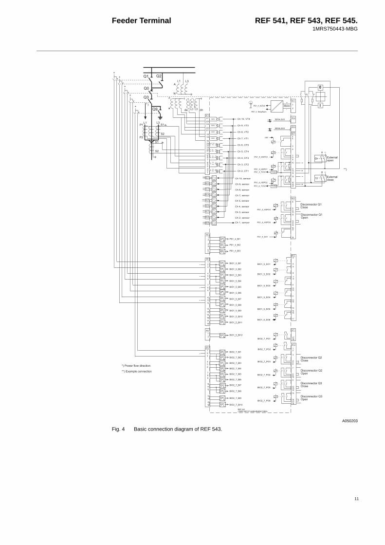
Fig. 4 Basic connection diagram of REF 543.
'
(
)
*)
*
+#
+#
(
*
)
*
)
)
*
(
(
(
()
(
(
(
(*
,
,
,
,
,
,
,
())
.
(
( ,
*
(
*
(*
(*
)
*
)
(*
*
)
)
*
)
*
)*
(
*
)
*
()
(
( ,
-
/00/%)
/00/%/00+#
/00/%
/00/%
/00%
/00+#
/00/%
/00$
/00$)
/00$
/00+123452
) *.$$$#$
$%0*0$
$%0*0$
$%0*0$*
$%0*0$
$%0*0$
$%0*0$
$%0*0$)
$%0*0$
$%0*0$
$%0*0$
$%0*0/%
$%0*0/%
$%0*0/%)
$%0*0/%
$%0*0/%
$%0*0/%
$%00$
$%00$
$%00$
$%00$
$%00$*
$%00$
$%00$
$%00$
$%00$)
$%00$
$%00$
$%00$
$%00%
$%00%
$%00%)
$%00%
$%00%
$%00%
/00#64
()
/
/
7)7
7)7
8
-
-
9 9
9
-
-
-
9)
9 :
.
.
.
.
.
-
-
::
7$
#< ';1;!5
#<';1;!5
#< ';1;!5
#<*';1;!5
,6;!1=!59#4!;1
,6;!1=!59%31
6;
:/!>154!>651=6!
,6;!1=!59)#4!;1
,6;!1=!59)%31
,6;!1=!59#4!;1
,6;!1=!59%31
#<';1;!5
#<)';1;!5
#<';1;!5
#<';1;!5
#<';1;!5
#<'#+
#<)'#+
#<'#+)
#<'#+
#<'#+
#<*'+
#< '+
#< '+)
#<'+
=1544!;1
=154!31
::2341!1=6!
7$

Feeder Terminal REF 541, REF 543, REF 545.1MRS750443-MBG
A050204
Fig. 5 Basic connection diagram of REF 545.
'
(
)
*)
*
+#
+#
(
*
)
*
)
(
(
(
()
(
(
(
(*
,
,
,
,
,
,
,
())
-
.
(
)
*
)
*
)
*
)*
(
(
(
*
)
*
)
*
(*
(*
)
*
) (*
*
)
)
*
)
*
)*
(
(
*
)
*
()
( ,
( ,
$%0*0$
$%0*0$
$%0*0$*
$%0*0$
$%0*0$
$%0*0$
$%0*0$)
$%0*0$
$%0*0$
$%0*0$
$%00$
$%00$
$%00$
$%00$
$%00$*
$%00$
$%00$
$%00$
$%00$)
$%00$
$%00$
$%00$
$%00$
$%00$
$%00$
$%00$
$%00$*
$%00$
$%00$
$%00$
$%00$)
$%00$
$%00$
$%00$
$%0*0/%
$%0*0/%
$%0*0/%)
$%0*0/%
$%0*0/%
$%0*0/%
$%00%
$%00%
$%00%)
$%00%
$%00%
$%00%
$%00%
$%00%
$%00%)
$%00%
$%00%
$%00%
/00/%)
/00/%/00+#
/00/%
/00+#
/00/%:
/00/%
/00/%
/00/%*
/00/%
/00+123452
)).$$$#$
()
/
/
7)7
7)7
8
-
-
9 9
9-
-
-
9)
9 :
.
.
.
.
.
-
-
7$
6;
#< ';1;!5
#<';1;!5
#< ';1;!5
#<*';1;!5
,6;!1=!59#4!;1
,6;!1=!59%31
,6;!1=!59%31
,6;!1=!59#4!;1
:/!>154!>651=6!
,6;!1=!59)#4!;1
,6;!1=!59)%31
#<';1;!5
#<)';1;!5
#<';1;!5
#<';1;!5
#<';1;!5
#<'#+
#<)'#+
#<'#+)
#<'#+
#<'#+
#<*'+
#< '+
#< '+)
#<'+
/00#64
=154!31
=1544!;1
::
7$
12

Feeder Terminal REF 541, REF 543, REF 545.1MRS750443-MBG
13
A050205
Fig. 6 Terminal diagram of the RTD/analog module
Auxiliary voltageFor its operation, the REF 54_ terminal, including the external display module, requires a secured auxiliary voltage supply. The feeder terminal’s internal power supply module forms the voltages required by the feeder terminal electronics. The power supply module is a galvanically isolated (fly-back type) dc/dc converter. A green protection LED indicator on the front panel is lit when the power supply module is in operation.
The feeder terminal is provided with a 48-hour capacitor back-up protection that enables the internal clock to keep time in case of an auxiliary power failure.
Power supplyThere are two basic types of power supply modules available for the REF 54_: type PS1/_ and type PS2/_. See Tecnical data table 9.The operating range of digital inputs depends on the type of the power supply module. See Technical data table 10.
(
+,00,
+,00,
+,00),
+,00,
+,00,
(
*
)
+,00,
+,00*,
+,00 ,
)
*
(
*
)
)
*
-.
-.
-.
-.
8+
8+
8+
8+
8+
8+
8+
8+
.
-
.
-
.
-
.
-
+,00%2
-.
+,00%2
-.
+,00%)2
-.
+,00%2
-.

Feeder Terminal REF 541, REF 543, REF 545.1MRS750443-MBG
Technical data .
Table 1: General functionsFunction DescriptionINDRESET Resetting of operation indicators, latched output signals, registers
and waveforms i.e. the disturbance recorderMMIWAKE Activation of HMI backlightSWGRP1 Switchgroup SWGRP1SWGRP2 Switchgroup SWGRP2SWGRP3 Switchgroup SWGRP3... ...SWGRP20 Switchgroup SWGRP20
Table 2: Standard functionsFunction DescriptionABS Absolute valueACOS Principal arc cosineADD Extensible adderAND Extensible AND connectionASIN Principal arc sineATAN Principal arc tangentBITGET Get one bitBITSET Set one bitBOOL_TO_* Type conversion from BOOL to WORD / USINT / UINT / UDINT /
SINT / REAL / INT / DWORD / DINT / BYTEBOOL2INT Type conversion from BOOL inputs to INT output BYTE_TO_* Type conversion from BYTE to WORD / DWORDCOMH Hysteresis comparatorCOS Cosine in radiansCTD Down-counterCTUD Up-down counterCTU Up-counterDATE_TO_UDINT Type conversion from DATE to UDINTDINT_TO_* Type conversion from DINT to SINT / REAL / INTDIV DividerDWORD_TO_* Type conversion from DWORD to WORD / BYTEEQ Extensible comparison to equalEXP Natural exponentialEXPT ExponentiationF_TRIG Falling edge detectorGE Extensible comparison to greater or equalGT Extensible comparison to greaterINT_TO_* Type conversion from INT to REAL / DINTINT2BOOL Type conversion from INT input to BOOL outputsLE Extensible comparison to less or equalLIMIT LimitationLN Natural logarithmLOG Logarithm base 10LT Extensible comparison to lessMAX Extensible maximumMIN Extensible minimumMOD ModuloMOVE MoveMUL Extensible multiplierMUX Extensible multiplexer
14
Feeder Terminal REF 541, REF 543, REF 545.1MRS750443-MBG
15
1) This function is only supported in the feeder terminal revisions of Release 2.0 or later.
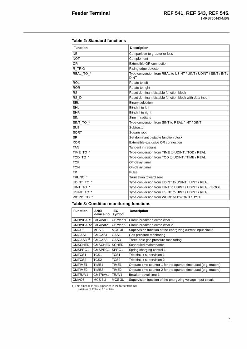
NE Comparison to greater or lessNOT ComplementOR Extensible OR connectionR_TRIG Rising edge detectorREAL_TO_* Type conversion from REAL to USINT / UINT / UDINT / SINT / INT /
DINTROL Rotate to leftROR Rotate to rightRS Reset dominant bistable function blockRS_D Reset dominant bistable function block with data inputSEL Binary selectionSHL Bit-shift to leftSHR Bit-shift to rightSIN Sine in radiansSINT_TO_* Type conversion from SINT to REAL / INT / DINTSUB SubtractorSQRT Square rootSR Set dominant bistable function blockXOR Extensible exclusive OR connectionTAN Tangent in radiansTIME_TO_* Type conversion from TIME to UDINT / TOD / REALTOD_TO_* Type conversion from TOD to UDINT / TIME / REALTOF Off-delay timerTON On-delay timerTP PulseTRUNC_* Truncation toward zeroUDINT_TO_* Type conversion from UDINT to USINT / UINT / REALUINT_TO_* Type conversion from UINT to USINT / UDINT / REAL / BOOLUSINT_TO_* Type conversion from USINT to UINT / UDINT / REALWORD_TO_* Type conversion from WORD to DWORD / BYTE
Table 3: Condition monitoring functionsFunction ANSI
device no.IEC symbol
Description
CMBWEAR1 CB wear1 CB wear1 Circuit-breaker electric wear 1CMBWEAR2 CB wear2 CB wear2 Circuit-breaker electric wear 2CMCU3 MCS 3I MCS 3I Supervision function of the energizing current input circuitCMGAS1 CMGAS1 GAS1 Gas pressure monitoringCMGAS3 1) CMGAS3 GAS3 Three-pole gas pressure monitoring CMSCHED CMSCHED SCHED Scheduled maintenanceCMSPRC1 CMSPRC1 SPRC1 Spring charging control 1CMTCS1 TCS1 TCS1 Trip circuit supervision 1CMTCS2 TCS2 TCS2 Trip circuit supervision 2CMTIME1 TIME1 TIME1 Operate time counter 1 for the operate time used (e.g. motors)CMTIME2 TIME2 TIME2 Operate time counter 2 for the operate time used (e.g. motors)CMTRAV1 CMTRAV1 TRAV1 Breaker travel time 1CMVO3 MCS 3U MCS 3U Supervision function of the energizing voltage input circuit
Table 2: Standard functionsFunction Description

Feeder Terminal REF 541, REF 543, REF 545.1MRS750443-MBG
.
1) This function is only supported in the feeder terminal revisions of Release 2.0 or later.
Table 4: Control functionsFunction ANSI
device no.IEC symbol Description
CO3DC1 CO3DC1 I<->O 3DC1 Three-state disconnector (1) with indicationCO3DC2 CO3DC2 I<->O 3DC2 Three-state disconnector (2) with indicationCOCB1 COCB1 I<->O CB1 Circuit breaker 1 control with indicationCOCB2 COCB2 I<->O CB2 Circuit breaker 2 control with indicationCOCBDIR COCBDIR CBDIR Direct open for CBs via HMICODC1 CODC1 I<->O DC1 Disconnector 1 control with indicationCODC2 CODC2 I<->O DC2 Disconnector 2 control with indicationCODC3 CODC3 I<->O DC3 Disconnector 3 control with indicationCODC4 CODC4 I<->O DC4 Disconnector 4 control with indicationCODC5 CODC5 I<->O DC5 Disconnector 5 control with indicationCOIND1 COIND1 I<->O IND1 Switching device 1 indicationCOIND2 COIND2 I<->O IND2 Switching device 2 indication COIND3 COIND3 I<->O IND3 Switching device 3 indicationCOIND4 COIND4 I<->O IND4 Switching device 4 indication COIND5 COIND5 I<->O IND5 Switching device 5 indicationCOIND6 COIND6 I<->O IND6 Switching device 6 indication COIND7 COIND7 I<->O IND7 Switching device 7 indication COIND8 COIND8 I<->O IND8 Switching device 8 indication COLOCAT COLOCAT I<->O POS Logic-controlled control position selectorCOPFC 1) 55 COPFC Power factor controllerCOSW1 COSW1 SW1 On/off switch 1 COSW2 COSW2 SW2 On/off switch 2COSW3 COSW3 SW3 On/off switch 3COSW4 COSW4 SW4 On/off switch 4MMIALAR1 ALARM1 ALARM1 Alarm channel 1, LED indicatorMMIALAR2 ALARM2 ALARM2 Alarm channel 2, LED indicatorMMIALAR3 ALARM3 ALARM3 Alarm channel 3, LED indicatorMMIALAR4 ALARM4 ALARM4 Alarm channel 4, LED indicatorMMIALAR5 ALARM5 ALARM5 Alarm channel 5, LED indicatorMMIALAR6 ALARM6 ALARM6 Alarm channel 6, LED indicatorMMIALAR7 ALARM7 ALARM7 Alarm channel 7, LED indicatorMMIALAR8 ALARM8 ALARM8 Alarm channel 8, LED indicatorMMIDATA1 MMIDATA1 MMIDATA1 MIMIC data monitoring point 1MMIDATA2 MMIDATA2 MMIDATA2 MIMIC data monitoring point 2MMIDATA3 MMIDATA3 MMIDATA3 MIMIC data monitoring point 3MMIDATA4 MMIDATA4 MMIDATA4 MIMIC data monitoring point 4MMIDATA5 MMIDATA5 MMIDATA5 MIMIC data monitoring point 5
16

Feeder Terminal REF 541, REF 543, REF 545.1MRS750443-MBG
17
Power factor controller settings
Power factor controller, COPFCThe number of capacitor banks to be controlledThe relational step sizes and the type of the switching sequence
Size of the first capacitor bank (should be the smallest)Target value for daytime cos ϕDay unitTarget value for night-time cos ϕ Night unitSetting the reconnection inhibit time (discharge time)Sensitivity in the inductive sideSensitivity in the capacitive sideAlarm limit for the maximum reactive powerAlarm limit for the minimum reactive powerOvervoltage limit when the switching in is inhibitedOperation mode
Starting the automatic testing sequenceCalculation methodControl principleDuration demandDay&night switch
Manual command
1...41:1:1:1 linear; 1:1:1:1 circul.; 1:1:2:2 circul.; 1:2:2:2 linear; 1:2:2:2 circul.; 1:2:4:4 linear; 1:2:4:4 circul.; 1:2:4:8 10.0...50000.0 kvar0.70...1.00Inductive; Capacitive0.70...1.00Inductive; Capacitive0.5...6000.0 s60.0...200.0%0.0...100.0%0.1...100.0 Mvar-100.0...0.0 Mvar0.80...1.60 x UnNot in use; Automatic mode; Manual mode; Testing modeNot activated; StartNormal; IntegralProgressive; Direct0.5...6000.0 sNot in use; Digital input; Internal clock; By settingNot activated; Remove one step; Add one step; Disconnect all
Recorded dataNumber of switching operations per dayNumber of switching operations per week
0...655350...65535
Operation accuraciesAccuracy class of operation
±2.0% of set value or ±0.02 x rated value2.0
Table 5: Measurement functionsFunction ANSI
device no.IEC symbol
Description
MEAI1 2) AI1 AI1 General measurement 1 / analog input on RTD/analog moduleMEAI2 2) AI2 AI2 General measurement 2 / analog input on RTD/analog moduleMEAI3 2) AI3 AI3 General measurement 3 / analog input on RTD/analog moduleMEAI4 2) AI4 AI4 General measurement 4 / analog input on RTD/analog moduleMEAI5 2) AI5 AI5 General measurement 5 / analog input on RTD/analog moduleMEAI6 2) AI6 AI6 General measurement 6 / analog input on RTD/analog moduleMEAI7 2) AI7 AI7 General measurement 7 / analog input on RTD/analog moduleMEAI8 2) AI8 AI8 General measurement 8 / analog input on RTD/analog moduleMEAO1 2) AO1 AO1 Analog output 1 on RTD/analog moduleMEAO2 2) AO1 AO1 Analog output 2 on RTD/analog moduleMEAO3 2) AO3 AO3 Analog output 3 on RTD/analog moduleMEAO4 2) AO4 AO4 Analog output 4 on RTD/analog moduleMECU1A Io Io Neutral current measurement, stage AMECU1B Io_B Io_B Neutral current measurement, stage BMECU3A 3I 3I Three-phase current measurement, stage AMECU3B 2) 3I_B 3I_B Three-phase current measurement, stage BMEDREC16 1)
DREC DREC Transient disturbance recorder

Feeder Terminal REF 541, REF 543, REF 545.1MRS750443-MBG
1) These functions are only supported in the feeder termi-nal revisions of Release 1.5 or later
2) These functions are only supported in the feeder termi-nal revisions of Release 2.0 or later.
Measurement function settings
MEFR1 f f System frequency measurementMEPE7 PQE PQE Three-phase power and energy measurementMEVO1A Uo Uo Residual voltage measurement, stage AMEVO1B 2) Uo_B Uo_B Residual voltage measurement, stage BMEVO3A 3U 3U Three-phase voltage measurement, stage AMEVO3B 2) 3U_B 3U_B Three-phase voltage measurement, stage B
Table 5: Measurement functionsFunction ANSI
device no.IEC symbol
Description
General measurement/ analogue input on RTD/analogue module, MEAI1...8 (AI1...AI8)The general measurement function blocks can be used to measure general purpose dc or ac voltage signals with a sensor input. They also include a REAL type input which can be used to monitor any internal REAL type IEC 61131-3 based signal, e.g. input data from the RTD/analogue module.GE1…3 (V dc/ac)General REAL type input
-10000.00000...10000.00000-10000.00000...10000.00000
Neutral current measurement, MECU1A and MECU1B (Io, Io_B)Io (A)Io (%)
0.0…20000.0 A0.0…80.0% In
Three-phase current measurement, MECU3A and MECU3B (3I, 3I_B)IL1 IL2 IL3 IL1 IL2 IL3 IL1 demand IL2 demand IL3 demand IL1 demand IL2 demand IL3 demand
0.0…20000.0 A0.0…20000.0 A0.0…20000.0 A0.0…1000.0% In0.0…1000.0% In0.0…1000.0% In0.0…20000.0 A0.0…20000.0 A0.0…20000.0 A0.0…1000.0% In0.0…1000.0% In0.0…1000.0% In
Transient disturbance recorder for 16 analogue channels, MEDREC16 (DREC)The transient disturbance recorder MEDREC16 is used for recording the current and voltage waveforms, as well as the status data of internal IEC 61131-3 based logic signals and digital inputs connected to the feeder terminals. The maximum number of analogue inputs and logic signals is 16. One fundamental cycle contains 40 samples.Operation mode
Pre-trg timeOver limit ILxOver limit IoOver limit IobOver limit UoOver limit UxOver limit UxyOver limit U12bOver limit ILxbUnder limit UxUnder limit UxyAI filter time
SaturationOverwriteExtension0…100%0.00…40.00 x In0.00…40.00 x In0.00…40.00 x In0.00…2.00 x Un0.00…2.00 x Un0.00…2.00 x Un0.00…2.00 x Un0.00…40.00 x In0.00…2.00 x Un0.00…2.00 x Un0.000…60.000 s
18

Feeder Terminal REF 541, REF 543, REF 545.1MRS750443-MBG
19
Analogue output on RTD/analogue module, MEAO1...4 (AO1...AO4)The analogue output function blocks handle the scaling of any internal REAL type IEC 61131-3 based signal to fit a selectable 0…20 mA or 4…20 mA range for use with the outputs on the RTD/analogue module.General REAL type input -10000.00000...10000.00000
The recording can be triggered by any (or several) of the alternatives listed below:• triggering on the rising or falling edge of any (or several) of the digital inputs• triggering on overcurrent, overvoltage or undervoltage• manual triggering via the menu or with the push-button F on the front panel (if configured)• triggering via serial communication• periodic triggeringThe recording length depends on the number of recordings and inputs used. For example, the following combination of recording length, number of recordings and number of inputs is available at 50 Hz:# recordings \ # inputs 1 3 101 1163 cyc.
23.2 s412 cyc.8.2 s
126 cyc.2.5 s
5 232 cyc.4.6 s
82 cyc.1.6 s
25 cyc.0.5 s
10 115 cyc.2.3 s
41 cyc.0.8 s
12 cyc.0.24 s
System frequency measurement, MEFR1 (f)FrequencyAverage Freq.Voltage U
10.00…75.00 Hz10.00…75.00 Hz0.0…2.0 x Un
Three-phase power and energy measurement, MEPE7 (PQE)P3 (kW)Q3 (kvar)Power factor DPFPower factor PFP3 demand (kW)Q3 demand (kvar)Energy kWhReverse kWhEnergy kvarhReverse kvarh
-999999…999999 kW-999999…999999 kvar-1.00…1.00-1.00…1.00-999999…999999 kW-999999…999999 kvar0…999999999 kWh0…999999999 kWh0…999999999 kvarh0…999999999 kvarh
Residual voltage measurement, MEVO1A and MEVO1B (Uo, Uo_B)UoUo
0…150000 V0.0…120.0% Un
Three-phase voltage measurement, MEVO3A and MEVO3B (3U, 3U_B)UL1_U12 UL2_U23UL3_U31UL1_U12UL2_U23UL3_U31UL1_U12 averageUL2_U23 averageUL3_U31 average UL1_U12 averageUL2_U23 averageUL3_U31 average
0.00…999.99 kV0.00…999.99 kV0.00…999.99 kV0.00…2.00 x Un0.00…2.00 x Un0.00…2.00 x Un0.00…999.99 kV0.00…999.99 kV0.00…999.99 kV0.00…2.00 x Un0.00…2.00 x Un0.00…2.00 x Un
Feeder Terminal REF 541, REF 543, REF 545.1MRS750443-MBG
1) These functions are only supported in the feeder termi-nal revisions of Release 1.5 or later.
2) These functions are only supported in the feeder termi-nal revisions of Release 2.0 or later.
3) These functions are only supported in the feeder termi-nal revisions of Release 2.5 or later.
4) This function is only supported in the feeder terminal revisions of Release 3.5 or later.
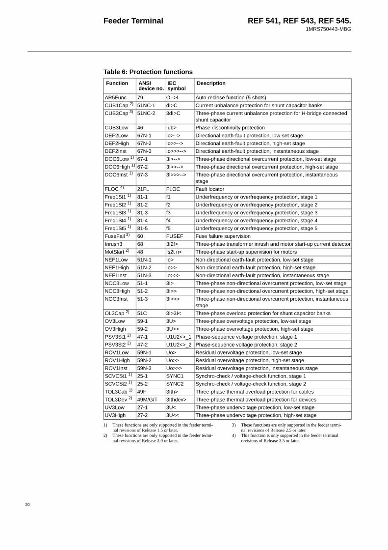
Table 6: Protection functionsFunction ANSI
device no.IEC symbol
Description
AR5Func 79 O-->I Auto-reclose function (5 shots)CUB1Cap 2) 51NC-1 dI>C Current unbalance protection for shunt capacitor banksCUB3Cap 3) 51NC-2 3dI>C Three-phase current unbalance protection for H-bridge connected
shunt capacitorCUB3Low 46 Iub> Phase discontinuity protectionDEF2Low 67N-1 Io>--> Directional earth-fault protection, low-set stageDEF2High 67N-2 Io>>--> Directional earth-fault protection, high-set stageDEF2Inst 67N-3 Io>>>--> Directional earth-fault protection, instantaneous stageDOC6Low 1) 67-1 3I>--> Three-phase directional overcurrent protection, low-set stageDOC6High 1) 67-2 3I>>--> Three-phase directional overcurrent protection, high-set stageDOC6Inst 1) 67-3 3I>>>--> Three-phase directional overcurrent protection, instantaneous
stageFLOC 4) 21FL FLOC Fault locatorFreq1St1 1) 81-1 f1 Underfrequency or overfrequency protection, stage 1Freq1St2 1) 81-2 f2 Underfrequency or overfrequency protection, stage 2Freq1St3 1) 81-3 f3 Underfrequency or overfrequency protection, stage 3Freq1St4 1) 81-4 f4 Underfrequency or overfrequency protection, stage 4Freq1St5 1) 81-5 f5 Underfrequency or overfrequency protection, stage 5FuseFail 3) 60 FUSEF Fuse failure supervisionInrush3 68 3I2f> Three-phase transformer inrush and motor start-up current detectorMotStart 2) 48 Is2t n< Three-phase start-up supervision for motorsNEF1Low 51N-1 Io> Non-directional earth-fault protection, low-set stageNEF1High 51N-2 Io>> Non-directional earth-fault protection, high-set stageNEF1Inst 51N-3 Io>>> Non-directional earth-fault protection, instantaneous stageNOC3Low 51-1 3I> Three-phase non-directional overcurrent protection, low-set stageNOC3High 51-2 3I>> Three-phase non-directional overcurrent protection, high-set stageNOC3Inst 51-3 3I>>> Three-phase non-directional overcurrent protection, instantaneous
stageOL3Cap 2) 51C 3I>3I< Three-phase overload protection for shunt capacitor banksOV3Low 59-1 3U> Three-phase overvoltage protection, low-set stageOV3High 59-2 3U>> Three-phase overvoltage protection, high-set stagePSV3St1 2) 47-1 U1U2<>_1 Phase-sequence voltage protection, stage 1PSV3St2 2) 47-2 U1U2<>_2 Phase-sequence voltage protection, stage 2ROV1Low 59N-1 Uo> Residual overvoltage protection, low-set stageROV1High 59N-2 Uo>> Residual overvoltage protection, high-set stageROV1Inst 59N-3 Uo>>> Residual overvoltage protection, instantaneous stageSCVCSt1 1) 25-1 SYNC1 Synchro-check / voltage-check function, stage 1SCVCSt2 1) 25-2 SYNC2 Synchro-check / voltage-check function, stage 2TOL3Cab 1) 49F 3Ith> Three-phase thermal overload protection for cablesTOL3Dev 2) 49M/G/T 3Ithdev> Three-phase thermal overload protection for devicesUV3Low 27-1 3U< Three-phase undervoltage protection, low-set stageUV3High 27-2 3U<< Three-phase undervoltage protection, high-set stage
20

Feeder Terminal REF 541, REF 543, REF 545.1MRS750443-MBG
21
Settings of protection functions
Three-phase non-directional overcurrent protection, low-set stage, NOC3Low, 3I> (51-1)Start currentOperate time at DT modeTime multiplier at IDMT modeOperation mode
Measuring mode
Drop-off time of the operate time counter
0.10…5.00 x In0.05…300.00 s0.05…1.00Not in useDefinite time Extremely inverseVery inverseNormal inverseLong time inverseRI-type inverseRD-type inverseIEEE Extremely inverseIEEE Very inverseIEEE Short time inverseIEEE Short time extremely inverseIEEE Long time extremely inverseIEEE Long time very inverseIEEE Long time inversePeak-to-peakFundamental frequency0...1000 ms
Operation accuracyStart time
Reset time
Reset ratio, typicallyRetardation timeOperate time accuracy at DT modeAccuracy class index E at IDMT mode
Note! The values below apply when f/fn = 0.95...1.05±2.5% of set value or ±0.01 x InInjected currents > 2.0 x start current:internal time < 32 ms total time < 40 ms40...1000 ms (depends on the minimum pulse width set for the trip output)0.95< 45 ms±2% of set value or ±20 msClass index E = 5.0 or ±20 ms
Three-phase non-directional overcurrent protection, high-set stage, NOC3High, 3I>> (51-2) and instantaneous stage, NOC3Inst, 3I>>> (51-3)Start currentOperate timeOperation mode
Measuring mode
Drop-off time of the operate time counter
0.10…40.00 x In0.05…300.00 sNot in useDefinite timeInstantaneous
Peak-to-peakFundamental frequency0...1000 ms
Operation accuracy
Start time
Reset time
Reset ratio, typicallyRetardation timeOperate time accuracy at DT mode
Note! The values below apply when f/fn = 0.95...1.050.1...10 x In: ±2.5% of set value or ±0.01 x In10...40 x In: ±5.0% of set valueInjected currents > 2.0 x start current:internal time < 32 mstotal time < 40 ms40...1000 ms (depends on the minimum pulse width set for the trip output)0.95< 45 ms±2% of set value or ±20 ms

Feeder Terminal REF 541, REF 543, REF 545.1MRS750443-MBG
Three-phase directional O/C function, low-set stage, DOC6Low, 3I>→ (67-1)Operation mode
Start currentOperate timeTime multiplierBasic angle ϕbOperation direction
Earth-fault protection
Measuring mode
Drop-off time of the operate time counter
Not in use;Definite timeExtremely inv.;Very inverseNormal inverseLong-time inv.;RI-type inverseRD-type inverse0.05…40.00 x In0.05…300.00 s0.05…1.000…90°ForwardReverseDisabledEnabledPhase-to-phase voltages, peak-to-peak measurementPhase-to-phase voltages, fundamental freq. measurementPhase-to-earth voltages, peak-to-peak measurementPhase-to-earth voltages, fundamental freq. measurement0...1000 ms
Operation accuracy
Start time
Reset time
Reset ratio, typicallyRetardation timeOperate time accuracy at DT modeAccuracy class index E at IDMT mode
Note! The values below apply when f/fn = 0.95...1.050.1...10 x In: ±2.5% of set value or ±0.01 x In10...40 x In: ±5.0% of set value±2.5% of measured voltage or ±0.01 x Un±2°Injected currents > 2.0 x start current:internal time < 42 ms total time < 50 ms40...1000 ms (depends on the minimum pulse width set for the trip output)0.95< 45 ms±2% of set value or ±20 msClass index E = 5.0 or ±20 ms
Three-phase directional O/C function, high-set stage, DOC6High, I>>→ (67-2), and instantaneous stage, DOC6Inst, I>>>→ (67-3)Operation mode
Start currentOperate timeBasic angle ϕbOperation direction
Earth-fault protection
Non-directional operation (when the direction cannot be determined)Measuring mode
Drop-off time of the operate time counter
Not in useDefinite timeInstantaneous0.05…40.00 x In0.05…300.00 s0…90°ForwardReverseDisabledEnabledDisabledEnabledPhase-to-phase voltages, peak-to-peak measurementPhase-to-phase voltages, fundamental freq. measurementPhase-to-earth voltages, peak-to-peak measurementPhase-to-earth voltages, fundamental freq. measurement0...1000 ms
22
Feeder Terminal REF 541, REF 543, REF 545.1MRS750443-MBG
23
Operation accuracy
Start time
Reset time
Reset ratio, typicallyRetardation timeOperate time accuracy at DT mode
Note! The values below apply when f/fn = 0.95...1.050.1...10 x In: ±2.5% of set value or ±0.01 x In10...40 x In: ±5.0% of set value±2.5% of measured voltage or ±0.01 x Un±2°Injected currents > 2.0 x start current:internal time < 42 ms total time < 50 ms40...1000 ms (depends on the minimum pulse width set for the trip output)0.95< 45 ms±2% of set value or ±20 ms
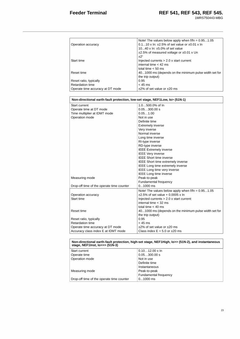
Non-directional earth-fault protection, low-set stage, NEF1Low, Io> (51N-1)Start currentOperate time at DT modeTime multiplier at IDMT modeOperation mode
Measuring mode
Drop-off time of the operate time counter
1.0…500.0% of In0.05…300.00 s0.05…1.00Not in useDefinite timeExtremely inverseVery inverseNormal inverseLong time inverseRI-type inverseRD-type inverseIEEE Extremely inverseIEEE Very inverseIEEE Short time inverseIEEE Short time extremely inverseIEEE Long time extremely inverseIEEE Long time very inverseIEEE Long time inversePeak-to-peakFundamental frequency0...1000 ms
Operation accuracyStart time
Reset time
Reset ratio, typicallyRetardation timeOperate time accuracy at DT modeAccuracy class index E at IDMT mode
Note! The values below apply when f/fn = 0.95...1.05±2.5% of set value + 0.0005 x InInjected currents > 2.0 x start current:internal time < 32 mstotal time < 40 ms40...1000 ms (depends on the minimum pulse width set for the trip output)0.95< 45 ms±2% of set value or ±20 msClass index E = 5.0 or ±20 ms
Non-directional earth-fault protection, high-set stage, NEF1High, Io>> (51N-2), and instantaneous stage, NEF1Inst, Io>>> (51N-3)Start currentOperate timeOperation mode
Measuring mode
Drop-off time of the operate time counter
0.10…12.00 x In0.05…300.00 sNot in useDefinite timeInstantaneousPeak-to-peakFundamental frequency0...1000 ms
Feeder Terminal REF 541, REF 543, REF 545.1MRS750443-MBG
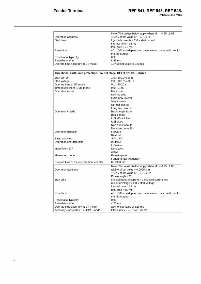
Operation accuracyStart time
Reset time
Reset ratio, typicallyRetardation timeOperate time accuracy at DT mode
Note! The values below apply when f/fn = 0.95...1.05±2.5% of set value or + 0.01 x InInjected currents > 2.0 x start current:internal time < 32 mstotal time < 40 ms40...1000 ms (depends on the minimum pulse width set for the trip output)0.95< 45 ms±2% of set value or ±20 ms
Directional earth-fault protection, low-set stage, DEF2Low, Io>→ (67N-1)Start currentStart voltageOperate time at DT modeTime multiplier at IDMT modeOperation mode
Operation criteria
Operation direction
Basic angle ϕbOperation characteristic
Intermittent E/F
Measuring mode
Drop-off time of the operate time counter
1.0…500.0% of In2.0…100.0% of Un0.1…300.0 s0.05…1.00Not in useDefinite timeExtremely inverseVery inverseNormal inverseLong time inverseBasic angle & UoBasic angleIoSin/Cos & UoIoSin/CosNon-directional IoNon-directional UoForwardReverse-90°... 60°IoSin(ϕ)IoCos(ϕ)Not activeActivePeak-to-peakFundamental frequency0...1000 ms
Operation accuracy
Start time
Reset time
Reset ratio, typicallyRetardation timeOperate time accuracy at DT modeAccuracy class index E at IDMT mode
Note! The values below apply when f/fn = 0.95...1.05±2.5% of set value + 0.0005 x In±2.5% of set value or + 0.01 x UnPhase angle ±2°Injected neutral current > 2.0 x start current andresidual voltage > 2.0 x start voltage:internal time < 72 mstotal time < 80 ms40...1000 ms (depends on the minimum pulse width set for the trip output)0.95< 50 ms±2% of set value or ±20 msClass index E = 5.0 or ±20 ms
24

Feeder Terminal REF 541, REF 543, REF 545.1MRS750443-MBG
25
Directional earth-fault protection, high-set stage, DEF2High, Io>>→ (67N-2), and instantaneous stage, DEF2Inst, Io>>>→ (67N-3)Start currentStart voltageOperate timeOperation mode
Operation criteria
Operation direction
Basic angle ϕbOperation characteristic
Intermittent E/F
Measuring mode
Drop-off time of the operate time counter
1.0…500.0% of In2.0…100.0% of Un0.1…300.0 sNot in useDefinite timeInstantaneousBasic angle & UoBasic angleIoSin/Cos & UoIoSin/CosNon-directional IoNon-directional UoForwardReverse-90°... 60°IoSin(ϕ)IoCos(ϕ)Not activeActivePeak-to-peakFundamental frequency0...1000 ms
Operation accuracy
Start time
Reset time
Reset ratio, typicallyRetardation timeOperate time accuracy at DT mode
Note! The values below apply when f/fn = 0.95...1.05±2.5% of set value + 0.0005 x In±2.5% of set value or + 0.01 x UnPhase angle ±2°Injected neutral current > 2.0 x start currentand residual voltage > 2.0 x start voltage:internal time < 72 mstotal time < 80 ms40...1000 ms (depends on the minimum pulse width set for the trip output)0.95< 50 ms±2% of set value or ±20 ms
Residual overvoltage protection, low-set stage, ROV1Low, Uo> (59N-1)Start voltageOperate timeOperation mode
Measuring mode
2.0…100.0% of Un0.05…300.00 sNot in useDefinite timePeak-to-peakFundamental frequency
Operation accuracyStart time
Reset time
Reset ratio, typicallyRetardation time
Operate time accuracy at DT mode
Note! The values below apply when f/fn = 0.95...1.05±2.5% of set value or ±0.01 x UnInjected voltages >2 x start voltage:internal time < 32 mstotal time < 40 ms40...1000 ms (depends on the minimum pulse width set for the trip output)0.95Total time for blocking: < 25 msTotal time when voltage drops below start value: < 50 ms±2% of set value or ±20 ms

Feeder Terminal REF 541, REF 543, REF 545.1MRS750443-MBG
Residual overvoltage protection, high-set stage, ROV1High, Uo>> (59N-2), and instantaneous stage, ROV1Inst, Uo>>> (59N-3)Start voltageOperate timeOperation mode
Measuring mode
2.0…100.0% of Un0.05…300.00 sNot in useDefinite timePeak-to-peakFundamental frequency
Operation accuracyStart time
Reset time
Reset ratio, typicallyRetardation time
Operate time accuracy at DT mode
Note! The values below apply when f/fn = 0.95...1.05±2.5% of set value or ±0.01 x UnInjected voltages >2 x start voltage:internal time < 32 mstotal time < 40 ms40...1000 ms (depends on the minimum pulse width set for the trip output)0.95Total time for blocking: < 25 msTotal time when voltage drops below start value: < 50 ms±2% of set value or ±20 ms
Three-phase thermal overload protection for cables, TOL3Cab, 3Ith> (49F)Time constant for the cableMaximum load current for the cableMaximum temperature of conductorReference temperatureTrip temperaturePrior alarm temperatureReclosure temperatureAmbient temperatureOperation mode (principle of ambient temperature compensation)
1…999 min1.0…5000.0 A40.0…150.0°C-50.0…100.0°C80.0…120.0%40.0…100.0%40.0…100.0%-50.0…100.0°CNot in useNo sensors; the set ambient temperature1 sensor used2 sensors used
Operation accuracyReset ratio
Note! The values below apply when f/fn = 0.95...1.05±1.0%, I = 0.1...10.0 x InTrip: (Calculated temp. rise - 0.1) / Trip temperatureStart: (Calculated temp. rise - 0.1) / Prior alarm temperature
26

Feeder Terminal REF 541, REF 543, REF 545.1MRS750443-MBG
27
Three-phase thermal overload protection for motors, generators and transformers, TOL3Dev, 3Ithdev> (49M/G/T)BASIC SETTINGSStarting current of the motorMax. starting time permitted for the motorNumber of starts allowed from cold stateType of device to be protected
Trip temperaturePrior alarm temperatureRestart inhibit (temperature limit for successful restarting)Ambient temperatureCooling time-constantHeating time-constant for generator or transformer
0.10...10.00 x In0.1...120.0 s1...3Motor; through-ventilated, rated power < 1500 kWMotor; through-ventilated, rated power > 1500 kWMotor; surface cooling, rated power < 500 kWMotor; surface cooling, rated power > 500 kWGenerator; hydro or small air-cooled turbine generatorsGenerator; large turbine generatorsTransformer80.0…120.0%40.0…100.0%
40.0…100.0%-50.0…100.0°C1.0...10.0 x time constant
1...999 minADVANCED SETTINGSShort time-constant for statorLong time-constant for statorWeighting factor of the short time-constant for statorTemperature rise of stator at rated currentMaximum temperature of statorShort time-constant for rotorLong time-constant for rotorWeighting factor of the short time-constant for rotorTemperature rise of rotor at rated currentMaximum temperature of rotor
0.0...999.0 min0.0...999.0 min
0.00...1.00
0.0...350.0 °C0.0...350.0 °C0.0...999.0 min0.0...999.0 min
0.00...1.00
0.0...350.0 °C0.0...350.0 °C
Operation mode (principle of ambient temperature compensation)
Waiting time for a successful restart (Read-only parameter)Predicted time to the trip (Read-only parameter)
Not in useNo sensors; the set ambient temperature1 sensor used2 sensors used
0...99999 s
0...99999 s
Operation accuracyReset ratio
Note! The values below apply when f/fn = 0.95...1.05±1.0%, I = 0.1...10.0 x InTrip: (Calculated temp. rise - 0.1) / Trip temperatureStart: (Calculated temp. rise - 0.1) / Prior alarm temperatureRestart: (Calculated temp. rise - 0.1) / Restart inhibit temperature limit

Feeder Terminal REF 541, REF 543, REF 545.1MRS750443-MBG
Three-phase overvoltage protection, low-set stage, OV3Low, 3U> (59-1)Start voltageOperate timeTime multiplierOperation mode
Measuring mode
Operation hysteresis
0.10…1.60 x Un0.05…300.00 s0.05…1.00Not in useDefinite timeA curveB curvePhase-to-phase voltages; peak-to-peak measurementPhase-to-phase voltages; fundamental freq. measurementPhase-to-earth voltages; fundamental freq. measurement1.0...5.0%
Operation accuracyStart time
Reset time
Reset ratioRetardation timeOperate time accuracy at DT modeAccuracy class index E at IDMT mode, typically
Note! The values below apply when f/fn = 0.95...1.05 ±35 msInjected voltages = 1.1 x start voltage:internal time < 42 mstotal time < 50 ms40...1000 ms (depends on the minimum pulse width set for the trip output)0.96 (range0.95...0.99)< 50 ms±2% of set value or ±20 ms±20 ms
Three-phase overvoltage protection, high-set stage, OV3High, 3U>> (59-2)Start voltageOperate timeOperation mode
Measuring mode
Operation hysteresis
0.10…1.60 x Un0.05…300.00 sNot in useDefinite timePhase-to-phase voltages; peak-to-peak measurementPhase-to-phase voltages; fundamental freq. measurementPhase-to-earth voltages; fundamental freq. measurement1.0...5.0%
Operation accuracyStart time
Reset time
Reset ratioRetardation timeOperate time accuracy at DT mode
Note! The values below apply when f/fn = 0.95...1.05±2.5% of set valueInjected voltages = 1.1 x start voltage:internal time < 42 mstotal time < 50 ms40...1000 ms (depends on the minimum pulse width set for the trip output)0.96 (range 0.95...0.99)< 50 ms±2% of set value or ±20 ms
Three-phase undervoltage protection, low-set stage, UV3Low, 3U< (27-1)Start voltageOperate timeTime multiplierOperation mode
Measuring mode
Operation hysteresis
0.10…1.20 x Un0.1…300.0 s0.1…1.0Not in useDefinite timeC curvePhase-to-phase voltages; peak-to-peak measurementPhase-to-phase voltages; fundamental freq. measurementPhase-to-earth voltages; fundamental freq. measurement1.0...5.0%
28

Feeder Terminal REF 541, REF 543, REF 545.1MRS750443-MBG
29
Operation accuracyStart time
Reset time
Reset ratioRetardation timeOperate time accuracy at DT modeAccuracy class index E at IDMT mode, typically
Note! The values below apply when f/fn = 0.95...1.05±35 msInjected voltages < 0.5 x start voltage:internal time < 32 mstotal time < 40 ms40...1000 ms (depends on the minimum pulse width set for the trip output)1.04 (range 1.01...1.05)< 60 ms±2.5% of set value±35 ms
Three-phase undervoltage protection, high-set stage, UV3High, 3U<< (27-2)Start voltageOperate timeOperation mode
Measuring mode
Operation hysteresis
0.10…1.20 x Un0.1…300.0 sNot in useDefinite timePhase-to-phase voltages; peak-to-peak measurementPhase-to-phase voltages; fundamental freq. measurementPhase-to-earth voltages; fundamental freq. measurement1.0...5.0%
Operation accuracyStart time
Reset time
Reset ratioRetardation timeOperate time accuracy at DT mode
Note! The values below apply when f/fn = 0.95...1.05±2.5% of set value Injected voltages < 0.5 x start voltage:internal time < 32 mstotal time < 40 ms40...1000 ms (depends on the minimum pulse width set for the trip output)1.04 (range 1.01...1.05)< 60 ms±2.5% of set value
Phase-sequence voltage protection, PSV3St1 and PSV3St2, U1 U2< >_1,U1 U2< >_2 (47-1, 47-2)Start value U2>Start value U1<Start value U1>Operate time U2>Operate time U1<Operate time U1>Operation mode
Dir. selection
0.01…1.00 x Un0.01…1.20 x Un0.80…1.60 x Un0.04…60.00 s0.04…60.00 s0.04…60.00 sNot in use; U1< & U2> & U1>; U1< & U2>; U2> & U1>; U1< & U1>; U2>; U1<; U1>Forward; Reverse; Input ROT_DIR

Feeder Terminal REF 541, REF 543, REF 545.1MRS750443-MBG
Operation accuracyTrip time
Reset time
Reset ratio, typically
Retardation timeOperate time accuracy
Note! The values below apply when f/fn = 0.95...1.05± 2.5% of set value or ± 0.01 x UnU2> operation:Injected negative-seq. voltage = 1.1 x start value:internal time < 42 mstotal time < 50 msU1< operation:Injected positive-seq. voltage = 0.50 x start value:internal time < 32 mstotal time < 40 msU1> operation:Injected positive-seq. voltage = 1.1 x start value:internal time < 42 mstotal time < 50 ms70...1030 ms (depends on the minimum pulse width set for the TRIP output)U2> operation: 0.96U1< operation: 1.04U1> operation: 0.99< 45 ms (for all operations)± 2% of set value or ± 20 ms
Underfrequency or overfrequency protection, 5 stages, Freq1St1… Freq1St5, f1 ... f5 (81-1 ... 81-5)Operation mode
Undervoltage limit for blockingStart value for under-/overfrequency prot.Operate time for under-/overfrequency prot.Start value for df/dt protectionOperate time for df/dt protection
Not in usef</f> 1 timerf</f> 2 timersf</f> OR df/dt>f</f> AND df/dt>f</f> OR df/dt<f</f> AND df/dt<0.30…0.90 x Un25.00…75.00 Hz0.10…300.00 s0.2…10.0 Hz/s0.12…300.00 s
Operation accuracy
Start time
Reset time
Operate time accuracy
Under-/overfrequency (f</f>): ±10 mHzFrequency rate of change (df/dt);real df/dt < ±5 Hz/s: ±100 mHz/sreal df/dt < ±15 Hz/s: ±2.0% of real df/dtUndervoltage blocking: ±1.0% of set valueTotal start times at fn = 50 Hz:Frequency measurement < 100 msDf/dt measurement < 120 ms140...1000 ms (depends on the minimum pulse width set for the trip output)±2% of set value or ±30 ms
30

Feeder Terminal REF 541, REF 543, REF 545.1MRS750443-MBG
31
Start-up supervision for motors, MotStart, Is2t n< (48)Start current (for motor)Start time (for motor)Time-based restart inhibit limitCountdown rate of the time counterStalling time permitted for rotorOperation mode
Start counter (Read-only parameter)Time to restart enable (Read-only parameter)Stall input (signal for motor stalling indication; read-only parameter)
1.0...10.0 x In0.3...250.0 s1.0...500.0 s2.0...250.0 s/h2.0...120.0 sNot in useI2tI2t & Stall0...99999 0...99999 min
Not activeActive
Operation accuracyStart time
Reset ratio, typicallyRetardation time
f/fn = 0.95...1.05: ±2.5% of set value or ±0.01 x Inf/fn = 0.95...1.50:internal time < 22 mstotal time < 30 msf/fn = 0.50...0.95:internal time < 32 mstotal time < 40 ms0.95< 50 ms
Three-phase overload protection for shunt capacitor banks, OL3Cap, 3I>3I< (51C)Operate times of the overload stage Ib>I/Ib> t [s] Standard durations [s] Standard1.151.201.30
1.401.702.002.20
179929958
13.50.90.290.1
180030060
1510.30.12
IEC 60871-1IEC 60871-1ANSI/IEEE 37.99, IEC 60871-1ANSI/IEEE 37.99ANSI/IEEE 37.99ANSI/IEEE 37.99ANSI/IEEE 37.99
Note! The minimum operate time is 100 msStart current of trip stageTime multiplier k for trip stageStart current of alarm stageOperate time of alarm stageStart current of undercurrent stageOperate time of undercurrent stageSetting of reconnection inhibit time trec
0.30...1.50 x In0.05...2.00.80...1.20 x Ib0.5...6000.0 s0.10...0.70 x Ib0.1...120 s0.5...6000 s
Operation accuracies
Start time
Reset time
Reset ratio
Retardation time
Operate time accuracy at definite time mode (alarm stage Ia>, undercurrent stage I<)Operate time accuracy at inverse time mode (trip stage Ib>)
Note! The values below apply when f/fn=0.95...1.05 ±2.5% of set value or ±0.01 x InInjected currents = 2.0 x start currentinternal time < 32 mstotal time < 40 ms 40...1000 ms (depends on the minimum pulse width set for the TRIP output)Overload stages: Typ. 0.95Undercurrent stage: Typ. 1.05Total retardation time when the current exceeds the start value: < 50 ms ±2% of set value or ±20 ms
Depends on the frequency of the current measured: ±10% of theoretical value or ±40 ms
Feeder Terminal REF 541, REF 543, REF 545.1MRS750443-MBG
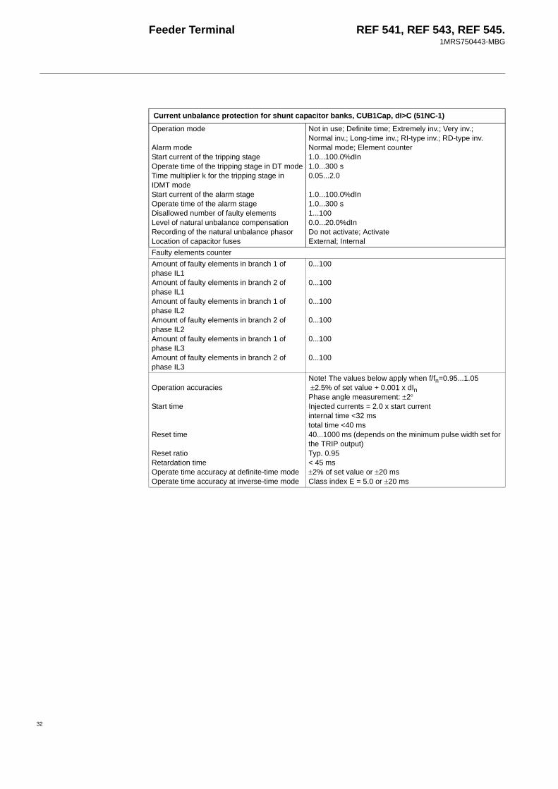
Current unbalance protection for shunt capacitor banks, CUB1Cap, dI>C (51NC-1)Operation mode
Alarm modeStart current of the tripping stageOperate time of the tripping stage in DT modeTime multiplier k for the tripping stage in IDMT modeStart current of the alarm stageOperate time of the alarm stageDisallowed number of faulty elementsLevel of natural unbalance compensationRecording of the natural unbalance phasorLocation of capacitor fuses
Not in use; Definite time; Extremely inv.; Very inv.; Normal inv.; Long-time inv.; RI-type inv.; RD-type inv. Normal mode; Element counter1.0...100.0%dIn1.0...300 s0.05...2.0
1.0...100.0%dIn1.0...300 s1...1000.0...20.0%dInDo not activate; ActivateExternal; Internal
Faulty elements counterAmount of faulty elements in branch 1 of phase IL1Amount of faulty elements in branch 2 of phase IL1Amount of faulty elements in branch 1 of phase IL2Amount of faulty elements in branch 2 of phase IL2Amount of faulty elements in branch 1 of phase IL3Amount of faulty elements in branch 2 of phase IL3
0...100
0...100
0...100
0...100
0...100
0...100
Operation accuracies
Start time
Reset time
Reset ratioRetardation timeOperate time accuracy at definite-time modeOperate time accuracy at inverse-time mode
Note! The values below apply when f/fn=0.95...1.05 ±2.5% of set value + 0.001 x dInPhase angle measurement: ±2°Injected currents = 2.0 x start currentinternal time <32 mstotal time <40 ms40...1000 ms (depends on the minimum pulse width set for the TRIP output) Typ. 0.95 < 45 ms±2% of set value or ±20 ms Class index E = 5.0 or ±20 ms
32

Feeder Terminal REF 541, REF 543, REF 545.1MRS750443-MBG
33
Three-phase current unbalance protection for H-bridge connected shunt capacitor banks, CUB3Cap, 3dI>C (51NC-2)Operation mode
Start current of the tripping stageOperate time of the tripping stage in DT modeTime multiplier k for the tripping stage in IDMT modeStart current of the alarm stageOperate time of the alarm stageComp natural dI1Comp natural dI2Comp natural dI3Rec natural dI
Not in use; Definite time; Extremely inv.; Very inv.; Normal inv.; Long-time inv.; RI-type inv.; RD-type inv. 1.0...100.0% dIn1.0...300 s0.05...2.0
1.0...100.0% dIn1.0...300.0 s0.0...20.0% dIn0.0...20.0% dIn0.0...20.0% dInDo not activate; Rec all phasors; Rec phasor dI1, Rec phasor dI2, Rec phasor dL3
Operation accuracies
Start time
Reset time
Reset ratio, typicallyRetardation timeOperate time accuracy at definite-time modeOperate time accuracy at inverse-time mode
Note! The values below apply when f/fn=0.95...1.05 ±2.5% of set value + 0.0005 x dInPhase angle measurement: ±2°Injected currents = 2.0 x start currentinternal time <32 mstotal time <40 ms40...1000 ms (depends on the minimum pulse width set for the TRIP output) 0.95 < 45 ms±2.5% of set value or 0.1% dIn±2.5% of set value or 0.1% dIn
Auto-reclosure function, AR5Func, O → I (79)Number of reclosuresInitiation mode
AR1, AR2, AR3, AR4 starting line operation mode
AR1 AR2, AR3, AR4 start delayDead timeSynchro-checkDiscriminating time td
0…5TripStartNo operationAR shot initiatedInitiation of AR shot blocked0…10.00 s0.20…300.00 sNot in use; ARSYNC in use0…30.00 s
Operation accuracy ±1% of setting value or ±30 ms
Synchro-check/voltage check function stage 1 and stage 2, SCVCSt1 & SCVCSt2, SYNC1, SYNC2 (25-1, 25-2)Upper threshold voltage UmaxLower threshold voltage UminVoltage difference ∆UPhase angle difference ∆phaseFrequency difference ∆f
0.50…1.00 x Un0.10…0.80 x Un0.02…0.60 x Un5…90°0.02…5.00 Hz
Operation accuracy
Reset timeReset ratioOperate time accuracy
Note! The values below apply when f/fn = 0.95...1.05±2.5% of set value or ±0.01 x Un±10 mHz±2°< 50 ms0.975 x Un±2% of set value or ±20 ms

Feeder Terminal REF 541, REF 543, REF 545.1MRS750443-MBG
1) These functions are only supported in the feeder termi-nal revisions of Release 2.0 or later.
2) This function is only supported in the feeder terminal revisions of Release 3.5 or later
Phase discontinuity protection, CUB3Low, Iub> (46)Start unbalanceOperate timeOperation mode
10.0…95.0%1.0…300.0 sNot in useDefinite time
Operation accuracyStart time
Reset time
Reset ratio, typicallyRetardation time
Operate time accuracy at DT mode
Note! The values below apply when f/fn = 0.95...1.05±2.5% of set value or ±1% unitinternal time < 95 mstotal time < 100 ms40...1000 ms (depends on the minimum pulse width set for the trip output)0.95Total time for blocking: < 25 msTotal time when current drops below start value: < 50 ms±2% of set value or ±50 ms
Fuse failure supervision, FuseFail, FUSEF (60)Ratio U2/U1> 10...50%Ratio I2/I1< 10...50%Operation accuracy When f/fn = 0.98...1.02
±2.0 percentage units (of settings Ratio U2/U1> and Ratio I2/I1<)When f/fn = 0.95...1.05±4.0 percentage units (of settings Ratio U2/U1> and Ratio I2/I1<)
BSOUT activation time (when the task interval is 10 ms)
Injected negative-sequence voltage = 2.00 x Ratio U2/U1> (f/fn=0.98...1.02: < 35 ms (within the same task)
Reset time 20 ms (within the same task)Reset ratio for Ratio U2/U1>: 0.8...0.96
for Ratio I2/I1<: 1.04...1.2
Fault locator, FLOC (21FL)The fault locator function for radial distribution systems. Short-circuit localization in all kinds of distribution networks. Earth fault localizations in effectively earthed networks and in low reactance/low resistance earthed networks.Fault localization accuracy ±2.5% of the line length.
Actual fault localization accuracy depends on the fault and the power system characteristics as described in the FLOC function block manual, section “Result validity indicator for earth faults”.
Table 7: Power quality functionsFunction ANSI
device no.IEC symbol
Description
PQCU3H 1) PQ 3Inf PQ 3Inf Current waveform distortion measurementPQVO3H 1) PQ 3Unf PQ 3Unf Voltage waveform distortion measurementPQVO3Sd 2) PQ 3U<> PQ 3U<> Short duration voltage variations
34

Feeder Terminal REF 541, REF 543, REF 545.1MRS750443-MBG
35
Settings of power quality functions
Current waveform distortion measurement, PQCU3H, PQ 3inf (PQ 3inf)The current waveform distortion measurement PQCU3H is used for measurement and statistical analysis of current waveform distortion. The standards concerning voltage distortion measurement are applied to current distortion measurement in PQCU3H. Data collection and analysis is done according to EN 50160. Measuring principles for individual harmonics and THD are adapted from the International standard IEC 61000-4-7. The American standard IEEE Std 1159 is also partly supported. Analysis can be done for one selected phase current or most distorted phase current can be tracked.Measuring modesMeasurement activationTriggering modeDistortion factor
Not in use; L1; L2; L3; Worst phaseTriggering by: setting parameter, binary input, date & time settingSingle; Continuous; PeriodicTHD; TDD
Monitored valuesTHD (3 sec and 10 min mean values)Harmonic components from 1st to 13th (3 sec mean values)Harmonic components from 2nd to 13th (10 min mean values)
0.0 ... 1000.0%
0.0 ... 1000.0% In
0.0 ... 1000.0% InStatisticsObservation times for statistics
Percentile settingPercentiles for each harmonic and THDFive fixed percentiles (1,5,50,95,99) for one selectable harmonic or THDMaximum values for each harmonic and THDRecorded data
1 hour; 12 hours; 1 day; 2 days; 3 days; 4 days; 5 days; 6 days; 1 week90.0 ... 99.5%
0.0 ... 1000.0% In
0.0 ... 1000.0% In
0.0 ... 1000.0% InOne data set for updating; One data set from the previous observation period
Harmonic limit supervisionLimit for THDLimits for each harmonicRecorded data
0.0 ... 60.0%0.0 ... 40.0% InIf any limit should be exceeded, the whole harmonic set will be recorded during the maximum THD (3 sec values)
Operation criteriaFundamental frequencyFrequency deviation
Amplitude of the fundamental wave
0.9 ... 1.1 Fn≤ 0.5 Hz (difference between max and min values within one second)≥ 1% In
Measurement accuracyMeasured harmonic Im = 1st, ... , 10thMeasured harmonic Im = 11th, ... , 13th
In accordance with IEC 61000-4-7
± 1.0% In, if Im < 10% In; ± 10% Im, if Im ≥ 10% In
Voltage waveform distortion measurement, PQVO3H, PQ 3unf (PQ 3unf)The voltage waveform distortion measurement PQVO3H is used for measurement and statistical analysis of voltage waveform distortion. Data collection and analysis is done according to EN 50160. Measuring principles for individual harmonics and THD are adapted from the International standard IEC 61000-4-7. The American standard IEEE Std 1159 is also partly supported. Analysis can be done for one selected phase or phase-to-phase voltage or most distorted phase or phase-to-phase voltage can be tracked.Measuring modesMeasurement activationTriggering mode
Not in use; L1; L2; L3; Worst phase; L1-L2; L2-L3; L3-L1; Worst mainTriggering by: setting parameter, binary input, date & time settingSingle; Continuous; Periodic
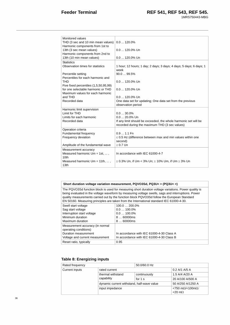
Feeder Terminal REF 541, REF 543, REF 545.1MRS750443-MBG
Monitored valuesTHD (3 sec and 10 min mean values)Harmonic components from 1st to 13th (3 sec mean values)Harmonic components from 2nd to 13th (10 min mean values)
0.0 ... 120.0%
0.0 ... 120.0% Un
0.0 ... 120.0% UnStatisticsObservation times for statistics
Percentile settingPercentiles for each harmonic and THDFive fixed percentiles (1,5,50,95,99) for one selectable harmonic or THDMaximum values for each harmonic and THDRecorded data
1 hour; 12 hours; 1 day; 2 days; 3 days; 4 days; 5 days; 6 days; 1 week90.0 ... 99.5%
0.0 ... 120.0% Un
0.0 ... 120.0% Un
0.0 ... 120.0% UnOne data set for updating; One data set from the previous observation period
Harmonic limit supervisionLimit for THDLimits for each harmonicRecorded data
0.0 ... 30.0%0.0 ... 20.0% UnIf any limit should be exceeded, the whole harmonic set will be recorded during the maximum THD (3 sec values)
Operation criteriaFundamental frequencyFrequency deviation
Amplitude of the fundamental wave
0.9 ... 1.1 Fn≤ 0.5 Hz (difference between max and min values within one second)≥ 0.7 Un
Measurement accuracyMeasured harmonic Um = 1st, ... , 10thMeasured harmonic Um = 11th, ... , 13th
In accordance with IEC 61000-4-7
± 0.3% Un, if Um < 3% Un; ± 10% Um, if Um ≥ 3% Un
Short duration voltage variation measurement, PQVO3Sd, PQ3U< > (PQ3U< >)The PQVO3Sd function block is used for measuring short duration voltage variations. Power quality is being evaluated in the voltage waveform by measuring voltage swells, sags and interruptions. Power quality measurements carried out by the function block PQVO3Sd follow the European Standard EN 50160. Measuring principles are taken from the International standard IEC 61000-4-30.Swell start voltageSag start voltageInterruption start voltageMinimum durationMaximum duration
100.0 … 200.0%0.0 … 100.0%0.0 … 100.0%8 … 60000ms8 … 60000ms
Measurement accuracy (in normal operating conditions)Duration measurementVoltage and current measurement
In accordance with IEC 61000-4-30 Class AIn accordance with IEC 61000-4-30 Class B
Reset ratio, typically 0.95
Table 8: Energizing inputsRated frequency 50.0/60.0 HzCurrent inputs rated current 0.2 A/1 A/5 A
thermal withstand capability
continuously 1.5 A/4 A/20 Afor 1 s 20 A/100 A/500 A
dynamic current withstand, half-wave value 50 A/250 A/1250 Ainput impedance <750 mΩ/<100mΩ/
<20 mΩ
36

Feeder Terminal REF 541, REF 543, REF 545.1MRS750443-MBG
37
Voltage inputs rated voltage 100 V/110 V/115 V/120 V (parameterization)
voltage withstand, continuously 2 x Un (240 V)burden at rated voltage <0.5 VA
Sensor inputs, max 9 AC voltage range 9.4 V RMSDC voltage range ±13.3 Vinput impedance > 4.7 MΩinput capacitance < 1 nF
Table 8: Energizing inputs
Table 9: Auxiliary power suppliesType PS1/240V
(REF 541,REF 543)
PS2/240V(REF 545only)
External displaymodule
PS1/48V(REF 541,REF 543)
PS2/48V(REF 545only)
Input voltage, ac 110/120/220/240 V -Input voltage, dc 110/125/220 V 24/48/60 VVoltage variation ac 85…110%, dc 80…120%
of rated valuedc 80…120% of rated value
Burden <50 WRipple in dc auxiliary voltage max. 12% of the dc valueInterruption time in auxiliary dc voltage without resetting
<40 ms, 110 V and<100 ms, 200 V
<60 ms, 48 V and<100 ms, 60 V
Internal overtemperature indication
+78°C (+75…+83°C)
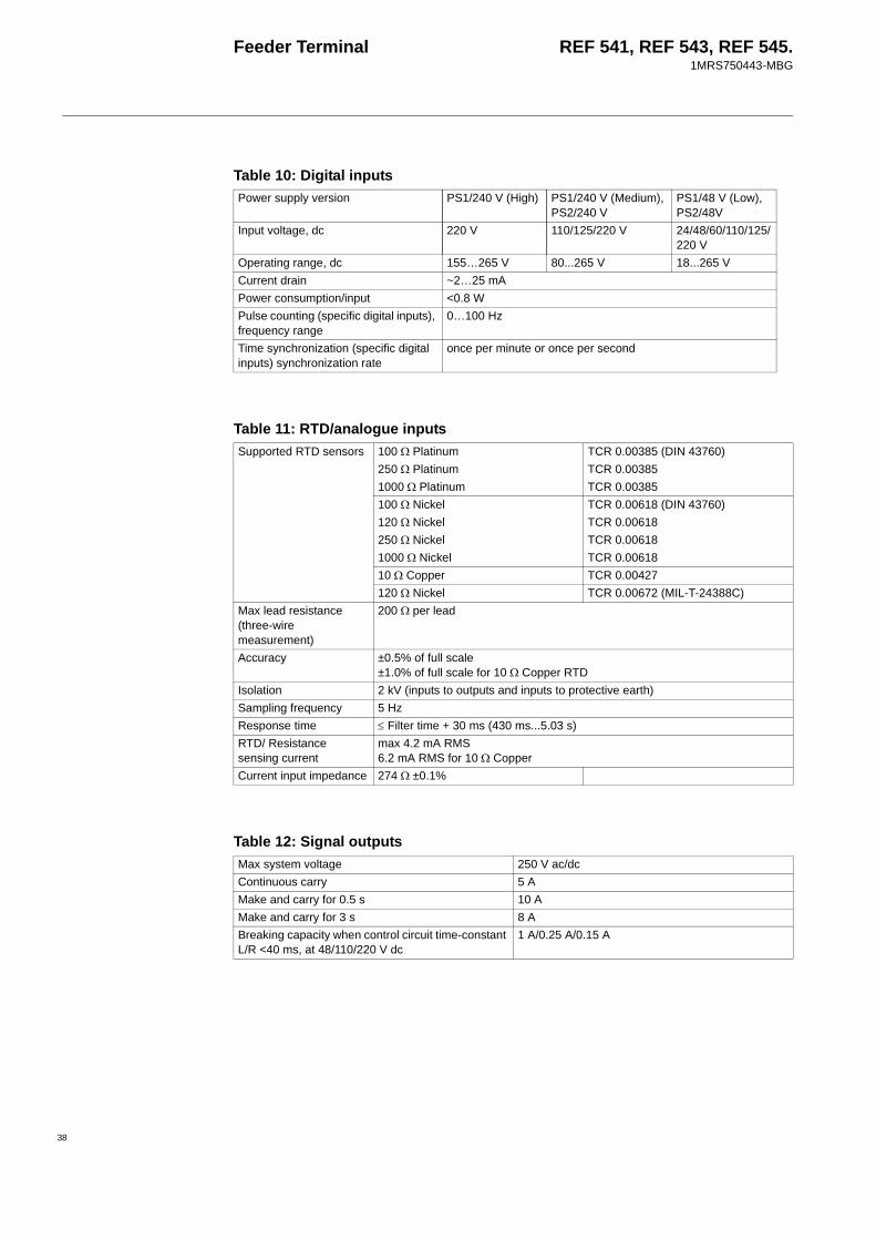
Feeder Terminal REF 541, REF 543, REF 545.1MRS750443-MBG
Table 10: Digital inputsPower supply version PS1/240 V (High) PS1/240 V (Medium),
PS2/240 VPS1/48 V (Low), PS2/48V
Input voltage, dc 220 V 110/125/220 V 24/48/60/110/125/220 V
Operating range, dc 155…265 V 80...265 V 18...265 V Current drain ~2…25 mAPower consumption/input <0.8 WPulse counting (specific digital inputs), frequency range
0…100 Hz
Time synchronization (specific digital inputs) synchronization rate
once per minute or once per second
Table 11: RTD/analogue inputsSupported RTD sensors 100 Ω Platinum TCR 0.00385 (DIN 43760)
250 Ω Platinum TCR 0.003851000 Ω Platinum TCR 0.00385100 Ω Nickel TCR 0.00618 (DIN 43760)120 Ω Nickel TCR 0.00618250 Ω Nickel TCR 0.006181000 Ω Nickel TCR 0.0061810 Ω Copper TCR 0.00427120 Ω Nickel TCR 0.00672 (MIL-T-24388C)
Max lead resistance(three-wire measurement)
200 Ω per lead
Accuracy ±0.5% of full scale ±1.0% of full scale for 10 Ω Copper RTD
Isolation 2 kV (inputs to outputs and inputs to protective earth)Sampling frequency 5 HzResponse time ≤ Filter time + 30 ms (430 ms...5.03 s)RTD/ Resistance sensing current
max 4.2 mA RMS6.2 mA RMS for 10 Ω Copper
Current input impedance 274 Ω ±0.1%
Table 12: Signal outputsMax system voltage 250 V ac/dcContinuous carry 5 AMake and carry for 0.5 s 10 AMake and carry for 3 s 8 ABreaking capacity when control circuit time-constant L/R <40 ms, at 48/110/220 V dc
1 A/0.25 A/0.15 A
38

Feeder Terminal REF 541, REF 543, REF 545.1MRS750443-MBG
39
Table 13: Power outputsMax system voltage 250 V ac/dcContinuous carry 5 AMake and carry for 0.5 s 30 AMake and carry for 3 s 15 ABreaking capacity when control circuit time constant L/R <40 ms, at 48/110/220 V dc
5 A/3 A/1 A
Minimum contact load 100 mA, 24 V ac/dc (2.4 VA)TCS (Trip Circuit Supervision)
Control voltage range 20…265 V ac/dcCurrent drain through the supervision circuit
approx. 1.5 mA (0.99…1.72 mA)
Minimum voltage (threshold) over a contact
20 V ac/dc (15…20 V)
Table 14: Analogue outputsOutput range 0...20 mAAccuracy ±0.5% of full scaleMax load 600 ΩIsolation 2 kV (output to output, output to inputs and output to
protective earth)Response time ≤ 85 ms
Table 15: Environmental conditionsSpecified service temperature range -10…+55°CTransport and storage temperature range -40…+70°CDegree of protection by enclosure Front side, flush-mounted IP 54
Rear side, connection terminals IP 20Dry heat test according to IEC 60068-2-2Dry cold test according to IEC 60068-2-1Damp heat test, cyclic according to IEC 60068-2-30
r.h. = 95%, T = 20°…55°CStorage temperature tests according to IEC 60068-2-48
Table 16: Standard testsInsulation tests Dielectric test
IEC 60255-5Test voltage 2 kV, 50 Hz, 1 min.
Impulse voltage testIEC 60255-5
Test voltage 5 kV, unipolar impulses, waveform 1.2/50 µs, source energy 0.5 J
Insulation resistance measurementsIEC 60255-5
Insulation resistance > 100 MΩ, 500 V dc
Mechanical tests Vibration tests (sinusoidal) IEC 60255-21-1, class IShock and bump test IEC 60255-21-2, class ISeismic test IEC 60255-21-3, class 2

Feeder Terminal REF 541, REF 543, REF 545.1MRS750443-MBG
Table 17: Electromagnetic compatibility testsThe EMC immunity test level fulfills the requirements listed below1 MHz burst disturbance test, class III, IEC 60255-22-1
common mode 2.5 kVdifferential mode 1.0 kV
Electrostatic discharge test, class III, IEC 61000-4-2 and IEC 60255-22-2
for contact discharge 6 kVfor air discharge 8 kV
Radio frequency interference test conducted, common modeIEC 61000-4-6
10 V (rms), f = 150 kHz…80 MHz
radiated, amplitude-modulatedIEC 61000-4-3
10 V/m (rms),f = 80…1000 MHz
radiated, pulse-modulatedENV 50204
10 V/m, f = 900 MHz
radiated, test with a portable transmitterIEC 60255-22-3, method C
f = 77.2 MHz, P = 6 W;f = 172.25 MHz, P = 5 W
Fast transient disturbance test(IEC 60255-22-4 and IEC 61000-4-4)
power supply 4 kVI/O ports 2 kV
Surge immunity test(IEC 61000-4-5)
power supply 4 kV, common mode2 kV, differential mode
I/O ports 2 kV, common mode1 kV, differential mode
Power frequency (50 Hz) magnetic field, IEC 61000-4-8
100 A/m
Voltage dips and short interruptions, IEC 61000-4-11
30%, 10 ms >90%, 5000 ms
Electromagnetic emission testsEN 55011 and EN 50081-2
conducted RF emission (mains terminal)
EN 55011, class A
radiated RF emission EN 55011, class ACE approval Complies with the EMC directive 89/336/EEC and the LV directive
73/23/EEC
40

Feeder Terminal REF 541, REF 543, REF 545.1MRS750443-MBG
41
1) These functions are only supported in the feeder terminal revisions of Release 3.5 or later.
2) These functions are only supported in the feeder terminal revisions of Release 3.0 or later.
Table 18: Data communicationRear interface, connector X3.1 not used, reserved for future purposesRear interface, connector X3.2 RS-232 connection
RER 123 fibre-optic Bus Connection Moduleprotocols SPA, IEC_103, DNP 3.01),
Modbus1)
RER 133 RS-485 Bus Connection Module protocols DNP 3.0 2), Modbus 2)
data transfer rates DNP 3.0 and Modbus:300 bps...19.2 kbps, selectable
SPA-ZC 302 Profibus-DPV1/SPA Gateway protocol Profibus-DPV1 1)
SPA-ZC 400 SPA/ Ethernet Adapter protocol IEC 61850 1)
Rear interface, connector X3.3 RS-485 connectionprotocol SPA, LONthe fibre-optic interface module RER 103 is needed for galvanic isolationdata transfer rates SPA: 4.8/9.6/19.2 kbps,
selectableLON: 78.0 kbps/1.2 Mbps, selectable
Rear interface, connector X3.4 RJ45 connectiongalvanically isolated RJ45 connection for an external display panelprotocol CANcommunication cable 1MRS 120511.001 (1 m)
1MRS 120511.003 (3 m)Front panel optical connection
protocol SPAcommunication cable 1MKC 9500011
SPA protocol bit rates 4.8/9.6/19.2 kbpsstart bits 1data bits 7parity evenstop bits 1
LON protocol bit rates 78.0 kbps/1.2 MbpsIEC_103 protocol bit rates 9.6/19.2 kbps
data bits 8parity evenstop bits 1
DNP 3.0 bit rates 0.3/0.6/1.2/2.4/4.8/9.6/19.2 kbpsdata bits 8stop bits 1, 2parity none, odd, even
Modbus bit rates 0.3/0.6/1.2/2.4/4.8/9.6/19.2 kbpsdata bits 5, 6, 7, 8stop bits 1, 2parity none, odd, even
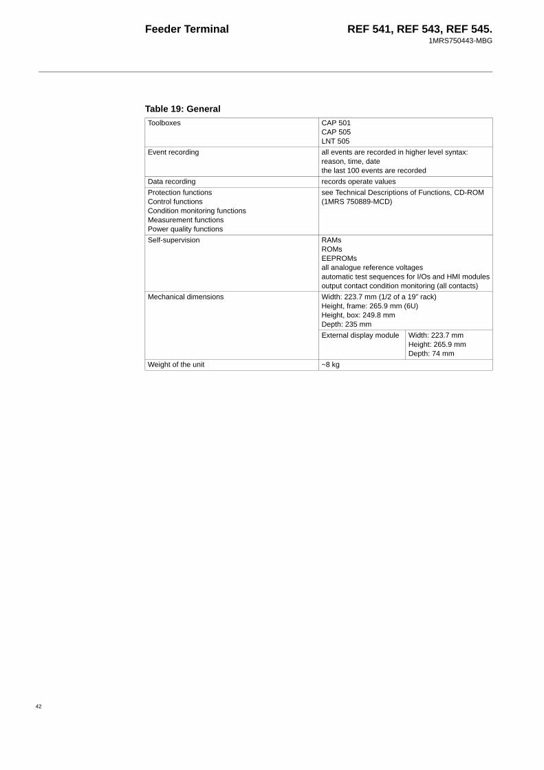
Feeder Terminal REF 541, REF 543, REF 545.1MRS750443-MBG
Table 19: GeneralToolboxes CAP 501
CAP 505LNT 505
Event recording all events are recorded in higher level syntax: reason, time, date the last 100 events are recorded
Data recording records operate valuesProtection functionsControl functionsCondition monitoring functionsMeasurement functionsPower quality functions
see Technical Descriptions of Functions, CD-ROM (1MRS 750889-MCD)
Self-supervision RAMsROMsEEPROMsall analogue reference voltagesautomatic test sequences for I/Os and HMI modulesoutput contact condition monitoring (all contacts)
Mechanical dimensions Width: 223.7 mm (1/2 of a 19” rack)Height, frame: 265.9 mm (6U)Height, box: 249.8 mmDepth: 235 mm External display module Width: 223.7 mm
Height: 265.9 mmDepth: 74 mm
Weight of the unit ~8 kg
42
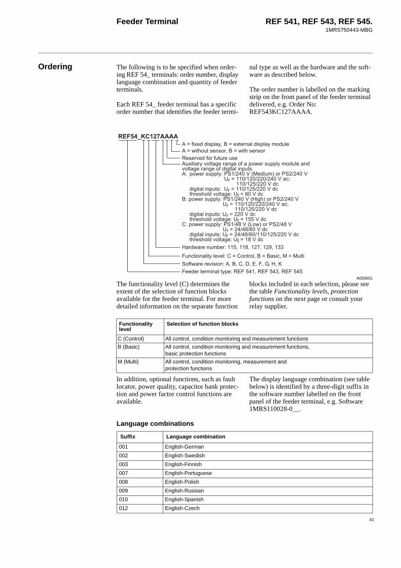
Feeder Terminal REF 541, REF 543, REF 545.1MRS750443-MBG
43
Ordering The following is to be specified when order-ing REF 54_ terminals: order number, display language combination and quantity of feeder terminals.
Each REF 54_ feeder terminal has a specific order number that identifies the feeder termi-
nal type as well as the hardware and the soft-ware as described below.
The order number is labelled on the marking strip on the front panel of the feeder terminal delivered, e.g. Order No: REF543KC127AAAA.
A050601The functionality level (C) determines the extent of the selection of function blocks available for the feeder terminal. For more detailed information on the separate function
blocks included in each selection, please see the table Functionality levels, protection functions on the next page or consult your relay supplier.
In addition, optional functions, such as fault locator, power quality, capacitor bank protec-tion and power factor control functions are available.
The display language combination (see table below) is identified by a three-digit suffix in the software number labelled on the front panel of the feeder terminal, e.g. Software 1MRS110028-0__.
!=>5151?6;6!@'$'#','''A''&1115=15264=B31@')'
5>512C15@' '*' '))
616;34B'$1=1546;34B2!41
6465B?!4=D15D1!3!>15;334B2!41?!4=D15D1!6D6=463=;@ 3!>15;334B@/162!5/
5E 6D6=463=;@5=<51;<!4?!4=D1@=
$@3!>15;334B@/6D<!5/5E
6D6=463=;@5=<51;<!4?!4=D1@=
#@3!>15;334B@/ 7!>!5/ 5 6D6=463=;@5 =<51;<!4?!4=D1@=
>6=<!=;1;!5'$>6=<;1;!51;15?1!5=51;1
=6!46=B41?14@##!=5!4'$$;6'4=6
Functionality level
Selection of function blocks
C (Control) All control, condition monitoring and measurement functionsB (Basic) All control, condition monitoring and measurement functions,
basic protection functionsM (Multi) All control, condition monitoring, measurement and
protection functions
Language combinations
Suffix Language combination
001 English-German002 English-Swedish003 English-Finnish007 English-Portuguese008 English-Polish009 English-Russian010 English-Spanish012 English-Czech

Feeder Terminal REF 541, REF 543, REF 545.1MRS750443-MBG
The REF 541, REF 543 and REF 545 feeder terminals differ from each other as to the number of digital inputs and outputs as fol-lows.
Terminals can optionally be ordered with an ANSI front panel.
The functionality level determines the extent of the selection of function blocks available for the feeder terminal. For more detailed
information on the separate function blocks included in each selection, please consult your relay supplier.
Number of inputs/outputs
Number of inputs/outputs REF 541 REF 543 REF 545
Digital inputs 15 25 34Trip circuit supervision inputs 2 2 2Power outputs (NO single-pole) 0 2 3Power outputs (NO double-pole) 5 9 11Signal outputs (NO) 2 2 4Signal outputs (NO/NC) 5 5 8Self-supervision outputs 1 1 1
Functionality levels, protection functionsFUNCTIONALITY LEVELS
ANSI Code
IEC Symbol
Function Code REF541/3/5 CONTROL
REF541/3/5 BASIC
REF541/3/5 MULTI
SHORT CIRCUITS51-1 3I > Three-phase non-directional
overcurrent, low-set stageNOC3Low X X
51-2 3I >> Three-phase non-dir. overcurrent, high-set stage / blockable overcurrent
NOC3High X X
51-3 3I >>> Three-phase non-dir. overcurrent, inst. stage / blockable overcurrent
NOC3Inst X X
67-1 3I > -> Three-phase directional o/c, low-set stage
DOC6Low X X
67-2 3I >> -> Three-phase directional o/c, high-set stage / blockable overcurrent
DOC6High X X
67-3 3I >>> -> Three-phase directional o/c, high-set stage / blockable overcurrent
DOC6Inst X X
EARTH-FAULTS51N-1 Io > Non-directional earth-fault,
low-set stageNEF1Low X X
51N-2 Io >> Non-directional earth-fault, high-set stage
NEF1High X X
50N-3 Io >>> Non-directional earth-fault, instantaneous stage
NEF1Inst X X
67N-1 Io > -> Directional earth-fault, low-set stage
DEF2Low X X
67N-2 Io >> -> Directional earth-fault, high-set stage
DEF2High X X
67N-3 Io >>> -> Directional earth-fault, instantaneous stage
DEF2Inst X X
59N-1 Uo > Residual overvoltage, low-set stage
ROV1Low X X
59N-2 Uo >> Residual overvoltage, high-set stage
ROV1High X X
44

Feeder Terminal REF 541, REF 543, REF 545.1MRS750443-MBG
45
59N-3 Uo >>> Residual overvoltage, instantaneous stage
ROV1Inst X X
OVERLOAD49F 3Ith> Three-phase thermal
overload (feeders & cables)TOL3Cab X X
OVER / UNDERVOLTAGE59-1 3U > Three-phase overvoltage,
low-set stageOV3Low X
59-2 3U >> Three-phase overvoltage, high-set stage
OV3High X
27-1 3U < Three-phase undervoltage, low-set stage
UV3Low X
27-2 3U << Three-phase undervoltage, high-set stage
UV3High X
Functionality levels, protection functionsFUNCTIONALITY LEVELS
ANSI Code
IEC Symbol
Function Code REF541/3/5 CONTROL
REF541/3/5 BASIC
REF541/3/5 MULTI

Feeder Terminal REF 541, REF 543, REF 545.1MRS750443-MBG
LOAD SHEDDING AND RESTORATION
81-1 f1 Underfrequency or overfrequency inc. rate of change, stage 1
Freq1St1 X
81-2 f2 Underfrequency or overfrequency incl. rate of change, stage 2
Freq1St2 X
81-3 f3t Underfrequency or overfrequency incl. rate of change, stage 3
Freq1St3 X
81-4 f4 Underfrequency or overfrequency incl. rate of change, stage 4
Freq1St4 X
81-5 f5 Underfrequency or overfrequency incl. rate of change, stage 5
Freq1St5 X
ADDITIONAL FUNCTIONS79 O → I Auto-reclosure AR5Func X X X25-1 SYNC1 Synchro-check/voltage
check, stage 1SCVCSt1 X X X
25-2 SYNC2 Synchro-check/voltage check, stage 2
SCVCSt2 X X X
68 3I2f > Three-phase inrush detector Inrush3 X X60 FUSEF Fuse failure supervision FuseFail X X X46 Iub> Phase discontinuity CUB3Low X X62BF CBFP Circuit breaker failure - X X X49M/G/T 3Ithdev> Three-phase thermal
overload protection for devices
TOL3Dev X
48 Is2t n< Start-up supervision for motors
MotStart X
47-1 U1U2<>_1
Three-phase phase-sequency voltage protection, stage 1
PSV3St1 X
47-2 U1U2<>_2
Three-phase phase-sequency voltage protection, stage 2
PSV3St2 X
Functionality levels, protection functionsFUNCTIONALITY LEVELS
ANSI Code
IEC Symbol
Function Code REF541/3/5 CONTROL
REF541/3/5 BASIC
REF541/3/5 MULTI
Functionality levels, other functionsFUNCTIONALITY LEVELS
ANSI Code
IEC Symbol
Function Code REF541/3/5 CONTROL
REF541/3/5 BASIC
REF541/3/5 MULTI
MEASUREMENT FUNCTIONSCURRENT
3I 3I Three-phase current MECU3A X X X3I_B 3I_B Three-phase current, B
stageMECU3B X X X
Io Io Neutral current MECU1A X X XIo_B Io_B Neutral current, B stage MECU1B X X X
VOLTAGE3U 3U Three-phase voltage MEVO3A X X X
46

Feeder Terminal REF 541, REF 543, REF 545.1MRS750443-MBG
47
3U_B 3U_B Three-phase voltage, B stage
MEVO3B X X X
Uo Uo Residual voltage MEVO1A X X XUo_B Uo_B Residual voltage, B stage MEVO1B X X X
ENERGY / POWERPQE PQE Three-phase power and
energy (incl. cos ϕ)
MEPE7 X X X
FREQUENCYf f System frequency MEFR1 X X X
RECORDINGDREC DREC Transient disturbance
recorderMEDREC16 X X X
RTD -MODULEAI1...AI8 AI1..AI8 Measurement of
RTD/analogue inputs, general measurement
MEAI1…8 X X X
AO1... AO4
AO1... AO4
Measurement of analogue outputs (Note! Only in products with an RTD/analogue module)
MEAO1…4 X X X
CONDITION MONITORING FUNCTIONCIRCUIT BREAKER
CB wear1 CB wear1 CB electric wear 1 CMBWEAR1 X X XCB wear2 CB wear2 CB electric wear 2 CMBWEAR2 X X XTIME1 TIME1 Operate Time Counter 1
(e.g. motors)CMTIME1 X X X
TIME2 TIME2 Operate Time Counter 2 (e.g. motors)
CMTIME2 X X X
CMGAS1 GAS1 Gas pressure supervision CMGAS1 X X XCMGAS3 GAS3 Gas pressure supervision
for three polesCMGAS3 X X X
CMSPRC1 SPRC1 Spring charging control 1 CMSPRC1 X X XCMTRAV1 TRAV1 Breaker travel time 1 CMTRAV1 X X XCMSCHED SCHED Scheduled maintenance CMSCHED X X X
TRIP CIRCUITTCS1 TCS1 Trip Circuit Supervision 1 CMTCS1 X X XTCS2 TCS2 Trip Circuit Supervision 2 CMTCS2 X X X
MEASURING CIRCUITMCS 3I MCS 3I Supervision of the
energizing current input circuit
CMCU3 X X X
MCS 3U MCS 3U Supervision of the energizing voltage input circuit
CMVO3 X X X
CONTROL FUNCTIONCIRCUIT BREAKERS, DISCONNECTORS / EARTHING SWITCH
COCB1 COCB2
I<->O CB1 CB2
Circuit breaker 1, 2 (2 state inputs / 2 control outputs)
COCB1...2 X X X
CODC1…5 I<->O DC1... DC5
Disconnector 1….5 (2 state inputs / 2 control outputs)
CODC1…5 X X X
Functionality levels, other functionsFUNCTIONALITY LEVELS
ANSI Code
IEC Symbol
Function Code REF541/3/5 CONTROL
REF541/3/5 BASIC
REF541/3/5 MULTI

Feeder Terminal REF 541, REF 543, REF 545.1MRS750443-MBG
CO3DC1 CO3DC2
I<->O 3DC1, 3DC2
Three state disconnector 1, 2 (3 state inputs / 4 control outputs)
CO3DC1...2 X X X
COIND1…8
I<->O IND1... IND8
Object indication 1…8 (2 state inputs)
COIND1…8 X X X
MMIDATA1…5
MMIDATA1…5
MIMIC dynamic data point 1…5 on HMI (single line diagram)
MMIDATA1…5
X X X
MMIALAR1…8
MMIALAR1…8
Alarm 1…8 on HMI (alarm view)
MMIALAR1…8
X X X
COSW1...4 SW1...4 On/off switch 1…4 on HMI (single-line diagram)
COSW1…4 X X X
COCBDIR CBDIR Direct open for CBs via HMI COCBDIR X X XCOLOCAT I<->O
POSLogic control position selector
COLOCAT X X X
ADDITIONAL FUNCTIONSInterlocking - X X XCommand control - X X XSTANDARD FUNCTIONSOperation indication, relay and register reset
INDRESET X X X
Activation of HMI backlight MMIWAKE X X XSwitchgroups SWGRP1...SWGRP20
SWGRP1....20
X X X
PLC logics (AND, OR, timers etc.) acc. to IEC 61131-3
- X X X
DATA COMMUNICATIONEvent to be defined by the customer, E0...E63
EVENT230 X X X
SPA bus - X X XLON bus - X X XIEC_103 - X X XGENERAL FUNCTIONSMain / secondary setting X X XRemote setting X X XSelf-supervision X X XAnnunciating, event generating and value recording
X X X
Measurement, parameter and switching device status display
X X X
Remote-end binary signal transfer
X X X
Binary signal interbay transfer
X X X
Functionality levels, other functionsFUNCTIONALITY LEVELS
ANSI Code
IEC Symbol
Function Code REF541/3/5 CONTROL
REF541/3/5 BASIC
REF541/3/5 MULTI
48

Feeder Terminal REF 541, REF 543, REF 545.1MRS750443-MBG
49
Optional functionalityFunction Code Ordering number
ANSI device no.
IEC Symbol
Function Order Code
CAPACITOR BANK PROTECTIONThree-phase overload protection for shunt capacitor banks
51C 3I>3I< OL3Cap 1MRS100116
Current unbalance protection for shunt capacitor banks
51NC-1 dI>C CUB1Cap 1MRS100117
Three-phase current unbalance protection for H-bridge connected shunt capacitor banks
51NC-2 3dI>C CUB3Cap 1MRS100052
CAPACITOR BANK CONTROLPower factor controller 55 COPFC COPFC 1MRS100143POWER QUALITYCurrent waveform distortion measurement
PQ 3Inf PQ 3Inf PQCU3H 1MRS100512
Voltage waveform distortion measurement
PQ 3Unf PQ 3Unf PQVO3H 1MRS100513
Short duration voltage variations PQ 3U<> PQ 3U<> PQVO3Sd 1MRS100514FAULT LOCATORFault locator 21FL FLOC FLOC 1MRS100058ANSI HMIANSI display model 1MRS121026
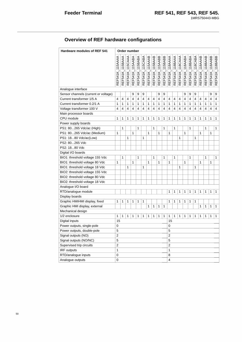
Feeder Terminal REF 541, REF 543, REF 545.1MRS750443-MBG
Overview of REF hardware configurations
Hardware modules of REF 541 Order number
REF
541K
_115
AAAA
REF
541K
_115
BAAA
REF
541K
_115
CAA
AR
EF54
1K_1
15AA
BAR
EF54
1K_1
15BA
BAR
EF54
1K_1
15C
ABA
REF
541K
_115
AAAB
REF
541K
_115
BAAB
REF
541K
_115
AABB
REF
541K
_115
BABB
REF
541K
_118
AAAA
REF
541K
_118
BAAA
REF
541K
_118
CAA
AR
EF54
1K_1
18AA
BAR
EF54
1K_1
18BA
BAR
EF54
1K_1
18C
ABA
REF
541K
_118
AAAB
REF
541K
_118
BAAB
REF
541K
_118
AABB
REF
541K
_118
BABB
Analogue interfaceSensor channels (current or voltage) 9 9 9 9 9 9 9 9 9 9Current transformer 1/5 A 4 4 4 4 4 4 4 4 4 4 4 4 4 4 4 4 4 4 4 4Current transformer 0.2/1 A 1 1 1 1 1 1 1 1 1 1 1 1 1 1 1 1 1 1 1 1Voltage transformer 100 V 4 4 4 4 4 4 4 4 4 4 4 4 4 4 4 4 4 4 4 4Main processor boardsCPU module 1 1 1 1 1 1 1 1 1 1 1 1 1 1 1 1 1 1 1 1Power supply boardsPS1: 80...265 Vdc/ac (High) 1 1 1 1 1 1 1 1PS1: 80...265 Vdc/ac (Medium) 1 1 1 1 1 1 1 1PS1: 18...80 Vdc/ac(Low) 1 1 1 1PS2: 80...265 VdcPS2: 18...80 VdcDigital I/O boardsBIO1: threshold voltage 155 Vdc 1 1 1 1 1 1 1 1BIO1: threshold voltage 80 Vdc 1 1 1 1 1 1 1 1BIO1: threshold voltage 18 Vdc 1 1 1 1BIO2: threshold voltage 155 VdcBIO2: threshold voltage 80 VdcBIO2: threshold voltage 18 VdcAnalogue I/O boardRTD/analogue module 1 1 1 1 1 1 1 1 1 1Display boardsGraphic HMIHMI display, fixed 1 1 1 1 1 1 1 1 1 1 1 1Graphic HMI display, external 1 1 1 1 1 1 1 1Mechanical design1/2 enclosure 1 1 1 1 1 1 1 1 1 1 1 1 1 1 1 1 1 1 1 1Digital inputs 15 15Power outputs, single-pole 0 0Power outputs, double-pole 5 5Signal outputs (NO) 2 2Signal outputs (NO/NC) 5 5Supervised trip circuits 2 2IRF outputs 1 1RTD/analogue inputs 0 8Analogue outputs 0 4
50
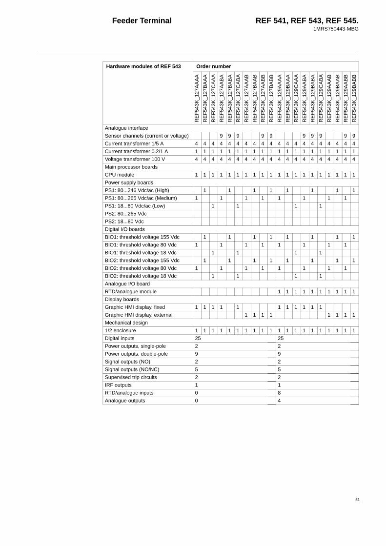
Feeder Terminal REF 541, REF 543, REF 545.1MRS750443-MBG
51
Hardware modules of REF 543 Order number
REF
543K
_127
AAAA
REF
543K
_127
BAAA
REF
543K
_127
CAA
AR
EF54
3K_1
27AA
BAR
EF54
3K_1
27BA
BAR
EF54
3K_1
27C
ABA
REF
543K
_127
AAAB
REF
543K
_127
BAAB
REF
543K
_127
AABB
REF
543K
_127
BABB
REF
543K
_129
AAAA
REF
543K
_129
BAAA
REF
543K
_129
CAA
AR
EF54
3K_1
29AA
BAR
EF54
3K_1
29BA
BAR
EF54
3K_1
29C
ABA
REF
543K
_129
AAAB
REF
543K
_129
BAAB
REF
543K
_129
AABB
REF
543K
_129
BABB
Analogue interfaceSensor channels (current or voltage) 9 9 9 9 9 9 9 9 9 9Current transformer 1/5 A 4 4 4 4 4 4 4 4 4 4 4 4 4 4 4 4 4 4 4 4Current transformer 0.2/1 A 1 1 1 1 1 1 1 1 1 1 1 1 1 1 1 1 1 1 1 1Voltage transformer 100 V 4 4 4 4 4 4 4 4 4 4 4 4 4 4 4 4 4 4 4 4Main processor boardsCPU module 1 1 1 1 1 1 1 1 1 1 1 1 1 1 1 1 1 1 1 1Power supply boardsPS1: 80...246 Vdc/ac (High) 1 1 1 1 1 1 1 1PS1: 80...265 Vdc/ac (Medium) 1 1 1 1 1 1 1 1PS1: 18...80 Vdc/ac (Low) 1 1 1 1PS2: 80...265 VdcPS2: 18...80 VdcDigital I/O boardsBIO1: threshold voltage 155 Vdc 1 1 1 1 1 1 1 1BIO1: threshold voltage 80 Vdc 1 1 1 1 1 1 1 1BIO1: threshold voltage 18 Vdc 1 1 1 1BIO2: threshold voltage 155 Vdc 1 1 1 1 1 1 1 1BIO2: threshold voltage 80 Vdc 1 1 1 1 1 1 1 1BIO2: threshold voltage 18 Vdc 1 1 1 1Analogue I/O boardRTD/analogue module 1 1 1 1 1 1 1 1 1 1Display boardsGraphic HMI display, fixed 1 1 1 1 1 1 1 1 1 1 1Graphic HMI display, external 1 1 1 1 1 1 1 1Mechanical design1/2 enclosure 1 1 1 1 1 1 1 1 1 1 1 1 1 1 1 1 1 1 1 1Digital inputs 25 25Power outputs, single-pole 2 2Power outputs, double-pole 9 9Signal outputs (NO) 2 2Signal outputs (NO/NC) 5 5Supervised trip circuits 2 2IRF outputs 1 1RTD/analogue inputs 0 8Analogue outputs 0 4
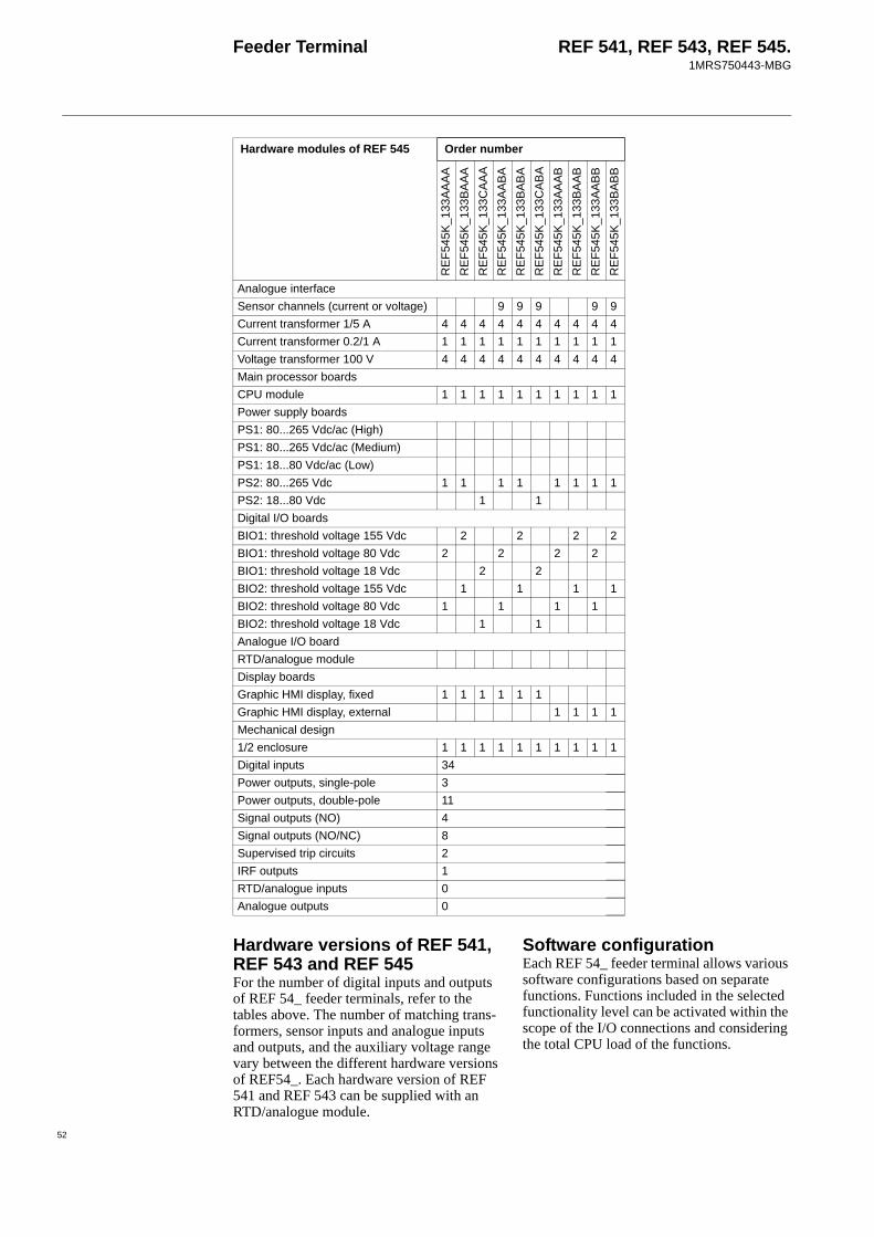
Feeder Terminal REF 541, REF 543, REF 545.1MRS750443-MBG
Hardware versions of REF 541, REF 543 and REF 545For the number of digital inputs and outputs of REF 54_ feeder terminals, refer to the tables above. The number of matching trans-formers, sensor inputs and analogue inputs and outputs, and the auxiliary voltage range vary between the different hardware versions of REF54_. Each hardware version of REF 541 and REF 543 can be supplied with an RTD/analogue module.
Software configurationEach REF 54_ feeder terminal allows various software configurations based on separate functions. Functions included in the selected functionality level can be activated within the scope of the I/O connections and considering the total CPU load of the functions.
Hardware modules of REF 545 Order number
REF
545K
_133
AAAA
REF
545K
_133
BAAA
REF
545K
_133
CAA
AR
EF54
5K_1
33AA
BAR
EF54
5K_1
33BA
BAR
EF54
5K_1
33C
ABA
REF
545K
_133
AAAB
REF
545K
_133
BAAB
REF
545K
_133
AABB
REF
545K
_133
BABB
Analogue interfaceSensor channels (current or voltage) 9 9 9 9 9Current transformer 1/5 A 4 4 4 4 4 4 4 4 4 4Current transformer 0.2/1 A 1 1 1 1 1 1 1 1 1 1Voltage transformer 100 V 4 4 4 4 4 4 4 4 4 4Main processor boardsCPU module 1 1 1 1 1 1 1 1 1 1Power supply boardsPS1: 80...265 Vdc/ac (High)PS1: 80...265 Vdc/ac (Medium)PS1: 18...80 Vdc/ac (Low)PS2: 80...265 Vdc 1 1 1 1 1 1 1 1PS2: 18...80 Vdc 1 1Digital I/O boardsBIO1: threshold voltage 155 Vdc 2 2 2 2BIO1: threshold voltage 80 Vdc 2 2 2 2BIO1: threshold voltage 18 Vdc 2 2BIO2: threshold voltage 155 Vdc 1 1 1 1BIO2: threshold voltage 80 Vdc 1 1 1 1BIO2: threshold voltage 18 Vdc 1 1Analogue I/O boardRTD/analogue moduleDisplay boardsGraphic HMI display, fixed 1 1 1 1 1 1Graphic HMI display, external 1 1 1 1Mechanical design1/2 enclosure 1 1 1 1 1 1 1 1 1 1Digital inputs 34Power outputs, single-pole 3Power outputs, double-pole 11Signal outputs (NO) 4Signal outputs (NO/NC) 8Supervised trip circuits 2IRF outputs 1RTD/analogue inputs 0Analogue outputs 0
52

Feeder Terminal REF 541, REF 543, REF 545.1MRS750443-MBG
53
Parts and assembly descriptionsTo achieve the best possible operation accu-racy, all parts of a REF 54_ product have been calibrated together. Thus, each product
forms a whole for which no separate spare parts can be supplied. In the event of mal-function, please consult your feeder terminal supplier.
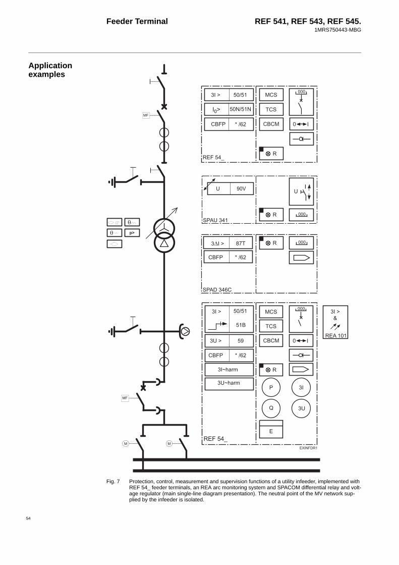
Feeder Terminal REF 541, REF 543, REF 545.1MRS750443-MBG
Application examples
Fig. 7 Protection, control, measurement and supervision functions of a utility infeeder, implemented with REF 54_ feeder terminals, an REA arc monitoring system and SPACOM differential relay and volt-age regulator (main single-line diagram presentation). The neutral point of the MV network sup-plied by the infeeder is isolated.
)F
#$/ :
#
#$#
+#
F 88
)F *+
#$/ :
#
9
/
#$#
+#
)
)
(8,
)F
)F
$
#$/ :
)FG
0
/)
/,)#
0
)H<52
)H<52
54
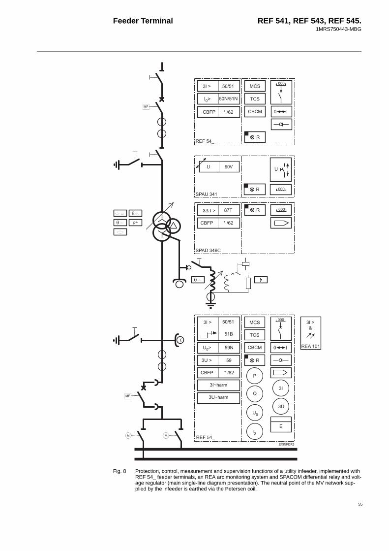
Feeder Terminal REF 541, REF 543, REF 545.1MRS750443-MBG
55
Fig. 8 Protection, control, measurement and supervision functions of a utility infeeder, implemented with REF 54_ feeder terminals, an REA arc monitoring system and SPACOM differential relay and volt-age regulator (main single-line diagram presentation). The neutral point of the MV network sup-plied by the infeeder is earthed via the Petersen coil.
(8,)
)FG
)F
#$/ :
#
#$#
+#
F 88
)F *+
#$/ :
#
9
/
#$#
+#
)
)
F 8
)F
#$/ :
)F
$
0
/)
/,)#
0
)H<52
)H<52

Feeder Terminal REF 541, REF 543, REF 545.1MRS750443-MBG
Fig. 9 An REF 54_ feeder terminal used for the protection, control, measurement and supervision func-tions of a utility feeder (main single-line diagram presentation). The neutral point of the supplying network is isolated. The scheme is also fully applicable in high-impedance earthed networks, where the neutral point is earthed via a high resistance or a Petersen coil.
)F
.F 8
)F
F *8
#$/ :
*
I
F
#
/
#$#
+#
)
)
(,
0
56

Feeder Terminal REF 541, REF 543, REF 545.1MRS750443-MBG
57
Fig. 10 REF 54_ feeder terminals used for the protection, control, measurement and supervision functions of a utility/industrial measurement cubicle (main single-line diagram presentation). The neutral point of the supplying network is isolated. The scheme is also fully applicable in high-impedance earthed networks, where the neutral point is earthed via a high resistance or a Petersen coil.
(
)F
I
#
+#
)
F 8
)I *
)F
I
#
+#
)
F 8
)I *
0 0

Feeder Terminal REF 541, REF 543, REF 545.1MRS750443-MBG
Fig. 11 Protection, control, measurement and supervision functions of a utility/industrial infeeder, imple-mented with REF 54_ feeder terminals, an REA arc monitoring system and SPACOM differential relay and voltage regulator (main single-line diagram presentation). The neutral point of the MV network supplied by the infeeder is earthed via a high resistance.
(8,
)FG
)F
#$/ :
#
#$#
+#
F 88
)F *+
#$/ :
#
/
#$#
+#
)
)
)F
#$/ :
)F
$
9
F 8
J8#
F 88
)F *
0
/)
/,)#
0
)H<52
)H<52
58

Feeder Terminal REF 541, REF 543, REF 545.1MRS750443-MBG
59
Fig. 12 An REF 54_ feeder terminal and an REA arc monitoring system (main single-line diagram presen-tation) used for the protection, control, measurement and supervision functions of a utility/industrial ring/meshed network cable feeder. The earthing of the supplying network can be of low or high impedance type.
)F *
F *8
)
J8#
I
)I *
)F
#$/ :
#
+#
#$#
9
/ )
)
3
(,)
)FG
0

Feeder Terminal REF 541, REF 543, REF 545.1MRS750443-MBG
Fig. 13 An REF 54_ feeder terminal used for the protection, control, measurement and supervision func-tions of a utility/light industrial cable feeder (main single line diagram presentation). The earthing of the supplying network can be of low or high impedance type.
)F
F
F 88
#
/
#$#
+#
)
)
)F
(,
#$/ :
0
60
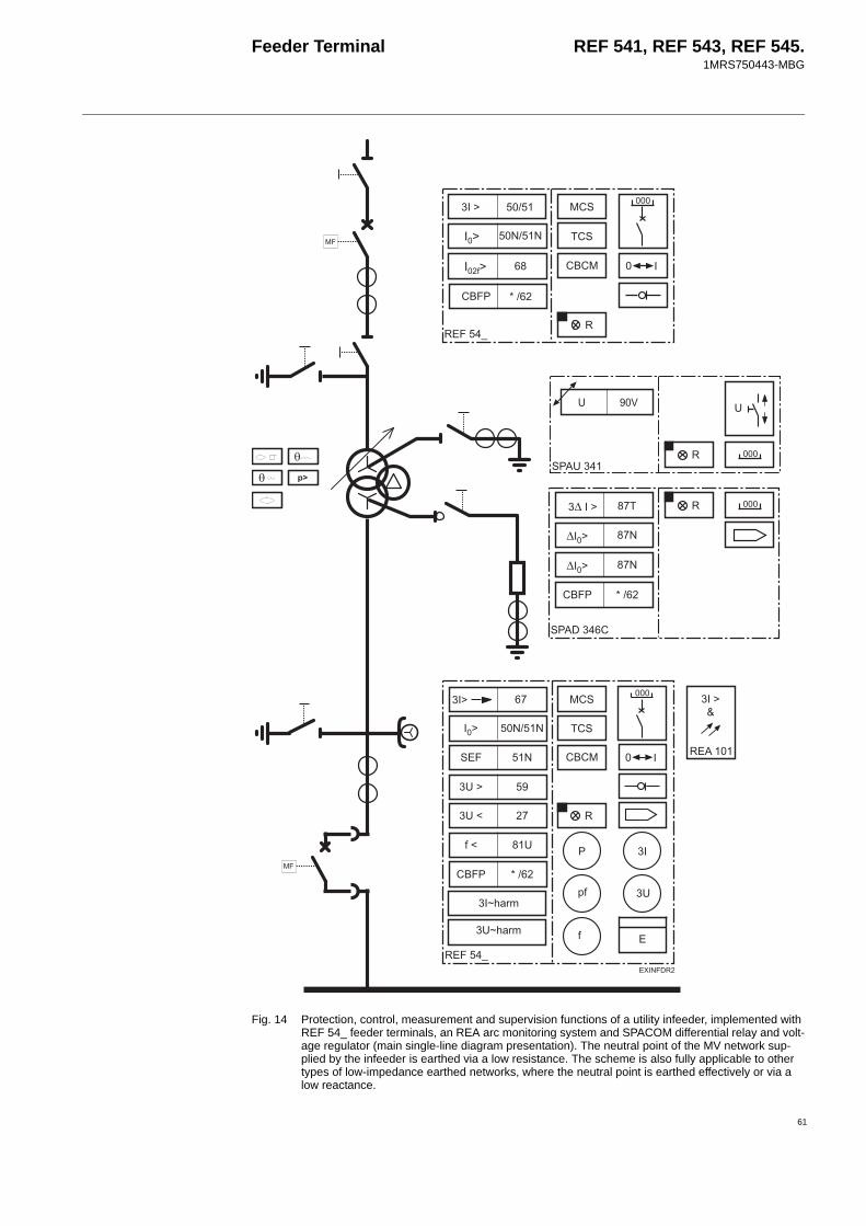
Feeder Terminal REF 541, REF 543, REF 545.1MRS750443-MBG
61
Fig. 14 Protection, control, measurement and supervision functions of a utility infeeder, implemented with REF 54_ feeder terminals, an REA arc monitoring system and SPACOM differential relay and volt-age regulator (main single-line diagram presentation). The neutral point of the MV network sup-plied by the infeeder is earthed via a low resistance. The scheme is also fully applicable to other types of low-impedance earthed networks, where the neutral point is earthed effectively or via a low reactance.
#
3
/
#$#
+#
)
)
(8,
)FG
)F *
F 88
8
)F
)I *
#$/ :
)F *+
F *8
F *8
#$/ :
)F
#$/ :
#
#$#
+#
F 88
F
0
/)
)H<52
)H<52
0
/,)#
I
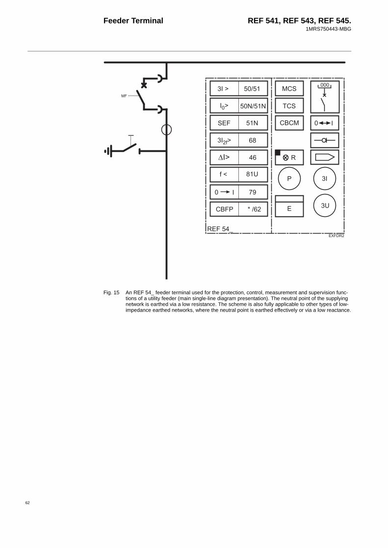
Feeder Terminal REF 541, REF 543, REF 545.1MRS750443-MBG
Fig. 15 An REF 54_ feeder terminal used for the protection, control, measurement and supervision func-tions of a utility feeder (main single-line diagram presentation). The neutral point of the supplying network is earthed via a low resistance. The scheme is also fully applicable to other types of low-impedance earthed networks, where the neutral point is earthed effectively or via a low reactance.
)F
)F
#$/ :
*
I
F
#
/
#$#
+#
)
)
F 88
8
(,
0
62
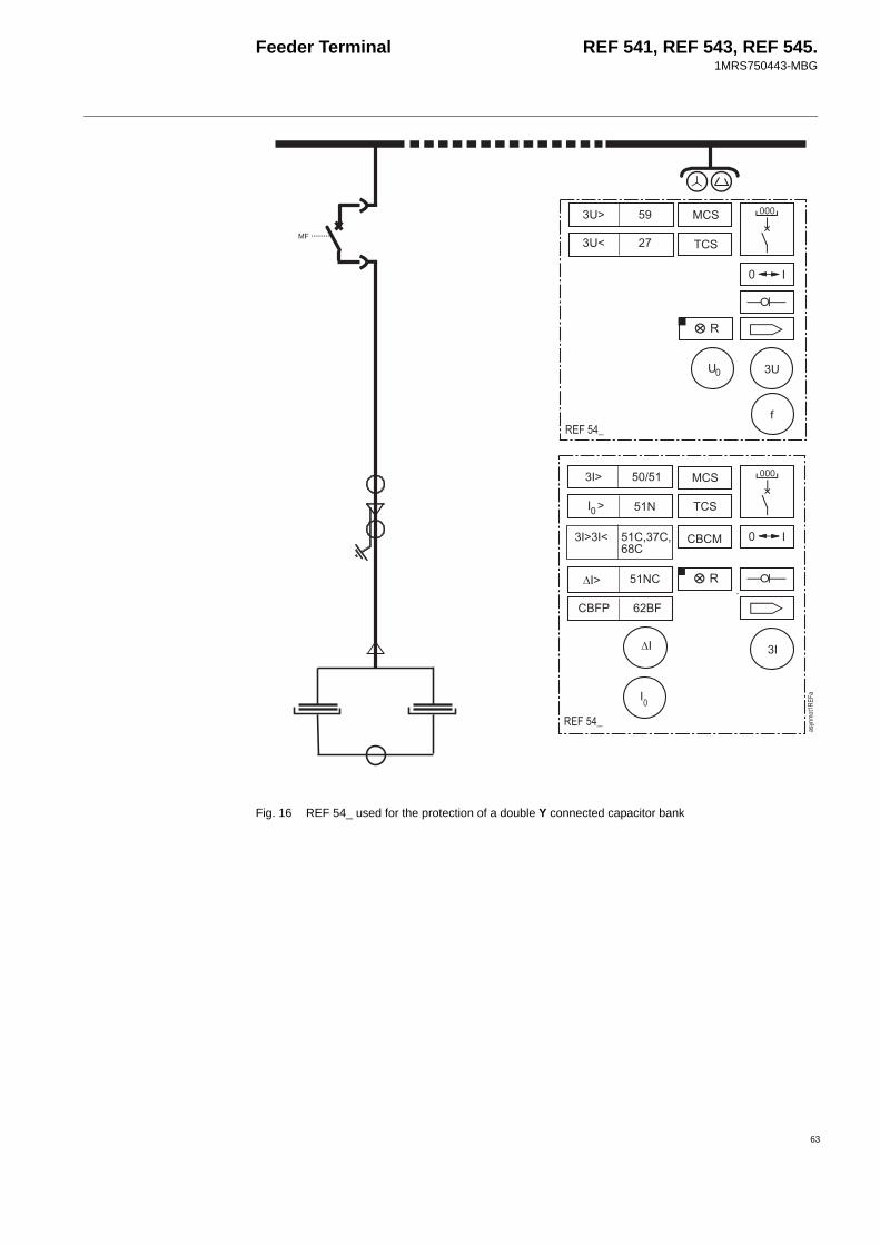
Feeder Terminal REF 541, REF 543, REF 545.1MRS750443-MBG
63
Fig. 16 REF 54_ used for the protection of a double Y connected capacitor bank
+#
#
*)I
)F
)
+#
#
#$#
)
#')*#' #
)F)I
#$/ $
)F
8F
F 8#

Feeder Terminal REF 541, REF 543, REF 545.1MRS750443-MBG
Fig. 17 REF 54_ used for the protection of a motor with direct-on-line starting
+#
#
*)I
)F
)
+#
#
#$#
/
3
)
''='I;
F
)
#$/ $
)F
8F
I
F
F
*
*
64
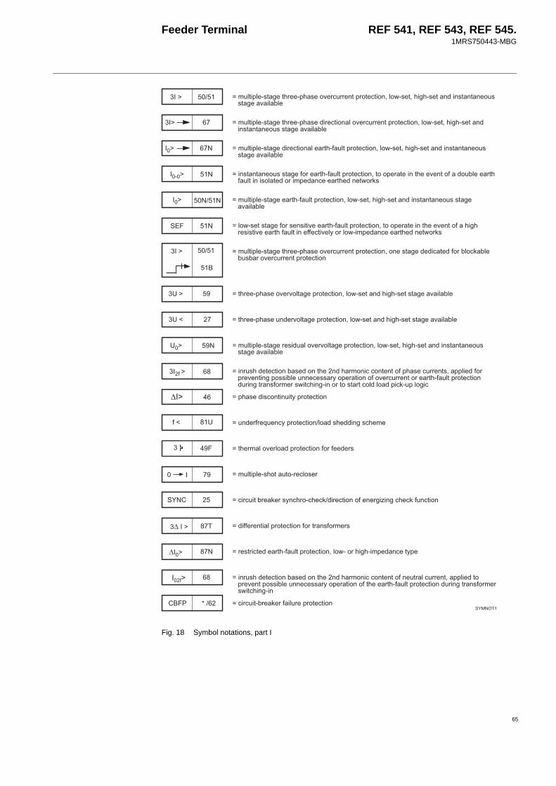
Feeder Terminal REF 541, REF 543, REF 545.1MRS750443-MBG
65
Fig. 18 Symbol notations, part I
)F
)F *
F *8
.F 8
F 88
8
)F
$
)F
)I *
F 8
)F
#$/ :
*
I
F
)
)F *+
F *8
F
24=6341.;=D1=<511.3<;1!?15551=35!=1=6!'4!>.;1='<6D<.;1=6;==1!;;=D1?64C41
24=6341.;=D1=<511.3<;1651=6!4!?15551=35!=1=6!'4!>.;1='<6D<.;1=6;==1!;;=D1?64C41
6;==1!;;=D1!515=<.4=35!=1=6!'=!!315=16=<11?1=!!C4115=<4=66;!4=1!56231115=<11=>!5";
24=6341.;=D1651=6!415=<.4=35!=1=6!'4!>.;1='<6D<.;1=6;==1!;;=D1?64C41
24=6341.;=D115=<.4=35!=1=6!'4!>.;1='<6D<.;1=6;==1!;;=D1?64C41
4!>.;1=;=D1!5;1;6=6?115=<.4=35!=1=6!'=!!315=16=<11?1=!<6D<51;6;=6?115=<4=611=6?14B!54!>.6231115=<11=>!5";
24=6341.;=D1=<511.3<;1!?15551=35!=1=6!'!1;=D116=1!5C4!"C41C;C5!?15551=35!=1=6!
=<511.3<;1!?15?!4=D135!=1=6!'4!>.;1=<6D<.;1=;=D1?64C41
=<511.3<;115?!4=D135!=1=6!'4!>.;1=<6D<.;1=;=D1?64C41
24=6341.;=D151;64!?15?!4=D135!=1=6!'4!>.;1='<6D<.;1=6;==1!;;=D1?64C41
65;<1=1=6!C;1!=<1<52!6!=1=!3<;1551=;'33461!5351?1=6D3!;;6C4111;;5B!315=6!!!?15551=!515=<.4=35!=1=6!56D=5;!5215;>6=<6D.6!5=!;=5=!44!36".34!D6
3<;16;!=66=B35!=1=6!
1551K1B35!=1=6!4!;<16D;<121
=<1524!?154!35!=1=6!!51115;
J8#
24=6341.;<!==!.514!;15
656=C51"15;B<5!.<1"651=6!!115D66D<1"=6!
6151=6435!=1=6!!5=5;!5215;
51;=56=115=<.4=35!=1=6!'4!>.!5<6D<.62311=B31
65;<1=1=6!C;1!=<1<52!6!=1=!1=54551='33461=!351?1=3!;;6C4111;;5B!315=6!!=<115=<.4=35!=1=6!56D=5;!5215;>6=<6D.6
656=.C51"15645135!=1=6!J8%+

Feeder Terminal REF 541, REF 543, REF 545.1MRS750443-MBG
Fig. 19 Symbol notations, part II
J8%+
8#F
)
=<511.3<;1;=5=.3;315?6;6!!52!=!5;
=<511.3<;1=<1524!?154!35!=1=6!!51?61;
551=C4135!=1=6!!5;<=36=!5C";
3<;1.;1K11?!4=D135!=1=6!';=D1;?64C41
=<511.3<;1!?154!35!=1=6!!5;<=36=!5C";
; = 'I ''
'I F'F
*'*'
)F')I #')*#' #
)FG
#
+#
#$#
9
/
)
)
3
535!=1=6!
21;56D656=;315?6;6!
=563656=;315?6;6!
656=.C51"15!6=6!2!6=!56D
=!2=6?!4=D151D4=6!
24?!4=D151D4=6!
=6?13!>1521;5121='66=6!;315?6;6!
51=6?13!>1521;5121='66=6!;315?6;6!
).3<;1551=21;5121='66=6!;315?6;6!
).3<;1?!4=D1!53<;1.=!.3<;1?!4=D121;5121='66=6!;315?6;6!
51K1B21;5121='66=6!;315?6;6!
3!>15=!521;5121='66=6!;315?6;6!
51;64551=21;5121='66=6!;315?6;6!
51;64?!4=D121;5121='66=6!;315?6;6!
66

Feeder Terminal REF 541, REF 543, REF 545.1MRS750443-MBG
67
Fig. 20 Symbol notations, part III
115DB!=15'!5>5!551?15;1=6?151=6?1115DB
6=6D'1?1=D115=6D?4151!56D=6!;
6;=5C151!515
6D6=4?4166=6!
#6;34B
4!4512!=1!=5!46=151
CB.!561=16=154!"6D4!D6
J8%+)
)H<52
)H<52
551=>?1!526;=!5=6!21;5121=
?!4=D1>?1!526;=!5=6!21;5121=
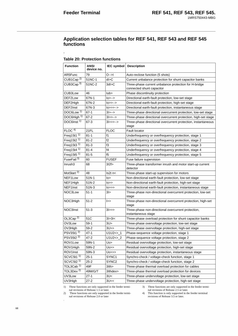
Feeder Terminal REF 541, REF 543, REF 545.1MRS750443-MBG
Application selection tables for REF 541, REF 543 and REF 545 functions.
1) These functions are only supported in the feeder termi-nal revisions of Release 1.5 or later.
2) These functions are only supported in the feeder termi-nal revisions of Release 2.0 or later
.
3) These functions are only supported in the feeder termi-nal revisions of Release 2.5 or later.
4) This function is only supported in the feeder terminal revisions of Release 3.5 or later.
Table 20: Protection functionsFunction ANSI
device no.IEC symbol Description
AR5Func 79 O-->I Auto-reclose function (5 shots)CUB1Cap 2) 51NC-1 dI>C Current unbalance protection for shunt capacitor banksCUB3Cap 3) 51NC-2 3dI>C Three-phase current unbalance protection for H-bridge
connected shunt capacitorCUB3Low 46 Iub> Phase discontinuity protectionDEF2Low 67N-1 Io>--> Directional earth-fault protection, low-set stageDEF2High 67N-2 Io>>--> Directional earth-fault protection, high-set stageDEF2Inst 67N-3 Io>>>--> Directional earth-fault protection, instantaneous stageDOC6Low 1) 67-1 3I>--> Three-phase directional overcurrent protection, low-set stageDOC6High 1) 67-2 3I>>--> Three-phase directional overcurrent protection, high-set stageDOC6Inst 1) 67-3 3I>>>--> Three-phase directional overcurrent protection, instantaneous
stageFLOC 4) 21FL FLOC Fault locatorFreq1St1 1) 81-1 f1 Underfrequency or overfrequency protection, stage 1Freq1St2 1) 81-2 f2 Underfrequency or overfrequency protection, stage 2Freq1St3 1) 81-3 f3 Underfrequency or overfrequency protection, stage 3Freq1St4 1) 81-4 f4 Underfrequency or overfrequency protection, stage 4Freq1St5 1) 81-5 f5 Underfrequency or overfrequency protection, stage 5FuseFail 3) 60 FUSEF Fuse failure supervisionInrush3 68 3I2f> Three-phase transformer inrush and motor start-up current
detectorMotStart 2) 48 Is2t n< Three-phase start-up supervision for motorsNEF1Low 51N-1 Io> Non-directional earth-fault protection, low-set stageNEF1High 51N-2 Io>> Non-directional earth-fault protection, high-set stageNEF1Inst 51N-3 Io>>> Non-directional earth-fault protection, instantaneous stageNOC3Low 51-1 3I> Three-phase non-directional overcurrent protection, low-set
stageNOC3High 51-2 I>> Three-phase non-directional overcurrent protection, high-set
stageNOC3Inst 51-3 3I>>> Three-phase non-directional overcurrent protection,
instantaneous stageOL3Cap 2) 51C 3I>3I< Three-phase overload protection for shunt capacitor banksOV3Low 59-1 3U> Three-phase overvoltage protection, low-set stageOV3High 59-2 3U>> Three-phase overvoltage protection, high-set stagePSV3St1 2) 47-1 U1U2<>_1 Phase-sequence voltage protection, stage 1PSV3St2 2) 47-2 U1U2<>_2 Phase-sequence voltage protection, stage 2ROV1Low 59N-1 Uo> Residual overvoltage protection, low-set stageROV1High 59N-2 Uo>> Residual overvoltage protection, high-set stageROV1Inst 59N-3 Uo>>> Residual overvoltage protection, instantaneous stageSCVCSt1 1) 25-1 SYNC1 Synchro-check / voltage-check function, stage 1SCVCSt2 1) 25-2 SYNC2 Synchro-check / voltage-check function, stage 2TOL3Cab 1) 49F 3Ith> Three-phase thermal overload protection for cablesTOL3Dev 2) 49M/G/T 3Ithdev> Three-phase thermal overload protection for devicesUV3Low 27-1 3U< Three-phase undervoltage protection, low-set stageUV3High 27-2 3U<< Three-phase undervoltage protection, high-set stage
68

Feeder Terminal REF 541, REF 543, REF 545.1MRS750443-MBG
69
1) These functions are only supported in the feeder termi-nal revisions of Release 1.5 or later.
2) These functions are only supported in the feeder termi-nal revisions of Release 2.0 or later
1) These functions are only supported in the feeder termi-nal revisions of Release 2.0 or later.
2) This function is only supported in the feeder terminal revisions of Release 3.5 or later
Table 21: Measurement functionsFunction ANSI device
no.IEC symbol Description
MEAI1 2) AI1 AI1 General measurement 1 / analog input on RTD/analog moduleMEAI2 2) AI2 AI2 General measurement 2 / analog input on RTD/analog moduleMEAI3 2) AI3 AI3 General measurement 3 / analog input on RTD/analog moduleMEAI4 2) AI4 AI4 General measurement 4 / analog input on RTD/analog moduleMEAI5 2) AI5 AI5 General measurement 5 / analog input on RTD/analog moduleMEAI6 2) AI6 AI6 General measurement 6 / analog input on RTD/analog moduleMEAI7 2) AI7 AI7 General measurement 7 / analog input on RTD/analog moduleMEAI8 2) AI8 AI8 General measurement 8 / analog input on RTD/analog moduleMEAO1 2) AO1 AO1 Analog output 1 on RTD/analog moduleMEAO2 2) AO1 AO1 Analog output 2 on RTD/analog moduleMEAO3 2) AO3 AO3 Analog output 3 on RTD/analog moduleMEAO4 2) AO4 AO4 Analog output 4 on RTD/analog moduleMECU1A Io Io Neutral current measurement, stage AMECU1B Io_B Io_B Neutral current measurement, stage BMECU3A 3I 3I Three-phase current measurement, stage AMECU3B 2) 3I_B 3I_B Three-phase current measurement, stage BMEDREC16 1)
DREC DREC Transient disturbance recorder
MEFR1 f f System frequency measurementMEPE7 PQE PQE Three-phase power and energy measurementMEVO1A Uo Uo Residual voltage measurement, stage AMEVO1B 2) Uo_B Uo_B Residual voltage measurement, stage BMEVO3A 3U 3U Three-phase voltage measurement, stage AMEVO3B 2) 3U_B 3U_B Three-phase voltage measurement, stage B
Table 22: Power quality functionsFunction ANSI device
no.IEC symbol Description
PQCU3H 1) PQ 3Inf PQ 3Inf Current waveform distortion measurementPQVO3H 1) PQ 3Unf PQ 3Unf Voltage waveform distortion measurementPQVO3Sd 2) PQ 3U<> PQ 3U<> Short duration voltage variations
Table 23: Control functionsFunction ANSI device
no.IEC symbol Description
CO3DC1 CO3DC1 I<->O 3DC1 Three-state disconnector (1) with indicationCO3DC2 CO3DC2 I<->O 3DC2 Three-state disconnector (2) with indicationCOCB1 COCB1 I<->O CB1 Circuit breaker 1 control with indicationCOCB2 COCB2 I<->O CB2 Circuit breaker 2 control with indicationCOCBDIR COCBDIR CBDIR Direct open for CBs via HMICODC1 CODC1 I<->O DC1 Disconnector 1 control with indicationCODC2 CODC2 I<->O DC2 Disconnector 2 control with indicationCODC3 CODC3 I<->O DC3 Disconnector 3 control with indicationCODC4 CODC4 I<->O DC4 Disconnector 4 control with indicationCODC5 CODC5 I<->O DC5 Disconnector 5 control with indicationCOIND1 COIND1 I<->O IND1 Switching device 1 indication

Feeder Terminal REF 541, REF 543, REF 545.1MRS750443-MBG
1) This function is only supported in the feeder terminal revisions of Release 2.0 or later
COIND2 COIND2 I<->O IND2 Switching device 2 indication COIND3 COIND3 I<->O IND3 Switching device 3 indicationCOIND4 COIND4 I<->O IND4 Switching device 4 indication COIND5 COIND5 I<->O IND5 Switching device 5 indicationCOIND6 COIND6 I<->O IND6 Switching device 6 indication COIND7 COIND7 I<->O IND7 Switching device 7 indication COIND8 COIND8 I<->O IND8 Switching device 8 indication COLOCAT COLOCAT I<->O POS Logic-controlled control position selectorCOPFC 1) 55 COPFC Power factor controllerCOSW1 COSW1 SW1 On/off switch 1 COSW2 COSW2 SW2 On/off switch 2COSW3 COSW3 SW3 On/off switch 3COSW4 COSW4 SW4 On/off switch 4MMIALAR1 ALARM1 ALARM1 Alarm channel 1, LED indicatorMMIALAR2 ALARM2 ALARM2 Alarm channel 2, LED indicatorMMIALAR3 ALARM3 ALARM3 Alarm channel 3, LED indicatorMMIALAR4 ALARM4 ALARM4 Alarm channel 4, LED indicatorMMIALAR5 ALARM5 ALARM5 Alarm channel 5, LED indicatorMMIALAR6 ALARM6 ALARM6 Alarm channel 6, LED indicatorMMIALAR7 ALARM7 ALARM7 Alarm channel 7, LED indicatorMMIALAR8 ALARM8 ALARM8 Alarm channel 8, LED indicatorMMIDATA1 MMIDATA1 MMIDATA1 MIMIC data monitoring point 1MMIDATA2 MMIDATA2 MMIDATA2 MIMIC data monitoring point 2MMIDATA3 MMIDATA3 MMIDATA3 MIMIC data monitoring point 3MMIDATA4 MMIDATA4 MMIDATA4 MIMIC data monitoring point 4MMIDATA5 MMIDATA5 MMIDATA5 MIMIC data monitoring point 5
Table 23: Control functionsFunction ANSI device
no.IEC symbol Description
Table 24: Condition monitoring functionsFunction ANSI device
no.IEC symbol Description
CMBWEAR1 CB wear1 CB wear1 Circuit-breaker electric wear 1CMBWEAR2 CB wear2 CB wear2 Circuit-breaker electric wear 2CMCU3 MCS 3I MCS 3I Supervision function of the energizing current input circuitCMGAS1 CMGAS1 GAS1 Gas pressure monitoringCMGAS3 1) CMGAS3 GAS3 Three-pole gas pressure monitoring CMSCHED CMSCHED SCHED Scheduled maintenanceCMSPRC1 CMSPRC1 SPRC1 Spring charging control 1CMTCS1 TCS1 TCS1 Trip circuit supervision 1CMTCS2 TCS2 TCS2 Trip circuit supervision 2CMTIME1 TIME1 TIME1 Operate time counter 1 for the operate time used (e.g. motors)CMTIME2 TIME2 TIME2 Operate time counter 2 for the operate time used (e.g. motors)CMTRAV1 CMTRAV1 TRAV1 Breaker travel time 1CMVO3 MCS 3U MCS 3U Supervision function of the energizing voltage input circuit
70

Feeder Terminal REF 541, REF 543, REF 545.1MRS750443-MBG
71
References Additional informationFeeder Terminal REF 54_ Technical ReferenceManual, General
1MRS750527-MUM
Technical Descriptions of Functions 1MRS750889-MCD (CD-ROM only)Installation Manual 1MR 750526-MUMOperator’s Manual 1MR 750500-MUMTechnical Reference Manual RER 103 1MRS750532-MUMTechnical Reference Manual RER 123 1MRS751143-MUMProtection & Control Terminals REF 54_, REM 54_, REC 523 Configuration Guideline
1MRS750745-MUM
Bus Connection Module RER 133 Technical Description
1MRS755163
Echelon, LON and LonTalk are registered trademarks of Echelon Corporation.All other product names or brands are trademarks, registered trademarks, or service marks of their respective owners.


ABB OyDistribution AutomationP.O. Box 699 FI-65101 Vaasa, FINLANDTel +358 10 22 11Fax +358 10 224 1094www.abb.com/substationautomation