reed switches catalog - hte · the hold value is the lower limit of the applied magnetic field at...
TRANSCRIPT

Ryazan Metal Ceramics Instrumentation Plant Joint Stock Company (RMCIP JSC)
REED SWITCHES CATALOG
RYAZAN 2003

Contents
Reed Switches
Ultra Miniature
MKA-07101
MKA-10109
Miniature
MKA-14103
MKA-16101
General Application
KAM-2
MKA-20101
High Power
MKA-50201
MKA-50202
Form C
KAM-3
MKC-27103
�

Ryazan Metal Ceramics Instrumentation Plant Joint Stock Company (RMCIP JSC)
has been specialized in producing reed switches from 1967. RMCIP JSC manufactures over
15 different types of dry reed switches designed for switching AC and DC signals at a
frequency of 10 kHz.
The manufacture at the factory is technically advanced with a high level of automated
control and specific requirements for cleanliness of the production area and quality of power
supply systems.
The factory is equipped with unique automated stamping machines, automated
equipment for cutting and fire-polishing glass, automated sealing equipment, plating station
for fine contact plating, automated measuring and test equipment.
A dry reed switch is an assembly containing ferromagnetic contact blades,
hermetically sealed in a glass tube that is filled with inert gas. The switch is operated by
an externally generated magnetic field, either from a coil or permanent magnet.
FEATURES
- Hermetically sealed glass tube ensures high performance in severe ambient
conditions (dust, gases, liquids);
- Long life (life expectancy to 15 years, life time to 108);
- Low contact resistance;
- Ambient operating temperature (-60°C to +155°С);
- Immunity to mechanical effects;
- Immunity to chemical attack;
- Low operating power, maintenance-free operation: by permanent magnet or
electromagnetic coil;
- High-response operation;
- Compact and light in weight;
- Low cost.
SCOPE OF APPLICATION
• Reed relays, for use in:
- Audio and video equipment
- Broadcast equipment
- Transport
- Domestic appliances
- Measuring and test equipment

- Military applications
- Aircraft
- Security systems
- Telephony
• Keyboards, for use in:
- Computers
- Military equipment
- Telephones
• Key switches, for use in:
- Audio and video equipment
- Domestic appliances
• Proximity switches, for use in:
- Conveyors
- Elevators
- Robotics
- Aircraft
• Security system applications, used in:
- Door sensors
- Window sensors
- Position sensors
• Miscellaneous applications, including:
- Flow sensors
- Level detectors
- Thermostats
- Domestic machines
- Toys
REED SWITCH CHARACTERISTICS PULL-IN AND DROP-OUT VALUES
The PULL-IN VALUE is the ampere-turn value at which normally-open contacts
close.
The DROP-OUT VALUE is the ampere-turn value at which normally-open contacts,
held closed by a magnetic field, will reopen as field strength is reduced.
The NON PULL-IN VALUE is the upper limit of the applied magnetic field at which
the dry reed switch shall not operate.

The HOLD VALUE is the lower limit of the applied magnetic field at which the closed
reed switch shall remain physically closed.
The SATURATE VALUE is the arbitrary defined value of the applied magnetic field
at which the dry reed switch is unaffected by further increase of the applied magnetic field
(see Fig.1).
Pull-In and Drop-Out values are measured in the measuring coils and are calculated as
the product of the current passing through the coils and the number of turns when the reeds
operate (release).
BOUNCE, RELEASE, OPERATE TIME
The OPERATE TIME is the time between the instant of application of a magnetic field
to a dry reed switch and the instant of the last physical closing of this switch. The operate time
includes the bounce time.
The RELEASE TIME is the time between the instant of removal of an applied
magnetic field to a dry reed switch and the instant of the last physical opening of this switch.
The release time includes the bounce time.
The BOUNCE TIME is the interval of time between the instant of the initial closing (or
opening) and the instant of final closing of the dry reed switch.
Time parameters are determined by measuring time intervals in accordance with
diagrams in Fig.2.
SATURATE VALUE
DROP-OUT VALUE
PULL-IN VALUE
Fig.1 Graphical representation of parameters
t(ms)
NON PULL-IN VALUE
HOLD VALUE
At
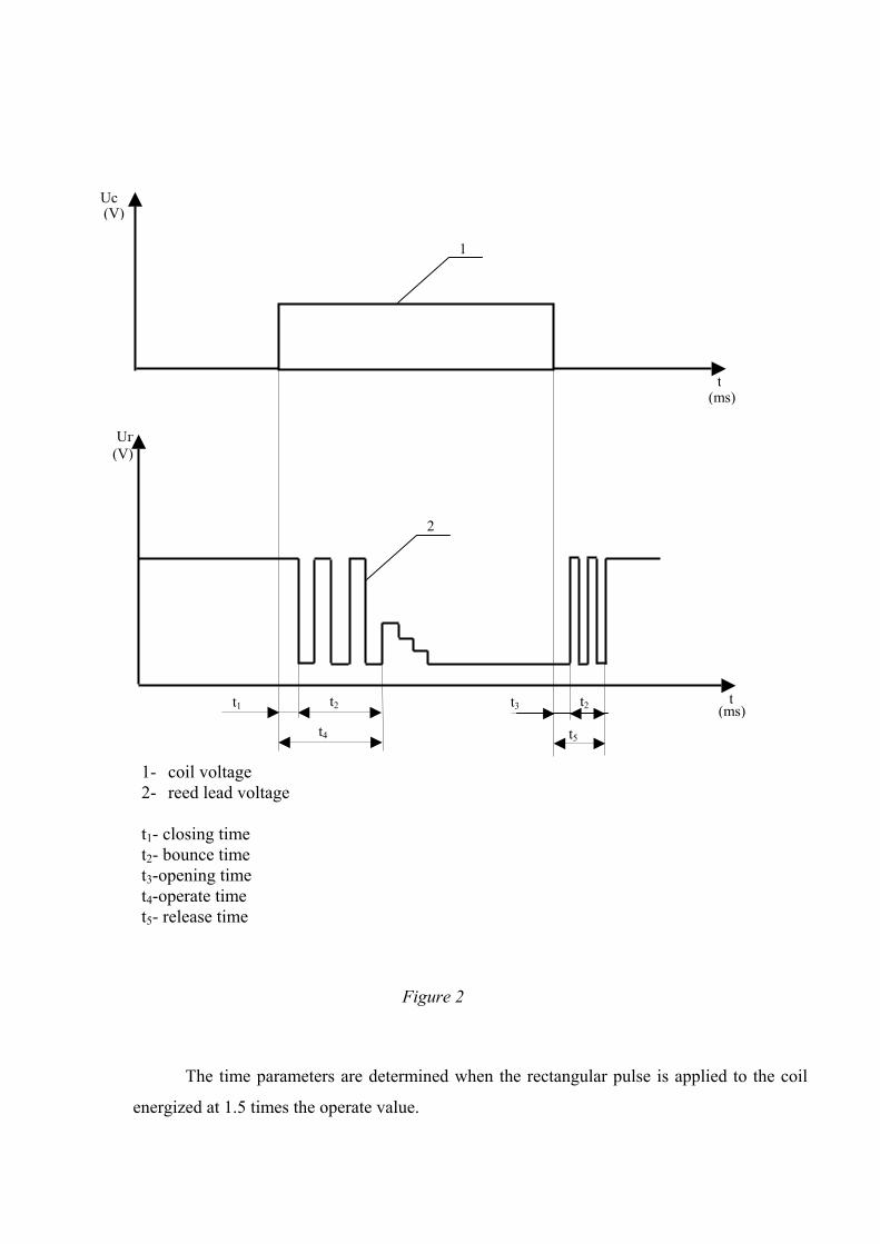
The time parameters are determined when the rectangular pulse is applied to the coil
energized at 1.5 times the operate value.
Uc
Uг
Figure 2
t
1
t1
2
t4
t
t3 t2 t2
t5
1- coil voltage 2- reed lead voltage t1- closing time t2- bounce time t3-opening time t4-operate time t5- release time
(V)
(ms)
(ms)
(V)

REED SWITCH RESISTANCE
The reed switch resistance includes the reed blade resistance and the contact resistance.
The contact resistance is measured by the four-point method (Kelvin Method) when the
contacts are closed. The measuring instrument should be connected to the reed switch at a
distance not more than 8 mm from the glass tube. Measuring conditions 6V-10mA or 20mV-
10mA. The coil is energized at 1.5 times the operate value.
BREAKDOWN VOLTAGE
The BREAKDOWN VOLTAGE is the maximum voltage (AC, DC) the switch can
withstand without leakage between open contacts.
The test voltage is applied to the open reed switch for not less than 1min. or for not
less than 1 sec. when it is increased at 1.1 times. The breakdown current is 1-20 mA.
INSULATION RESISTANCE
The INSULATION RESISTANCE – is the resistance of the reed switch with open
contacts.
It is measured at 100V for not less than 1 min.
REED SWITCH CAPACITANCE
The CAPACITANCE is the capacitance between overlapping reeds in the contact area
in their open position.
The capacitance is measured at a frequency of 1000 Hz and at a voltage of not more
than 50V.
LIFE EXPECTANCY
The life of a dry reed switch is influenced by:
- The load and the load circuit parameters
- Switching frequency
- Ambient temperature
- The applied magnetic field

METHODS OF OPERATING REED SWITCHES
Operation using a coil
The coil must produce the magneto-motive force required to operate the switch and
hold it closed. The coil is energized at 1.5 times the operate value.
Figures 3-5 illustrate various methods of operating the switch using a coil Figure 3. A dry reed switch mounted within a coil Figure 4. A dry reed switch mounted outside a coil
Operation using permanent magnets
Various combinations of magnet and the switch positions effect operation. The main methods of operating are illustrated in figures 6-12.
Solid lines indicate Pull-In, section lines indicate Drop-Out.
SN
SN
S N
SN
Figure 5. A dry-reed switch biased by a permanent magnet and operated by a coil

Х
S
-Х Х
Y
0
N
Y
0 -Х Х
off 2 on 2
off 1 on 1 off 3 on 3
Figure 6
Х
S
-Х Х
0
N
Y
Z
Z
0 -Х Х
Y
off 2 off 1
on 1
off 3
on 3
-Z -Z -Z
Z Z ZYY
on 2
Figure 7
on
off
S N
Yoff 2
on 2 off 1 on 1
off3 on 3
0
YY
0
-Х Х Figure 8

on
off
S
N
Х
on 2 off 1 on 1
0
-Х Х
Y
Х
Y 0
Y
off 2
Figure 9
Y
S
N
-Х Х
Z
0
Z
Х on 2
off1
on1
0
Yoff 2
Z Z YY
Figure 10 -Z-Z
S
N
Y
off 2 on 2 off1
on 1
-Х Х
0
Figure 11

Х
-Х Х
0
Y
S N
α
-Х
-Х
Х
Х0 0 0
on2
on3
on1
off3
off2
off1
off3
180˚
off2
180˚
off1
180˚
on
1
on2
on3
Figure 12
αα α

OPERATION INSTRUCTIONS
While the reed switch is in use avoid any mechanical stresses with associated hazard of
broken glass and leads.
Care must be taken to prevent from any affect of the external magnetic field.
Reed switches should be operated within characteristics as stated.
The current through contacts must not exceed the maximum switching current, the
supply voltage must not exceed the maximum switching voltage, the load voltage must not
exceed the maximum contact rating.
Stray inductance and capacitance should be taken into account. To reduce their
influence the load should be located within the close proximity of the reed switch.
In case of no load, life time is 108. As the load increases the life time reduces. It is
caused by erosion processes taking place on contact surfaces when reeds close/open. To
enhance reed switch reliability protective circuits are recommended (Figs.13-16).
-When using reed switches for resistive loads the contact-protection is carried out with an RC-
network (Figure 13).
To prevent arc striking the following condition must be fulfilled:
Where, Vr – reed blade voltage when the contacts are opened, V;
V – supply voltage, V;
R – resistance value, Ohm;
Rl – load resistance, Ohm;
Load resistance is calculated by:
V+ –
С R Rl
Figure 13
10≤+
=l
r RRRVV
lswitch IIVR
−≥
.max.

Where,
Iswitch.max.– maximum switching current, А;
Il – load current, А;
The capacitance value is expressed by: С=(0,05÷1,0)·Iswitch
Where,
С – capacitance value, µF
Iswitch – switching current, А;
When using reed switches for inductive loads the contact protection is carried out with
a diode (Figure 14).
The rated current of the diode must not exceed the switching current.
The reverse rated voltage must not exceed the supply voltage V.
-When using reed switches for capacitive loads the contact protection is carried out
with a resistor (Figure 15).
+ –
Rl
Figure 14
LlV
lRVI =
Rl
Figure 15
Сl
R
V + –

The resistance value is calculated by:
R≥V/Iswitch.max.
Or
R>V2/Pmax.
Where,
Imax. – maximum switching current
Pmax. – maximum contact rating.
- When using reed switches for lamp loads the contact protection is carried out with a
resistor (Figure 16).
To reduce the high inrush current to Iswitch.max. value the following condition must be
fulfilled:
R+Rcl = V/Iswitch.max.
Where,
Rcl.-the cold lamp resistance that is 8-14 times less than the hot lamp resistance
R – the resistance value
l
Figure 16
R
V + –

MOUNTING INSTRUCTIONS
Reed switches can be used both for plug-in and PCB mounting.
When mounting extreme caution should be exercised not to exert any undue stress that
can result in damage or leakage of the reed switch. It is recommended to provide an adequate
spacing between the reed switches.
When it is necessary to connect more than one wire to the leads the second and all next
wires must be soldered (or welded) to the earlier soldered wire but not to the lead. The wire
section must be equal to the reed lead section.
When welding or soldering reed switches deformation should be minimal. The output
power of the soldering iron must not exceed 100 W. The time of continuous heating of the
leads should not exceed 3 sec.
In case of re-soldering time is needed for the switch to be cooled after the earlier
heating. Soldering is permitted at a temperature of the soldering iron of not more than 2600C.
Recommended distance between the glass end and a bending point should be 3mm
min. When bending a reed switch lead but not glass body should be firmly hold to avoid a
broken glass. Re-bending is not acceptable. Figure 17 shows cutting techniques.
Note: bending and cutting can change pull-in and drop-out characteristics.
Figure 17

QUALITY ASSURANCE AND QUALITY CONTROL AT PRE-SERIES PHASE
(DESIGN AND R&D) AND AT SERIES A TÜV approved quality system of the factory has been developed and is currently operating
to meet ISO9001 quality requirements.
It is the factory managerial consideration that the factory quality system is the basics of
reliable and honest relationship between customers and suppliers. Following is the basis to
achieve a required quality level:
- State-of-art process application;
- Each employee’s interest in improving product quality;
- Continuous quality improvement;
- On-going personnel education.
Reed switches are UL recognized with File # E229065 for NRNT2 Switches, Industrial
Control-Component.
Figure 18 shows quality control and inspection flow chart for reed switch production cycle.

Cleaning
Deburring and Polishing
Glass Tube Cleaning
Plating
Leakage Test
Incoming Inspection
Glass Tube Annealing
- Operator Inspection
- Quality Control
Glass Tube Inspection and Packing
Glass Fire-Polishing
Clean Room
- Materials Supplied
Figure 18. Quality control and inspection flow chart for the production cycle
Visual Inspection
Sorting and Packing
Stamping
Glass Tube
Packing
Glass Cut
Testing for Electrical Parameters
Incoming Inspection
Wire
Sealing
Blade Inspection and Packing

Specifications for MKA-07101
Contact form 1AContact material RuMaximum switching power , W 1Maximum switching voltage , V 24Maximum switching current, A 0,1Pull in , AT 7-35Drop out, AT min. 4Contact resistance, Ohm max. 0,2Breakdown voltage, V dc min. 150Insulation resistance, Ohm min. 1·109
Operate time, ms max. 0,3Release time, ms max. 0,1Capacitance, pF max. 0,4Resonant frequency, Hz min. 12000Operate temperature range, º C -60 +125High humidity at T=35º C, % max. 98Operation frequency, Hz max. 400Test coil:Number of turnsResistance, Ohm
5000580
UL file# E229065
�
Coil energized 1.5 times each stated max. operate value.Customized switches are available upon request:
- with close PI values;- with cut, bent, flat leads;
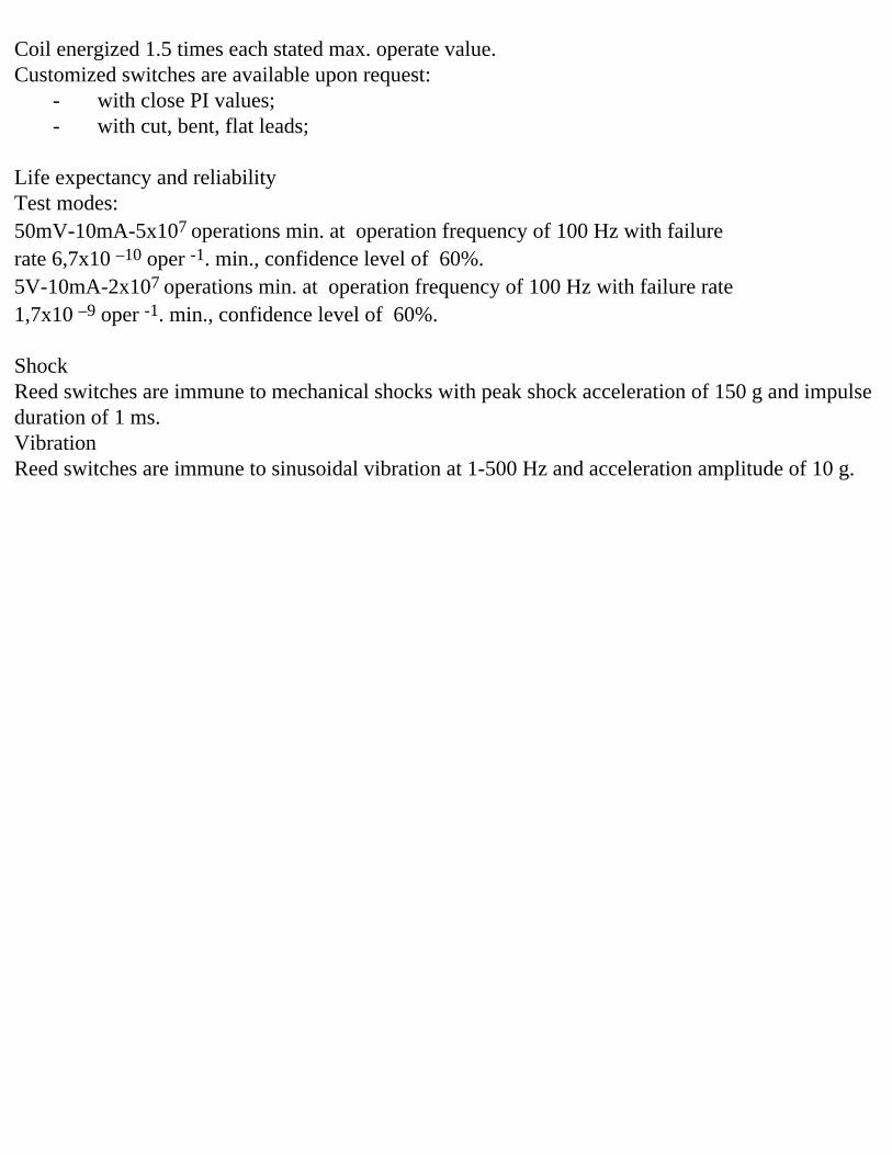
Life expectancy and reliabilityTest modes:50mV-10mA-5x10⁷ operations min. at operation frequency of 100 Hz with failure rate 6,7x10 –10 oper -1. min., confidence level of 60%.5V-10mA-2x10⁷ operations min. at operation frequency of 100 Hz with failure rate 1,7x10 –9 oper -1. min., confidence level of 60%. ShockReed switches are immune to mechanical shocks with peak shock acceleration of 150 g and impulse duration of 1 ms.VibrationReed switches are immune to sinusoidal vibration at 1-500 Hz and acceleration amplitude of 10 g.
�

0.1
1
510
203040
20 4 6 8
50607080
90
95
99
99.9
(5) Lead tensile strength
0.1
1
510
203040
12020
0
10
20
30
40
50
30 40 50 ÀT
AT
140 160 200
50607080
90
95
99
99.9
0.1
1
510
20304050607080
90
95
99
99.9
(1) Drop-out vs. Pull-in.
(3) Breakdown voltage
(2) Contact resistance
(4) Insulation resistance
0
200
300
400
30 40 50
10 10 10 10 109 10 11 12 13
ELECTRICAL CHARACTERISTICS
10
10
20
180
MKA-07101
100
AT
DC:V
DC100V
Pull-in.
Pull-in.
Contact resistance
Insulation resistance
Kg
Cum
ula
tive
frequency
perc
ent
Cu
mu
lative
fre
qu
en
cy
pe
rce
nt
Bre
akdow
nvolt
age
Dro
p-o
ut
�m
�
MECHANICAL CHARACTERISTICS
Breaking load

Specifications for MKA-10109
Contact form 1AContact material RuMaximum switching power , W 10Maximum switching voltage , V 100Maximum switching current, A 0,5Pull in , AT 10-35Drop out, AT min. 4Contact resistance, Ohm max. 0,1Breakdown voltage, V dc min. 150Insulation resistance, Ohm min. 1·109
Operate time, ms max. 0,5Release time, ms max. 0,3Capacitance, pF max. 0,5Resonant frequency, Hz min. 5000Operate temperature range, º C -60 +125High humidity at T=35º C, % max. 98Operation frequency, Hz. max. 400Test coil:Number of turnsResistance, Ohm
5000580
UL file# E229065
Customized switches are available upon request:
�

- with close PI values;- with cut, bent, flat leads;
Life expectancy and reliabilityTest modes:24V-250mA-1x10⁵ operations min. at operation frequency of 50 Hz with failure rate 3,3x10 –7 oper -1. min., confidence level of 60%.5V-10mA-5x10⁶ operations min. at operation frequency of 100 Hz with failure rate 6,7x10 –9 oper -1. min., confidence level of 60%.50mV-5•A-5x10⁶ operations min. at of 100 Hz with failure rate 6,7x10 –9 oper -1. min., confidence level of 60%.These data are valid for a coil energized at 1.5 times stated max. operate value.ShockReed switches are immune to mechanical shocks with peak shock acceleration of 150 g and impulse duration of 1 ms.VibrationReed switches are immune to sinusoidal vibration at 1-2000 Hz and acceleration amplitude of 10 g.

0.1
1
510
203040
100
10
20
30
40
50
20 30 40 50 AT
AT
60 80 100 �
50607080
90
95
99
99.9
Contact resistancePull-in
(1) Drop-out vs. Pull-in(2) Contact resistance
Cum
ula
tive
frequency
perc
ent
Dro
p-o
ut
120
0.1
1
510
20304050607080
90
95
99
99.9
(4) Insulation resistance
10 10 10 1010 11 12 13 �
(DC 100V)
Insulation resistance
Cu
mu
lative
fre
qu
en
cy
pe
rce
nt
109
(3) Breakdown voltage
100
100
200
300
400
500
20 30 40 50 AT
DC : V
Pull-in
Bre
akdow
nvoltage
ELECTRICAL CHARACTERISTICS
40
MKA-10109
0.1
1
510
203040
20 4 6 8 kg
50607080
90
95
99
99.9
Breaking load
(5) Lead tensile strength
Cum
ula
tive
frequency
perc
ent
MECHANICAL CHARACTERISTICS

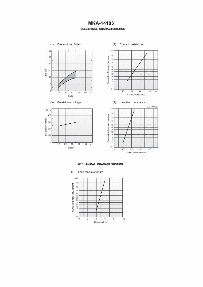
Specifications for MKA-14103
Contact form 1AContact material RuMaximum switching power , W 10Maximum switching voltage , V 100Maximum switching current, A 0,5Pull in , AT 10-35Drop out, AT min. 5Contact resistance, Ohm max. 0,1Breakdown voltage, V dc min. 220 AT≤25
250 AT>25Insulation resistance, Ohm min. 1·1010
Operate time, ms max. 1,0Release time, ms max. 0,4Capacitance, pF max. 0,7Resonant frequency, Hz min. 4000Operate temperature range, º C -60 +155High humidity at T=35º C, % max. 98Operation frequency, Hz max. 100Test coil:Number of turnsResistance, Ohm
5000870
UL file# E229065

Customized switches are available upon request:
- with close PI values;- with cut, bent, flat leads;
Life expectancy and reliabilityTest modes:5V-10mA-1x10⁸ operations min. at operation frequency of 100 Hz with failure rate 3,3x10 –10 oper -1. min., confidence level of 60%.24V-400mA-1x10⁵ operations min. at operation frequency of 50 Hz with failure rate 3,3x10 –7 oper -1. min., confidence level of 60%.These data are valid for a coil energized at 1.5 times stated max. operate value.ShockReed switches are immune to mechanical shocks with peak shock acceleration of 150 g and impulse duration of 1 ms.VibrationReed switches are immune to sinusoidal vibration at 1-2000 Hz and acceleration amplitude of 20 g.
0.1
1
510
203040
20 4 6 8 kg
50607080
90
95
99
99.9
Breaking load
(5) Lead tensile strength
Cum
ula
tive
frequency
perc
ent
MECHANICAL CHARACTERISTICS
0.1
1
510
203040
4020
0
10
20
30
40
50
30 40 50 AT
AT
60 80 100 m �
50607080
90
95
99
99.9
0.1
1
510
20304050607080
90
95
99
99.9
Contact resistancePull-in
(1) Drop-out vs. Pull-in
(3) Breakdown voltage
(2) Contact resistance
(4) Insulation resistance
Cum
ula
tive
frequency
perc
ent
Dro
p-o
ut
0
200
300
400
100
30 40 50 AT
DC : V
Pull-in
Bre
akdow
nvoltage
10 10 10 10 109 10 11 12 13 �
(DC 100V)
Insulation resistance
Cum
ula
tive
frequency
perc
ent
ELECTRICAL CHARACTERISTICS
10
10
20
MKA-14103

Specifications for MKA-16101
Contact form 1AContact material RuMaximum switching power , W 5 (lamp load)
10 (resistive load)Maximum switching voltage , V 100Maximum switching current, A 0,5Pull in , AT 10-35Drop out, AT min. 5Contact resistance, Ohm max. 0,1Breakdown voltage, V dc min. 220Insulation resistance, Ohm min. 1·109
Operate time, ms max. 0,6Release time, ms max. 0,4Capacitance, pF max. 0,3Resonant frequency, Hz min. 3000Operate temperature range, º C -60 +125High humidity at T=35º C, % max. 98Operation frequency, Hz max. 400Test coil:Number of turnsResistance, Ohm
5000620
UL file# E229065
Customized switches are available upon request:- with close PI values;- with cut, bent, flat leads;
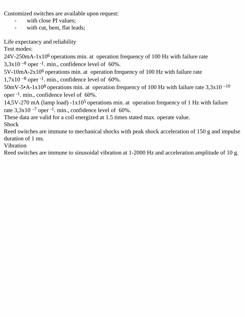
Life expectancy and reliabilityTest modes:24V-250mA-1x10⁶ operations min. at operation frequency of 100 Hz with failure rate 3,3x10 –8 oper -1. min., confidence level of 60%.5V-10mA-2x10⁶ operations min. at operation frequency of 100 Hz with failure rate 1,7x10 –8 oper -1. min., confidence level of 60%.50mV-5•A-1x10⁸ operations min. at operation frequency of 100 Hz with failure rate 3,3x10 –10 oper -1. min., confidence level of 60%.14,5V-270 mA (lamp load) -1x10⁵ operations min. at operation frequency of 1 Hz with failure rate 3,3x10 –7 oper -1. min., confidence level of 60%.These data are valid for a coil energized at 1.5 times stated max. operate value.ShockReed switches are immune to mechanical shocks with peak shock acceleration of 150 g and impulse duration of 1 ms.VibrationReed switches are immune to sinusoidal vibration at 1-2000 Hz and acceleration amplitude of 10 g.
�

0.1
1
510
203040
4020
0
10
20
30
40
50
30 40 50 AT
AT
60 80 100 m �
50607080
90
95
99
99.9
0.1
1
510
20304050607080
90
95
99
99.9
Contact resistancePull-in
(1) Drop-out vs. Pull-in
(3) Breakdown voltage
(2) Contact resistance
(4) Insulation resistance
Cum
ula
tive
frequency
perc
ent
Dro
p-o
ut
0
200
300
400
100
30 40 50 AT
DC : V
Pull-in
Bre
akdow
nvoltage
10 10 10 10 109 10 11 12 13
�
(DC 100V)
Insulation resistance
Cum
ula
tive
frequency
perc
ent
0.1
1
510
203040
20 4 6 8 kg
50607080
90
95
99
99.9
Breaking load
(5) Lead tensile strength
Cum
ula
tive
frequency
perc
ent
MECHANICAL CHARACTERISTICS
ELECTRICAL CHARACTERISTICS
10
10
20
MKA-16101

Specifications for KAM-2
Contact form 1AContact material RuMaximum switching power , W 10Maximum switching voltage , V 180Maximum switching current, A 0,5Pull in , AT 15-64Drop out, AT min. 5Contact resistance, Ohm max. 0,15Breakdown voltage, V dc min. 250Insulation resistance, Ohm min. 1·109
Operate time, ms max. 1,0Release time, ms max. 0,5Capacitance, pF max. 0,4Resonant frequency, Hz min. 2400Operate temperature range, º C -60 +125High humidity at T=35º C, % max. 98Operation frequency, Hz max. 100Test coil:Number of turnsResistance, Ohm
5000550
UL file# E229065
Customized switches are available upon request:- with close PI values;- with cut, bent, flat leads;
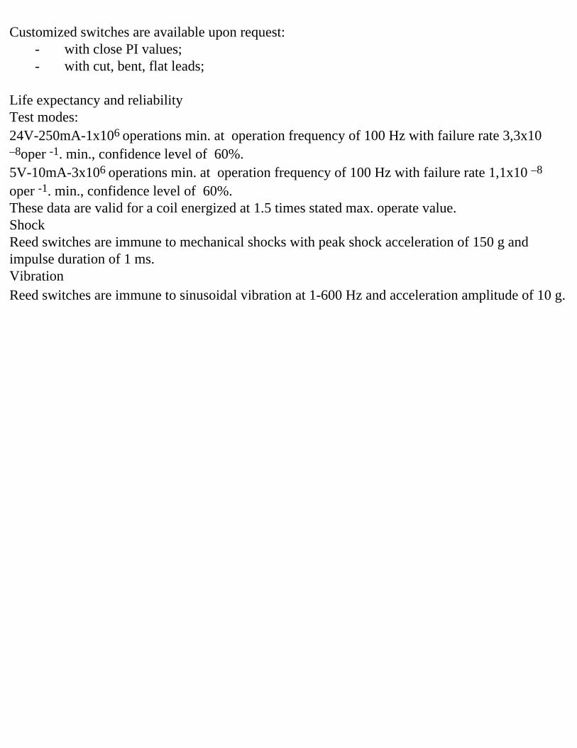
Life expectancy and reliabilityTest modes:24V-250mA-1x10⁶ operations min. at operation frequency of 100 Hz with failure rate 3,3x10 –8oper -1. min., confidence level of 60%.5V-10mA-3x10⁶ operations min. at operation frequency of 100 Hz with failure rate 1,1x10 –8 oper -1. min., confidence level of 60%.These data are valid for a coil energized at 1.5 times stated max. operate value.ShockReed switches are immune to mechanical shocks with peak shock acceleration of 150 g and impulse duration of 1 ms.VibrationReed switches are immune to sinusoidal vibration at 1-600 Hz and acceleration amplitude of 10 g.

0.1
1
510
203040
5040
0
10
20
30
40
50
60 80 100 AT
AT
100 150 200 m �
50607080
90
95
99
99.9
0.1
1
510
20304050607080
90
95
99
99.9
Contact resistancePull-in
(1) Drop-out vs. Pull-in
(3) Breakdown voltage
(2) Contact resistance
(4) Insulation resistance
Cum
ula
tive
frequency
perc
ent
Dro
p-o
ut
0
200
300
400
100
AT
DC : V
Pull-in
Bre
akdow
nvoltage
10 10 10 1010 11 12 13 �
(DC 100V)
Insulation resistance
Cum
ula
tive
frequency
perc
ent
0.1
1
510
203040
20 4 6 8 kg
50607080
90
95
99
99.9
Breaking load
(5) Lead tensile strength
Cum
ula
tive
frequency
perc
ent
MECHANICAL CHARACTERISTICS
ELECTRICAL CHARACTERISTICS
20
20
KAM-2
40 60 80 100
109

Specifications for MKA-20101
Contact form 1AContact material RuMaximum switching power , W 10Maximum switching voltage , V 180Maximum switching current, A 0,5Pull in , AT 10-40Drop out, AT min. 4Contact resistance, Ohm max. 0,15Breakdown voltage, V dc min. 220 (AT≤20)
280 (AT>20)Insulation resistance, Ohm min. 1·109
Operate time ,ms max. 1,0Release time, ms max. 0,3Capacitance, pF max. 0,4Resonant frequency, Hz min. 2600Operate temperature range, º C -60 +125High humidity at T=35º C, % max. 98Operation frequency, Hz max. 100Test coil:Number of turnsResistance, Ohm
5000550
UL file # E229065
�

Customized switches are available upon request:- with close PI values;- with cut, bent, flat leads;
Life expectancy and reliabilityTest modes:24V-250mA-1x10⁶ operations min. at operation frequency of 100 Hz with failure rate 3,3x10 –8 oper -1. min., confidence level of 60%.5V-10mA-1x10⁷ operations min. at operation frequency of 100 Hz with failure rate 3,3x10 –9 oper -1. min., confidence level of 60%.These data are valid for a coil energized at 1.5 times stated max. operate value.ShockReed switches are immune to mechanical shocks with peak shock acceleration of 150 g and impulse duration of 1 ms.VibrationReed switches are immune to sinusoidal vibration at 1-2000 Hz and acceleration amplitude of 20 g.

0.1
1
510
203040
5010
0
5
10
15
20
25
20 30 40 50 AT
AT
100 150 200 m �
50607080
90
95
99
99.9
0.1
1
510
20304050607080
90
95
99
99.9
Contact resistancePull-in
(1) Drop-out vs. Pull-in
(3) Breakdown voltage
(2) Contact resistance
(4) Insulation resistance
Cum
ula
tive
frequency
perc
ent
Dro
p-o
ut
100
100
200
300
400
20 30 40 50 AT
DC : V
Pull-in
Bre
akdow
nvoltage
�
(DC 100V)C
um
ula
tive
frequency
perc
ent
0.1
1
510
203040
20 4 6 8 kg
50607080
90
95
99
99.9
Breaking load
(5) Lead tensile strength
Cum
ula
tive
frequency
perc
ent
MECHANICAL CHARACTERISTICS
ELECTRICAL CHARACTERISTICS
500
MKA-20101
10 10 10 1010 11 12 13
Insulation resistance
109
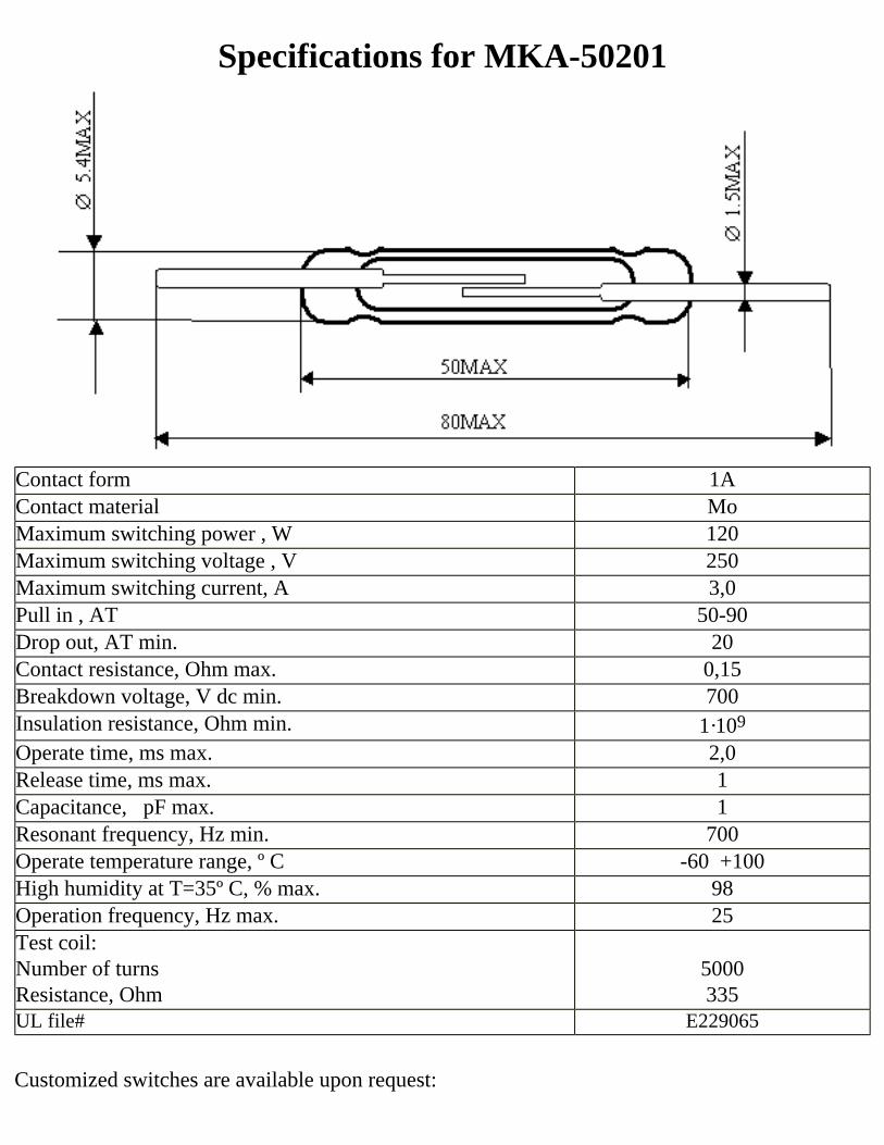
Specifications for MKA-50201
Contact form 1AContact material MoMaximum switching power , W 120Maximum switching voltage , V 250Maximum switching current, A 3,0Pull in , AT 50-90Drop out, AT min. 20Contact resistance, Ohm max. 0,15Breakdown voltage, V dc min. 700Insulation resistance, Ohm min. 1·109
Operate time, ms max. 2,0Release time, ms max. 1Capacitance, pF max. 1Resonant frequency, Hz min. 700Operate temperature range, º C -60 +100High humidity at T=35º C, % max. 98Operation frequency, Hz max. 25Test coil:Number of turnsResistance, Ohm
5000335
UL file# E229065
Customized switches are available upon request:

- with close PI values;- with cut, bent, flat leads;
Life expectancy and reliabilityTest modes:24V-0,25A-1x10⁶ operations min. at operation frequency of 25 Hz with failure rate 3,3x10 –8 oper -1. min., confidence level of 60%.220V-0,55A-1x10⁴ operations min. at operation frequency of 10 Hz with failure rate 3,3x10 –6 oper -1. min., confidence level of 60%.These data are valid for a coil energized at 1.5 times stated max. operate value.ShockReed switches are immune to mechanical shocks with peak shock acceleration of 150 g and impulse duration of 2 ms.VibrationReed switches are immune to sinusoidal vibration at 1-500 Hz and acceleration amplitude of 10 g.

0.1
1
510
203040
4040
0
60
20
30
40
50
60 80 100 ,
AT
80 120 160
50607080
90
95
99
99.9
0.1
1
510
20304050607080
90
95
99
99.9
(1) Drop-out vs. Pull-in
(3) Breakdown voltage
(2) Contact resistance
(4) Insulation resistance
0
600
800
1000
400
60 80 100AT
DC:V
10 10 10 10 1010 11 12 14 15
0.1
1
510
203040
100 20 30 40 Êg
50607080
90
95
99
99.9
(5) Lead tensile strength
MECHANICAL CHARACTERISTICS
ELECTRICAL CHARACTERISTICS
20
20
40
MKA-50201
200
(DC100V)
ATPull-in
Breaking load
Pull-in
Insulation resistance
Bre
akdow
nvoltage
Dro
p-o
ut
Cum
ula
tive
freq
uen
cyper
cent
Cum
ula
tive
freq
uen
cyper
cent
Cu
mu
lati
ve
freq
uen
cyp
erce
nt
Contact resistance�m
�
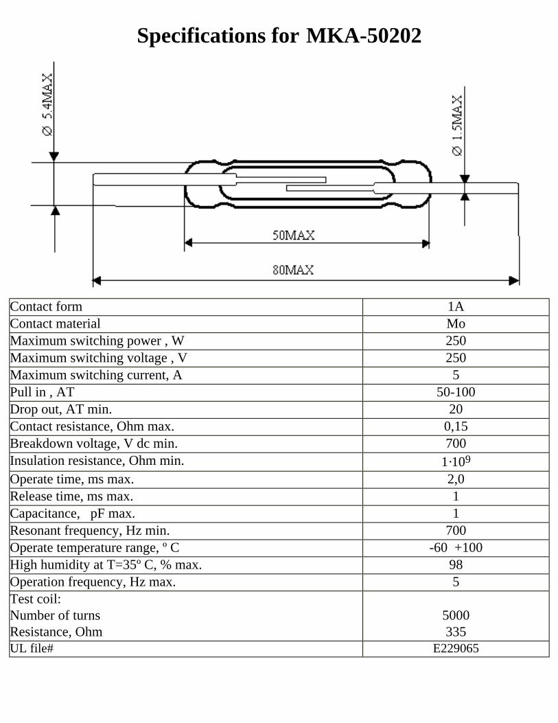
Specifications for MKA-50202
Contact form 1AContact material MoMaximum switching power , W 250Maximum switching voltage , V 250Maximum switching current, A 5Pull in , AT 50-100Drop out, AT min. 20Contact resistance, Ohm max. 0,15Breakdown voltage, V dc min. 700Insulation resistance, Ohm min. 1·109
Operate time, ms max. 2,0Release time, ms max. 1Capacitance, pF max. 1Resonant frequency, Hz min. 700Operate temperature range, º C -60 +100High humidity at T=35º C, % max. 98Operation frequency, Hz max. 5Test coil:Number of turnsResistance, Ohm
5000335
UL file# E229065

Customized switches are available upon request:- with close PI values;- with cut, bent, flat leads;
Life expectancy and reliabilityTest modes:250V-1A-1x10⁵ operations min. at operation frequency of 5 Hz with failure rate 3,3x10 –7 oper -1. min., confidence level of 60%.These data are valid for a coil energized at 1.5 times stated max. operate value.ShockReed switches are immune to mechanical shocks with peak shock acceleration of 150 g and impulse duration of 2 ms.VibrationReed switches are immune to sinusoidal vibration at 1-500 Hz and acceleration amplitude of 10 g.

0.1
1
510
203040
4040
0
60
20
30
40
50
60 80 100 AT
AT
80 120 160 m �
50607080
90
95
99
99.9
0.1
1
510
20304050607080
90
95
99
99.9
Contact resistancePull-in
(1) Drop-out vs. Pull-in
(3) Breakdown voltage
(2) Contact resistance
(4) Insulation resistance
Cum
ula
tive
frequency
perc
ent
Dro
p-o
ut
0
600
800
1000
400
60 80 100 AT
DC : V
Pull-in
Bre
akdow
nvoltage
10 10 10 10 1010 11 12 14 15 �
(DC 100V)
Insulation resistance
Cum
ula
tive
frequency
perc
ent
0.1
1
510
203040
100 20 30 40 kg
50607080
90
95
99
99.9
Breaking load
(5) Lead tensile strength
Cum
ula
tive
frequency
perc
ent
MECHANICAL CHARACTERISTICS
ELECTRICAL CHARACTERISTICS
20
20
40
MKA-50202
200

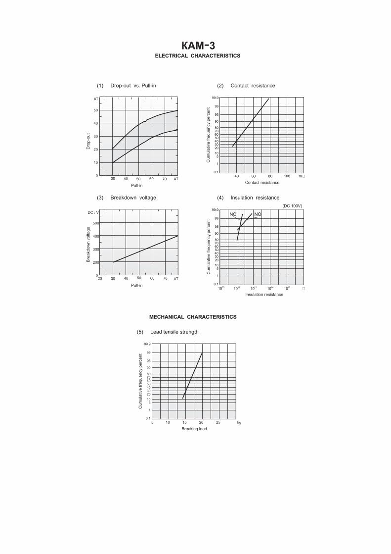
Specifications for KAM-3
Contact form 1CContact position, mm 11,0Contact material RuMaximum switching power , W 30Maximum switching voltage , V 125Maximum switching current, A 1,0Pull in , AT 30-80Drop out, AT min. 10Contact resistance, Ohm max. 0,15Breakdown voltage, V dc min. 180 AT≤55
280 AT>55Insulation resistance NC/NO, Ohm min. 2·108/1•109
Operate time, ms max. 1,5Release time, ms max. 2,0Capacitance NC/NO, pF max. 2,5/0,5Resonant frequency, Hz min. 3000Operate temperature range, º C -60 +100High humidity at T=35º C, % max. 98Operation frequency, Hz max. 50Test coil:Number of turnsResistance, Ohm
5000455
UL file# E229065

Customized switches are available upon request:- with close PI values;- with cut, bent, flat leads;
Life expectancy and reliabilityTest modes:24V-250mA-5x10⁵ operations min. at operation frequency of 50 Hz with failure rate 6,7x10 –8 oper -1. min., confidence level of 60%.5V-10mA-1x10⁶ operations min. at operation frequency of 50 Hz with failure rate 3,3x10 –8 oper -1. min., confidence level of 60%.These data are valid for a coil energized at 1.5 times stated max. operate value.ShockReed switches are immune to mechanical shocks with peak shock acceleration of 150 g and impulse duration of 1 ms.VibrationReed switches are immune to sinusoidal vibration at 1-600 Hz and acceleration amplitude of 10 g.
0.1
1
510
203040
4040
0
10
20
30
40
50
50 60 70 AT
AT
60 80 100 m �
50607080
90
95
99
99.9
0.1
1
510
20304050607080
90
95
99
99.9
Contact resistancePull-in
(1) Drop-out vs. Pull-in
(3) Breakdown voltage
(2) Contact resistance
(4) Insulation resistance
Cum
ula
tive
frequency
perc
ent
Dro
p-o
ut
0
200
300
400
500
30 40 50 AT
DC : V
Pull-in
Bre
akdow
nvoltage
10 10 10 10 1010 11 12 14 15 �
(DC 100V)
Insulation resistance
Cum
ula
tive
frequency
perc
ent
0.1
1
510
203040
105 15 20 25 kg
50607080
90
95
99
99.9
Breaking load
(5) Lead tensile strength
Cum
ula
tive
frequency
perc
ent
MECHANICAL CHARACTERISTICS
ELECTRICAL CHARACTERISTICS
7060
30
20
ÊAÌ 3-
NC NO

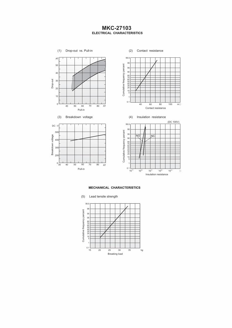
Specifications for MKC-27103
Contact form 1CContact position, mm 17,0Contact material RuMaximum switching power , W 30Maximum switching voltage , V 200Maximum switching current, A 1,0Pull in , AT 45-90Drop out, AT min. 16Contact resistance, Ohm max. 0,15Breakdown voltage, V dc min. 350Insulation resistance NC/NO, Ohm min. 5·108/1•109
Operate time, ms max. 1,5Release time, ms max. 2,5Capacitance NC/NO, pF max. 2,0/1,0Resonant frequency, Hz min. 2200Operate temperature range, º C -60 +100High humidity at T=35º C, % max. 98Operation frequency, Hz max. 50Test coil:Number of turnsResistance, Ohm
5000450
UL file# E229065
�

Customized switches are available upon request:- with close PI values;- with cut, bent, flat leads;
Life expectancy and reliabilityTest modes:30V-100mA-5x10⁵ operations min. at operation frequency of 10 Hz with failure rate 6,7x10 –8 oper -1. min., confidence level of 60%.60V-200mA-1x10⁵ operations min. at operation frequency of 10 Hz with failure rate 3,3x10 –7 oper -1. min., confidence level of 60%.These data are valid for a coil energized at 1.5 times stated max. operate value.ShockReed switches are immune to mechanical shocks with peak shock acceleration of 150 g and impulse duration of 1 ms.VibrationReed switches are immune to sinusoidal vibration at 1-1000 Hz and acceleration amplitude of 10 g.
0.1
1
510
203040
4040
0
10
20
30
40
50
50 60 70 AT
AT
60 80 100 m �
50607080
90
95
99
99.9
0.1
1
510
20304050607080
90
95
99
99.9
Contact resistancePull-in
(1) Drop-out vs. Pull-in
(3) Breakdown voltage
(2) Contact resistance
(4) Insulation resistance
Cum
ula
tive
frequency
perc
ent
Dro
p-o
ut
0
200
300
400
500
30 40 50 AT
DC : V
Pull-in
Bre
akdow
nvoltage
10 10 10 10 109 10 11 12 13 �
(DC 100V)
Insulation resistance
Cum
ula
tive
frequency
perc
ent
0.1
1
510
203040
2015 25 30 35 kg
50607080
90
95
99
99.9
Breaking load
(5) Lead tensile strength
Cum
ula
tive
frequency
perc
ent
MECHANICAL CHARACTERISTICS
ELECTRICAL CHARACTERISTICS
7060
80
80
MKC-27103
NO NC