ree- ying insp ection rob ot in space. - ri.cmu.edu · cam igd under vxw orks. it comm unicates via...
TRANSCRIPT

Path Planning and Control for AERCam, a Free- ying Inspection Robot in
Space.
Howie Choset David Kortenkamp
Carnegie Mellon University Texas Robotics and Automation Center
Scaife Hall Metrica, Inc.
Pittsburgh, PA 15213 Houston, TX 77058
ABSTRACT
This paper describes a prototype robot and the necessary path planning and control for space inspection appli-
cations. The robot is the �rst generation of a free- ying robotic camera that will assist astronauts in constructing
and maintaining the Space Station. The robot will provide remote views to astronauts inside the Space Shuttle
and future Space Station, and to ground controllers. The �rst part of the paper describes a planar robot prototype
autonomously moving about an air bearing table. The second part of this paper introduces a method for determining
paths in the three-dimensions for e�cient fuel use. Finally, this paper describes the software simulation of the path
planner with the future space station.
1 INTRODUCTION
AERCam (Autonomous Extra-vehicular Robotic Camera) is designed to provide astronauts and ground control
camera views of the space shuttle and station. The �rst generation of AERCam, called AERCam Sprint, ew on
a shuttle mission in December 1997. AERCam Sprint was teleoperated by an astronaut inside the space shuttle.
AERCam's only autonomy was its ability to automatically stop its rotation when commanded to do so. The
next generation of AERCam, called AERCam II, is currently in development at NASA Johnson Space Center.
This robot will have additional autonomous functionality and will be controlled by an intelligent layered control
architecture called 3T (Bonasso et al. , 1997).
This paper describes the path planning and control algorithms that direct AERCam's motions. First, we will
describe the planar prototype for AERCam and the planar path planning algorithm that directs it. This path
planning algorithm is based on the generalized Voronoi diagram (GVD), which has been commonly used in the
motion planning �eld (Latombe, 1991). One of the contributions of this paper is that we use the GVD to locally
optimize fuel usage of AERCam on the air bearing table.
The second part of this paper then upgrades the planar path planning approach to three-dimensions using a new
motion planning structure called the generalized Voronoi graph (GVG), already described in prior work (Choset
& Burdick, 1995a). Again, we use the GVG initially to �rst �nd a path and then apply a similar optimization
technique to minimize fuel usage. Software simulations validate this approach for the space station.

2 PLANAR HARDWARE TESTBED
AERCam IGD is a testbed for a free- ying space robot. The AERCam IGD consists of several hardware
components and is shown in Figure 6. Although this paper is primarily about the software control algorithms of
AERCam, in this section we will brie y describe the major components of the hardware testbed.
� Flotation sled. In order to emulate the e�ects of a friction-less environment on our control algorithms,
the AERCam IGD robot oats on a thin layer of air above an air bearing table (ABT). This cushion of
air is provided by a otation sled, which bears the weight of AERCam. An on-board reservoir supplies air,
providing tether-free operation.
� Thrusters. AERCam IGD moves by �ring small nitrogen thrusters. There are eight thrusters: two in each
of four directions. By combining di�erent thruster �rings rotations and movements can be performed. An
on-board tank provides nitrogen for tether-free operation.
� Infrared detectors. AERCam IGD has a ring of twelve infrared detectors. These detectors provide a range
to objects ranging from six inches to 36 inches away. The range is given as one of sixteen steps between these
two distances. Each sensor provides data at approximately ten hertz.
� Processor. AERCam has an on-board Pentium 100 MHz processor on a PC-104 bus. The processor
runs VxWorks 5.3. The PC-104 bus provides slots for attaching additional cards, including cards for data
acquisition.
� Inertial Measurement Unit. AERCam IGD has a laser gyroscope that can measure accelerations in
both rotation and translation. Control software uses these measurements (plus additional data) to determine
AERCam's position and velocity.
� Vision. AERCam IGD has two color cameras mounted on its top surface. These camera have a �xed position
and a �xed verge (angle between the cameras). They are attached to a wireless video transmitter, described
in the next section.
� Communication. While a great deal of AERCam's real-time control is done on-board, some high-level
control, some perception and the user interface are o�-board the robot. AERCam has a wireless Ethernet
communication system that connects its on-board Pentium processor with o�-board workstations. AER-
Cam also has a wireless stereo video transmitter to provide a video feed to the user interface and o�-board
processors.
3 SOFTWARE COMPONENTS
The AERCam IGD contained a large number of software components written many di�erent people that has
been combined to allow for both teloperation and autonomous operation. Some of the software ran on-board the
IGD robot, but most ran on o�-board computers.

3.1 Motion Control System
The Motion Control System (MCS) of AERCam provides two functions: 1) determining AERCam's position;
and 2) performing real-time control of AERCam. Basic commands that the MCS can implement include: 1)
moving in any axis and rotating; 2) stopping; 3) moving to an x,y position; and 4) turning to an angle.
The MCS is a separate process running on-board the AERCam IGD under VxWorks. It communicates via
shared memory with the intelligent control system (see Section 3.5). The control laws and position determination
algorithms were written by experts on control of free- ying spacecraft and tested extensively in simulation and on
the air bearing table. This paper does not focus on the MCS, although its functioning is crucial to a successful
robot system, but instead focuses on the higher level planning and control that results in commands to the MCS.
A key component of the MCS is a Global Positioning System (GPS). This GPS consists of six pseudolites
(beacons that mimic GPS satellites indoors) and two receiving antenna's, one on AERCam and one o�-board as a
reference receiver. The GPS system uses di�erential measurements between the on-board and reference receiver to
determine AERCam's position. This position is combined with information from the Inertial Measurement Unit
and used to control AERCam. The GPS system was developed at Stanford University and modi�ed for use at
NASA JSC.
3.2 Path planning
This path planning algorithm used for the AERCam IGD is based on a geometric structure called a roadmap
(Canny, 1988). Sometimes, roadmaps are called skeletons because they capture the salient geometric structure of
an environment much like an animal's skeleton re ects the geometry of its body. Roadmaps have the following
properties: accessibility, connectivity, and departability. A robot uses a roadmap to plan a path by �nding a path
from the start onto the roadmap (accessibility), then along the roadmap (connectivity) and then from the roadmap
to the goal (departability). This is similar to how people use roadways, hence the term roadmap structure. Once
the robot determines the path from the roadmap, the path is then optimized for fuel usage. The �rst roadmap used
in this paper is the generalized Voronoi diagram (GVD), which has been commonly used in the motion planning
�eld ( �O'D�unlaing & Yap, 1985). One of the contributions of this paper is that we use the GVD to locally optimize
fuel usage of AERCam on the planar air table. Later, we will extend the GVD to three dimensions by introducing
the generalized Voronoi graph.
3.2.1 The generalized Voronoi diagram
The planar roadmap used in this work is the generalized Voronoi diagram (GVD). �O'D�unlaing and Yap
(�O'D�unlaing & Yap, 1985) �rst applied the GVD, which is the locus of points equidistant to two or more ob-
stacles, to motion planning for a disk in the plane.
To de�ne the GVD, assume the robot is a point operating in a work space, W, which is populated by convex
obstacles C1; : : : ; Cn. Non-convex obstacles are modeled as the union of convex shapes. The distance between
a point and an obstacle is the shortest distance between the point and all points in the obstacle. The distance

function, and its \gradient," respectively are
di(x) = minc02Ci
kx� c0k and rdi(x) =x� c0
kx� c0k;
where (1) di is the distance to obstacle Ci from a point x, and (2) the vector rdi(x) is a unit vector in the direction
from x to c0, where c0 is the nearest point to x in Ci.
The basic building block of the GVD is the set of points equidistant to two sets Ci and Cj , such that each point
in this set is closer to the objects Ci and Cj than any other object. We term this structure the two-equidistant
face,
Fij = fx 2 Rm : 0 � di(x) = dj(x) � dh(x) 8h 6= i; j
and rdi(x) 6= rdj(x)g:
A two-equidistant face has co-dimension one in the ambient space, and thus in the plane, a two-equidistant face is
one dimensional (Choset & Burdick, 1995a). The union of the two-equidistant faces forms the generalized Voronoi
diagram, i.e.,
GVD =n�1[
i=1
n[
j=i+1
Fij:
See Figures ?? for examples of the GVD. Note GVD edges terminate on the boundary at nodes termed boundary
points and at nodes termed meet points where other GVD edges terminate.
Now, we show how the robot can use the GVD for motion planning. Given an arbitrary start location for
AERCam, there always exists a path from the start to at least one point on the GVD. This path is described as
_c(t) = rdi(c(t))
where Ci is the closest object to the robot. Essentially, this path directs AERCam away from the closest obstacle
until it encounters another obstacle which is equidistant to the �rst closest obstacle. This accessibility property of
the GVD was show in ( �O'D�unlaing & Yap, 1985) but is restated here in terms of the distance function. Loosely
put, the GVD has the accessibility property because when the robot moves away from its closest object it must
encounter another object to which its is equidistant due to boundedness.
It is shown in (Choset & Burdick, 1995b), that all points in the free space are within at least one point on the
GVD. This means, when the robot negotiates the entire GVD, it is guaranteed to \see" the entire work space.
This feature furnishes the GVD with the property of departability.
So, we have shown that the robot can access the GVD and depart from it, and now we describe the intermediate
step | traversing the GVD from the access to the depart locations on the GVD. Since the GVD is connected
(Choset, 1996; �O'D�unlaing & Yap, 1985), we are guaranteed that there will be a path on the GVD between the
access and depart locations. This path is determined via a graph search of the GVD. The robot traverses an edge
until it encounters a meet point. Here, the robot search branches and another edge is traversed. If the robot
encounters a boundary point, it simply returns to a meet point with an un-searched edges associated with it. If

the robot encounters an already visited meet point, then there is a cycle in the graph and again, the robot returns
to a meet point with an unexplored edge associated with it. If a path exists, this procedure will terminate when
the robot becomes within line of sight of the goal, at which point the robot departs the GVD for the goal. See
Figure ??.
If no path exists between the start and goal, then this procedure terminates when all meet points have no
un-searched edges associated with them. The power of this procedure is that it determines a path when one exists
or reports failure when no path exists. Such a path planner is called complete.
3.2.2 Minimizing Fuel Usage
The planar AERCam uses its thrusters to move on the air table, thereby emulating space-like deployment.
Naturally, AERCam must �re its thrusters several times to follow an arbitrary path. In Figure ??, AERCam
would have to �re its thrusts several times to negotiate the curved portions of the GVD. Firing thrusters requires
fuel; fewer bursts requires less fuel thereby making the mission more cost-e�ective. Our goal is to minimize the
number of �rings AERCam requires to traverse from a start to a goal location.
Initially, we considered orbital mechanics calculations to optimize fuel usage. This proved to be unnecessary
because recently NASA researchers at the Johnson Space Center have shown that taking orbital dynamics into
account when doing AERCam-type navigation does not signi�cantly reduce fuel usage (Gonzalez, 1998). The
scientists concluded that a sequence of straight line paths from start to goal suitably approximates an optimal
solution for fuel usage.
Once the GVD-path is determined from the GVD, the straight-line-path-sequence optimization procedure is
quite simple: move along the GVD-path until the start location can no longer be seen. The last point where the
start is within line of sight is a \way-point" for AERCam. This procedure is then repeated with the way-point
serving as the start location until the goal is reached. The result is a sequence of way points that describe a
piece-wise linear path from start to goal.
This optimization procedure will produce paths that bring AERCam unacceptably close to obstacles, so the
operator speci�es a safety parameter describing the minimum distance to an obstacle AERCam is allowed to
achieve. The robot moves along the GVD-path from the start. Whenever the distance of the line segment de�ned
by the current robot location and start location falls below the safety threshold, the robot de�nes a way point.
This procedure is then repeated with the way point serving as the start location until the goal is reached. See
Figure ??.
3.3 Stereo vision
One goal of the AERCam IGD was to be able to maintain a �xed distance and heading to a person. To do
this an active stereo vision system was used. This vision software has been developed over a number of years at
NASA Johnson Space Center and Metrica/TRACLabs (Huber, 1994; Huber & Kortenkamp, 1995; Kortenkamp
et al. , 1996). When tracking an object it can provide the location of the object with respect to the camera. It
runs under Windows NT on a 300 Mhz Pentium II using four C80 DSP chips and operates at approximately ten
frames per second.
In order to e�ciently process the enormous amount of information available from stereo cameras, the system
uses techniques that have recently been developed by the active vision research community (Ballard, 1991; Coombs
& Brown, 1991). In particular, the system addresses the issue of gaze control, i.e., where to focus attention and
visual resources. In our vision system a Laplacian of a Gaussian convolution is performed on the image data
streams as they are simultaneously acquired. Only the sign of the LOG output is stored in memory. Then, a
search is performed in which a patch from the left LOG image is compared with a portion of the right LOG image,
producing correlation measurements. This search produces a series of correlations from which the strongest (the
\peak") is chosen as the best. At the same time, the right LOG image from the frame before is compared with
the current right LOG image to measure motion. This correlation data is used to assess information within a
bounded volume of space called a proximity space. Each proximity space is controlled by a set of behaviors. These
behaviors keep the proximity space on an object that is being tracked and the object's position is reported to the
intelligent control system so that the robot's motion can be determined. There is not enough room in this paper
to give a detailed account of the stereo vision system { see (Huber & Kortenkamp, 1997) for more information.
3.4 User interface
All commands to AERCam ow through a user interface. The user interface is implemented in C++ and runs
on a Pentium laptop running Windows 95. The user interface displays telemetry from AERCam and allows the
user to teleoperate AERCam using a joystick, to command AERCam to a position and to begin stereo tracking.
Figure 6 shows a screen dump of the AERCam user interface. The upper left panel in this �gure allows the user
to change control modes and the current tasks. The upper right panel allows the user to select a target to track.
The lower panels show a three dimensional view of AERCam's position and its path of travel. Users can click on
a point in the lower right panel and command AERCam to go to that location.
3.5 Intelligent control
In the AERCam IGD, high-level control of the robot was done using an intelligent control architecture called 3T
(Bonasso et al. , 1997). The 3T architecture separates the general intelligent control problem into three interacting
layers or tiers (and is thus known as 3T, see Figure ??).
� A set of hardware-speci�c situated skills that represent the architecture's connection with the world. The term
\situated skills" (Slack, 1992) is intended to denote a capability that will achieve or maintain a particular
state in the world.
� A sequencing capability that can activate the situated skills in order to direct changes in the state of the world
and accomplish speci�c tasks. This tier of the architecture is implemented using Reactive Action Packages
(RAPs) (Firby, 1987).
� A deliberative planning capability which reasons in depth about goals, resources and timing constraints. The
planning layer was not used in the AERCam IGD.
The skills and skill manager reside on-board the free- yer running under VxWorks. The sequencing layer runs
o�-board the free- yer on a Windows 95 machine. The two communicate via TCP/IP using the wireless ethernet.
3.6 Communication
All interprocess communication in this project was done using the IPC software package from Carnegie Mellon
University (approval to use IPC on this project was given by CMU). IPC supports the VxWorks, SunOS, IRIX,
Linus, System 7, MacOS 8.0, and Windows 95/NT operating systems. It supports the C, C++, Allegro Common
Lisp and Macintosh Common Lisp programming languages. It allows for dynamic recon�guration of processes and
both primitive and complex data structures.
IPC works on a publish/subscribe paradigm. That means that processes that have data publish that data as
prede�ned messages with an identi�er. Processes that need data subscribe to these prede�ned messages using
the identi�er. Whenever a message is published, the subscribing processes are noti�ed immediately. A central
router (called the central server) keeps track of which processes are publishing and subscribing to which messages
and routes the messages among them. IPC handles di�erences in byte ordering between di�erent computer
architectures.
4 EXPERIMENTS
Over a period of several months the AERCam IGD was tested on the air bearing table performing a variety of
tasks. These tasks included:
� Teleoperating the AERCam IGD using a joystick. At any time, AERCam can be commanded to halt.
� Teleoperating the AERCam IGD using voice commands. At any time, AERCam can be commanded to halt.
� Autonomous navigation of the AERCam to a speci�ed position using path planning.
� Tracking a moving human.
� Obstacle avoidance while navigating to a speci�ed position.
All of these tasks relied on a key set of skills. The sequencer (see Section 3.5) enabled the appropriate set of
skills depending on the task and on the situation. First, we will list the core set of skills. Then we will look at
each task and examine how the di�erent software components come together to perform each task.
4.1 Skills
Skills are 3T's interface to hardware and low-level robot processes. AERCam has a number of skills that can
be activated by the sequencer. The skills all run in VxWorks on-board the robot. A skill manager schedules the
skills and manages their data. The following are the core implemented skills:
� mcs interface: communicates with the motion control system (see Section 3.1) on-board the robot.
� thruster control: manages the eight AERCam thrusters.
� teleop: interprets joystick commands and produces appropriate AERCam commands.
� voice cont: interprets the voice system commands and produces appropriate AERCam commands.

� attitude hold: maintains the current AERCam attitude.
� translate hold: maintains the current AERCam position.
� turn to: generates the appropriate MCS command to turn AERCam to a given angle.
� move to: generates the appropriate MCS commands to move AERCam to a given position.
� �nd object: initiates a visual search using the stereo tracking system.
� track object: takes data on the object's location from the stereo tracking system and determines the appro-
priate movement for AERCam in order to track the object.
� obstacle avoid: examines the infrared sensor data and generates appropriate AERCam movement to avoid
any obstacles.
� battery state: monitors the battery and alerts the sequencer when the battery is running low.
� propellant level: monitors the on-board thruster propellant and alerts the sequencer when the propellant
is low.
There are a number of other skills that performmoremundane operations such as interfacing to various hardware
and software components. However, the skills given above allow the sequencer to task AERCam through a wide
variety of activities as will be described in the following subsections.
4.2 Teleoperation
The user interface contained a six degree-of-freedom joystick that could be used to command AERCam. The
user �rst needs to click on the user interface to request control of the robot. This sends an IPC message to
the sequencer, which stops any current robot activity and enables the teleop skill. The teleop skill then waits
for IPC messages generated by the user interface corresponding to joystick directives. This continues until the
teloperation mode is disabled at the user interface. Once teleoperation is disabled, the robot will not respond to
any joystick commands.
4.3 Voice
The voice system is commercial-o�-the-shelf voice recognition software. The user requests voice command from
the user interface. The sequencer shuts down other robot activity and turn on the voice control skill. While the
voice recognition system is always active, any commands it receives are be ignored by the robot unless it was in
the proper mode. Once in the proper mode, commands like `turn right', `move forward', `stop', etc. can be given.
The voice system generates an IPC message for each utterance and this is interpreted by the voice control skill
and an appropriate robot action is performed.
4.4 Autonomous navigation
To do autonomous navigation, the user selects a goal position by clicking their mouse on a drawing of the air
bearing table on a laptop computer. The goal position is sent to the sequencing layer of the architecture. The
sequencer requests a path from the path planner (described in Section 3.2). The path planner returns a list of via
points (or way points) that will move the AERCam robot safely through the environment to the goal position (or

it returns an error message stating that no path was found). The sequencer then steps through the via points,
activating the appropriate skills in the skill tier. Before sending a new via point, the sequencer checks to make
sure that the robot had successfully reached the current via point. If the robot was not successful, the sequencer
re-sends the original via point or takes other action (such as asking for a new path). The user can stop the robot's
navigation at any time by pressing a button on the laptop.
Figure 6 shows a sequencer script obtains a path, navigates the robot to each via point in the path and then
turns the robot to a �nal orientation. The actual RAP scripts used in AERCam are more complicated with
more checking of robot state and conditional execution paths. The actual RAP scripts also conform to the RAP
language, while the example in the �gure is in a pseudo-code scripting language. Each step in the RAP script may
be another RAP that has its own script or it may be a primitive skill that is then activated.
4.5 Tracking
To track an object or person, the AERCam operator opens the tracking window on the graphic user interface
(GUI), which shows the video image from the robot's left camera. The operator positions and sizes a selection box
around the object to be tracked and clicks the tracking button. This sends an IPC message to the RAPs sequencer
with the coordinates for the box and the command to try to track the object there. The sequencer enables the
find object skill with these coordinates (top, bottom, left, right), narrowing the search space for the skill. Then
it enables the track object skill, which holds a constant distance from the tracked object. Figure 6 shows pseudo
code for this tracking sequence. The monitor-state means that this fact must remain true during execution of the
sequence, i.e., that the robot is in the right position for tracking. The context of the script states those things
that must be true before the script can execute, it is possible to have multiple sequences for di�erent contexts.
The stereo vision system tracks the moving person and sends their location in camera coordinates via IPC to
the skill manager. A new update is available approximately ten times a second. The track object skill converts
the location into world coordinates and determines a location for the robot to move to in order to stay a �xed
distance away from the person and in order to stay facing the person. This location is passed the the MCS for
execution.
In our experiments, we could track a person who moved at a very slow walk for periods of up to �fteen minutes
(limited by the amount of on-board propellant). If the vision system lost the person it automatically performed
a search and reacquired the person. Unfortunately, space does not permit a complete detailing of how the vision
system acquires and reacquires a moving person. See (Huber & Kortenkamp, 1997) for more details.
4.6 Obstacle avoidance
AERCam has a ring of twelve infrared sensors that give a distance to obstacles around AERCam. Obstacle avoid-
ance mode can be initiated from the user interface. This causes the sequencer to start the obstacle avoidance
skill, which reads all twelve infrared sensors and determines if there is an obstacle in the path of AERCam. An
obstacle is signalled if any infrared sensor reads an obstacle within thirty inches for three straight readings. When

an obstacle is detected, the MCS is signalled to immediately halt the robot. The user then needs to reselect the
goal location after verifying that the robot's path is free of obstacles.
5 THREE-DIMENSIONAL PATH PLANNING
The two-dimensional testbed described in this paper is only a �rst step in producing a free- ying robot for
space applications. Many important research issues need to be addressed in the move to three-dimensional envi-
ronments. Path planning in three dimensions is both computationally complex and non-intuitive. A free- ying
robot, such as AERCam, or a person teleoperating this robot, can eliminate this complexity and acquire an intu-
itive solution using a geometric structure termed a roadmap. With the roadmap in-hand, path planning becomes
computationally e�cient because the search takes place on the one-dimensional roadmap as opposed to the ambient
three-dimensional space.
5.1 Roadmap De�nition: The Generalized Voronoi Graph
The roadmap de�ned in the previous section is limited to the planar case. In three dimensions, the set of points
equidistant to two obstacles is a two-dimensional set. Figure 6 has a rectangular and triangular based prism
enclosed by a rectangular prism. The dotted lines outline the locus of points equidistant to two obstacles. These
two-dimensional sheets comprise the GVD.
Note that the two-dimensional sheets in Figure 6 intersect on a one-dimensional manifold. These one-
dimensional edges form our roadmap in three-dimensions. Let Fijk be a three equidistant face that is de�ned
by the intersection of two-equidistant faces Fij;Fik, and Fjk, i.e., Fijk = FijTFikTFjk. The pre-image theorem
asserts that the three-equidistant faces are indeed one-dimensional. The union of the three-equidistant face is
termed the generalized Voronoi graph, i.e.,
GVG =i=n�2[
i=1
j=n�1[
j=i+1
k=n[
k=j+1
Fijk:
Figure 6 has a GVG, for a simple three-dimensional rectangular enclosure with a box on the side. The ceiling is
removed so the GVG can be viewed.
5.2 Minimize Fuel Usage with the GVG
Variables such as fuel, safety, and time must be optimally budgeted for e�ective long-term use of AERCam.
The AERCam in space will also have a suite of thrusters to e�ect motion. AERCam must �re its thrusters several
times to following an arbitrary path. Hence, the GVG path, by itself, is not optimal for fuel usage (just as the
GVD in Section 3.2.2 was not optimal in the planar case).
Again, we do not have to consider orbital mechanics to optimize a path determined by the GVG because of the
result found in (Gonzalez, 1998). Instead, we use the same optimization routine that is described in Section 3.2.2
to determine a sequence of safe piece-wise linear path from start to goal in three-dimensions.
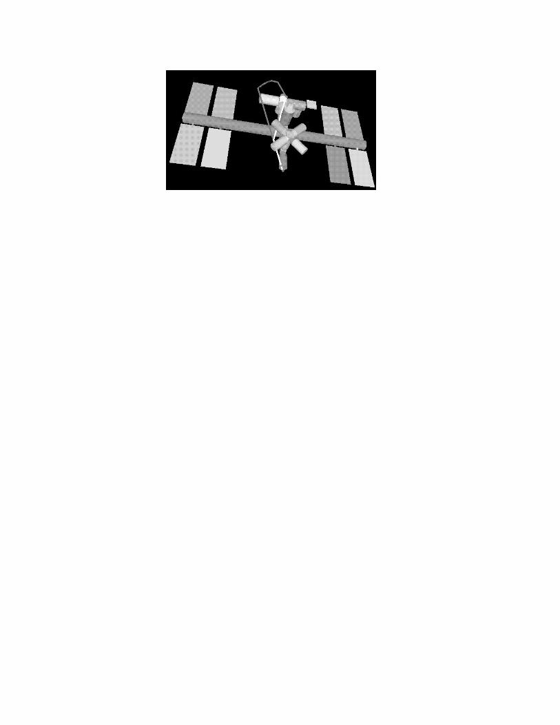
Figure 6 contains the space station, the GVG, and a path that brings AERCam from a start location to a
goal location along the GVG. This path is then optimized to minimize the number of thruster �rings. The space
station, with the GVG path and its optimized path, is shown in Figure 6. Note how the optimized path severely
cuts the corners.
6 CONCLUSION
The ultimate goal of this work is to enable AERCam, a free- ying robot, to autonomously y around the space
station to look for aws in its hull. This paper describes two necessary component to achieve this goal; these
components are path planning and control. The three-dimensional path planner uses the generalized Voronoi
graph (GVG) method and the control was based on an intelligent layered control architecture called 3T.
Before considering the full three-dimensional problem, we used a planar analog to AERCam. This planar robot
oated on a thin cushion of air and used small nitrogen thrusters to move. Naturally, if the robot �red a thruster,
it would move until either another thruster �ring stops it or until the robot collides with an object. This planar
system is complicated enough to capture many of the features involved with a free- ying space robot, while simple
enough to demonstrate the concepts in a short amount of time.
The �rst concept demonstrated what the path planning which used a roadmap called the generalized Voronoi
diagram (GVD). A robot uses the GVD to plan paths between any two points in an environment by �rst �nding a
path onto the GVD, then along the GVD, and then from the GVD to the goal. We then optimize this path with
respect to fuel usage and safety.
The second concept demonstrated was the intelligent control architecture. The architecture separates the real-
time control of the robot from the more deliberative aspects of intelligent behavior. It is the control architecture
that interacts with the robot user and interprets her commands. The control architecture then calls the three-
dimensional path planner when necessary. When a path is returned, the control architecture navigates the robot
along the path while responding to anomalous conditions.
Upon the successful completion of the planar experiments, we upgraded the technology to handle three-
dimensional environments. Therefore, this paper also described a three-dimensional path planning technique
and its application to free- ying space robot. The three-dimensional path planner uses the generalized Voronoi
graph (GVG), which reduces three-dimensional search problems to one-dimensional search problems. The GVG
can also be incrementally constructed using range sensor data, which makes it amenable to sensor based construc-
tion, but we constructed the GVG inside a CAD model of the space station. An intelligent control architecture is
used to traverse the three-dimensional path and serves to coordinate path planning and execution.
Future work on this project includes using the GVG to localize the AERCam, which would be useful in the case
of GPS loses tracking. The localization procedure draws from the previous work of the authors' in mobile robot
localization. Essentially, we will exploit geometries encoded in the GVG to determine landmarks that the robot
can use for localization. Another avenue of future research is using the HGVG to plan optimal inspection paths
for AERCam.
References
Ballard, Dana H. 1991. Animate Vision. Arti�cial Intelligence, 49(1).
Bonasso, R. Peter, Firby, R. J., Gat, E., Kortenkamp, David, Miller, D., & Slack, M. 1997. Experiences with an
Architecture for Intelligent, Reactive Agents. Journal of Experimental and Theoretical Arti�cial Intelligence,
9(2).
Canny, J.F. 1988. The Complexity of Robot Motion Planning. Cambridge, MA: MIT Press.
Choset, H., & Burdick, J.W. 1995a. Sensor Based Planning, Part I: The Generalized Voronoi Graph. In: Proc.
IEEE Int. Conf. on Robotics and Automation.
Choset, H., & Burdick, J.W. 1995b. Sensor Based Planning, Part II: Incremental Construction of the Generalized
Voronoi Graph. In: Proc. IEEE Int. Conf. on Robotics and Automation.
Choset, Howie. 1996. Sensor Based Motion Planning: The Hierarchical Generalized Voronoi Graph. Ph.D. thesis,
California Institute of Technology, Pasadena, CA, 91125.
Coombs, David J., & Brown, C. M. 1991. Cooperative gaze holding in binocular vision. In: Proceedings of the
Fifth IEEE International Symposium on Intelligent Control.
Firby, R. James. 1987. An investigation into reactive planning in complex domains. In: Proceedings of the National
Conference on Arti�cial Intelligence (AAAI).
Gonzalez, Rodolpho. 1998. Translation Maneuver DV Costs to the Solar Array, CW and Line Trajectories (NASA
Memo).
Huber, Eric. 1994. Object tracking with stereo vision. In: Proceedings of the AIAA/NASA Conference on
Intelligent Robots in Field, Factory, Service, and Space (CIRFFSS '94).
Huber, Eric, & Kortenkamp, David. 1995. Using Stereo Vision to Pursue Moving Agents with a Mobile Robot.
In: Proceedings of the IEEE International Conference on Robotics and Automation.
Huber, Eric, & Kortenkamp, David. 1997. A behavior-based approach to active stereo vision for mobile robots.
Engineering Applications of Arti�cial Intelligence, 11(1).
Kortenkamp, David, Huber, Eric, & Bonasso, R. Peter. 1996. Recognizing and interpreting gestures on a mobile
robot. In: Proceedings of the National Conference on Arti�cial Intelligence (AAAI-96).
Latombe, J.C. 1991. Robot Motion Planning. Boston, MA: Kluwer Academic Publishers.
�O'D�unlaing, C., & Yap, C.K. 1985. A \Retraction" Method for Planning the Motion of a Disc. Algorithmica, 6,
104{111.
Slack, Marc G. 1992. Sequencing Formally De�ned Reactions for Robotic Activity: Integrating RAPS and GAPPS.
In: Proceedings of SPIE's Conference on Sensor Fusion.


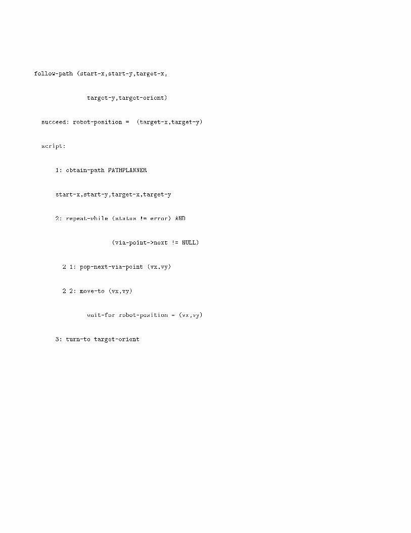
follow-path (start-x,start-y,target-x,
target-y,target-orient)
succeed: robot-position = (target-x,target-y)
script:
1: obtain-path PATHPLANNER
start-x,start-y,target-x,target-y
2: repeat-while (status != error) AND
(via-point->next != NULL)
2.1: pop-next-via-point (vx,vy)
2.2: move-to (vx,vy)
wait-for robot-position = (vx,vy)
3: turn-to target-orient

acquire-and-track (top bottom left right)
succeed: tracking-status = done
monitor-state: ff-positioned-for-tracking
script:
context: ff-positioned-for-tracking AND
NOT timeout
1. find-object top bottom left right timeout
2. track-object

Object
Voronoi Diagram (surface) Voronoi Vertex
VoronoiEdge


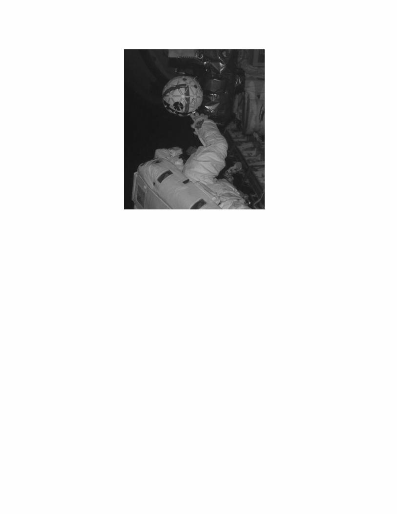
� AERCam space deployment.
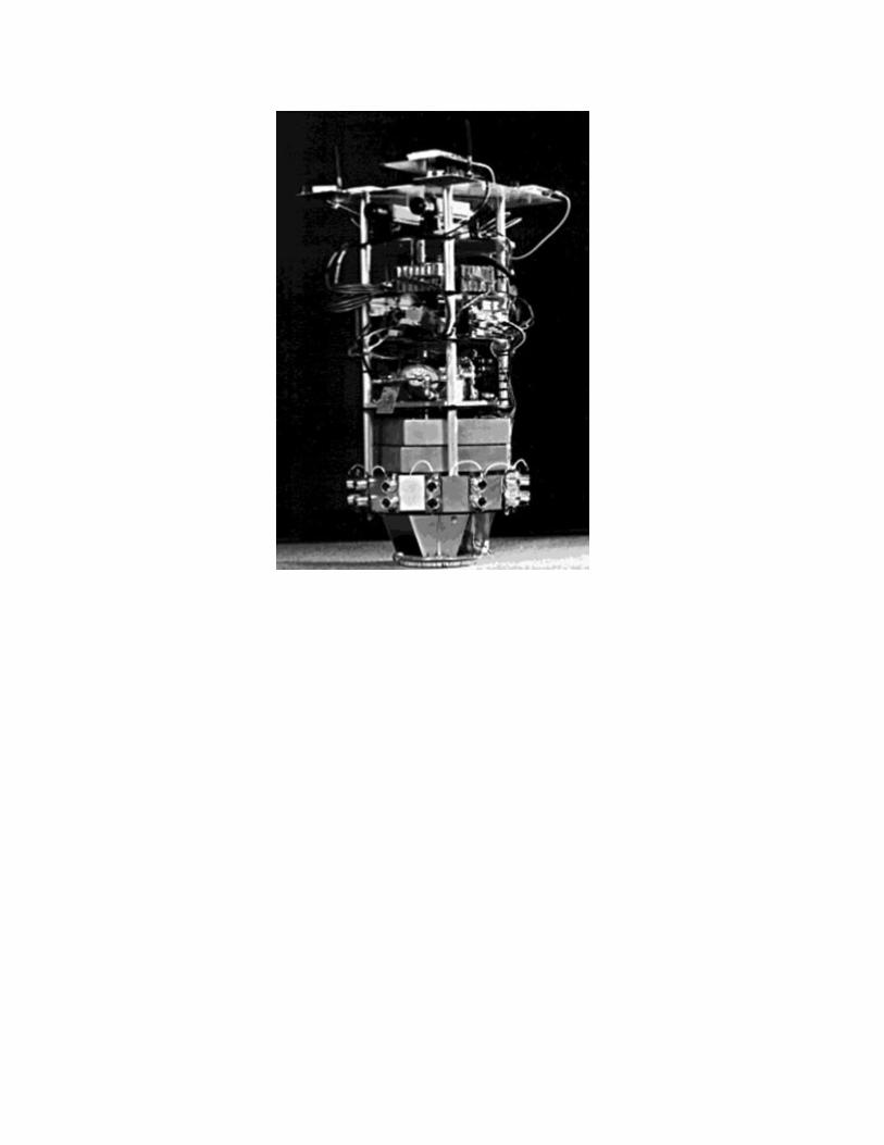
� The AERCam air bearing table robot.
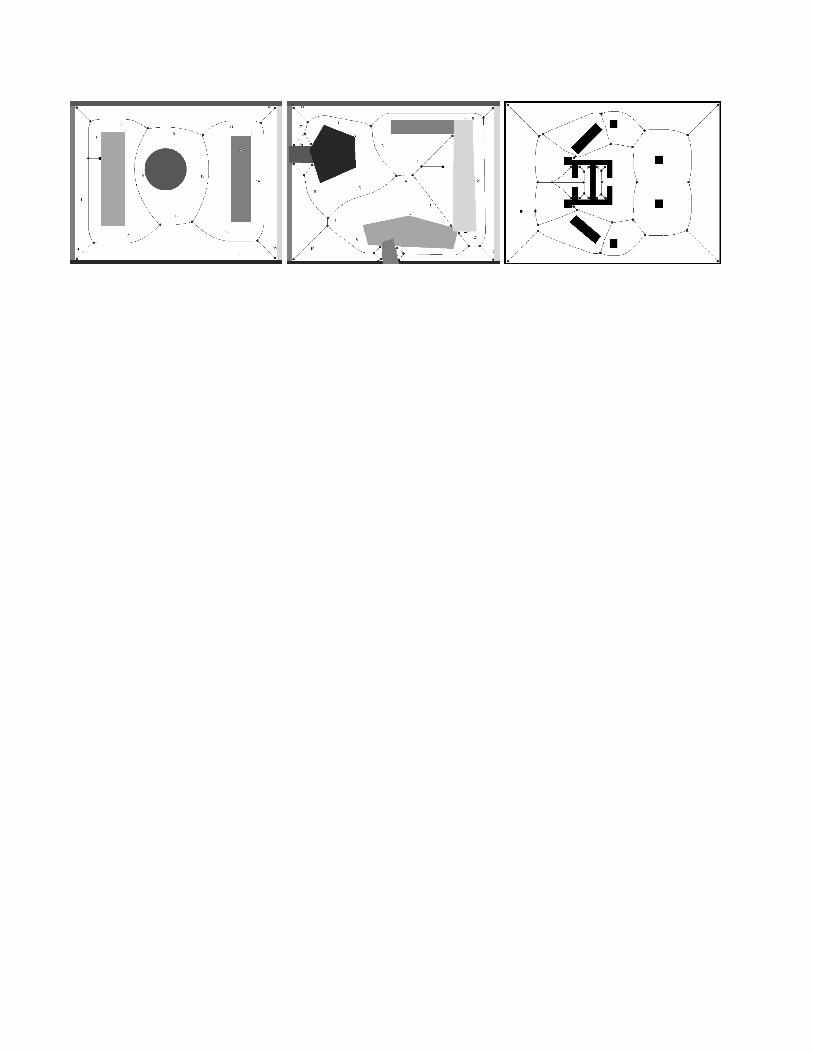
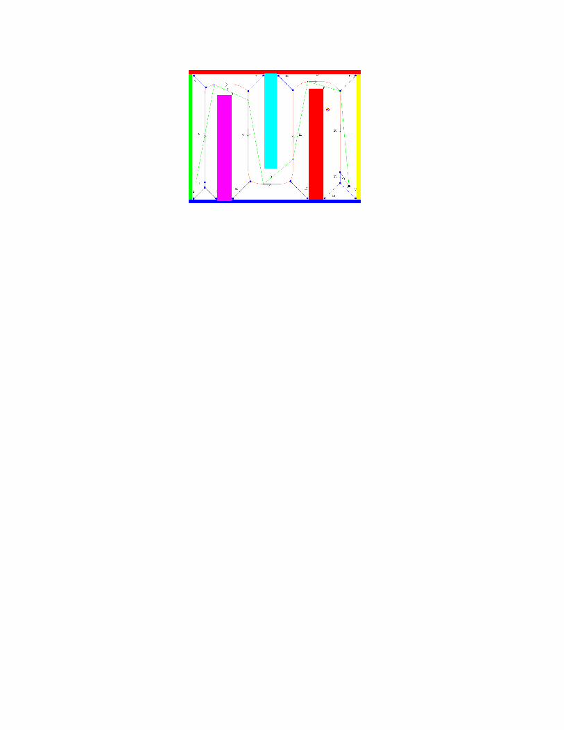
� The solid curve segments are the edges of GVD.
� AERCam determined a path from a start to a goal location by accessing the GVD, traversing the GVD, and
then departing the GVD.
� Using the GVD, AERCam determined a path as a sequence of straight line segments from a start to a goal
location.
� The 3T intelligent reactive control architecture. There are three tiers: a deliberative planner, a conditional
sequencer and reactive skills.
� AERCam's user interface.
� A sequence for following a path.
� A sequence for acquiring and tracking an object.
� Two-dimensional GVD in a three-dimensional world.
� Generalized Voronoi Graph (GVG) of a simple room with the ceiling removed. The GVG is the set of points
equidistant to three obstacles.
� Space station with GVG.
� Space station, path found with GVG, and optimized path.