reducing hot-section ceramic component cost and supporting ... filereducing hot-section ceramic...
TRANSCRIPT

Reducing Hot-Section Ceramic Component Cost And Supporting EBC Development Through Development of Nondestructive Evaluation
Technologies
W.A. Ellingson, E.R. Koehl, J. Stainbrook, C. Deemer, D. Muliere, and A. Parikh
Argonne National Laboratory Argonne IL, 60439
For Presentation to the DOE, Office of Power Technologies, Microturbine and Industrial Gas Turbine
Peer Review Meeting
Fairfax, VAMarch 12-14, 2002A
RG
ON
NE

Presentation Outline• Objectives• Improving yield of high volume production ceramic rotors
-Approach-Accomplishments (Primarily since last review 6-27-01)-Collaborations-Planned future work
• NDE Technology for development of EBC for monolithics-Approach -Accomplishments (Primarily since last review 6-27-01)-Collaborations-Planned future work
•Summary / Conclusion
AR
GO
NN
E

Objectives• Development of nondestructive non-contact
technologies for ceramic components under development for advanced, low-emission, high-efficiency microturbine and industrial gas turbines– Develop high-speed, low-cost, full-volume
nondestructive evaluation technology to improve ceramic rotor yield - hence reduce per-part cost.
– Develop nondestructive characterization technology for EBC coating development for monolithic and composite ceramic hot section components
AR
GO
NN
E

NDE Technology for High Volume Large Size Monolithic Components
AR
GO
NN
E

Approach[Ceramic Rotors]
•Develop a high spatial resolution 3D X-ray computed tomographic imaging system
- Work in direct cooperation with ceramic suppliers (Honeywell Ceramic Components and St. GobainIndustrial Ceramics)- CRADA with Perkin-Elmer/electro-optics on amorphous silicon flat panel X-ray detector- Cooperate with others developing flat panel cone beam 3D tomography
- William Beaumont Hospital, Michigan- Utilize existing ANL facilities such as parallel architecture computers, cooperation with DOE/BES funded staff at APS- Target is transfer technology to end user
AR
GO
NN
E
Parallel-beam Reconstruction
AR
GO
NN
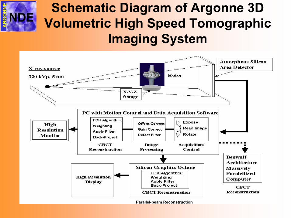
E Schematic Diagram of Argonne 3D Volumetric High Speed Tomographic
Imaging System

3D X-ray tomographic imaging setup with 40 cm by 40 cm amorphous silicon flat-panel
detector
AR
GO
NN
E

Flaw Zone 1
Flaw Zone 2
FULL-SIZED GELCAST AS 800 ROTORS USED FOR NDE/C STUDIES
AR
GO
NN
E

Accomplishments: 3-D High Speed X-ray Tomography
• Initial Defect -detection diagram for rotor established for steel inclusions and air-voids.– Current limits is mainly caused by pixel size,
400 µm of detector.– New 200 µm large area detector and 80 µm
line detector to be received in next 3 months.• Internal cracks in full sized rotor detected by
3 D full volume CT verified by destructive analysis.
• New Cooperative efforts started with DOE/BES/LTR with new 80 µm pixel detector
AR
GO
NN
E
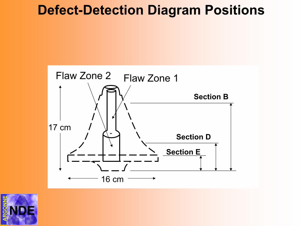
Flaw Zone 1Flaw Zone 2
16 cm
17 cm
Defect-Detection Diagram Positions
Section B
Section D
Section E
AR
GO
NN
E

Defect-Detection DiagramDefect Detection Diagram
0
5000
10000
15000
20000
25000
30000
35000
40000
45000
50000
0 0.2 0.4 0.6 0.8 1 1.2
Defect Diameter (mm)
Gra
ysca
le D
iffer
ence
178 mm Pins 112 mm Pins 67 mm Pins178 mm Void 112 mm Void 67 mm Void
AR
GO
NN
E

Section B (smallest)
parallel
conebeamA
RG
ON
NE
67 mm

Section D (middle)
parallel
conebeamA
RG
ON
NE
112 mm

conebeam
parallel
Section E (largest)
AR
GO
NN
E
178 mm

Crack is 200 microns wide
at this point
Crack is 280 microns wide
at this point
Crack is 90 microns wide
at this point
Crack is 90 microns wide at this point
FOR disc E
(largest disc)
AR
GO
NN
E
Crack size details for large diameter rotor section

Unbladed Rotor CT Slice and Line Profile-use of derivative for edge detection
Line Profile and Derivative
0
20000
40000
60000
80000
1 203Pixel
Gre
ysca
le V
alue
-15000
-10000
-5000
0
5000
10000
15000
Cha
nge
in G
reys
cale
Val
ue
Line Profile
Line Profile Derivative
Center Hole
Crack
AR
GO
NN
E

Full-size Bladed Gelcast AS800 Rotor
12 mm
The crack in the rotor was found to travel 8 mm horizontally as well as 40 mm vertically.
AR
GO
NN
E
High-speed data acquisition < 5 min.
High-speed volumetric image reconstruction
<12 min.

Bladed Rotor CT Slice and Line Profile
Line Profile and Derivative
0
20000
40000
60000
80000
1 400
Pixel
Gre
ysca
le V
alue
-8000
-4000
0
4000
8000
12000
Cha
nge
in G
reys
csal
e Va
lue
Line Profile
Line Profile Derivative
Crack
AR
GO
NN
E

Planned Future Work• Conduct various digital image processing studies to
improve and establish probability of detection for detail-detectability curves to allow better defect size detection prediction for various part sizes
• Verify additional detected features by destructive analysis (voids, density variation , cracks)
• Install and test 200 µm pixel large area detector• Install and test 80 µm pixel line detector• Continue efforts on fast reconstruction with target of
800x800x800 volume in less than <7 min• Establish best automated feature recognition digital image
method to advance automation of system; i.e. stand-alone• Continue discussions / cooperation with new industrial
partners
AR
GO
NN
E

NDE Technology for EBC’s
AR
GO
NN
E

• 6 monolithic AS800 vanes coated with EBC have been studied by elastic optical back-scatter NDE
• Initial destructive correlation established between back-scatter NDE data and thickness of EBC
• Free-standing EBC sample obtained and optical transmission characteristics initialed
• 6-axis articulated arm Robot installed, initial computer interfaceestablished, initial turbine vane and turbine blade CAD files transferred to robot
• First raster scan of simple flat plate done with 6-axis articulated robot arm
Accomplishments: EBC’sMonolithics

• Special set of MI SiC/SiC test samples obtained with UTRC EBC– delaminated– porosity– cracking
• One-sided thermal NDE acquired and analyzed for delamination• Optical transmission characteristics established from free-
standing EBC
Accomplishments: EBC’sComposites
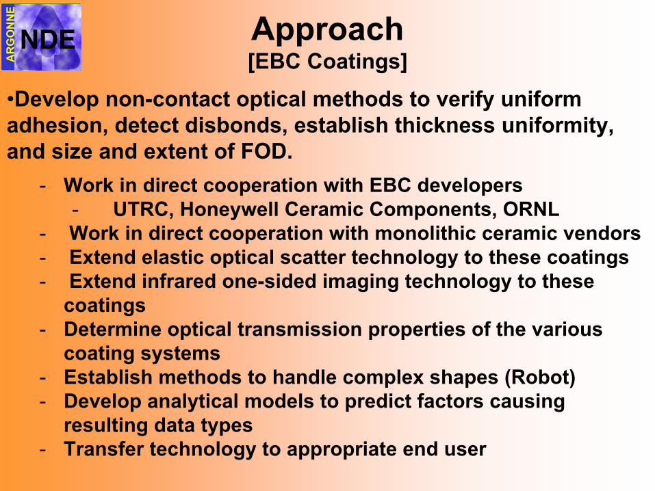
Approach[EBC Coatings]
•Develop non-contact optical methods to verify uniform adhesion, detect disbonds, establish thickness uniformity, and size and extent of FOD.
- Work in direct cooperation with EBC developers- UTRC, Honeywell Ceramic Components, ORNL
- Work in direct cooperation with monolithic ceramic vendors- Extend elastic optical scatter technology to these coatings- Extend infrared one-sided imaging technology to these
coatings- Determine optical transmission properties of the various
coating systems- Establish methods to handle complex shapes (Robot)- Develop analytical models to predict factors causing
resulting data types- Transfer technology to appropriate end user
AR
GO
NN
E

Schematic of elastic optical Schematic of elastic optical backscatter backscatter experimental test setupexperimental test setup
Ceramic Component onX•Y•Z•Φ
Translation/RotationStage
PBSCubes
ImagingLenses
λ/4 Plate
FocusingLens
50/50 BSCube
Detector A withPinhole Aperture
Detector B withWide Aperture
XY
ZΦ
25 mWHe-Ne Laser
CCDCamera
450 MHz Pentium PCwith Stage Controller and Scan Acquisition
Software
OpticalPowerMeter
Monitor
StageController
StageDriver
Incident Laser Beam(Polarized)
Surface Reflected Beam(Incident Polarization)
Transmitted Beam
Internal Scatter Internal Absorption
50% Cross Polarization
Polarized Object Lens
Detector A
Detector B AB
Distribution of Back-Scattered Light
With defect
Without defect
50% Incident Polarization
AR
GO
NN
E

ELASTIC OPTICAL SCATTERING NDE SYSTEM
PC
AR
GO
NN
E

Detection of pre-spall of EBC on AS 800 vane using elastic optical scatter
AR
GO
NN
E

Detection of erosion of EBC on AS 800 vane using elastic optical scatter
as received
542 hrs. 1621 hrs.
1621 hrs. as received
542
hrs.
1621 hrs.A
RG
ON
NE

Correlation EBC thickness to elastic optical scatter intensity on AS 800 vane after
1621hrs.
0
0.25
0.5
0.75
1
05101520
Distance from Top Platform (mm)
Norm
aliz
ed O
ptic
al L
aser
Sca
tter
23 mm87
6 µm
Optical Photo Micrograph
Elastic Optical Scatter Line Scan
Line Scan
Optical Photo Micrograph
Optical Laser ScatterImage
Photograph
Top Platform
Top Platform
Top Platform
AR
GO
NN
E

Recession of EBC thickness on AS 800 vane from elastic optical scatter intensity
As received 542 hrs. 1621 hrs.
Top Platform
Leading Edge Leading EdgeLeading Edge
LaserScans
Line Plots from LaserScans
AR
GO
NN
E
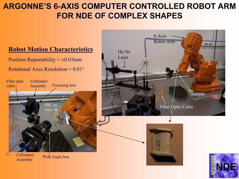
ARGONNE’S 6-AXIS COMPUTER CONTROLLED ROBOT ARM FOR NDE OF COMPLEX SHAPES
Robot Motion CharacteristicsPosition Repeatability = ±0.03mm
Rotational Axes Resolution = 0.01°Optics
Collimator Assembly Focussing lens
Fiber optic cable
Wide Angle lensCollimator Assembly
EBC on vane
He-Ne Laser
6-Axis Robot Arm
Fiber Optic Cable
Sample
AR
GO
NN
E

EBC SEEDED DEFECT COUPONS FOR NDE
-DELAMINATIONS-
AR
GO
NN
E
Test Samples Provided by UTRC

THERMAL IMAGING NDE EXPERIMENTAL APPARATUS
Detector
- 256x256, InSb, 200 mm- 12-bit dynamic range- Full window frame rateto 120 Hz
- 64x64 window frame rateto 1900 Hz.
- Typical flash pulse widthapprox. 6.0 ms
AR
GO
NN
E
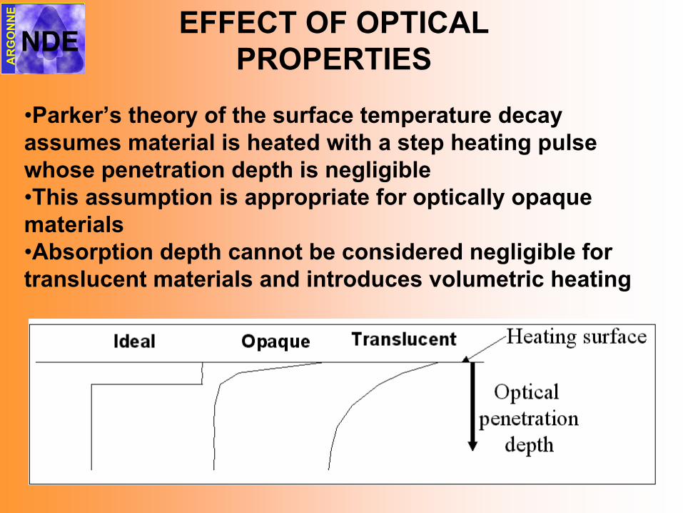
EFFECT OF OPTICAL PROPERTIES
•Parker’s theory of the surface temperature decay assumes material is heated with a step heating pulse whose penetration depth is negligible•This assumption is appropriate for optically opaque materials•Absorption depth cannot be considered negligible for translucent materials and introduces volumetric heating
AR
GO
NN
E

OPTICAL SPECTRAL ENERGY DISTRIBUTIONS OF
ARGON FLASH LAMPS
AR
GO
NN
E

ONE SIDED THERMAL IMAGINGOF SEEDED COUPON
.1 sec
.2 sec
.3 sec
.5 sec
.4 sec
.6 sec
Diffusivity Map
.7 sec
.8 sec
If volumetric heating was significant, seeded delaminationwould be indistinguishable from non-flawed regions
closest to surface
AR
GO
NN
E

Future Plans for EBC• Examine correlation's of NDE data on Rolls-Royce/Allison
EBC test specimens with additional destructive analysis• Determine effects of other EBC systems, specimens from
UTRC, on the NDE response signals• Conduct limited impact damage test, examine specimen
(AS800/Honeywell EBC) with laser scatter data, and one-sided thermal imaging
• Establish optical transmission characteristics of free-standing EBC (Honeywell and perhaps UTRC)
• Conduct one-sided NDE studies of special test samples of MI SiC/SiC with UTRC EBC [BSAS/mixed]
• Obtain new set of MI SiC/SiC samples with SAS/mixed EBC• Conduct optical transmission characteristics of SAS and
SAS/mixed
AR
GO
NN
E
Monolthics
Composites

Summary/Conclusions• Have demonstrated a technology which may reduce ceramic rotor
cost through improved yields via full volume 3D X-ray imaging. This is well under way
• Results of full volume 3D CT suggest detection of < 400 um features in rotor up to 23cm in diameter
• 3D CT data also allows dimensional data but accuracy not yet established
• Automation of 3D X-ray image data via use of automated feature detection will be pursued in next 12 months
• Elastic optical laser scattering and thermal imaging technology is under development to characterize EBC coatings for uniform thickness, detecting and sizing delaminated regions, estimating size and extent of FOD
• Elastic optical laser scattering appears to provide a fast and accurate means to monitor coating thickness on of EBCs
• One-sided thermal imaging while full field and fast, currently seemsless sensitive to features
• Extensive cooperation has been established with many partners
AR
GO
NN
E
Summary/Conclusions• Selected, purchased, installed, and initially tested 6-axis articulated
arm robot in order to handle complex shapes like blades and vanes• One-sided thermal imaging while full field and fast, currently seems
less sensitive to features• Extensive cooperation for all aspects of this project has been
established with many partners
AR
GO
NN
E