reduced activation materials - stanford university · d-t fusion reaction • the power production...
TRANSCRIPT

Reduced Activation Materials
Nadine Laurence Baluc
Centre of Research in Plasma PhysicsAssociation EURATOM - Swiss Confederation
Swiss Federal Institute of Technology - Lausanne

Introduction toEffects of Radiation Damage

D-T Fusion Reaction
• The power production process which can occur at the lowest temperature and, hence, the most readily attainable fusion process on Earth is the combination of a deuterium nucleus with one of tritium.
4He, 3.5 MeV
deuteriumnucleus
tritiumnucleus
neutron14.1 MeV

On the Use of 14 MeV Neutrons
• Breeding blanket: the kinetic energy of 14 MeV neutrons is transformed into heat that is transferred to a coolant.
• The produced vapor is used to run a turbine that produces electricity.

On the Impact of 14 MeV Neutrons on Materials
• The fusion neutrons produce atomic displacement cascadesand transmutation nuclear reactions within the materials.
• The materials can become radioactive.
deuteriumnucleus
tritiumnucleus
neutron14.1 MeV
4He, 3.5 MeV
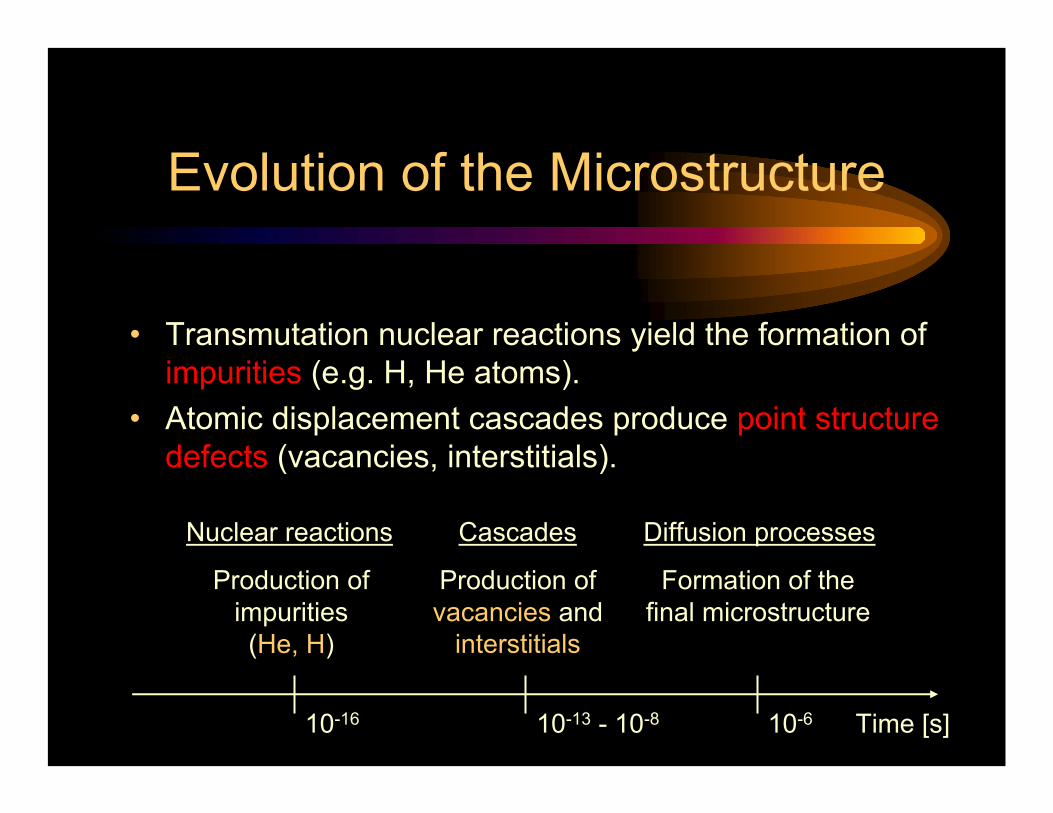
Evolution of the Microstructure
• Transmutation nuclear reactions yield the formation of impurities (e.g. H, He atoms).
• Atomic displacement cascades produce point structure defects (vacancies, interstitials).
Nuclear reactions Cascades
Production of impurities (He, H)
Production ofvacancies and
interstitials
Diffusion processes
Formation of the final microstructure
Time [s]10-610-13 - 10-810-16

Evolution of the Microstructure
• The microstructure of the irradiated material results from interactions between the various irradiation-induced defects. It can be formed of:
• Small defect clusters• Dislocation loops• Stacking fault tetrahedra• Precipitates• Voids• He bubbles
Dislocation loops
Voids
Stacking fault tetrahedra
200 nm
50 nm
10 nm

Evolution of the Properties
• Chemical composition:• Change in the chemical composition• Physical properties:• Decrease of electrical conductivity (low temperatures)• Decrease of thermal conductivity (ceramic materials)• Mechanical properties:• Hardening (H)• Loss of ductility (LD)• Loss of fracture toughness• Loss of creep strength• Dimensions:• Swelling, irradiation creep, irradiation growth• Environmental effects:• Irradiation-assisted stress corrosion cracking• Radioactivity:• Activation effects
stress
strain
H
LD
unirradiated
irradiated

Key Irradiation Parameters
• The final microstructure results from a balance between radiation damage and thermal annealing
• Key irradiation parameters:• Accumulated damage (in dpa)• Damage rate (in dpa/s)• Rate of production of impurities (e.g. He/dpa, H/dpa ratios)• Temperature
dpa = number of displacements per atom

Evolution of the Properties
• Low temperatures (e.g. < 400°C for steels):• Embrittlement effects: hardening, loss of ductility, loss of fracture
toughness, increase in DBTT (bcc materials)• Intermediate temperatures (e.g. 300-600°C for steels):• Swelling: peaks at about 450°C for RAFM steels• High temperatures (e.g. > 600°C for steels):• Enhanced precipitation effects• Enhanced creep effects
• Critical temperatures are dependent on the material and the irradiation conditions

Current Irradiation Facilities
• The existing sources of 14 MeV neutrons have a small intensity and do not allow to get important damage accumulation in a reasonable time.
• It is then necessary to simulate irradiation by 14 MeV neutrons, by using for instance fission neutrons.
• In Switzerland, we are using a mixed spectrum of high energy (590 MeV) protons and spallation neutrons (SINQ facility), which produce atomic displacement cascades and transmutation nuclear reactions, like fusion neutrons, within the irradiated material.

The Swiss Spallation Neutron Source (SINQ)
SINQ target

Irradiation Modes
• Fusion neutrons, fission neutrons, SINQ:• Strong differences in the production rate of impurities
~ 450~ 1040-50Hydrogen [appm/dpa]
~ 50~ 110-15Helium [appm/dpa]
~ 10~ 2020-30Damage rate [dpa/year]
Mixed spectrum of high energy protons
and spallation neutrons (SINQ)
Fission neutrons(BOR 60 reactor)
Fusion neutrons(3-4 GW reactor)
Defect poduction(in steels)

Materials for Fusion Reactors

Main Irradiated ComponentsBreeding blanket
Divertor
First wall
EFDA DATA

First Wall
• Plasma facing components:• First wall• Magnetic divertor
• First wall:• Forms the plasma chamber.• Serves as part and protection of the breeding blanket.
• The first wall consists of:• A structural material attached to a plasma facing (armor) material.

• Breeding Blanket:• Absorbs the 14 MeV neutrons, transforming their energy to provide
most of the reactor power output.• Shields the superconducting coils and other outer components.• Allows for neutron multiplication and breeding of Tritium to fuel the
reactor.
• A breeding blanket consists of:• A tritium breeding material (Li-containing alloy)• A neutron multiplier (Be)• A coolant (water, He and/or Pb-Li)• A structural material (to separate and contain the different materials)
Breeding Blanket
} Functional materials

• Magnetic divertor:• (a) Minimizing the impurity content of the core plasma• (b) Removing the α particle power• (c) Pumping the He ash
• The magnetic divertor consists of:A structural material (heat sink) which contains a coolant (water or He) and supports a plasma facing (armor) material.
Divertor

Structural Materials
• The qualification of structural materials is fundamental.• The thermal efficiency of a reactor is proportional to:
– The temperature of the coolant at the exit of the reactor.– The difference between the temperature of the coolant at the
exit of the reactor and the temperature of the coolant at the entrance of the reactor.
• These temperatures are mainly limited by the temperature window of use of the structural materials.
• The temperature window of use of the structural materials is mainly imposed by their mechanical properties under irradiation.

Functional Materials
• The qualification of functional materials is also very demanding:– Their mechanical properties under irradiation is not a primary
concern.– But properties, like the tritium release behavior, the thermal
conductivity or the entire structural integrity after prolonged neutron irradiation, are an important concern.
• The lack of adequate functional materials meeting very high temperature design window is an important issue for fusion power reactors.

Functional Materials
Water of heliumWater or helium and/or eutectic
Pb-Li-Coolant
-Li, eutectic Pb-Li, Li-base ceramic
material-Tritium breeding
material
-Be-Neutron multiplier material
DivertorBreeding blanketFirst wallFunction
• The choice of functional materials is very limited as it depends on the required properties.

Materials for ITER

Environmental Conditions
• Not very severe environmental conditions:• Accumulated damage at the end of life ≅ 3-5 dpa• Maximum temperature ≅ 500°C
Use of commercial materials

Candidate Materials
• Breeding blanket:• Structural material: SS 316LN• Heat sink: Cu-Cr-Zr alloy• First wall:• Be• Divertor:• Structural material: Cu-Cr-Zr alloy• Armor: W or CFC
Low activation materials are not needed
These materials have to be qualified for ITER irradiation conditions

Structural Materials for Fusion Power Reactors (DEMO and Beyond)

Key Issues for Materials Selection
• Key issues relate to physical, mechanical, chemical and neutronic properties:
• High performance• High thermal stress capacity• Good resistance to radiation damage• Compatibility with coolant• Compatibility with other materials• Long lifetime• High reliability• Adequate resources and easy fabrication• Good safety and environmental behavior

Surface Heat Capability
• The surface heat capability of a material, M, may be derived from physical properties (Young’s modulus, E, Poisson’s ratio, ν, coefficient of linear thermal expansion, α, thermal conductivity, k) and mechanical properties (ultimate tensile strength, σu):
Q.w ≅ M = σu.k (1-ν)/(α.E)
where Q is the maximum allowable heat flux and w the wall thickness.

Key Issues for Materials Selection
• Safety and environmental considerations:
• Reduced volatility, gas emission• Low specific radioactivity• Low radioactive decay heat• Small half-life radio nuclides• Controlled paths for dispersion of radioactivity• Reduced biological hazard potential• Easy waste disposal

Main Candidate Materials
• Reduced activation ferritic/martensitic (RAFM) steels• Oxide dispersion strengthened (ODS) RAFM steels• Oxide dispersion strengthened RAF steels• Vanadium-base alloys• C/C, SiC/C, SiC/SiC ceramic composites• Refractory metals and alloys (W, Cr)• Titanium-base alloys
Main candidate materials have a chemical composition that is based on low activation elements:
Fe, Cr, V, Ti, W, Si, C, (Ta)
Materials for ITER only

Examples
• RAFM steels:• F82H: 7.65 wt.% Cr, 2 wt.% W, Mn, V, Ta, Si and C below 1 wt.%
in sum total, Fe for the balance• EUROFER 97: 8.9 wt.% Cr, 1.1 wt.% W, 0.47 wt.% Mn, 0.2 wt.% V,
0.14 wt.% Ta, 0.11 wt.% C, Fe for the balance
• ODS RAFM steel:• The EUROFER 97 reinforced with 0.3 wt.% Y2O3 particles
• ODS RAF steels:• Fe-(12-14)Cr-(1-3)W-(0.1-0.5)Ti + 0.3 % Y2O3

Activation of Various Pure Metals
• Calculated radioactivity versus time after irradiation of selected elements after exposure to a typical fusion neutron spectrum (outboard first wall, 20 MWy/m2).

Activation of EUROFER 97
• EUROFER 97:• Recycling dose rate level
of 10 mSv/h is achieved after 50-100 years
• Hands-on dose rate level of 10 µSv/h is achieved after 105 years
U. Fischer and S.P. Simakov,
June 2003
26Al94Nb
53Mn
54Mn
60Co
Total
55Fe
Hands-on Limit
Recycling Limit
56Mn
Eurofer
• Assumptions:• HCLL PPCS reactor model B• Fusion power: 3300 MW • First wall made of EUROFER 97• Neutron flux: 1.53x1015 cm-2.s-1
• 5 full power year irradiation

Waste Management
• General aim: to avoid geological repository.
• Recycling of low activated and contaminated metals: current existing routes used for fission plants, provided the tritium issue is resolved (i.e., industrial detritiation processes become available).
• Recycling of highly activated and toxic materials:– Several challenges have to be overcome:
• Recycling techniques• Separation of the various parts (Be cannot be recycled in a
straightforward manner)• Availability of detritiation processes (for tritium-contaminated water,
structural and concrete materials)• Construction of recycling plants (the available capacity is too low)
– Hands-on recycling seems excluded, even after 100 years.

Out-of-Fusion Applications

Specific Environmental and Irradiation Conditions
High energy protons and neutrons(Beam window: 100 dpa/year
50 appm He/dpa, 500 appm H/dpa)Max. operating temperature: 550°C
Compatible with liquid Pb-Bi
ADS demonstrator
14 MeV neutrons(First wall: 30 dpa/year in Fe
15 appm He/dpa and 50 appm H/dpa)Max. operating temperature ≥ 650°C
Compatible with liquid Pb-17Li
Fusion reactors
fission neutrons(Core structure: 3-30 dpa/year)
Max. operating temperature: 1600°CCompatible with He
Advanced fission reactors

Materials Synergy
Reduced activation ferritic/martensitic steelsOxide dispersion strengthened steels
ADS demonstrator
Reduced activation ferritic/martensitic steelsOxide dispersion strengthened steels
Refractory metals and alloysVanadium alloys
SiC/SiC ceramic composites
Fusion reactors
Oxide dispersion strengthened steelsRefractory metals and alloys
Intermetallic alloysC/C, SiC, SiC/SiC ceramic composites
Advanced fission reactors

Potentialities of the Various Materials

Radiation hardening / fracture toughness embrittlement
(< 30 MPa.m1/2)
150 MPa creep strength (1% in 1000 hours) / chemical
compatibility
Temperature Windows of UseIdeal temperature window for the
first wall: RT-800°C or 300-1100°C
0 500 1000 1500°C
V alloys
SiC/SiC
CrTa alloys
WFirst wall
applications
Ti alloys
RAFM ODS RAFM/RAF

Candidate Materials
Water of heliumWater or helium and/or eutectic
Pb-Li-Coolant
W, W-base alloy, W-coated SiC/SiC-
W, W-base alloy, ODS RAFM or RAF
steel
Plasma facing material
ODS RAFM/RAF steels, W-base
alloy
RAFM steel, V-base alloy, SiC/SiC
RAFM steel, V-base alloy, SiC/SiCStructural material
DivertorBreeding blanketFirst wallFunction
• Various existing first wall / breeding blanket / divertor designs consider different combinations of materials.

Most Promising Material Class
• RAFM steels remain presently the most promising structural materials for plasma facing components and breeding blanket applications:
– A great technological maturity has been achieved: qualified fabrication routes, welding technology and a general industrial experience are almost available.
– Compatibility with aqueous, gaseous, and liquid metal coolants permits range of design options.
– Effects of high He/dpa ratio ?– Possible design difficulties due to ferromagnetic properties ?

Perspectives
• Temperature window of use of RAFM steels: 350-550°C.• How to manage with it ?
• Possible solutions:– Maintaining the structural materials at temperature at T ≥ 350°C:
• Coolant temperature at the entrance of the reactor: 400°C• Coolant temperature at the exit of the reactor: 550°C• A difference of 100-200°C should be sufficient to ensure an
‘adequate’ thermal efficiency of the plant.– Annealing regularly the materials to suppress radiation damage.

Critical Issues

Critical Issues
• How to account for actual irradiation conditions: fusion-relevantneutron spectrum, irradiation temperatures, accumulated doses (dpa), damage rates (dpa/s), production rates of impurities (e.g. appm He/dpa, appm H/dpa) ?
Modelling of radiation damage and radiation damage effects
Construction of the International Fusion Materials Irradiation Facility (IFMIF)

Modelling Activities

Numerical Tools
• Radiation damage is an inherently multiscale phenomenon
• Ab-initio calculations• Functional density calculations• Molecular dynamics (MD) simulations• Kinetic Monte-Carlo (kMC) simulations• 3D discrete dislocation dynamics (DDD) simulations
Evolution of radiation damage
Interatomic potentials (Fe, Fe-Cr, …)
Effects of radiation damage on the mechanical properties
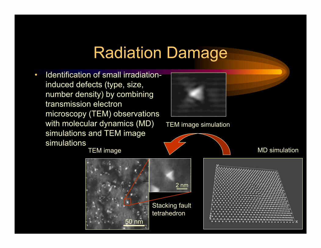
Radiation Damage• Identification of small irradiation-
induced defects (type, size, number density) by combining transmission electron microscopy (TEM) observations with molecular dynamics (MD) simulations and TEM image simulations
TEM image MD simulation
TEM image simulation
50 nm
2 nm
Stacking fault tetrahedron

Radiation Damage Effects
• Molecular dynamics (MD) simulation of the interaction between an edge dislocation (left) flying at 60 m/s and a 2 nm void (centre) in Fe
• (a) dislocation approaching the void• (b) dislocation being attracted to the void• (c) just before the dislocation escapes the void

International Fusion Materials Irradiation Facility IFMIF

Main Functions
• Intense source of 14 MeV neutrons (250 mA)
• Missions:• Qualification of candidate materials up to about full lifetime of
anticipated use in a fusion DEMO reactor• Calibration and validation of data generated from fission reactors
and particle accelerators• Identify possible new phenomena which might occur due to the
high energy neutron exposure

Features
• The neutron spectrum should meet first wall neutron spectrumas near as possible
• Transmutation reaction rates ≅ 10 appm He/dpa, 40 appm H/dpa• Damage rate ≅ 20-50 dpa/year• Range of irradiation temperatures: 300-1000°C• Quasi-continuous operation• Volume of irradiation (high flux test module) = 1/2 liter
• Cost: about 1 billion $ US

Features
40-50~ 450~ 1040-50Hydrogen [appm/dpa]
10-12~ 50~ 110-15Helium [appm/dpa]
20-55~ 10~ 2020-30Damage rate [dpa/year]
IFMIF(High flux module)
Mixed spectrum of high energy protons and spallation
neutrons (SINQ)
Fission neutrons(BOR 60 reactor)
Fusion neutrons(3-4 GW reactor)
Defect poduction(in steels)

Overview
H. Matsui et al., SOFT Conference,
2004

Schematic View
D+ Accelerator
Liquid Li Target
Neutrons(~1017n/s)Li Free
Surface
EMP
D+ Beam (10MW)
Specimens
H. Matsui et al., SOFT Conference,
2004

Test Cell
Medium fluxtest modules
High fluxtest module
Low fluxirradiationtubes
Li Target
Li tank
Shield plug
H. Matsui et al., SOFT Conference,
2004

Small Specimen Test Technology
Specimen type
Present geometry
Comments
Tensile developed
Fatigue developed
Bend/Charpy DFT
Standard achieved;R&D ongoing
Creep Miniaturization needs verification
Crack growth International R&D
ongoing
Fracture toughness
International R&D
ongoing
• On the basis of miniaturized specimens, 0.5 liter (high flux test module) is sufficient to get within 15-20 yearsa representative test matrix up to about 150 dpa for a variety of materials.
1 cm
H. Matsui et al., SOFT Conference,
2004

Broader Approach
• EU-JA Bilateral Agreement to settle the issue of the ITER site:• IFMIF: EVEDA Phase.• NCT: upgrade (JA is contributing to this project also outside BA). • IFERC (International Fusion Energy Research Centre: DEMO
Design R&D Centre, Simulation/Computer Centre, Remote Experimental Centre).
460.00460.00920.00≅700MEuroTotal
172.13110.25282.38IFERC
217.5217.5435.00NCT
70.37132.25202.62IFMIF-EVEDA
JA (500M¥)
EU(500M¥)
Budget(100M¥)
Project
EFDA DATA

EVEDA Phase
• Europe: on the path to fusion power reactors the construction ofIFMIF is of the same importance as the construction of ITER.
• EVEDA Phase:• Optimized EVEDA (Engineering Validation and Engineering
Design Activities) scenario:– Considerable enlargement of the scope of Reference
EVEDA scenario in the aim to reduce the construction risks by performing beam tests with all accelerator components.
• JA could not make a commitment for the construction of IFMIF, but is interested in the optimized EVEDA scenario.
• China has expressed an interest in joining the EVEDA activities.• Other countries are welcome to join.
EFDA DATA

Time Schedule2024202220202018201620142012201020082006
Optimized Scenario
“Fast Track”
European Scenario
Reference Scenario
212019181716151413121110987654321
2024202220202018201620142012201020082006
Optimized Scenario
“Fast Track”
European Scenario
Reference Scenario
212019181716151413121110987654321
EVEDA CODA-2nd Accel.
CODA-1st Accel.
125 mA 250 mADecisions
EVEDA 1st stage Acceler.CODA-2nd Accel.
1st Accel.
125 mA 250 mADecisions
CODA-2nd Accel.125 mA 250 mADecision
ITER schedule
ITER schedule DT PlasmasHH+DD Plasmas
Construction
EVECODA-1st Accel.EVECODA-1st Accel.
EFDA DATA

Conclusion
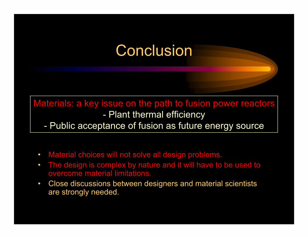
Conclusion
• Material choices will not solve all design problems.• The design is complex by nature and it will have to be used to
overcome material limitations.• Close discussions between designers and material scientists
are strongly needed.
Materials: a key issue on the path to fusion power reactors- Plant thermal efficiency
- Public acceptance of fusion as future energy source