redefine innovative metering protector trip relays ziegler/2012-z-108a-ziegler...262 series panel...
TRANSCRIPT

Protector Trip Relays
ZieglerRedef ine Innovat ive Meter ing
Protector Trip Relays
1
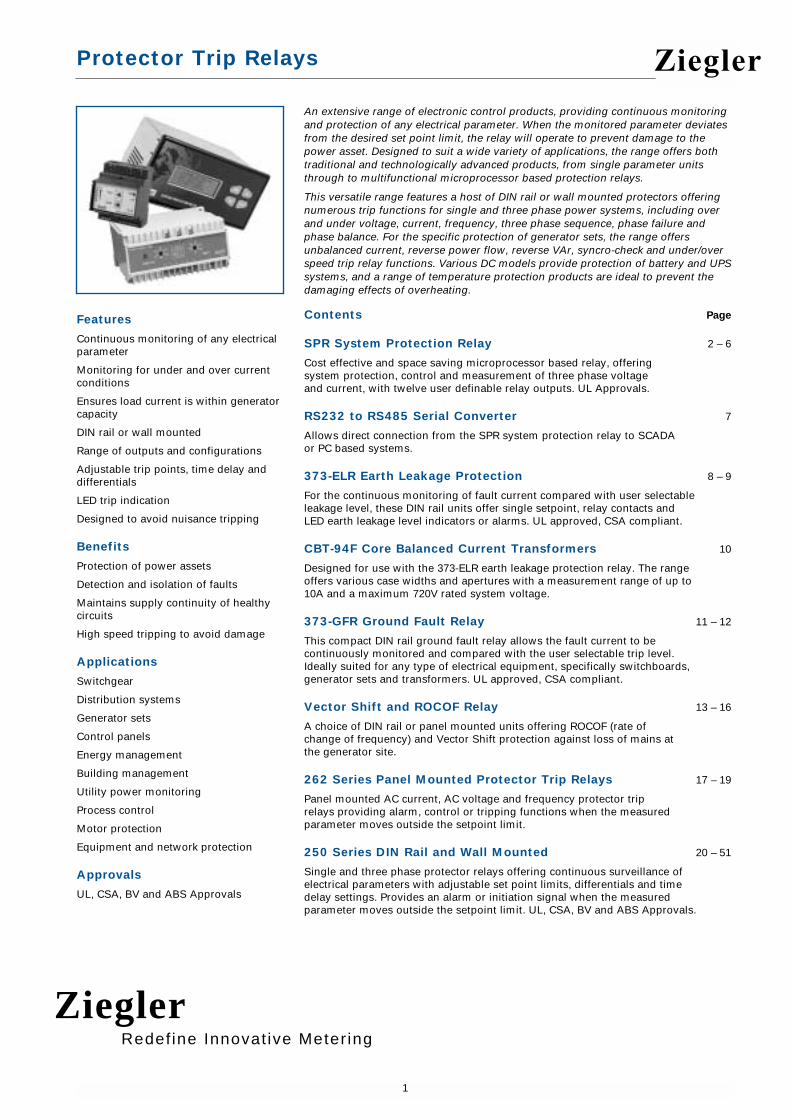
An extensive range of electronic control products, providing continuous monitoringand protection of any electrical parameter. When the monitored parameter deviatesfrom the desired set point limit, the relay will operate to prevent damage to thepower asset. Designed to suit a wide variety of applications, the range offers bothtraditional and technologically advanced products, from single parameter unitsthrough to multifunctional microprocessor based protection relays.
This versatile range features a host of DIN rail or wall mounted protectors offeringnumerous trip functions for single and three phase power systems, including overand under voltage, current, frequency, three phase sequence, phase failure andphase balance. For the specific protection of generator sets, the range offersunbalanced current, reverse power flow, reverse VAr, syncro-check and under/overspeed trip relay functions. Various DC models provide protection of battery and UPSsystems, and a range of temperature protection products are ideal to prevent thedamaging effects of overheating.
Contents Page
SPR System Protection Relay 2 – 6
Cost effective and space saving microprocessor based relay, offeringsystem protection, control and measurement of three phase voltageand current, with twelve user definable relay outputs. UL Approvals.
RS232 to RS485 Serial Converter 7
Allows direct connection from the SPR system protection relay to SCADA or PC based systems.
373-ELR Earth Leakage Protection 8 – 9
For the continuous monitoring of fault current compared with user selectableleakage level, these DIN rail units offer single setpoint, relay contacts andLED earth leakage level indicators or alarms. UL approved, CSA compliant.
CBT-94F Core Balanced Current Transformers 10
Designed for use with the 373-ELR earth leakage protection relay. The rangeoffers various case widths and apertures with a measurement range of up to10A and a maximum 720V rated system voltage.
373-GFR Ground Fault Relay 11 – 12
This compact DIN rail ground fault relay allows the fault current to becontinuously monitored and compared with the user selectable trip level.Ideally suited for any type of electrical equipment, specifically switchboards,generator sets and transformers. UL approved, CSA compliant.
Vector Shift and ROCOF Relay 13 – 16
A choice of DIN rail or panel mounted units offering ROCOF (rate ofchange of frequency) and Vector Shift protection against loss of mains atthe generator site.
262 Series Panel Mounted Protector Trip Relays 17 – 19
Panel mounted AC current, AC voltage and frequency protector triprelays providing alarm, control or tripping functions when the measuredparameter moves outside the setpoint limit.
250 Series DIN Rail and Wall Mounted 20 – 51
Single and three phase protector relays offering continuous surveillance ofelectrical parameters with adjustable set point limits, differentials and timedelay settings. Provides an alarm or initiation signal when the measuredparameter moves outside the setpoint limit. UL, CSA, BV and ABS Approvals.
Features
Continuous monitoring of any electricalparameter
Monitoring for under and over currentconditions
Ensures load current is within generatorcapacity
DIN rail or wall mounted
Range of outputs and configurations
Adjustable trip points, time delay anddifferentials
LED trip indication
Designed to avoid nuisance tripping
Benefits
Protection of power assets
Detection and isolation of faults
Maintains supply continuity of healthycircuits
High speed tripping to avoid damage
Applications
Switchgear
Distribution systems
Generator sets
Control panels
Energy management
Building management
Utility power monitoring
Process control
Motor protection
Equipment and network protection
Approvals
UL, CSA, BV and ABS Approvals
Ziegler
ZieglerRedef ine Innovat ive Meter ing

SPR System Protection, Control and Measurement Relay
2
The SPR system protection relay is a microprocessor based panel mounted deviceoffering protection, control, measurement and communication of up to 37 powerparameters in a single package. The SPR monitors three phases of voltage andcurrent and provides up to twelve user definable relay outputs. The high contrast 80character backlit LCD display allows the user to monitor any of the measuredparameters, inspect setpoint details and relay contact status. The setpoints andconfiguration are all fully programmable via the simple menu driven user interface.Remote monitoring of status information is achievable via the integral RS 485communication port which supports Modbus RTU protocol. SPR is suitable for manydiverse applications, providing cost effective protection of expensive power assets.
Operation
Using an alphanumeric display, the SPR is simple to operate via four buttons whichconfigure and control the product, all parameters can be inspected or modifiedthrough front of panel menu selections. For security, alterations of any parameterscan be disabled with up to four levels of password protection. The default display isthe status screen, where the status of each of the relay contacts can be clearlyidentified, but a user-defined screen can be easily configured to display four lines ofmetering information. SPR can also be remotely monitored and fully controlled overthe RS485 Modbus connection.
Output Relays
The SPR has up to twelve sets of form C change-over (NO+NC) relay contacts, eachrated at 8 Amps 250V AC. These do not have fixed functions, allowing each relay tobe configured to suit a specific application. Flexibility is the key to this product andany function, or combination of functions, can be assigned to any relay. With achoice of up to 18 protective trip functions, and 9 logical functions, SPR provides acost-effective method of protection combined with significant space savings. Ifadditional contact sets are required for any function, programmable logic allows theparallelling of as many additional contacts as are available. The standard product haseight relays, but for the most demanding applications, four additional relays can besupplied as an option. Each relay can be configured to energise or de-energise ontrip (failsafe or non-failsafe operation), latch or self-reset, have its activity recorded inthe event log, or trigger a common alarm, as required.
Watchdog Relay
Following comprehensive self diagnostic checks at power-up, and once correctoperation has been verified, the dedicated change-over (NO+NC) relay contactsenergise to indicate product availability. The microprocessor continuously monitorsthe relay system for healthy operation, and the contacts will de-energise if an internalfault is detected or the auxiliary supply is lost.
Event History Log
Every trip event can be selectively recorded in the history log. Up to 50 events areitemised by date and time stamp to a time resolution of 100ms, ideal for analysingthe sequence of events leading up to a system fault. The internal real time clock hasbattery backup to maintain the correct time and date for many years, even if theproduct is not powered up.
Power Metering
True RMS measurements of up to 37 power measurements are continuouslyupdated. The voltage, current and frequency signals are measured directly, whileother parameters, such as Watts, VAr and VA, are computed from this data. Currentinputs are given a very wide dynamic range in order to process overloads for timeover current functions. Since the readings are true RMS, distorted waveforms areaccurately measured, leading to excellent harmonic performance.
Digital Communications
The built-in RS485 communication port supports Modbus RTU protocol and offersmetering of Phase Voltages, Phase Currents, Watts, VAr, VA, Phase Angle, PowerFactor, Gen and Bus frequency, plus accessibility to all other features and functionsavailable through the front panel. Relay status and system measurements can beinterrogated, and relay parameters can be modified remotely. Remote metering isavailable using Crompton software.
FeaturesIntegrated protection, control,measurement and communication of upto 37 power parameters
Digital communications
Fully programmable VT and CT ratios
Simple menu driven interface
High quality backlit LCD display
True RMS measurement
3 phase, 3 wire or 4 wire unbalancedload options
18 protection relay functions
12 relay contacts outputs
Trip event history log
Watchdog relay
BenefitsReplaces numerous traditionalprotection relays
Significant cost savings
High accuracy
Remote monitoring
Investment protection
Delinquency avoidance
Compact and easy to configure
Time and space saving
ApplicationsG.59/1 Protection
General purpose system protection
Switchgear
Distribution systems
Generator sets
Control panels
Utility power monitoring
Motor protection
Cable protection
Feeder protection
Automatic transfer switches
Railway applications
ApprovalsUL File No. E214283
CSA Compliant
Railtrack Certificate of AcceptancePA05/1450. Scope: Protective Device on Signalling Power Supply Systems
Ziegler

SPR System Protection, Control and Measurement Relay
3
Relay Trip Parameters and Functions
ANSI Description Parameter Range/Resolution/Accuracy
25 Synchronism-Check Phase Difference 2 to 20 degrees / 0.1 degrees / ±1°Monitoring Slip Frequency 0.1 to 1 Hz / 0.01 Hz / ±0.03 Hz of nominal
Voltage Difference 0 to 20% / 0.1 V / ±2% of nominalMinimum Volts Level 5 to 119% / 0.1 V / ±1% of nominal
25D Synchronism-Check Phase Difference 2 to 20 degrees / 0.1 degrees / ±1°monitoring with Dead Slip Frequency 0.1 to 1 Hz / 0.01 Hz / ±0.03 Hz of nominalBus feature Voltage Difference 0 to 20% / 0.1 V / ±2% of nominal
Minimum Volts Level 5 to 119% / 0.1 V / ±1% of nominalDead Bus Voltage 5 to 50% / 0.1 V / ±1% of nominal
27 Under Voltage Relay Voltage Setpoint 5% to 119% V / 0.1 V / ±1% of nominalDiff 1 to 15% V / 0.1 V / ±1% of nominal
32O Directional Active Power Power Setpoint 3 to 120% W / 0.1 W / ±3% of nominal(Forward Watts) Diff 1 to 15% W / 0.1 W / ±1% of nominal
32R Directional Active Power Power Setpoint 3 to 120% W / 0.1 W / ±3% of nominal(Reverse Watts) Diff 1 to 15% W / 0.1 W / ±1% nominal
37 Under Current Relay Current Setpoint 30 to 300% A / 0.01 A / ±2.5% of nominalDiff 1 to 15% A / 0.01 A / ±1% of nominal
40Q Directional Reactive Power Power Setpoint 3 to 120% VArs / 0.1 VArs / ±4% of nominal(Loss of Excitation / Diff 1 to 15% VArs / 0.1 VArs / ±1% of nominalReverse VAr)
46 Unbalanced Current Relay Current Setpoint 5 to 120% A / 0.01 A / ±2.5% of nominalDiff 1 to 15% A / 0.01 A / ±1% of nominal
47 Phase Sequence Relay No Parameters47 Unbalanced Voltage Voltage Setpoint 1 to 25% V / 0.1 V / ±2% of nominal
Relay Diff 1 to 15% V / 0.1 V / ±1% of nominal50 Instantaneous Over Current Setpoint 30 to 300% A / 0.01 A / ±2.5% of nominal
Current Relay Diff 1 to 15% A / 0.01 A / ±1% of nominal50N Instantaneous Neutral Current Setpoint 30 to 300% A / 0.01 A / ±2.5% of nominal
Over Current Relay Diff 1 to 15% A / 0.01 A / ±1% of nominal51 AC Time Over Current Current Setpoint 5 to 120% A / 0.01 A / ±2.5% of nominal
Relay with 3 Time Time Dial 0.1 to 9.9 sec / 0.1 seconds / -Curves Time Curves Standard Inverse, Very Inverse,
Extremely Inverse51V AC Time Over Current Current Setpoint 5 to 120% A / 0.01 A / ±2.5% of nominal
with Voltage Restraint Restraint Voltage 80 to 120% / 0.1 V / ±1% of nominalTime Dial 0.1 to 9.9 sec / 0.1 seconds / -Time Curve Standard Inverse, Very Inverse,
Extremely Inverse51G Neutral Ground Current Setpoint 5 to 120% A / 0.01 A / ±3% of nominal
Fault Relay Time Dial 0.1 to 9.9 sec / 0.1 seconds / -Time Curve Long time standby Earth Fault curve
59 Over Voltage Relay Voltage Setpoint 5 to 120% V / 0.1 V / ±1% of nominalDiff 1 to 15% / 0.1 Volts / ±1% of nominal
81O Over Frequency Relay Frequency Setpoint 40 to 70 Hz / 0.01 Hz / ±0.03 Hz of nominalDiff 0.1 to 10 Hz / 0.01 Hz / ±0.03 Hz of nominal
81U Under Frequency Frequency Setpoint 40 to 70 Hz / 0.01 Hz / ±0.03 Hz of nominalRelay Diff 0.1 to 10 Hz / 0.01 Hz / ±0.03 Hz of nominal
All trip functions feature latching, alarm and invert controls, plus adjustable timedelay 0 to 30 seconds, resolution 0.1 seconds.
In addition to the 18 electrical trip functions, SPR also offers 9 logical functions whichcan be used to create additional trip combinations, selective lockout, or to optimisethe physical relay wiring in the application. Logic functions accept their input signalsfrom the status of up to 3 trip relays. The following functions are available: LogicalAND, OR, NAND, NOR, XOR, Vote, Discrepency, Alarm and Unacknowledged Alarm.
Time Curves
Standard Inverse
Very Inverse
Extremely Inverse
Ziegler
ZieglerRedef ine Innovat ive Meter ing

SPR System Protection, Control and Measurement Relay
4
Specification
Input
Nominal Input Voltage 57.7 to 277V L-N (100 to 480V L-L)Max Continuous Input Voltage 1.2 x NominalMax Short Duration Input Voltage 2 x Nominal (1 second)System VT ratio (primary) Any value up to 400 kVNominal Input Voltage Burden < 0.2 VANominal Input Current 5A (1A option)System CT Ratio (primary) Any value up to 10 kAMax Continuous Input Current 2 x NominalMax Short Duration Input Current 20x Nominal (1 second)Nominal Input Current Burden < 0.6 VAAuxiliary
Nominal Supply Voltage 24V DC (10.6 to 55V DC absolute)Supply Burden < 20 VARS485 Communication
Protocol Modbus RTU, two wire half duplexBaud Rates 2400, 4800, 9600, 19200Parity / Stop Bits Odd, Even, None / 1 or 2Response Time Typical 80ms. Maximum 150msRelay Outputs
Watchdog Relay Outputs 1 User Programmable Relays 8 or 12 Relay Contact Type Volts-free change-over (form C) Relay Contact Rating 8 Amp (resistive) 250V ACRelay Make Current 30 Amp (4 sec @ <10% duty cycle)Rated Breaking Capacity 2000 VARelay Mechanical Life 30 Million Operations Relay Contact Life B300/120V AC/70°C to UL508
B300/240V AC/70°C to UL508Measuring Ranges
Voltage 20 .. 120% of nominal Current 20 .. 120% of nominal (functional 5 .. 500%)Frequency 45 .. 66 HzPower Factor 0.5 .. 1 .. 0.5 Importing or ExportingWatts 5 .. 120%Enclosure
IP Rating IP54 with panel gasket (supplied)Material Zinc passivated steel with polycarbonate
front panelTerminals Removable shrouded screw clamp terminalsOperating Temperature 0°C to +50°C (Optional -20°C to +60°C)Storage Temperature -20°C to +70°CRelative Humidity 95% non-condensingShock 30g in 3 planesVibration 10 to 150 Hz, @ 1g amplitudeDimensions 200mm (7.87") wide, 106mm (4.17") high,
176mm (6.93") deep. Panel Cut Out 187mm wide (7.36") x 93mm (3.66") highWeight < 3 kgCompliant With G.59/1, BS EN 50081-1, BS EN 50082-2,
BS EN 61010-1, BS EN 60255-4,BS EN 60255-6, ANSI/IEEE C37.90 UL508, UL and CSA File No: E214283
Railtrack Certificate of Acceptance PA05/1450 Protective Device on SignallingPower Supply Systems
Measurement, Display andCommunication
SPR offers configuration, display andcommunication of up to 37 true RMSpower measurements
Voltage L1-L2Voltage L2-L3Voltage L3-L1 Voltage L1-N Voltage L2-NVoltage L3-NSystem Voltage (average)
Current L1 Current L2Current L3System Current (average)System Current (sum)Neutral Current Ground Current
System WattsWatts L1Watts L2Watts L3
System VArVAr L1VAr L2VAr L3
System VA VA L1VA L2VA L3
Power FactorPF L1PF L2PF L3
Phase AnglePA L1PA L2PA L3
Gen Frequency
Bus Frequency
Gen-Bus Angle
Ziegler
ZieglerRedef ine Innovat ive Meter ing

SPR System Protection, Control and Measurement Relay
5
SPR-SOFT Communication and Programming Software
The software configuration package allows the user to configure and monitor theoperation of the SPR system protection relay through a Windows style user interface.It allows the user to load and save the configuration to and from a hard disk on a PC,and to send and retrieve configuration settings to and from up to 31 SPR units.Communication is achieved with a Modbus connection to a COM port on the PC via anRS485/RS232 converter.
The software configurator is designed to display and set up the parameters of theSPR relays, to monitor the status of the selected SPR, and to provide status of thepower supplies the SPR is monitoring. A separate configuration page is provided forsetting the parameters of each relay.
The configurator incorporates separate pages to display measurements, relays andevent data. When one of these pages is selected in on-line mode, the configuratorinterrogates the selected SPR every few seconds to obtain the data required for thatpage. In addition, there is an option to bring up the measurements page from anyother page if the SPR raises an alarm.
Product Codes
Product Code Product Configuration
SPR-013W-*LS-**-BD-***-MB SPR 3 phase 3 wire, 5A, 24V DC auxiliary power with RS485 Modbus
Input Voltage*
PK 100 Volts L-LPM 110 Volts L-LPO 115 Volts L-LPQ 120 Volts L-LRM 208 Volts L-LRU 380 Volts L-LRW 400 Volts L-LSB 415 Volts L-LSH 440 Volts L-LSE 480 Volts L-L
Product Code Product Configuration
SPR-014W-*LS-**-BD-***-MB SPR 3 phase 4 wire, 5A, 24V DC auxiliary power with RS485 Modbus
Input Voltage*
NV 57.7 Volts L-NNX 63.5 Volts L-NPA 69.0 Volts L-NPK 100 Volts L-NPM 110 Volts L-NPQ 120 Volts L-NP7 127 Volts L-NR4 220 Volts L-NRQ 230 Volts L-NRR 240 Volts L-NRS 250 Volts L-NR6 277 Volts L-N
Frequency**
C5 50HzC6 60HzRelays***
08 8 x relays12 12 x relays
Optional Accessories
SPR-POWER-A1 Auxiliary Power Supply Unit 85-264V AC & 100-375V DC
SPR - SOFT Communication and Programming Software9D-485 RS232 to RS485 Serial Converter
Order Code Example:
SPR-013W-PQLS-C5-BD-12-MB
SPR 3 phase 3 wire, 120V L-L, 5A, 50Hz,24V DC auxiliary power with RS485Modbus, 12 relays
Ziegler
ZieglerRedef ine Innovat ive Meter ing

SPR System Protection, Control and Measurement Relay
6
Connections
The four current transformer inputs are fully isolated from ground and from eachother, allowing the SPR to be used as an intermediate device or connected to acommon ground as required. All electrical connections are made using two-partremovable connecting blocks.
SPR-013W SPR-014W
3-Phase 3-Wire Unbalanced Load 3-Phase 4-Wire Unbalanced Load
Auxiliary Supply
Designed to operate from 24V D.C. nominal engine batteries, operating normally atreduced voltage when the engine is cranking, and increased voltage when thebatteries are on charge. The switched mode auxiliary power supply has a very wideoperating range of 10.6 to 55 volts. A separate auxiliary module is available for otherauxiliary voltages.
Safety / Ground Connections
The ground stud on the rear panel should be connected to a clean ground. For safetyreasons, CT secondary connections should be grounded according to appropriatecodes of practice.
SPR-POWER Switched Mode Power Supply
The SPR is designed to operate with a nominal 24 volt DC auxiliary supply, however,the SPR-POWER unit will derive a suitable supply for applications utilising 85 to 264VAC, 45-66 Hz or 100 to 375V DC. This switched mode power supply is simplyattached to the System Protection Relay (SPR) chassis via two threaded screws.
Input
Input Voltage 85 to 264V AC, 45-66 Hz 100 to 375V DCBurden < 36 VAOutput
Output Voltage 24 volts DC @ 600mA Environmental
Operating Temperature -20 to +50°CStorage Temperature -30 to +80°CRelative Humidity 0 .. 95% non condensingEnclosure
Style Custom design to mount directly on SPRMaterial Zinc passivated steelTerminals Barrier terminal strip 6-32 binding head screwGrounding Dedicated grounding stud provided
SPR Dimensions
Front Display Area
Side View
Panel Cutout
Dimensions with Optional SPR-POWER Unit
185.0mm (7.28")
89.5mm(3.52")
188.5mm(7.42")
53mm(2.09")
SPR-Power Unit
SPR Assembly
Ziegler
ZieglerRedef ine Innovat ive Meter ing

RS232 to RS485 Serial Converter
7
The SPR system protection relay features an integral RS485 communication port,allowing direct connection to SCADA systems via Modbus RTU protocol. However,the SCADA systems or PC based equipment used for remote monitoring of electricaland power parameters often incorporate RS232 communication ports, thereforeconversion to RS485 is necessary. The 9D-485 module is a simple non-isolated twowire half duplex RS485 converter which fits into any PC based system.
This port powered two-channel module converts the TD and RD RS232 lines tobalanced half-duplex RS485 signals via a 9 way female D type connector on theRS232 side, and a screw clamp terminal block connector on the RS485 side. Themodule has an internal connection to prevent data transmitted from the RS232 portfrom being echoed back to the RS232 port.
Operation
The 9D-485 module is powered from two RS232 output handshake lines. However,an external 12V DC power supply can be connected to two terminals on the RS485connector if no handshake lines are available. When using an external supply, thesupply should be connected only to specifically labeled power inputs (power jack,terminal block, etc.).
Note: Connecting an external power supply to the handshake lines may damage the unit.
Although the 9D-485 module uses handshake lines to power the converter, nohandshaking is required to control the RS485 driver. The RS485 driver isautomatically enabled during each spacing state on the RS232 side. During themarking or idle state, the RS485 driver is disabled and the data lines are held in themarking state by pull-up and pull-down resistors.
Specification
Protocols Supported Modbus RTUInternal Power 2 x RS232 handshake lines External Power 12V DC to RS485 side if handshake lines
unavailableCurrent Draw 35mA max when externally poweredRS232 Connector 9 way female D TypeRS232 Signals Passes through pins 3 (TD) and 2 (RD)
Pins 7 (RTS) and 8 (CTS) are tied togetherPins 4 (DTR), 6 (DSR), and 1 (CD) are tied together
RS485 Connector Screw clamp terminal blockRS485 Signals Automatic control circuit enables driver only
when transmittingRS485 Receiver Disabled when transmitting to prevent echo
back to RS232 RS485 Communications Half duplex two wire operationRS485 Baud Rate Up to 115.2k baudMaximum Distance Up to 1200 meters (4000 feet)Multidrop Connections Up to 32Compliant With EN 55022, EN 61000-6-1, EN 61000-4-2,
EN 61000-4-3, EN 61000-4-4, EN 61000-4-5, EN 61000-4-6, EN 61000-4-8, EN 61000-4-11
Dimensions 89mm long x 34mm wide x 17mm deep3.50" long x 1.34" wide x 0.67" deep
Product Code
9D-485 Port powered RS232 to RS485 serial converter
Features
Direct connection to PC RS232 serial port
9 way female D type connector
Port powered or externally powered
Balanced RS485 signals
Very high noise immunity
Two wire half duplex
Prevents echo-back to RS232
Compatible With
SPR System Protection Relay
Applications
PC based communication systems
SCADA Systems
PLC interfacing
Energy management systems
Ziegler
ZieglerRedef ine Innovat ive Meter ing

373-ELR Earth Leakage Protection Relay
8
Residual current devices are used to detect potentially dangerous earth fault currentsbefore damage is caused. An undetected fault current may lead to cablesoverheating, which could start a fire. If high fault currents are involved, hazardousvoltages may also appear on earthed equipment, putting lives at risk. The 373-ELRearth leakage protection relay allows the fault current to be continuously monitoredand compared with the user selectable leakage level. Should the leakage exceed thislevel, the relay will trip to indicate a fault condition. With a very fast response time ofunder 40ms, the supply can be disconnected before serious damage can occur. Thisproduct is intended to provide a high degree of earth leakage protection andmonitoring for any electrical equipment, specifically motors and their control gear,generator sets and transformers.
Description
The 373-ELR range offers a standard DPCO version, incorporating a single setpoint,LED leakage level indicator and double pole change over relay contacts. The defaultrelay operation is to de-energise on trip, however, relay operation can be reversed toenergise on trip by fitting a wire link between two terminals. For additionalfunctionality, an optional pre-alarm relay version is available where the main setpointrelay has two single pole change over contacts, one of which will de-energise on tripfunction and the other will de-energise when the leakage level reaches 60% of theselected setting.
This protector does not check the continuity of any part of the earthing circuit, it isdesigned for secondary protection due to the externally connected currenttransformer and contactor components. Life protection devices require an integral CTand main contactor.
Operation
The 373-ELR features two incremental rotary selector switches on the front panel anda series of LED annunciators. The 10 position trip current switch offers selectableearth leakage current settings from 30mA to 10 Amps, and the 16 position time delaysetpoint switch offers additional delay for fault discrimination, selectable from 0 to 10seconds. When the 30mA trip current leakage is selected, the time delay is disabled.Once the trip current and time delay selections have been made, a green LEDprovides indication of mains healthy supply. The red LED will automaticallyilluminate if the pre-set leakage level has been exceeded, after any selected timedelay.
The unit also incorporates a bargraph of 5 yellow LEDs providing indication of thelevel of leakage in 20% increments. When all 5 LEDs are illuminated the leakage levelhas reached 100% of the setpoint setting. The enhanced pre-alarm single polechange over relay contact version also incorporates a red LED providing indicationthat the level of leakage has reached 60% of the selected range, and that the pre-alarm relay has operated.
The unit features a combined reset and test button. A short press of the button willreset the unit after a trip, and one long press initiates an electronic confidence check.The relay latches on to a fault until the test/rest button is pressed or the auxiliarypower is removed. The relay will de-energise on trip (fail safe) as standard. Fitting alink between two terminals will select energise on trip.
Analogue Outputs
The 373-ELR unit incorporates an 0/1mA analogue output which equals 0 to 100% ofthe selected tripping level. It can be used to drive an external test meter or panelmeter, thus providing measurements for test commissioning and a useful indicationof potential problems. The analogue output also enables fault level diagnosis to becommunicated into building management or intelligent SCADA systems, wherebyinsulation deterioration can be monitored over a period of time and preventativemaintenance arrangements made prior to expensive equipment failure.
Core Balanced Current Transformers
The leakage current is determined by passing the phase conductors (and neutral ifpresent) through a core balanced current transformer, all supply cables must passthrough the same aperture. The current transformers sum the currents flowing intoand back from the load. Ideally, the load will have no leakage current, so current flowthrough the CT will completely cancel out. For example, 100 Amps flowing into loadand 97 Amps flowing back provides an output of 3 Amps. Crompton offer a full rangeof core balanced current transformers suitable for use with 373-ELR earth leakageprotection relays.
Features
Precision digital settings
LED bargraph display
10 selectable trip levels – 30mA to 10A
16 selectable time delay – 0msto 10 seconds
Less than 40ms response time
0-1mA analogue output
8 Amp 250V rated relay contacts
User selectable energise or de-energiselink
Double pole change over relay
Single pole pre-alarm option
Benefits
DIN rail 43880 enclosure
Switched mode supply accepts a widerange of auxiliary voltages
Detects residual current flow
Isolation of faulty circuits
Insulation monitoring
Advanced warning of faults
Complementary range of core balanced CTs
Protection of expensive power assets
Applications
Switchgear
Distribution systems
Generator sets
Control panels
Building management
Utility power monitoring
Process control
Motor protection
Transformer protection
Approvals
UL 3111-1 File No: E203000
CSA compliant
EMC and LVD
Ziegler
ZieglerRedef ine Innovat ive Meter ing

373-ELR Earth Leakage Protection Relay
9
Dimensions to DIN 43880
Connections
Specification
Measuring Input From core balanced current transformerOverload 20 x nominal for 1 secondFrequency 50Hz or 60Hz ±10%Auxiliary Voltage 12 - 48V D.C. , 24 - 48V A.C & D.C.or
100 - 250V A.C.& D.C.Auxiliary Burden Less than 1.5 WattsTrip Current Settings Selectable 30mA, 100mA, 200mA, 300mA,
500mA, 1A, 2A, 3A, 5A, 10ATrip Accuracy 50% < trip point current
<100% in accordance with IEC 1543Trip Response Time < 40ms (at 5 x rated trip current, ignoring the
selected time delay)Time Delay Setpoints Selectable 0ms, 50ms, 100ms, 150ms, 200ms,
300ms, 400ms, 500ms, 600ms, 700ms, 800ms, 900ms, 1 second, 2 seconds, 5 seconds, 10 seconds. When 30mA leakage is selected, the time delay is disabled
Indication 5 yellow LED bargraph for leakage levelsRed LED indicated trip functionGreen LED indicated auxiliary power presenceRed LED pre-alarm indication (SPCO version only)
Relay Contacts Standard: Double pole change overOption: 2 single pole change over (pre alarm and main alarm)
Relay Contact Rating 8 Amps at 250V A.C.8 Amps at 30V D.C. resistive
Relay Mechanical Life > 100,000 operationsAnalogue Output 0 to 1 mA = 0 to 100% of selected tripping level.
Compliance 1V, accuracy 10%Enclosure Style DIN 43880, rail width 70mmCompliant With EMC and LVD, UL 3111-1 File No: E203000,
CSA 22.2/1010.1-92 BSEN 50081-1, BSEN 50082-2,IEC 60255-22-1 (BS5992), IEC 60255-11, BSEN 61543 (IEC 1543), BSEN 61010 (IEC 1010), EN 60068 (IEC 68)
Material Flame retardant UL94V0Terminals 1 to 4 mm2 solid or stranded conductors.
IP20 protectionOperating Temperature -10 to +60°CStorage Temperature -20 to +70°CRelative Humidity 0 .. 95% non condensingWeight <250gDimensions 71mm wide x 90.5mm high x 73mm deep
2.79" wide x 3.56" high x 2.87" deep
Product Codes – Double Pole Change Over Relay
Frequency Auxiliary Supply Catalogue No.
50Hz 12-48V DC 373-ELRW-CBC5-A1-ST50Hz 24-48V AC & DC 373-ELRW-CBC5-A2-ST50Hz 100-250V AC & DC 373-ELRW-CBC5-A3-ST60Hz 12-48V DC 373-ELRW-CBC6-A1-ST60Hz 24-48V AC & DC 373-ELRW-CBC6-A2-ST60Hz 100-250V AC & DC 373-ELRW-CBC6-A3-ST
Product Codes – Pre-Alarm Single Pole Change Over Relay
Frequency Auxiliary Supply Catalogue No.
50Hz 12-48V DC 373-ELRW-CBC5-A1-PA50Hz 24-48V AC & DC 373-ELRW-CBC5-A2-PA50Hz 100-250V AC & DC 373-ELRW-CBC5-A3-PA60Hz 12-48V DC 373-ELRW-CBC6-A1-PA60Hz 24-48V AC & DC 373-ELRW-CBC6-A2-PA60Hz 100-250V AC & DC 373-ELRW-CBC6-A3-PA
110.0mm 4.32"
73.0mm 2.87"
33.0mm 1.3"
48.0mm 1.89"
71.0mm2.79"
62.5
mm
2.46
"
90.5
mm
3.56
"
46.0
mm
1.87
"
Remoteresetswitch
FusedAuxiliarysupply
The equipment groundingconductor must bypass the CT
CommissioningMeter
Link to energiseon trip
GND
Relay 1 Relay 2
Ziegler

CBT-94F Core Balanced Current Transformers
10
The CBT-94F series of core balanced current transformers are exclusively for usewith our 373-ELR earth leakage protection relay. The extremely sensitive toroidalcore and secondary winding are encapsulated by a self extinguishing case providingexcellent mechanical strength, protection from damage, and electrical insulation.
Description
Residual current devices are used to detect potentially dangerous earth fault currentsbefore damage is caused. An undetected fault current may lead to cables overheating,which could start a fire. If high fault currents are involved, hazardous voltages mayalso appear on earthed equipment, putting lives at risk. An earth leakage protectionrelay is intended to provide a high degree of protection and monitoring for anyelectrical equipment, specifically motors and their control gear, generator sets andtransformers. The leakage current is determined by passing the phase conductors(and neutral if present) through a core balanced current transformer.
Operation
Primary conductors should be grouped together and fed through the currenttransformer aperture. It is essential that each conductor passes through the device inthe same direction. Each phase conductor (and neutral if present) must pass throughthe current transformer. The current transformers sum the currents flowing into andback from the load. Ideally, the load will have no leakage current, so current flowthrough the CT will completely cancel out. For example, 100 Amps flowing into loadand 97 Amps flowing back provides an output of 3 Amps.
The equipment grounding conductor must always bypass the current transformer.The connections between the current transformer and protector should be kept asshort as possible to minimise signal noise. For best results, use screened cable, withthe screen grounded at the protector.
Specification
System Voltage 720V maximumTest Voltage 3kV AC for 1 minuteSystem Frequency 50Hz or 60HzPrimary Ratings From 30mA to 10ASecondary Terminals Protected to IP20Operating Temperature –10° C to +50° CEnclosure UL94V0 flame retardant plasticCompliant With IEC185, VDE 0414Mounting Hardware Steel mounting feet for wall or base mounting
Product Codes and Dimensions
Aperture
Dim E Dim A Dim B Dim C Dim D Catalogue No.
35mm 100mm 79mm 26mm 48.5mm CBT-94F-03570mm 130mm 110mm 32mm 66mm CBT-94F-070105mm 170mm 146mm 38mm 94mm CBT-94F-105140mm 220mm 196mm 49mm 123mm CBT-94F-140210mm 299mm 284mm 69mm 161mm CBT-94F-210300mm 400mm 380mm – – CBT-94F-300
Features
Leakage measurement range 0-10 Amps
6 models available
Integral wire sealable terminal cover
Flame retardant high impact mouldedcase
Benefits
Reduction of high currents for ease ofmetering
Wide operating temperature –10° C to+50° C
Steel mounting feet supplied
Long product life
Applications
Switchgear
Distribution systems
Generator sets
Control panels
Motor protection
Transformer protection
Overload protection
Approvals
IEC 185
VDE 0414
A
øE
B
33
DC
46
Ziegler
ZieglerRedef ine Innovat ive Meter ing

373-GFR Ground Fault Relay
11
The 373-GFR is designed to detect dangerous ground fault currents before damage iscaused to expensive power assets. An undetected fault current may lead to cablesoverheating, which could start a fire. If high fault currents are involved, hazardousvoltages may also appear on grounded equipment, putting lives at risk. The 373-GFRground fault relay allows the fault current to be continuously monitored andcompared with the user selectable trip level. Should the fault exceed this level, therelay will trip to indicate a fault condition. With a very fast response time of under40ms, the supply can be disconnected before serious damage can occur. Thisproduct is intended to provide a high degree of ground fault protection andmonitoring for any type of electrical equipment, specifically switchboards, generatorsets and transformers.
Operation
The 373-GFR offers a single pole change over relay contact incorporating a singlesetpoint, which will de-energise on trip. The relay senses the ground current bymeasuring the voltage developed across the N-G link impedance under a faultcondition. Link selection of two standard N-G impedances, 0.2mΩ or 2mΩ. This is avery cost effective method, since a current transformer is not required.
The 373-GFR features two incremental rotary selector switches on the front paneland a series of LED annunciators. The 10 position trip current switch offers selectableground fault current settings from 100 to 1200 Amps, and the 16 position time delaysetpoint switch offers additional delay for fault discrimination, selectable from 0 to 10seconds.
Once the trip current and time delay selections have been made, a green LEDprovides indication of mains healthy supply. The red LED will automaticallyilluminate if the pre-set fault level has been exceeded, after any selected time delay.The unit also incorporates a bargraph of 5 yellow LEDs providing indication of thelevel of fault in 20% increments. When all 5 LEDs are illuminated the fault level hasreached 100% of the setpoint setting.
The unit features a combined reset and test button. A short press of the button willreset the unit after a trip, and one long press initiates an electronic confidence check.The relay latches on to a fault until the test/rest button is pressed or the auxiliarypower is removed. However, automatic reset can be achieved by fitting a wirebetween two terminals. The relay will de-energise on trip (fail safe) as standard.
Analogue Outputs
The 373-GFR unit incorporates an 0/1mA analogue output which equals 0 to 100% ofthe selected tripping level. It can be used to drive an external test meter or panelmeter, thus providing measurements for test commissioning and a useful indicationof potential problems. The analogue output also enables fault level diagnosis to becommunicated into building management or intelligent SCADA systems, wherebyinsulation deterioration can be monitored over a period of time and preventativemaintenance arrangements made prior to expensive equipment failure.
Product Codes – Single Pole Change Over Relay
Frequency Auxiliary Supply Catalogue No.
50Hz 12-48V DC 373-GFRW-SHC5-A1-SP50Hz 24-48V AC/DC 373-GFRW-SHC5-A2-SP50Hz 100-250V AC/DC 373-GFRW-SHC5-A3-SP60Hz 12-48V DC 373-GFRW-SHC6-A1-SP60Hz 24-48V AC/DC 373-GFRW-SHC6-A2-SP60Hz 100-250V AC/DC 373-GFRW-SHC6-A3-SP
Features
Precision digital settings
LED bargraph display
10 selectable trip levels – 100 to 1200Amps
16 selectable time delay – 0ms to 10 seconds
Less than 40ms response time
0-1mA analogue output
User selectable input range of 0.2mΩor 2mΩ
User selectable latching/self-resetting
Single pole change over relay
8 Amp 250V rated relay contacts
Benefits
DIN rail 43880 enclosure
Switched mode supply accepts a widerange of auxiliary voltages
Isolation of faulty circuits
Insulation monitoring
Advanced warning of faults
Protection of expensive power assets
Current transformer not required
Applications
Switchgear
Distribution systems
Generator sets
Control panels
Utility power monitoring
Transformer protection
Approvals
UL 3111-1 File No: E203000
CSA compliant
EMC and LVD
Ziegler
ZieglerRedef ine Innovat ive Meter ing

373-GFR Ground Fault Relay
12
Specification
Measuring Input A.C. voltage developed across N-G linkMeasuring Range 0.2Ω or 2Ω shunt impedance link selectableOverload Maximum input voltage 600VFrequency 50/60HzAuxiliary Voltage 12 - 48V D.C. , 24 - 48V A.C & D.C.or
100 - 250V A.C.& D.C.Auxiliary Burden Less than 1.5 WattsTrip Current Settings Selectable 100A, 150A, 200A, 250A, 300A, 450A,
600A, 750A, 800A, 1200ATrip Accuracy 50% < trip point current ≤100% in accordance
with IEC 1543Trip Response Time < 40ms (at 5 x rated trip current, ignoring the
selected time delay)Time Delay Setpoints Selectable 0ms, 50ms, 100ms, 150ms, 200ms,
300ms, 400ms, 500ms, 600ms, 700ms, 800ms, 900ms. 1 second, 2 seconds, 5 seconds, 10 seconds.
Indication 5 yellow LED bargraph for fault levelsRed LED indicated trip functionGreen LED indicated auxiliary power presence
Relay Contacts Single pole change over (SPCO or NO+NC) contactsRelay Contact Rating 8 Amps at 250V A.C.
8 Amps at 30V D.C. resistiveRelay Mechanical Life > 100,000 operationsAnalogue Output 0 to 1 mA = 0 to 100% of selected tripping level.
Compliance 1V, accuracy 10%Enclosure Style DIN 43880, rail width 70mmCompliant With EMC and LVD, UL 3111-1 File No: E203000,
CSA 22.2/1010.1-92, BSEN 50081-1, BSEN 50082-2, IEC 60255-22-1 (BS5992), IEC 60255-11, BSEN 61543 (IEC 1543), BSEN 61010 (IEC 1010), EN 60068 (IEC 68)
Material Flame retardant UL94V0Terminals 1 to 4 mm2 solid or stranded conductors.
IP20 protectionOperating Temperature -10 to +60°CStorage Temperature -20 to +70°CRelative Humidity 0 .. 95% non condensingWeight <250gDimensions 71mm wide x 90.5mm high x 73mm deep
2.79" wide x 3.56" high x 2.87" deep
Connections
Install the neutral to ground shunt resistor in a suitable location. Connect the shuntsense wires directly to terminals N (neutral side) and G (ground side) on the relay.Cabling between the shunt resistor and the ground fault relay should be kept to a minimum.
Dimensions to DIN 43880
Terminal No.
N Neutral inputG Ground input13 Fused auxiliary supply (-)14 Fused auxiliary supply (+)15 Default operation is
non-latching16 Fit link to enable relay
latch on trip
17/18 Analogue output 0/1 mA19 Default input range is for
2mΩ shunt20 Link to select 200µΩ shunt
input25 Relay (NO)24 Relay (COM)23 Relay (NC)
NORMAL
CLOSED
COM
OPEN
TRIP
OPEN
COM
CLOSED
LINK FORLATCHING RELAY
ANALOGUEOUTPUT
LINK FOR200µ SHUNT
+_
23
24
25
15
16
17
18
19
20
14
13
NG
+_
SIG
NA
LA
UX
110.0mm (4.32")
73.0mm (2.87")
33.0mm (1.3")
48.0mm (1.89")
71.0mm (2.79")
62.5
mm
(2.
46")
90.5
mm
(3.
56")
46.0
mm
(1.8
7")
Ziegler
ZieglerRedef ine Innovat ive Meter ing

Vector Shift and ROCOF Relay
13
The Vector Shift and ROCOF protection relay is designed for applications where agenerator is running parallel with a mains supply either from a utility or othergenerators. The relay will detect disconnection of a generator from the network,(islanding of an embedded generator) and trip the generator’s circuit breaker. It isspecifically designed to protect the mains from the potential damaging effects ofreconnection whilst out of synchronism, and the supply of power to local lineswithout authority. The relay is available in two case styles, both of whichsimultaneously sense Vector shift and a Rate Of Change Of Frequency (R.O.C.O.F) asmeasurement parameters in compliance with G.59/1 and ETR 13. For optimum safetyeach generator should have its own Vector Shift and ROCOF protection relay.
Description
The Vector Shift and ROCOF relays provide continuous simultaneous supervision ofvector shift and rate of change of frequency functions. The relay monitors powerquality and disconnections, allowing fast, reliable and accurate mains failuredetection to protect the network, load and the generator. This highly innovative relaycan additionally be used to measure the actual conditions at the generator site, thusfacilitating the setting of the correct trip point, trip logging, and the provision ofsimple and reliable commissioning.
Vector Shift Relay
The Vector Shift relay measures the length of each cycle of the voltage wave. At themoment a genset becomes disconnected, the sudden change in load causes asudden change in cycle length. The single cycle becomes shifted with time: it takeslonger or shorter. The speed of sensing is fast enough to complete the opening ofthe genset main circuit breaker before the auto recloser completes reclosing. Hencethe Vector Shift relay is an excellent method of detecting disconnection from the grid.
ROCOF Relay
The R.O.C.O.F. relay senses stability of the frequency. A genset in routine operationwill have a normal frequency excursion due to changing loads and the compensatedfuel inlet. These frequency excursions are small. The rate at which the frequencychanges inside these excursions is relatively high compared with those of a largenetwork. The speed of sensing is fast enough to complete the opening of the gensetmain circuit breaker before the auto reclosers complete reclosing. Hence a R.O.C.O.F.relay adjacent to the genset is also an excellent method of detecting disconnectionfrom the grid.
Operation
Health Monitoring
The unit incorporates additional circuitry to continuously monitor its own operation.This is essential to maintain confidence in the protection system itself. It monitorsconditions such as correct software execution, correct voltages within the hardwareand functionality of the microprocessor core. If any faults are detected the unit willindicate an error condition and restart.
Dependability
The relay uses sophisticated change detection algorithms to avoid spurious trips.These can occur during normal grid switching. The Vector Shift algorithm includes aunique routine which analyses the cycles immediately before and after a possibleevent. This results in a response only to a true phase step or Vector Shift condition.To allow for a step change of up to 20% of rated load, a limit setting of 16 electricaldegrees is typical. This can be reduced to 6 electrical degrees on low impedancenetworks, but is user selectable between 2 and 24 electrical degrees.
Features
Compliant with utility industryrequirements
Unique alogorithm
Continuous self supervision
Controlled power up/down
Status and fault indication
PC logging and indicating software
Digital data and status output
External input for “holding off”
Internal self check functions
Change over relay contacts
User selectable settings
Benefits
Fast, reliable and accurate mains failuredetection
Power quality and disconnectionmonitoring
Protection of grid, load and generator
DIN rail or panel front mounted options
Vector shift and ROCOF functionshoused in one unit
Improved discrimination
Nuisance tripping avoidance
Simple installation and operation
Applications
G.59/1 protection
Generator sets
Co-generation
Uninterruptible power supplies (UPS)
Base load
Peak lopping
Combined heat and power (CHP)
Utility power monitoring
Compliant With
G.59/1, ETR 113
EMC, LVD and safety standards
Ziegler
ZieglerRedef ine Innovat ive Meter ing

Vector Shift and ROCOF Relay
14
Dual Functionality
The unit performs two distinct operations from the same basic information. The zerocrossover points of the voltage waveform are monitored to establish the runningaverage system frequency. This information then forms a reference for the twomonitored parameters:
a) Vector Shift: This algorithm responds to a single cycle of incorrect duration, as caused by a Vector Shift, and will qualify this by monitoring the next cycle. If the Vector Shift is not qualified the “near trip” LED is illuminated and no further action is taken. The response time for this operation is typically 40 ms in a 50 Hz system.
b) Rate of Change of Frequency (R.O.C.O.F): The second algorithm performs a continuous comparison of the instantaneous frequency and the running average system frequency. This equates to the rate at which the generator is changing speed.
Output Latching
The alarm signal from either of the algorithms will cause the trip relay contacts toclose. Should the out of range conditions return to normal, the relay will remain inthe alarm state until the unit is manually or remotely reset. The control system cantherefore be configured to ensure that the normal synchronisation procedure isfollowed before the generator is reconnected.
ROC-SOFT Trip Logging and Indicating Software
ROC-SOFT software functions as a simple meter and logger, and is available free onrequest. It enables three functions:
1. It becomes an effective R.O.C.O.F. meter and Vector Shift meter.
2. It enables the setting of the trip point, justified by actual site measurements.
• Running the generator (optionally with site load) whilst islanded, the R.O.C.O.F. value will be displayed. R.O.C.O.F. is caused by the generators own control dynamics and by the demands from load changes.
• Running the generator (optionally with site load) during a disconnection from thegrid at a trip setting of 2°, the Vector Shift value will be displayed on tripping. Vector Shift is caused by a change in current, which will also cause a R.O.C.O.F.
The values obtained by measurement form a justified basis for setting the trip levels.
3. It is a simple trip logger, as every trip is logged, date and time stamped, and nature of trip. The following values are displayed:
• Vector Shift trip levels set
• Vector Shift trip level actual measured on trip
• R.O.C.O.F. trip level set
• R.O.C.O.F. trip level actual measured on trip
• R.O.C.O.F. level actual measured at present.
As the measurements are so much faster than is practical to display, the display isupdated once per second with the value at that time. Full data is available from theopto data socket, please see the User Manual. To print a log, press Alt and PrintScreen on the PC keyboard. Then in Word select the clipboard contents and print.
Optical to RS232 Serial Converter
The Vector Shift and R.O.C.O.F. relay can be used in conjunction with our optical todigital adaptor, which converts optical fibre to RS232 digital signal levels for use witha PC. Crompton offer a 25 way or 9 way D socket adaptor to suit the PC, and apolymer fibre-optic cable to ensure the avoidance of electrical interference.
Ziegler
ZieglerRedef ine Innovat ive Meter ing

Vector Shift and ROCOF Relay
15
Specification
Input Supply 110, 120, 220, 230, 240, 380, 400, 415VInput Range -50%, +50%Frequency 40 to 70 HzHarmonics The monitored waveform must be free from
harmonic oscillations near the zero crossover pointsBurden Input: 0.1VA Auxiliary: 4VAVoltage Withstand (overload) +50% continuousOutput Volt free relay contactsRelays 1x status, 1x faultContacts Single pole changeoverRating 250V, 5A A.C., resistiveOperations 0.2 millionBaud Rates 9600, 8 bit data, 1 stop bit. No parityAuxiliary Supply 110, 120, 220, 230, 240, 380, 400, 415VAuxiliary Range ±20%Setting Accuracy Vector Shift better than 1° R.O.C.O.F 0.05 Hz/sResponse Time Phase angle shift: up to 2 cycles +5ms relay time
Frequency rate change: 3 to 32 cycles + 5ms relay time
Isolation BS 142, Section 1.3Delay Range 0.1sPhase Angle Shift 0.5 degree at 50/60 HzFrequency Rate Change 0.1Hz/sVibration BSEN60068-2-6User Adjustments Initial auxiliary supply switch-on delay:
1 to 10 secondsPhase Angle Shift Adjustment: 2 to 24°Frequency Rate Change Adjustment: 0.1 to 1Hz/s
Indication Green LED indicates auxiliary power presenceYellow LED indicates near tripRed LED indicates Vector/ROCOF trip and relayenergised
Enclosure Style Model 246: Front of panel mountingModel 256: DIN rail mounting
Compliant With EMC and LVD, G.59/1 & ETR 113,BSEN 61010-1993 AMD 8961 1996,BSEN 50081-1, BSEN 50082-2,
Material Flame retardant UL94V0Operating Temperature 0°C to 50°C normal -10°C to 50°C extended.
Performance may not meet published specification but the unit will not sustain permanent damage in this range
Storage Temperature -10°C to +70°CRelative Humidity <95% non condensingWeight Model 246: 1.1kg Model 256: 0.8kgModel 246 Dimensions 147mm (5.8") high x 147mm (5.8") wide
x 146mm (5.7") deep. Panel Cut Out: 138mm (5.4") x 138mm (5.4")
Model 256 Dimensions 70mm (2.8") high x 150mm (5.9") wide x 113mm (4.4") deep
Product Codes
Description Inputs Catalogue No.
Model 246 Panel Front Mount 230V, 40/70 Hz 246-ROCL-RQBX-C2-RQModel 246 Panel Front Mount 400V, 40/70 Hz 246-ROCL-SCBX-C2-RQModel 256 DIN Rail Mount 230V, 40/70 Hz 256-ROCL-RQBX-C2-RQModel 256 DIN Rail Mount 400V, 40/70 Hz 256-ROCL-SCBX-C2-RQPC Trip Logging and Indicating Software ROC-SOFT25D Optical to Digital Adaptor 25D-ODA9D Optical to Digital RS232 Adaptor 9D-ODA20 Meter Coil Polymer Fibre Optic Cable O-A359
Model 246
Model 256
Ziegler
ZieglerRedef ine Innovat ive Meter ing

Vector Shift and ROCOF Relay
16
Model 246
Model 256
Model 246 contains an Earthterminal which should beconnected to a clean earth.
Terminals 11 & 14 close on trip.Terminals 21 & 24 close when the signal ismonitored. (Self test O.K. LED lit)
Dimensions
Model 246
SIDE VIEW FRONT VIEW REAR VIEW
Model 256
Connections
Ziegler
ZieglerRedef ine Innovat ive Meter ing

262 Series Panel Mounted Protector Trip Relays
17
A.C. Current Protector Relays262 series A.C. current protector relays provide continuous surveillance. When thecurrent value moves outside the zone limit, the relay operates giving double polechange-over contacts for alarm, control or tripping functions. The unit can be used toprotect against over current or under current conditions for load detection,monitoring of electric heating systems, motors etc. For 3 phase systems, thesequence of connection is not important: simply connect each phase (C.T. secondary)to any pair of terminals marked. An illuminated red LED indicates when the relay is energised.
Specification
Nominal Input Current 1A, 5A or 10ASystem Frequency 50, 60 or 400HzInput Current Burden 0.5VA per phaseOverloads 2 x rating continuously, 10 x rating for 3 secondsSet Point Repeatability 0.5% of full spanDifferential (Hysteresis) Preset at 1%. Values 1% to 10% available on requestTrip Level Adjustable 40 to 120% for over and under
current modelsOperating Delay Adjustable 0 to 10 secondsAuxiliary Supply Voltage 120V, 230V, 240V, 400V or 415V ±20%Auxiliary Supply Frequency 50, 60, 50/60 or 400HzAuxiliary Voltage Burden 4VA (max)Relay Contact Rating 5A 240V, non inductiveRelay Mechanical Life 0.2 million operationsOperating Temperature 0°C to +60°CStorage Temperature -20°C to + 70°CCompliant With EMC, LVD, BS5458, BSEN61010Dimensions 48mm (1.9") wide x 96mm (3.8") high
x 142mm (5.6") deep (max)Panel Cut Out 45mm (1.8") wide x 92mm (3.6") high
Product Codes
Relay Protection ANSI No. Catalogue No.
Single phase Under current 40-120% 37 262-PAUSingle phase Over current 40-120% 51 262-PAO3 phase 3/4 wire Under current 40-120% 37 262-PAV3 phase 3/4 wire Over current 40-120% 51 262-PAP
Please specify input current, frequency and auxiliary voltage at time of ordering.
Connections
262-PAU 262-PAP
262-PAO 262-PAV
Features
Alarm, control or tripping functions
Protection against over or under current
Load detection and monitoring
LED indication of relay and auxiliarypower status
User accessible reset button option
User selectable setpoint adjustmentwith optional tamper proof cover
5A two pole change over relay
Benefits
20 second time delay option
Latching option available
Energise/de-energise function options
Nuisance tripping avoidance
Simple installation and operation
Applications
Switchgear
Distribution systems
Generator sets
Control panels
Process control
Motor protection
Transformers
Overload protection
Compliant With
EMC, LVD, BS5458, BSEN61010Inputs
Inputs
S2
S1
Ziegler
ZieglerRedef ine Innovat ive Meter ing

262 Series Panel Mounted Protector Trip Relays
18
A.C. Voltage Protector RelaysThe 262 series A.C. voltage protectors provide continuous surveillance of themonitored circuit. When the measured voltage moves outside the setpoint limit, therelay will operate giving an alarm or initiation signal. The protector can be used toprotect against under or over voltage, to start up stand-by generators, to operatemains failure units, for switching standby hybrid supplies, protecting computersupplies and similar applications where close regulation is required. The 3 phase, 3or 4 wire models, monitors all of the phases. An illuminated red LED indicates whenthe relay is energised.
Specification
Nominal System Voltage Single Phase: 120V or 230V3 phase: 120, 208 or 400V
System Frequency 50, 60 or 400HzVoltage Withstand (overload) 1.2 x continuously. 1.5 x for 10 x 10 seconds
to BS 6253Set Point Repeatability > 0.5%Differential (Hysteresis) Over voltage models: Adjustable 0 to 15%
above nominalUnder voltage models: Adjustable 0 to 15%below nominal
Trip Level Adjustable 75 - 100% for under voltage modelsAdjustable 100 -125% for over voltage models
Operating Delay Typically 250ms. Internal factory fixed delay up to 20 seconds
Voltage Burden 3VARelay Contact Rating 5A 240V, non inductiveRelay Mechanical Life 0.2 million operationsOperating Temperature 0°C to +60°CStorage Temperature -20°C to + 70°CCompliant With EMC, LVD, BS5458, BSEN61010Dimensions 48mm (1.9") wide x 96mm (3.8") high x 142mm
(5.6") deep (max)Panel Cut Out 45mm (1.8") wide x 92mm (3.6") high
Product Codes
Relay Protection ANSI No. Catalogue No.
Single phase Under voltage 75-100% 27 262-PVUSingle phase Over voltage 100-125% 59 262-PVO3 phase 3 wire Under voltage 75-100% 27 262-PVK3 phase 3 wire Over voltage 100-125% 59 262-PVA3 phase 4 wire Under voltage 75-100% 27 262-PVV3 phase 4 wire Over voltage 100-125% 59 262-PVP
Specify system voltage and frequency at time of ordering.
Connections
262-PVU 262-PVA
262-PVO 262-PVK
262-PVP
262-PVV
Features
Alarm, control or tripping functions
Protection against under and overvoltage
LED indication of relay and auxiliarypower status
User accessible reset button option
User selectable setpoint adjustmentwith optional tamper proof cover
5A two pole change over relay
Benefits
20 second time delay option
Latching option available
Energise/de-energise function options
Nuisance tripping avoidance
Simple installation and operation
Start up of standby generators
Operation of mains failure units
Switching of standby hybrid supplies
Applications
Switchgear
Distribution systems
Generator sets
Control panels
Process control
Motor protection
Transformers
Overload protection
Compliant With
EMC, LVD, BS5458, BSEN61010
Inputs
Inputs
S1
S2
Ziegler
ZieglerRedef ine Innovat ive Meter ing

262 Series Panel Mounted Protector Trip Relays
19
Frequency Protector RelaysThe 262 series frequency protector relays will operate giving an alarm, control ortripping signal when the frequency moves outside the setpoint limit. Since the speedof a genset determines the A.C. power frequency this unit can be used to protect A.C.generator plant against overspeed or underspeed. Typical applications include diesel-generator sets, standby supplies for industrial, hospital or marine use, mainssupplies, computer supplies and other control gear. An illuminated red LED indicateswhen the relay is energised.
Specification
Nominal Frequency 50, 60 or 400HzSystem Voltage 120V, 230V, 240V, 400V or 415V ±20%Voltage Withstand (overload) 1.2 x continuously. 1.5 x for 10 x 10 seconds
to BS 6253Set Point Repeatability > 0.5%Trip Level Adjustable 40 to 60Hz, 50 to 70Hz and 360 to 440HzDifferential (Hysteresis) 0.1 to 3.0Hz adjustable on 40 to 70 Hz models or
10 to 30Hz adjustable on 400Hz modelsVoltage Burden 3VARelay Contact Rating 5A 240V, non inductiveRelay Mechanical Life 0.2 million operationsOperating Delay Typically 250ms. Internal factory fixed delay up
to 20 secondsOperating Temperature 0°C to +60°CStorage Temperature -20°C to + 70°CCompliant With EMC, LVD, BS5458, BSEN61010Dimensions 48mm (1.9") wide x 96mm (3.8") high x 142mm
(5.6") deep (max)Panel Cut Out 45mm (1.8") wide x 92mm (3.6") high
Product Codes
Relay Protection ANSI No. Catalogue No.
Single phase Under frequency 81U 262-PHUSingle phase Over frequency 81O 262-PHO
Specify system voltage and frequency at time of ordering.
Dimensions
Connections
262-PHU
262-PHO
Features
Alarm, control or tripping functions
Protection against over or under speed
LED indication of relay and auxiliarypower status
User accessible reset button option
User selectable setpoint adjustmentwith optional tamper proof cover
5A two pole change over relay
Benefits
20 second time delay option
Latching option available
Energise/de-energise function options
Nuisance tripping avoidance
Simple installation and operation
Applications
Switchgear
Distribution systems
Generator sets
Control panels
Process control
Motor protection
Marine panels
Transformers
Overload protection
Standby supplies
Compliant With
EMC, LVD, BS5458, BSEN61010
Inputs
S1
S2
Ziegler
ZieglerRedef ine Innovat ive Meter ing

250 Series DIN Rail and Wall Mounted Relays
20
A.C. Current with Adjustable Time Delay250 series A.C. current protectors provide continuous surveillance of the monitoredcircuit. When the current moves outside the setpoint limit, the relay operates. Theprotector can be used to monitor over and under current conditions, load detection,and for monitoring electric heating systems. An illuminated LED indicates when therelay is energised. For 3 phase systems, the sequence of connection is not important.
Operation
A.C. current protectors provide continuous surveillance of the monitored circuit.These products offer user adjustable trip point (setpoint) and time delay settings. Thesetpoint adjustment range is between 40% and 120% of the nominal current. Inputcurrents can be via current transformers or direct up to 10A. An internal differentialsetting of 1% reduces nuisance tripping if the measured signal is noisy or unstable.When the measured current moves outside the setpoint limit, the relay will operate,giving an alarm or initiation signal. An adjustable time delay is provided to preventthe relay from tripping for a predetermined period to prevent nuisance tripping. Theunits draw their operating power from a separate auxiliary supply input. Singlephase and three phase products are available. Three phase products monitor thecurrent level for each phase, and are not phase sequence sensitive. Combined unitsoffer under and over current trips in one compact unit. Single function units are alsoavailable.
Over Current Models
When the monitored current exceeds the setpoint, the relay will energise and the redLED will illuminate to indicate the trip condition. The relay will automatically resetonce the monitored current falls below the setpoint minus the differential. Whenreset, the LED will extinguish and the relay de-energises.
Under Current Models
When the monitored current falls below the setpoint, the relay will de-energise andthe red LED will extinguish to indicate the trip condition. The relay will automaticallyreset once the monitored current rises above the setpoint plus the differential. Whenreset, the LED will illuminate and the relay energises.
Options
250 series protector relays offer various customised options to suit individualrequirements. Please consult factory.
• Adjustment ranges - different adjustment ranges are possible for the setpoint and differential controls.
• Relay operation - standard models are fail safe, but the relays can be customised to energise or de-energise on trip.
Product Codes
Relay Protection ANSI No. Catalogue No.
Single phase Under current 40-120% 37 252-PAUSingle phase Over current 40-120% 51 252-PAOSingle phase Under and over current 37/51 253-PAD3 phase 3 or 4 wire Under current 40-120% 37 253-PAV3 phase 3 or 4 wire Over current 40-120% 51 253-PAP
Specify system voltage, system current, frequency and required options at time ofordering.
Features
Single and 3 phase options
Adjustable setpoint
Adjustable time delay
Internal differential
LED trip indication
Double pole relay contacts
Automatic reset
Benefits
Ideal for any electrical load detection
Over and under current monitoring
Suitable for electric heating systems
Ensures load current is within generatorcapacity
Detects broken drive belts on machinery
Nuisance tripping avoidance
Customised options
Applications
Marine panels
Switchgear
Distribution systems
Generator sets
Control panels
Process control
Motor protection
Transformers
Overload protection
Approvals
UL, CSA, BV and ABS
Ziegler
ZieglerRedef ine Innovat ive Meter ing

250 Series DIN Rail and Wall Mounted Relays
21
75 (2.9)
70 (
2.8)
112.5 (4.4)
35 (
1.37
)
RELEASE CLIP
60 (2.4)
2 FIXING HOLE'A' TO SUIT M4
2 FIXING HOLE'A' TO SUIT M4
50 (
1.96
)60
(2.
36)
55 (2.2)
70 (
2.8)
35 (
1.37
)
112 (4.4)
RELEASE CLIP
55 (2.2)
35 (
1.37
)
17.5 (0.68)
35 (1.37) 15.5
(0.6
)12 (0.5
)
2 HOLESØ 4.1
Input1
Input2
Input3
SupplyRelayContact Set 1
RelayContact Set 2
InputUnder RelayContact Set 1
Over RelayContact Set 1
Under RelayContact Set 2
Over RelayContact Set 2
Supply
Contact Set 1 Contact Set 2Relay
Input Supply
Specification – AC Current with Adjustable Time Delay
Nominal Input Current 1A or 5A from CT secondary.0.2A to 10A available on request
Nominal Frequency 50, 60 or 400HzInput Current Burden 0.5VA per phaseOverload 2 x rating continuously, 10 x rating for 3 secondsSet Point Repeatability >0.5% of full spanDifferential (Hysteresis) Preset at 1%. Values 1% to 10% available on requestTrip Level Adjustment 40 to 120%. Customised adjustment availableTime Delay Adjustable 0 to 10 secondsAC Auxiliary Supply Voltage 100V, 110V, 120V, 208V, 220V, 240V, 480V, ±20%DC Auxiliary Supply Voltage 12V, 24V, 48V, 110V or 125V, ±15%. Max ripple 15%Auxiliary Voltage Burden 4VA (max)Output Relay Double pole change overRelay Contact Rating AC: 240V 5A, non inductive
DC: 24V, 5A resistiveRelay Mechanical Life 0.2 million operations at rated loadsRelay Reset AutomaticOperating Temperature 0°C to +60°C (0°C to +40°C for UL models)Storage Temperature -20°C to + 70°CTemperature Co-efficient 0.05% per °CInterference Immunity Electrical stress surge withstand and non-
function to ANSI/IEEE C37 90aEnclosure Style DIN rail with wall mounting facilityMaterial Flame retardant polycarbonate/ABSEnclosure Integrity IP50Compliant With EMC, LVD, Safety Standard IEC 414
UL File No: E113067 recognised up to 600VCSA File No: LR52592 up to 300VBV File No: 2650H-07427-AO-PRSO BVABS File No: 93-LD 17806-X
Model 252 Dimensions 55mm (2.2") wide x 70mm (2.8") high x 112mm (4.4") deep
Model 253 Dimensions 75mm (2.9") wide x 70mm (2.8") high x 112mm (4.4") deep
Weight Model 252: 0.4Kg approx. Model 253: 0.6Kg approx.
Dimensions
Model 252
Model 253
Connections
252-PAU
252-PAO
253-PAD
253-PAP
253-PAV
Ziegler
ZieglerRedef ine Innovat ive Meter ing
250 Series DIN Rail and Wall Mounted Relays
22
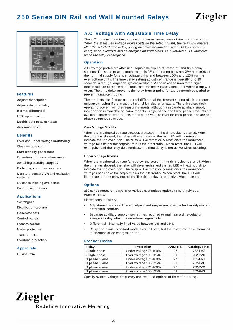
A.C. Voltage with Adjustable Time DelayThe A.C. voltage protectors provide continuous surveillance of the monitored circuit.When the measured voltage moves outside the setpoint limit, the relay will operateafter the selected time delay, giving an alarm or initiation signal. Relays normallyenergise on overvolts and de-energise on undervolts. An illuminated LED indicateswhen the relay is energised.
Operation
A.C. voltage protectors offer user adjustable trip point (setpoint) and time delaysettings. The setpoint adjustment range is 25%, operating between 75% and 100% ofthe nominal supply for under voltage units, and between 100% and 125% for theover voltage units. The time delay setting adjustment range is typically 0 to 10seconds, although longer delays are available. As soon as the monitored signalmoves outside of the setpoint limit, the time delay is activated, after which a trip willoccur. The time delay prevents the relay from tripping for a predetermined period toprevent nuisance tripping.
The products also feature an internal differential (hysteresis) setting of 1% to reducenuisance tripping if the measured signal is noisy or unstable. The units draw theiroperating power from the measuring inputs, although a separate auxiliary supplyinput option is available on some models. Single phase and three phase products areavailable, three phase products monitor the voltage level for each phase, and are notphase sequence sensitive.
Over Voltage Models
When the monitored voltage exceeds the setpoint, the time delay is started. Whenthe time has elapsed, the relay will energise and the red LED will illuminate toindicate the trip condition. The relay will automatically reset once the monitoredvoltage falls below the setpoint minus the differential. When reset, the LED willextinguish and the relay de energises. The time delay is not active when resetting.
Under Voltage Models
When the monitored voltage falls below the setpoint, the time delay is started. Whenthe time has elapsed, the relay will de-energise and the red LED will extinguish toindicate the trip condition. The relay will automatically reset once the monitoredvoltage rises above the setpoint plus the differential. When reset, the LED willilluminate and the relay energises. The time delay is not active when resetting.
Options
250 series protector relays offer various customised options to suit individualrequirements.
Please consult factory.
• Adjustment ranges - different adjustment ranges are possible for the setpoint anddifferential controls.
• Separate auxiliary supply - sometimes required to maintain a time delay or energised relay when the monitored signal fails.
• Differential - internally fixed value between 1% and 15%.
• Relay operation - standard models are fail safe, but the relays can be customised to energise or de-energise on trip.
Product Codes
Relay Protection ANSI No. Catalogue No.
Single phase Under voltage 75-100% 27 252-PVZSingle phase Over voltage 100-125% 59 252-PVH3 phase 3 wire Under voltage 75-100% 27 252-PVJ3 phase 3 wire Over voltage 100-125% 59 252-PVC3 phase 4 wire Under voltage 75-100% 27 252-PVX3 phase 4 wire Over voltage 100-125% 59 252-PVS
Specify system voltage, frequency and required options at time of ordering.
Features
Adjustable setpoint
Adjustable time delay
Internal differential
LED trip indication
Double pole relay contacts
Automatic reset
Benefits
Over and under voltage monitoring
Close voltage control
Start standby generators
Operation of mains failure units
Switching standby supplies
Protecting computer supplies
Monitors genset AVR and excitationsystems
Nuisance tripping avoidance
Customised options
Applications
Switchgear
Distribution systems
Generator sets
Control panels
Process control
Motor protection
Transformers
Overload protection
Approvals
UL and CSA
Ziegler
ZieglerRedef ine Innovat ive Meter ing

250 Series DIN Rail and Wall Mounted Relays
23
55 (2.2)
70 (
2.8)
35 (
1.37
)
112 (4.4)
RELEASE CLIP
55 (2.2)
35 (
1.37
)
17.5 (0.68)
35 (1.37) 15.5
(0.6
)12 (0.5
)
2 HOLESØ 4.1
Specification – AC Voltage with Adjustable Time Delay
Nominal Voltage 100V, 110V, 208V, 240V, 277V, 400V, 415V, 440Vor 480V
System Frequency 45/65Hz or 360/440HzVoltage Burden 0.3VAOverload 1.2 x rating continuously, 1.5 x rating for
10 x secondsSet Point Repeatability > 0.5% of full spanDifferential (Hysteresis) Preset at 1%.
Other values 1% to 10% to orderTrip Level Adjustment Under Voltage: 75 to 100%
Over Voltage: 100 to 125% of nominal input voltageTime Delay Adjustable up to 10 secondsAC Auxiliary Supply Voltage 100V, 110V, 120V, 208V, 220V, 240V, 480V, ±20%DC Auxiliary Supply Voltage 12V, 24V, 48V, 110V or 125V, ±15%. Max ripple 15%Auxiliary Voltage Burden 4VA (max)Output Relay Double pole change overRelay Contact Rating AC: 240V 5A, non inductive
DC: 24V, 5A resistiveRelay Mechanical Life 0.2 million operations at rated loadsRelay Reset AutomaticOperating Temperature 0°C to +60°C (0°C to +40°C for UL models)Storage Temperature -20°C to + 70°CTemperature Co-efficient 0.05% per °CInterference Immunity Electrical stress surge withstand and non-
function to ANSI/IEEE C37 90aEnclosure Style DIN rail with wall mounting facilityMaterial Flame retardant polycarbonate/ABSEnclosure Integrity IP50Compliant With EMC, LVD, Safety Standard IEC 414
UL File No: E113067 recognised up to 600VCSA File No: LR52592 up to 300V
Dimensions 55mm (2.2") wide x 70mm (2.8") high x 112mm (4.4") deep
Weight 0.4Kg approx.
Dimensions
Model 252
Connections
252-PVZ
252-PVH
252-PVX
252-PVS
252-PVC
252-PVJ
Note: The neutral connection is alwaysused on 4 wire systems.
RelayContact Set 1 Contact Set 2
Input Aux supplywhen required
RelayContact Set 1 Contact Set 2
Input Aux supplywhen required
Ziegler
ZieglerRedef ine Innovat ive Meter ing

250 Series DIN Rail and Wall Mounted Relays
24
A.C. Voltage with Adjustable DifferentialThe A.C. voltage protectors provide continuous surveillance of the monitored circuit.When the measured voltage moves outside the setpoint limit, the relay will operategiving an alarm or initiation signal. The protector can be used for under and overvoltage detection, start standby generators, operation of mains failure units, andswitching standby supplies. An illuminated LED indicates when the relay isenergised. The 3 phase, 3 or 4 wire models, protect each phase independently.
Operation
A.C. voltage protectors offer user adjustable trip point (setpoint) and differential(hysteresis) settings. The setpoint adjustment range is 25%, operating between 75%and 100% of the nominal supply for under voltage units, and between 100% and125% for the over voltage units. The differential setting adjustment range is 1% to15%, and it can be used to reduce nuisance tripping if the measured signal is noisyor unstable. When the measured voltage moves outside the setpoint limit, the relaywill operate, giving an alarm or initiation signal.
As soon as the monitored signal moves outside of the setpoint limit, a trip will occur.A fixed time delay is available as a factory option, preventing the relay from trippingfor a predetermined period to prevent nuisance tripping. The units draw theiroperating power from the measuring inputs, although a separate auxiliary supplyinput option is available on some models. Three phase products monitor the voltagelevel for each phase, and are not phase sequence sensitive. Combined units offerunder and over voltage trips in one compact unit. Single function units are also available.
Over Voltage Models
When the monitored voltage exceeds the setpoint, the relay will energise and the redLED will illuminate to indicate the trip condition. The relay will automatically resetonce the monitored voltage falls below the setpoint minus the differential. Whenreset, the LED will extinguish and the relay de-energises.
Under Voltage Models
When the monitored voltage falls below the setpoint, the relay will de-energise andthe red LED will extinguish to indicate the trip condition. The relay will automaticallyreset once the monitored voltage rises above the setpoint plus the differential. Whenreset, the LED will illuminate and the relay energises.
Options
250 series protector relays offer various customised options to suit individualrequirements. Please consult factory.
• Time delay - internal fixed time delay before a trip occurs.
• Separate auxiliary supply - sometimes required to maintain a time delay or energised relay when the monitored signal fails.
• Adjustment ranges - different adjustment ranges are possible for the setpoint anddifferential controls.
• Relay operation - standard models are fail safe, but the relays can be customised to energise or de-energise on trip.
Product Codes
Relay Protection ANSI No. Catalogue No.
Single phase Under voltage 75-100% 27 252-PVUSingle phase Over voltage 100-125% 59 252-PVOSingle phase Under and over voltage 27/59 253-PVB3 phase 3 wire Under voltage 75-100% 27 252-PVK3 phase 3 wire Over voltage 100-125% 59 252-PVA3 phase 3 wire Under and over voltage 27/59 253-PVM3 phase 4 wire Under voltage 75-100% 27 252-PVV3 phase 4 wire Over voltage 100-125% 59 252-PVP3 phase 4 wire Under and over voltage 27/59 253-PVE
Specify system voltage, frequency, and required options at time of ordering.
Features
Single and 3 phase models
Adjustable setpoint
Adjustable differential
Internal time delay
LED trip indication
Double pole relay contacts
Automatic reset
Benefits
Over and under voltage monitoring
Start standby generators
Operation of mains failure units
Switching standby supplies
Monitors genset AVR and excitationsystems
Nuisance tripping avoidance
Customised options
Applications
Marine panels
Switchgear
Distribution systems
Generator sets
Control panels
Process control
Motor protection
Transformers
Overload protection
Approvals
UL , CSA , BV and ABS
Ziegler
ZieglerRedef ine Innovat ive Meter ing

250 Series DIN Rail and Wall Mounted Relays
25
Connections
252-PVU
252-PVO
252-PVV
252-PVP
252-PVK
252-PVA
253-PVB
253-PVE
253-PVM
Note: The neutral connection is alwaysused on 4 wire systems.
3 Phase InputL N
Single PhaseInput
Auxsupplywhen
required
Contact Set 1 Contact Set 2Relay
Under RelayContact Set 1
Over RelayContact Set 1
Under RelayContact Set 2
Over RelayContact Set 2
Input
Input
Input
55 (2.2)
70 (
2.8)
35 (
1.37
)
112 (4.4)
RELEASE CLIP
55 (2.2)
35 (
1.37
)
17.5 (0.68)
35 (1.37) 15.5
(0.6
)12 (0.5
)
2 HOLESØ 4.1
75 (2.9)
70 (
2.8)
112.5 (4.4)
35 (
1.37
)
RELEASE CLIP
60 (2.4)
2 FIXING HOLE'A' TO SUIT M4
2 FIXING HOLE'A' TO SUIT M4
50 (
1.96
)60
(2.
36)
Specification – AC Voltage with Adjustable Differential
Nominal Voltage 100V, 110V, 120V, 208V, 220V, 270V, 280V,400V, 415V or 440V
System Frequency 45/65Hz or 360/440HzVoltage Burden 0.3VA approxOverload 1.2 x rating continuously, 1.5 x rating for
10 x secondsSet Point Repeatability >0.5% of full spanDifferential (Hysteresis) Adjustable range 1 to 15%Trip Level Adjustment Under Voltage: 75 to 100%
Over Voltage: 100 to 125% of nominal input voltageTime Delay Factory preset up to 30 secondsAC Auxiliary Supply Voltage 100V, 110V, 120V, 208V, 220V, 240V, 480V, ±20%DC Auxiliary Supply Voltage 12V, 24V, 48V, 110V or 125V, ±15%. Max ripple 15%Auxiliary Voltage Burden 4VA (max)Output Relay Double pole change overRelay Contact Rating AC: 240V 5A, non inductive
DC: 24V, 5A resistiveRelay Mechanical Life 0.2 million operations at rated loadsRelay Reset AutomaticOperating Temperature 0°C to +60°C (0°C to +40°C for UL models)Storage Temperature -20°C to + 70°CTemperature Co-efficient 0.05% per °CInterference Immunity Electrical stress surge withstand and non-
function to ANSI/IEEE C37 90aEnclosure Style DIN rail with wall mounting facilityMaterial Flame retardant polycarbonate/ABSEnclosure Integrity IP50Compliant With EMC, LVD, Safety Standard IEC 414
UL File No: E113067 recognised up to 600VCSA File No: LR52592 up to 300VBV File No: 2650H-07427-AO PRSO BV (Model 253 only)ABS File No: 93-LD 17806-X (Model 253 only)
Model 252 Dimensions 55mm (2.2") wide x 70mm (2.8") highx 112mm (4.4") deep
Model 253 Dimensions 75mm (2.9") wide x 70mm (2.8") highx 112mm (4.4") deep
Weight Model 252: 0.4Kg approx. Model 253: 0.6Kg approx
Dimensions
Model 252
Model 253
Ziegler
ZieglerRedef ine Innovat ive Meter ing

250 Series DIN Rail and Wall Mounted Relays
26
FrequencyCrompton frequency protectors give continuous surveillance of the monitored circuit.When the frequency moves outside the set point limit the relay will operate giving analarm, control or tripping signal. An illuminated LED indicates when the relay isenergised. Since speed is proportional to the frequency, this protector can be used tomonitor over and underspeed, and to protect mains supplies, computer supplies, andstandby supplies for Industrial, Hospital or Marine use.
Operation
Frequency protectors offer user adjustable frequency trip point (setpoint) anddifferential (hysteresis) settings. The setpoint adjustment range is centred around thenominal 50Hz, 60Hz or 400Hz system frequency. The differential setting adjustmentcan be used to reduce nuisance tripping if the measured signal is noisy or unstable.When the measured frequency moves outside the setpoint limit, the relay willoperate, giving an alarm or initiation signal. As soon as the monitored frequencymoves outside of the setpoint limit, a trip will occur. The units draw their operatingpower from the measuring inputs. Combined units offer under and over frequencytrips in one compact unit. Single function units are also available.
Over Frequency Models
When the monitored frequency exceeds the setpoint, the relay will energise and thered LED will illuminate to indicate the trip condition. The relay will automaticallyreset once the monitored frequency falls below the setpoint minus the differential.When reset, the LED will extinguish and the relay de-energises.
Under Frequency Models
When the monitored frequency falls below the setpoint, the relay will de-energiseand the red LED will extinguish to indicate the trip condition. The relay willautomatically reset once the monitored frequency rises above the setpoint plus thedifferential. When reset, the LED will illuminate and the relay energises.
Options
250 series protector relays offer various customised options to suit individualrequirements. Please consult factory.
• Adjustment ranges - different adjustment ranges are possible for the setpoint anddifferential controls.
• Time delay - internal fixed time delay before a trip occurs.
• Relay operation - standard models are fail safe, but the relays can be customised to energise or de-energise on trip.
Product Codes
Relay Protection ANSI No. Catalogue No.
Single phase Under frequency 81U 252-PHUSingle phase Over frequency 81O 252-PHOSingle phase Under and over frequency 81O/U 253-PHD
Specify system voltage, frequency and required options at time of ordering.
Features
Adjustable setpoint
Adjustable differential
LED trip indication
Double pole relay contacts
Automatic reset
Benefits
Over and under frequency monitoring
Over and underspeed monitoring
Start standby generators
Operation of mains failure units
Switching standby supplies
Protection of control gear
Nuisance tripping avoidance
Customised options
Applications
Marine panels
Switchgear
Distribution systems
Generator sets
Control panels
Process control
Motor protection
Transformers
Overload protection
Approvals
UL, CSA, BV and ABS
Ziegler
ZieglerRedef ine Innovat ive Meter ing

250 Series DIN Rail and Wall Mounted Relays
27
55 (2.2)
70 (
2.8)
35 (
1.37
)
112 (4.4)
RELEASE CLIP
55 (2.2)35
(1.
37)
17.5 (0.68)
35 (1.37) 15.5
(0.6
)12 (0.5
)
2 HOLESØ 4.1
75 (2.9)
70 (
2.8)
112.5 (4.4)
35 (
1.37
)
RELEASE CLIP
60 (2.4)
2 FIXING HOLE'A' TO SUIT M4
2 FIXING HOLE'A' TO SUIT M4
50 (
1.96
)60
(2.
36)
Specification – Frequency
Nominal Voltage 100V, 110V, 120V, 208V, 220V, 230V, 240V, 277V, 380V, 400V, 415V, 440V or 480V ± 20%
System Frequency 40/60Hz, 50/70Hz or 360/440HzVoltage Burden 3VAOverloads 1.2 x rating continuously, 1.5 x rating for
10 x secondsSet Point Repeatability >0.5% of full spanDifferential (Hysteresis) 40/60Hz, 50/70Hz: Adjustable 0.1 to 3.0Hz
360/440Hz: Adjustable 10 to 30HzOutput Relay Double pole change overRelay Contact Rating AC: 240V 5A, non inductive
DC: 24V, 5A resistiveRelay Mechanical Life 0.2 million operations at rated loadsRelay Reset AutomaticOperating Temperature 0°C to +60°C (0°C to +40°C for UL models)Storage Temperature -20°C to + 70°CTemperature Co-efficient 0.05% per °CInterference Immunity Electrical stress surge withstand and
non-function to ANSI/IEEE C37 90aEnclosure Style DIN rail with wall mounting facilityMaterial Flame retardant polycarbonate/ABSEnclosure Integrity IP50Compliant With EMC, LVD, Safety Standard IEC 414
UL File No: E113067 recognised up to 600VCSA File No: LR52592 up to 400Hz 300VBV File No: 2650H-07427-AO PRSO BVABS File No: 93-LD 17806-X
Model 252 Dimensions 55mm (2.2") wide x 70mm (2.8") high x 112mm (4.4") deep
Model 253 Dimensions 75mm (2.9") wide x 70mm (2.8") high x 112mm (4.4") deep
Weight Model 252: 0.4Kg approx. Model 253: 0.6Kg approx
Dimensions
Model 252
Model 253
Connections
252-PHU
252-PHO
253-PHD
Output Relay
Contact Set 1 Contact Set 2
Input
Under RelayContact Set 1
Over RelayContact Set 1
Under RelayContact Set 2
Over RelayContact Set 2
Input
Ziegler
ZieglerRedef ine Innovat ive Meter ing

250 Series DIN Rail and Wall Mounted Relays
28
Combined Under/Over Voltage and FrequencyThe 250 series combined voltage & frequency protectors provide continuoussurveillance of the monitored circuit. When the voltage or frequency moves outsidethe set point limit the respective relay will operate giving an alarm, control ortripping signal. An illuminated LED indicates when the relay is energised. Thisprotector can be used to protect against over and underspeed and over and under voltage.
Operation
Combined voltage and frequency protectors provide the most popular relay functionsin one convenient package. The products offer user adjustable trip point (setpoint)for voltage and frequency, plus adjustable time delay settings. The setpointadjustment range is 25%, operating between 75% and 100% of the nominal supplyfor under voltage, and between 100% and 125% for over voltage. The frequencysetpoint adjustment range is centred around the nominal 50Hz, 60Hz or 400Hzsystem frequency. The time delay setting adjustment range is typically 0 to 10seconds, although longer delays are available.
As soon as the monitored signal moves outside of the setpoint limit, the time delayis activated, after which a trip will occur. The time delay prevents the relay fromtripping for predetermined period to prevent nuisance tripping. The products alsofeature an internal differential (hysteresis) setting of 1% to reduce nuisance tripping ifthe measured signal is noisy or unstable. The product is available for single phasesystems only, and draws its operating power from the measuring input.
Over Voltage and Frequency
When the monitored value exceeds the setpoint and the time delay has elapsed, therelay will energise and the red LED will illuminate to indicate the trip condition.
Under Voltage and Frequency
The relay will de-energise after the time delay has elapsed, and the red LED willextinguish to indicate the trip condition.
Options
250 series protector relays offer various customised options to suit individualrequirements. Please consult factory.
• Adjustment ranges - different adjustment ranges are possible for the setpoint andtime delay controls.
• Differential - internally fixed value between 1% and 15%.
• Relay operation - standard models are fail safe, but the relays can be customised to energise or de-energise on trip.
Product Codes
Relay Protection ANSI No. Catalogue No.
Single phase Over and under voltage, 27/59, 256-PHVover and under frequency 81O/U
Specify system voltage, frequency and required options at time of ordering.
Features
Adjustable setpoint
Adjustable time delay
Internal differential
LED trip indication
Double pole relay contacts
Automatic reset
Benefits
Over and under voltage monitoring
Over and underspeed monitoring
Start standby generators
Operation of mains failure units
Switching standby supplies
Monitors genset AVR and excitationsystems
Nuisance tripping avoidance
Customised options
Applications
Switchgear
Distribution systems
Generator sets
Control panels
Process control
Motor protection
Transformers
Overload protection
Approvals
UL recognised
Ziegler
ZieglerRedef ine Innovat ive Meter ing

250 Series DIN Rail and Wall Mounted Relays
29
Under Voltage RelayContact Set 1
Over Voltage RelayContact Set 1
Under Frequency RelayContact Set 1
Over Frequency RelayContact Set 1
Contact Set 2 Contact Set 2Input
Contact Set 2 Contact Set 2
Specification – Combined Under/Over and Frequency
Nominal Voltage 100V, 110V, 120V, 208V, 220V, 270V, 280V, 400V, 415V or 440V
System Frequency 40/60Hz, 50/70Hz or 360/440HzFrequency Differential Preset at 0.1Hz (10Hz for 400Hz unit)Voltage Burden 3VAOverloads 1.2 x rating continuously, 1.5 x rating for
10 x secondsSet Point Repeatability >0.5% of full spanDifferential (Hysteresis) Fixed internally at 1%Trip Level Adjustment Over voltage: 100 to 125%
Under Voltage: 75 to 100% of nominal input voltageTime Delay Adjustable 1 to 30 secondsOutput Relay 4 independent double pole change overRelay Contact Rating AC: 240V 5A, non inductive
DC: 24V, 5A resistiveRelay Mechanical Life 0.2 million operations at rated loadsRelay Reset AutomaticOperating Temperature 0°C to +60°C (0°C to +40°C for UL models)Storage Temperature -20°C to + 70°CTemperature Co-efficient 0.05% per °CInterference Immunity Electrical stress surge withstand and non-
function to ANSI/IEEE C37 90aEnclosure Style DIN rail with wall mounting facilityMaterial Flame retardant polycarbonate/ABSEnclosure Integrity IP50Compliant With EMC, LVD, Safety Standard IEC 414
UL File No: E113067 recognised up to 600VDimensions 150mm (5.9") wide x 70mm (2.8") high
x 112mm (4.4") deepWeight 1.0Kg approx
Connections
256-PHV
Dimensions
Model 256150 (5.9)
70 (
2.8)
112.5 (4.4)
35 (
1.37
)
135 (5.3)
2 FIXING HOLE'A' TO SUIT M4
2 FIXING HOLE'A' TO SUIT M4
50 (
1.96
)
60 (
2.36
)
RELEASE CLIP
Ziegler
ZieglerRedef ine Innovat ive Meter ing

250 Series DIN Rail and Wall Mounted Relays
30
Phase Sequence and Phase FailureThe Crompton phase sequence and phase failure protector relays are designed tomonitor the correct phase rotation or sequence of three phase, 3 or 4 wire supplysystems and provide protection against incorrect phase sequence, loss of one phase,and under voltage.
Operation
Rotating machines are particularly vulnerable to incorrect phase sequence. Threephase motors can rotate in the wrong direction, potentially leading to physicaldamage or the risk of injury to personnel, yet voltage and current readings mayappear normal. If one phase is lost because of a blown fuse, electric motors cancontinue to operate (single phasing) which can result in severe electrical ormechanical damage. For permanent installations, this relay should be used tomonitor the incoming supply, protecting all equipment against incorrect connectionat initial installation or after maintenance work. Rotating machines that cannottolerate reverse rotation or pose significant risk to personnel under this conditionshould be individually protected with this relay. The possibility of incorrect supplyconnection is much more likely in portable equipment or marine applications.
The phase sequence and phase failure protectors continuously monitor the threephase supply. With the correct phase sequence applied, the front panel LED willilluminate and the output relay will be energised. An incorrect sequence or missingphase will de-energise the relay, and the LED will be extinguished. If the supplydrops below 85% of its nominal voltage, this condition will also cause a trip.
Note: If one phase is lost due to a blown fuse, some loads can re-generate themissing voltage. This relay can be used as a phase failure relay providing theregenerated voltage in the open phase is less than 70% of the nominal supplyvoltage. If there is the possibility of a higher regenerated voltage, the phase balancerelay 252-PSF should be used.
Product Codes
Relay Protection ANSI No. Catalogue No.
3 phase 3 or 4 wire Phase sequence, 47 252-PVRunder voltage 85%
Specify system voltage, frequency and required options at time of ordering.
Features
Three phase, 3 or 4 wire
LED trip indication
Double pole relay contacts
Automatic reset
Benefits
Monitoring of correct phase rotation
Protection against incorrect phasesequence and loss of phase
Under voltage monitoring
Prevents reverse rotation of motordriven equipment
Ensures correct engine rotation
Protects portable electrical equipment
Applications
Marine panels
Switchgear
Distribution systems
Generator sets
Control panels
Process control
Motor protection
Transformers
Overload protection
Approvals
UL, CSA, BV and ABS
Ziegler
ZieglerRedef ine Innovat ive Meter ing

250 Series DIN Rail and Wall Mounted Relays
31
55 (2.2)
70 (
2.8)
35 (
1.37
)
112 (4.4)
RELEASE CLIP
55 (2.2)
35 (
1.37
)
17.5 (0.68)
35 (1.37) 15.5
(0.6
)12 (0.5
)
2 HOLESØ 4.1
Connections
252-PVR
Note: No neutral connection is required.
Specification – Phase Sequence and Phase Failure
Nominal Voltage 110V, 120V, 208V, 220V, 230V, 240V, 277V,380V, 400V, 415V, 440V or 480V
Nominal Frequency 50, 60 or 400HzVoltage Burden 3VA approx.Overload 1.2 x rating continuously, 1.5 x rating for 10 x
seconds to symmetricTrip Level Adjustment Preset at 85% of nominalAuxiliary Voltage Burden 4VA (max)Output Relay Double pole change overRelay Contact Rating AC: 240V 5A, non inductive
DC: 24V, 5A resistiveRelay Mechanical Life 0.2 million operations at rated loadsRelay Reset AutomaticOperating Temperature 0°C to +60°C (0°C to +40°C for UL models)Storage Temperature -20°C to + 70°CTemperature Co-efficient 0.05% per °CInterference Immunity Electrical stress surge withstand and non-
function to ANSI/IEEE C37 90aEnclosure Style DIN rail with wall mounting facilityMaterial Flame retardant polycarbonate/ABSEnclosure Integrity IP50Compliant With EMC, LVD, US Safety Standard IEC 414
UL File No: E113067 recognised up to 600VCSA File No: LR52592 up to 300VBV File No: 2650H-07427-AO PRSO BVABS File No; 93-LD 17806-X
Model 252 Dimensions 55mm (2.2") wide x 70mm (2.8") high x 112mm (4.4") deep
Weight 0.4Kg approx.
Dimensions
Model 252
Contact Set 1 Contact Set 2Relay
Input
Ziegler
ZieglerRedef ine Innovat ive Meter ing

250 Series DIN Rail and Wall Mounted Relays
32
Phase BalanceThe 250 series phase balance protector module provides continuous surveillance of a3 phase, 3 or 4 wire system and monitors the correct phase rotation or sequence ofthree phase supply systems. The module protects against phase loss, reversal orsequence, phase unbalance, and system under voltage.
Operation
Rotating machines are particularly vulnerable to incorrect phase sequence. Threephase motors can rotate in the wrong direction, potentially leading to physicaldamage or the risk of injury to personnel, yet voltage and current readings mayappear normal. If one phase is lost because of a blown fuse, electric motors cancontinue to operate (single phasing) which can result in severe electrical ormechanical damage. This relay has the added advantage that it will detect thephantom or regenerated phase that can be caused by a single phase failure on someequipment or when running motors at low load levels.
An unbalanced supply voltage can lead to temperature rises in motors. An unbalancevoltage as little as 10% can increase operating temperature to150% of normal. Forpermanent installations, this relay should be used to monitor the incoming supply,protecting all equipment against incorrect connection at initial installation or aftermaintenance work. Rotating machines that cannot tolerate reverse rotation or posesignificant risk to personnel under this condition should be individually protectedwith this relay. The possibility of incorrect supply connection is much more likely inportable equipment or marine applications.
The protector continuously monitors the three phase supply. With the correct phasesequence applied and all three voltages balanced within the required limits, the frontpanel LED will illuminate and the output relay will be energised. An incorrectsequence, missing phase, out of balance or under voltage condition will de-energisethe relay, and the LED will be extinguished.
The setpoint control allows adjustment of the voltage matching between 5% and15%. The time delay function operates only for the voltage unbalance condition. Thedelay can be used to prevent nuisance tripping due to short term unbalancesituations. Incorrect phase rotation, a missing phase or an under voltage conditiontrip the relay immediately.
Product Codes
Relay Protection ANSI No. Catalogue No.
3 phase 3 or 4 wire Phase loss and 47 252-PSFunbalance 5 - 15%
3 phase 3 or 4 wire Phase loss, unbalance 47/27 252-PSGand under voltage 5-15%
Specify system voltage, frequency and required options at time of ordering.
Features
Three phase, 3 or 4 wire
Adjustable setpoint
Adjustable time delay
Internal differential
LED trip indication
Double pole relay contacts
Automatic reset
Benefits
Monitoring of correct phase rotation
Protects against phantom orregenerated phase voltage
Protection against phase loss, reversalor sequence
Under voltage and unbalanced voltagemonitoring
Prevents reverse rotation of motordriven equipment
Ensures correct engine rotation
Protects portable electrical equipment
Nuisance tripping avoidance
Applications
Marine panels
Switchgear
Distribution systems
Generator sets
Control panels
Process control
Motor protection
Transformers
Overload protection
Approvals
UL, CSA, BV and ABS
Ziegler
ZieglerRedef ine Innovat ive Meter ing

250 Series DIN Rail and Wall Mounted Relays
33
Connections
252-PSF
252-PSG
Note: Neutral connection not required
Specification – Phase Balance
Nominal Voltage 110V, 120V, 208V, 220V, 230V, 240V, 277V,380V, 400V, 415V, 440V or 480V
System Frequency 50 or 60HzVoltage Burden 3VA approx.Overload 1.2 x rating continuously, 1.5 x rating for
10 x secondsSet Point Repeatability >0.5% of full spanUnder Voltage Setpoint Preset at 15% of nominal voltage. Other values
10 to 30% to order (Model 252-PSG only)Trip Level Adjustment Phase unbalance adjustable 5 to 15%Time Delay 10 seconds as standard. Up to 30 seconds availableAuxiliary Voltage Burden 4VA (max)Output Relay Double pole change overRelay Contact Rating AC: 240V 5A, non inductive
DC: 24V, 5A resistiveRelay Mechanical Life 0.2 million operations at rated loadsRelay Reset AutomaticOperating Temperature 0°C to +60°C (0°C to +40°C for UL models)Storage Temperature -20°C to + 70°CTemperature Co-efficient 0.05% per °CInterference Immunity Electrical stress surge withstand and non-
function to ANSI/IEEE C37 90aEnclosure Style DIN rail with wall mounting facilityMaterial Flame retardant polycarbonate/ABSEnclosure Integrity IP50Compliant With EMC, LVD, Safety Standard IEC 414
UL File No: E113067 recognised up to 600VCSA File No: LR52592 up to 600VBV File No: 2650H-07427-AO PRSO BVABS File No; 93-LD 17806-X
Model 252 Dimensions 55mm (2.2") wide x 70mm (2.8") high x 112mm (4.4") deep
Weight 0.4Kg approx.
Dimensions
Model 252
Contact Set 1 Contact Set 2Relay
Input
55 (2.2)
70 (
2.8)
35 (
1.37
)
112 (4.4)
RELEASE CLIP
55 (2.2)
35 (
1.37
)
17.5 (0.68)
35 (1.37) 15.5
(0.6
)12 (0.5
)
2 HOLESØ 4.1
Ziegler
ZieglerRedef ine Innovat ive Meter ing

250 Series DIN Rail and Wall Mounted Relays
34
Reverse Power (Current)The reverse power protector provides continuous surveillance for A.C. generatorsoperating in parallel or for boosting mains supplies. On site adjustment of the trippoint and time delay ensures accurate protection against ‘motoring’ in the event ofengine failure and prevents tripping from surges during synchronising.
Operation
Reverse power protectors provide continuous surveillance of AC generators againstmotoring. Reverse power relays are used to detect the failure of the prime mover(engine) when active energy (Watts) flows into the generator causing rotation - theset will operate like an electric motor, which can cause significant mechanicaldamage. This relay offers an adjustable reverse power setpoint between 2% and 20%of nominal power, and time delay adjustment range of 0 to 20 seconds.
As soon as the reverse power level increases above the setpoint limit, the time delayis activated, after which a trip will occur. The time delay prevents the relay fromtripping for a predetermined period to prevent nuisance tripping. The products alsofeature an internal differential (hysteresis) setting of 1% to reduce nuisance tripping ifthe measured signal is noisy or unstable. These units are powered from themeasuring supply.
The protector relay approximates the power level in the system by measuringcurrent and power factor, but does not actually measure the system voltage. Whenthe reverse power level exceeds the setpoint, the time delay is started. When thetime has elapsed, the relay will energise and the red LED will illuminate to indicatethe trip condition. The relay will automatically reset once the power level falls below the setpoint minus the differential, the LED will extinguish and the relay de-energises. The time delay is not active when resetting. The reverse power levelwill trip as expected at the calibrated point for unity power factor, however, thesystem power factor does affect the trip point calibration. The relay becomes moresensitive at lagging power factors, as almost all systems exhibit inductance. At leading power factors, this relay is less sensitive.
Setting Up
The “% set” potentiometer trimmer on the front label is calibrated as a percentage ofthe input current rating e.g. of 5A, and not of the forward kW. Adjust the “% set”trimmer to the required tripping value, 7.5% to 10% is normal. Setting accuracy canbe checked by reversing the current lead connections and, with forward power,measuring the trip point value on a suitable ammeter (reconnect leads oncompletion). Adjust the ‘Delay’ to the required time delay, 10 seconds is normally adequate.
Options
250 series protector relays offer various customised options to suit individualrequirements. Please consult factory.
• Adjustment ranges - different adjustment ranges are possible for the setpoint and time delay controls.
• Relay operation - standard models are fail safe, but the relays can be customised to de-energise on trip.
Product Codes
Relay Protection ANSI No. Catalogue No.
Single phase or Reverse power 2 – 20% 32 256-PAS3 phase 4 wireSingle phase or 3 phase Reverse power 2 – 20% 32 256-PAQ4 wire push to test3 phase 3 wire push Reverse power 2 – 20% 32 256-PARto test3 phase 3 wire Reverse power 2 – 20% 32 256-PAT
Specify system voltage, frequency and required options at time of ordering.
Features
Three phase, 3 or 4 wire
Adjustable setpoint
Adjustable time delay
Internal differential
LED trip indication
Double pole relay contacts
Automatic reset
Benefits
Current and power factor measurement
Protects generators againsts ‘motoring’
Detects reverse power under faultconditions
Customised options
Nuisance tripping avoidance
Applications
Marine panels
Switchgear
Distribution systems
Generator sets
Control panels
Process control
Motor protection
Transformers
Overload protection
Approvals
UL, CSA, BV and ABS
Ziegler
ZieglerRedef ine Innovat ive Meter ing

250 Series DIN Rail and Wall Mounted Relays
35
Input VoltsSingle phase3 phase 4 wire
3 phase 3 wire
Contact Set 1 Contact Set 2Output Relay
Input Amps
Specification – Reverse Power (Current)
Nominal Voltage 100V, 110V, 120V, 220V, 230V, 240V, 277V, 380V, 400V, 415V, 440V or 480V
Nominal Current 5A or 2, 3, 4, 6, 8 and 10ASystem Frequency 50, 60 or 400HzBurden Voltage: 3VA maximum
Current: 2VA maximumCurrent Overload 2 x rating continuously, 10 x rating for 3 secondsVoltage Overload 1.2 x rating continuously, 1.5 x rating for
10 secondsMonitoring Range Power Factor: 0.5 inductive/unity/0.2 capacitive
Current: 20 to 100% of nominal inputSet Point Repeatability >0.5% of full spanDifferential (Hysteresis) Preset at 1%Trip Level Adjustment 2 to 20%. Customised adjustment available.Time Delay Adjustable 0 to 20 secondsAC Auxiliary Supply Voltage 100V, 110V, 120V, 208V, 220V, 240V, 480V, ±20%Auxiliary Voltage Burden 4VA (max)Output Relay Double pole change overRelay Contact Rating AC: 240V 5A, non inductive
DC: 24V, 5A resistiveRelay Mechanical Life 0.2 million operations at rated loadsRelay Reset AutomaticOperating Temperature 0°C to +60°C (0°C to +40°C for UL models)Storage Temperature -20°C to + 70°CTemperature Co-efficient 0.05% per °CInterference Immunity Electrical stress surge withstand and non-
function to ANSI/IEEE C37 90aEnclosure Style DIN rail with wall mounting facilityMaterial Flame retardant polycarbonate/ABSEnclosure Integrity IP50Compliant With EMC, LVD, Safety Standard IEC 414
UL File No: E113067 recognised up to 600VCSA File No: LR52592 up to 300VBV File No: 2650H-07427-AO PRSO BVABS File No; 93-LD 17806-X
Dimensions 150mm (5.9") wide x 70mm (2.8") high x 112mm (4.4") deep
Weight 1.0kg approx.
Connections
256-PAS
256-PAT
256-PAQ
256-PAR
Note: Only one CT connection is required, from the same phase as the voltageconnection to terminal 2.
Dimensions
Model 256150 (5.9)
70 (
2.8)
112.5 (4.4)
35 (
1.37
)
135 (5.3)
2 FIXING HOLE'A' TO SUIT M4
2 FIXING HOLE'A' TO SUIT M4
50 (
1.96
)
60 (
2.36
)
RELEASE CLIP
Ziegler
ZieglerRedef ine Innovat ive Meter ing

250 Series DIN Rail and Wall Mounted Relays
36
Synchro-Check (parallelling)The synchro-check relay can be used to assist in the semi-automatic parallelling oftwo AC power systems. The volt-free relay contacts change state when the voltagelevel, phase relationship and frequency are within the selected synchronising limits.Connecting two electrical systems that are not closely matched can cause expensivedamage and disturbance to the electrical system. Using this relay will ensure thatdamage will not occur.
Operation
As part of a manual control system, the operator will make adjustments to thegenerator voltage (excitation) and frequency (engine speed) using a synchroscope orlamps, and will then attempt to manually close the breaker. This synchro checkprotector will qualify that the two systems are closely matched before permitting thebreaker to close. As part of an automatic synchronising arrangement, this relay canbe used as an independent backup or checking device to ensure the two systems aresuitably matched before the breaker can close.
Model 256-PLL
The relay continuously monitors the voltage, phase displacement and frequency oftwo supplies. A single setpoint adjustment permits selection of suitable matching,and a red LED illuminates when the relay is energised, indicating that the twosupplies are well matched and it is safe to close the breaker.
Model- 256-PLD
This version operates in the same way as model 256-PLL, but includes an additionaldead bus detection function. If there is a requirement for a continuous supply oremergency power, then the generator can be connected without synchronising, thusensuring continuity of supply. The absence of bus voltage will cause the relay toenergise.
Product Codes
Relay Protection ANSI No. Catalogue No.
Single phase, or Phase angle and voltage 25 256-PLL3 phase 3 or 4 wire Single phase, or Phase angle and voltage 25 256-PLD3 phase 3 or 4 wire Dead bus
Specify system voltage, frequency and required options at time of ordering.
Features
Single phase or three phase, 3 or 4 wire
Live and dead bus versions
Adjustable setpoint
LED trip indication
Volt free relay contacts
Benefits
Monitors voltage phase displacementand frequency of 2 supplies
Frequency matching
Voltage matching
Phase angle matching
Synchronisation of Gen-Bus and Bus-Bus
Monitors auto synchronising systems
Assists in manual sychronisation
Applications
Marine panels
Switchgear
Distribution systems
Generator sets
Co-generation
Control panels
Approvals
UL, BV and ABS
Ziegler
ZieglerRedef ine Innovat ive Meter ing

250 Series DIN Rail and Wall Mounted Relays
37
System
3 phase 4 wire3 phase 3 wire1 phase 2 wire
GeneratorConnections
1 2L1 NL1 L2L1 N
BusbarConnections
3 4L1 NL1 L2L1 N
NormallyOpen
Contacts
NormallyClosed
Contacts
Specification – Synchro-Check (parallelling)
Nominal Voltage 100V, 110V, 120V, 208V, 220V, 230V, 240V, 277V, 380V, 400V, 415V, 440V or 480V
System Frequency 45, 50, 55, 60 or 65HzBurden Bus: 2VA Generator: 4VAOverload -25 to +30% of the nominal voltageSet Point Repeatability >0.5% of full spanDifferential (Hysteresis) Preset at 1%. Values 1% to 10% available
on requestTrip Level 10 to 30% of the nominal voltage.
6° to 20° electrical adjustmentOutput Relay 1 pair NO (normally open),
1 pair NC (normally closed)2 pair NO and 2 pair NC available on request
Relay Contact Rating AC: 240V 5A, non inductive DC: 24V, 5A resistive
Relay Mechanical Life 0.2 million operations at rated loadsRelay Reset AutomaticOperating Temperature 0°C to +60°C (0°C to +40°C for UL models)Storage Temperature -20°C to + 70°CTemperature Co-efficient 0.05% per °CInterference Immunity Electrical stress surge withstand and non-
function to ANSI/IEEE C37 90aEnclosure Style DIN rail with wall mounting facilityMaterial Flame retardant polycarbonate/ABSEnclosure Integrity IP50Compliant With EMC, LVD, Safety Standard IEC 414
UL File No: E113067 recognised up to 600VBV File No: 2650H-07427-AO PRSO BVABS File No; 93-LD 17806-X
Dimensions 150mm (5.9") wide x 70mm (2.8") high x 112mm (4.4") deep
Weight 1.0kg approx.
Connections
256-PLL
256-PLD
Dimensions
Model 256150 (5.9)
70 (
2.8)
112.5 (4.4)
35 (
1.37
)
135 (5.3)
2 FIXING HOLE'A' TO SUIT M4
2 FIXING HOLE'A' TO SUIT M4
50 (
1.96
)
60 (
2.36
)
RELEASE CLIP
Ziegler
ZieglerRedef ine Innovat ive Meter ing

250 Series DIN Rail and Wall Mounted Relays
38
D.C. VoltageDC voltage protectors provide continuous surveillance of the monitored voltagecircuit, typically a battery supply or charging circuit. When the measured voltagemoves outside the set-point limits, the relay will operate after the selected time delayor differential, giving an alarm and/or initiation signal. The protectors offer protectionfor under voltage, over voltage and battery level control.
Operation
DC voltage protectors offer user adjustable trip point (setpoint) and time delaysettings. The time delay setting adjustment range is typically 0 to 10 seconds,although longer delays up to 30 seconds are available. As soon as the monitoredsignal moves outside of the setpoint limit, the time delay is activated, after which atrip will occur. The time delay prevents the relay from tripping for a predeterminedperiod to prevent nuisance tripping. The products also feature an internal differential(hysteresis) setting of 1% to reduce nuisance tripping if the measured signal is noisyor unstable. The units draw their operating power from the measuring inputs.
Over Voltage Models
When the monitored voltage exceeds the setpoint, the time delay is started. Whenthe time has elapsed, the relay will energise and the red LED will illuminate toindicate the trip condition. The relay will automatically reset once the monitoredvoltage falls below the setpoint minus the differential. When reset, the LED willextinguish and the relay de-energises. The time delay is not active when resetting.
Under Voltage Models
When the monitored voltage falls below the setpoint, the time delay is started. Whenthe time has elapsed, the relay will de-energise and the red LED will extinguish toindicate the trip condition. The relay will automatically reset once the monitoredvoltage rises above the setpoint plus the differential. When reset, the LED willilluminate and the relay energises. The time delay is not active when resetting.
Options
250 series protector relays offer various customised options to suit individualrequirements. Please consult factory.
• Adjustment ranges - different adjustment ranges are possible for the setpoint andtime delay controls.
• Differential - Internally fixed value between 1% and 15%.
• Relay operation - standard models are fail safe, but the relays can be customised to energise or de-energise on trip.
Product Codes
Relay Protection ANSI No. Catalogue No.
DC Voltage Under voltage external 27 252-PDUtime delay
DC Voltage Under voltage differential 27 252-PDEDC Voltage Over voltage external 59 252-PDO
time delayDC Voltage Over and under voltage 27/59 253-PDC
external time delay
Specify system voltage, frequency and required options at time of ordering.
Features
Adjustable setpoint
Adjustable time delay
Internal differential
LED trip indication
Automatic reset
Double pole relay contacts
Benefits
Over and under voltage monitoring
Monitors correct terminal voltage onbattery supplies
Monitors charging voltage on batterychargers
Battery level control
Nuisance tripping avoidance
Customised options
Applications
Marine panels
Switchgear
Distribution systems
Generator sets
Control panels
Process control
Overload protection
Approvals
UL recognised
Ziegler
ZieglerRedef ine Innovat ive Meter ing

250 Series DIN Rail and Wall Mounted Relays
39
55 (2.2)
70 (
2.8)
35 (
1.37
)
112 (4.4)
RELEASE CLIP
55 (2.2)
35 (
1.37
)
17.5 (0.68)
35 (1.37) 15.5
(0.6
)12 (0.5
)
2 HOLESØ 4.1
75 (2.9)
70 (
2.8)
112.5 (4.4)
35 (
1.37
)
RELEASE CLIP
60 (2.4)
2 FIXING HOLE'A' TO SUIT M4
2 FIXING HOLE'A' TO SUIT M4
50 (
1.96
)60
(2.
36)
Specification – D.C. Voltage
Nominal Voltage 18 to 20V DC or 20 to 32V DCVoltage Burden <3VAOverload 1.2 x rating continuouslySet Point Repeatability >0.5% of full spanDifferential (Hysteresis) Models 252-PDU, 252-PDO & 253-PDC: Preset at 1%.
Values 1% to 15% available on requestModel 252-PDE: Adjustable 1 to 15%
Time Delay Adjustment Models 252-PDU, 252-PDO & 253-PDC: 0-10, 0-20, 0-30 secondsModel 252-PDE: Factory pre-set up to 30 seconds.
AC Auxiliary Supply Voltage 100V, 110V, 120V, 208V, 220V, 240V, 480V, ±20%DC Auxiliary Supply Voltage 12V, 24V, 48V, 110V or 125V, ±15%. Max ripple 15%Auxiliary Voltage Burden 4VA (max)Output Relay Double pole change overRelay Contact Rating AC: 240V 5A, non inductive
DC: 24V, 5A resistiveRelay Mechanical Life 0.2 million operations at rated loadsRelay Reset AutomaticOperating Temperature 0°C to +60°C (0°C to +40°C for UL models)Storage Temperature -20°C to + 70°CTemperature Co-efficient 0.05% per °CInterference Immunity Electrical stress surge withstand and non-
function to ANSI/IEEE C37 90aEnclosure Style DIN rail with wall mounting facilityMaterial Flame retardant polycarbonate/ABSEnclosure Integrity IP50Compliant With EMC, LVD, Safety Standard IEC 414
UL File No: E113067 recognised up to 600VModel 252 Dimensions 55mm (2.2") wide x 70mm (2.8") high
x 112mm (4.4") deepModel 253 Dimensions 75mm (2.9") wide x 70mm (2.8") high
x 112mm (4.4") deepWeight Model 252: 0.4Kg approx.
Model 253: 0.6Kg approx
Dimensions
Model 252
Connections
Model 253
Connections
252-PDU
252-PDO
252-PDE
253-PDC
Contact Set 1 Contact Set 2Relay
Input
Auxsupplywhen
required
Input
Contact Set 1 Contact Set 2Relay
MonitoredValue
Under RelayContact Set 1
Over RelayContact Set 1
SupplyUnder RelayContact Set 2
Over RelayContact Set 2
Ziegler
ZieglerRedef ine Innovat ive Meter ing

250 Series DIN Rail and Wall Mounted Relays
40
Thermistor TripMany motors, transformers and generators are fitted with positive temperature co-efficient thermistor temperature sensors, the addition of a thermistor trip relay willprovide full protection against sustained overload, single phasing, locked rotor,blocked ventilation and high ambient temperature. Thermistor trip relayscontinuously monitor the working temperature inside electrical equipment. When thetemperature exceeds a safe limit, the relay can be used to shut equipment down untilit regains a safe operating temperature.
Operation
Thermistors are simple low cost temperature sensors. The thermistor trip protectoroperates by de-energising a relay when the thermistors detect a critical temperaturecondition. An illuminated green LED indicates when the temperature is within normalworking limits. Any number of thermistors may be used in series connectionproviding the resistance at normal working temperature is less than 1500 ohms.
There are no user adjustments on this relay.
Model 252-PMT will automatically reset when temperature returns to normal. ForModel 252-PMM, fitting a link between terminals R1 and R2 will latch the product inits tripped state when an over temperature condition is detected. The relay can bereset by pressing the front panel reset switch, opening the R1 - R2 link, orinterrupting the auxiliary supply.
Product Codes
Relay Protection ANSI No. Catalogue No.
PTC Thermistors Over temperature, 49 252-PMMmanual reset
PTC Thermistors Over temperature, 49 252-PMTautomatic reset
Specify system voltage and required options at time of ordering.
Features
Trip range 2500 to 3500 ohms
Reset range 1500 to 2300 ohms
LED trip indication
Automatic or manual reset options
Double pole relay contacts
Benefits
High temperature protection
Sustained overload protection
Single phasing protection
Locked rotor protection
Blocked ventilation protection
Applications
Switchgear
Distribution systems
Generator sets
Control panels
Process control
Motor protection
Transformers
Overload protection
Approvals
UL and CSA
Ziegler
ZieglerRedef ine Innovat ive Meter ing

250 Series DIN Rail and Wall Mounted Relays
41
55 (2.2)
70 (
2.8)
35 (
1.37
)
112 (4.4)
RELEASE CLIP
55 (2.2)
35 (
1.37
)
17.5 (0.68)
35 (1.37) 15.5
(0.6
)12 (0.5
)
2 HOLESØ 4.1
Specification – Thermistor Trip
Nominal Voltage 110V, 120V, 220V, 230V or 240V AC ±20%.Input Positive temperature coefficient thermistors
(series connected 1500Ω at normal temperature)System Frequency 50/60HzVoltage Burden 2VA approxOverload 1.2 x rating continuouslyTrip Level 2500 to 3500Ω reset 1500 to 2300ΩAC Auxiliary Supply Voltage 100V, 110V, 120V, 208V, 220V, 240V, 480V, ±20%DC Auxiliary Supply Voltage 12V, 24V, 48V, 110V or 125V, ±15%. Max ripple 15%Auxiliary Voltage Burden 4VA (max)Output Relay Double pole change overRelay Contact Rating AC: 240V 5A, non inductive
DC: 24V, 5A resistiveRelay Mechanical Life 0.2 million operations at rated loadsRelay Reset Model 252-PMT: Automatic
Model 252-PMM: ManualOperating Temperature 0°C to +60°C (0°C to +40°C for UL models)Storage Temperature -20°C to + 70°CTemperature Co-efficient 0.05% per °CInterference Immunity Electrical stress surge withstand and non-
function to ANSI/IEEE C37 90aEnclosure Style DIN rail with wall mounting facilityMaterial Flame retardant polycarbonate/ABSEnclosure Integrity IP50Compliant With EMC, LVD, Safety Standard IEC 414
UL File No: E113067 recognised up to 600VCSA File No: LR52592 up to 300V
Model 252 Dimensions 55mm (2.2") wide x 70mm (2.8") high x 112mm (4.4") deep
Weight 0.4Kg approx.
Dimensions
Model 252
Connections
252-PMT
252-PMM
Contact Set 1 Contact Set 2
Contact Set 1 Contact Set 2
Output Relay
Output Relay
Supply
SupplyThermistor
Connections
ThermistorConnections
Ziegler
ZieglerRedef ine Innovat ive Meter ing

250 Series DIN Rail and Wall Mounted Relays
42
Hot Spot 3 Temperature RelayThe Hot Spot 3 relay accepts up to three inputs from resistance temperaturedetectors (RTD) and provides up to three user adjustable trip points which can beused to initiate alarms, cooling systems or shutdown. The relay is ideally suited forthe protection of electric motor windings, transformers, generator windings andbearing temperature. The analogue output can be used for remote monitoring of high temperatures.
Operation
RTD temperature sensors are often fitted inside electric motors to detect hot spots inthe windings or the bearings. RTD sensors are popular because they offer a goodaccuracy for a reasonable price. The same sensors can be used inside transformers,generator sets, gas turbines or as part of a process control system. Hot spots can becaused by many conditions, such as overloads, over voltage, unbalanced supply,worn bearings, ineffective cooling, poor ventilation, shorted turns, insulationbreakdown, single phasing etc.
The Hot Spot 3 protector continuously monitors the three RTD temperature sensors,and offers up to three user adjustable setpoints and relay contacts. These can beused to raise alarms, switch on cooling systems or shut down the effectedequipment. The highest temperature is indicated with a yellow LED, and can beaccurately measured or remotely displayed using the 0/1mA analogue output signal.
The temperature is compared with the user adjustable setpoints. When the measuredtemperature exceeds the setpoint, the relay will de-energise, and a red LEDilluminated to indicate the trip condition. When the temperature drops below thesetpoint, the relay will reset to the energised condition, and the LED will extinguish.The range consists of three product models which offers one, two or threeadjustable setpoints.
Product Codes
Relay Protection ANSI No. Catalogue No.
3 RTD inputs 3 set points 49 256-PRA3 RTD inputs 2 set points 49 256-PRB3 RTD inputs 1 set point 49 256-PRC
When ordering please supply the following information:
• System voltage, frequency and required options.
• The type of temperature sensor being used, e.g. Platinum PT100.
• The maximum temperature or meter scale, e.g. 100% = 1mA = 150°C.
• The setpoint adjustment range, e.g. 0°C to 150°C.
Features
Up to 3 RTD inputs
1mA analogue output
3 adjustable setpoints
Internal differential
LED trip indication
Automatic reset
3 single pole relay contacts
Benefits
Temperature monitoring
Unbalanced supply protection
Sustained overload protection
Single phasing protection
Blocked ventilation protection
Protection against ineffective cooling
Protection of bearing temperature
Applications
Switchgear
Distribution systems
Generator sets
Control panels
Process control
Motor monitoring
Transformers
Overload protection
Approvals
UL recognised
Ziegler
ZieglerRedef ine Innovat ive Meter ing
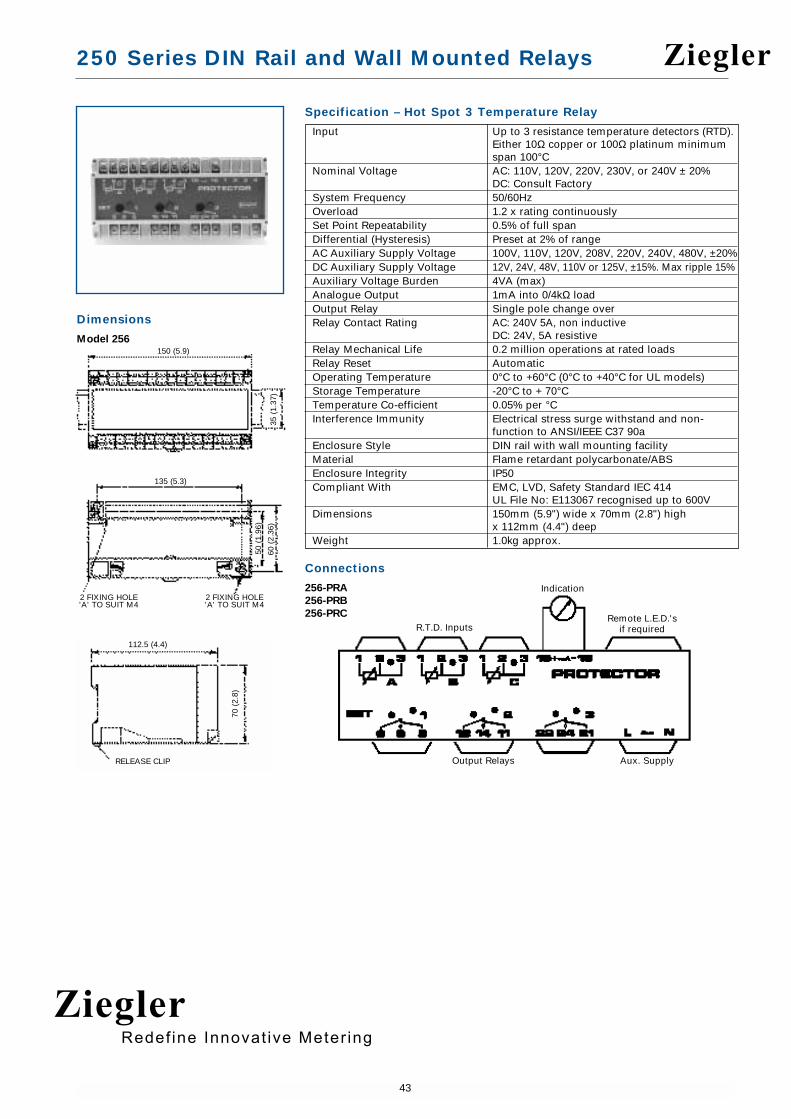
250 Series DIN Rail and Wall Mounted Relays
43
R.T.D. InputsRemote L.E.D.'s
if required
Indication
Output Relays Aux. Supply
Specification – Hot Spot 3 Temperature Relay
Input Up to 3 resistance temperature detectors (RTD).Either 10Ω copper or 100Ω platinum minimum span 100°C
Nominal Voltage AC: 110V, 120V, 220V, 230V, or 240V ± 20%DC: Consult Factory
System Frequency 50/60HzOverload 1.2 x rating continuouslySet Point Repeatability 0.5% of full spanDifferential (Hysteresis) Preset at 2% of rangeAC Auxiliary Supply Voltage 100V, 110V, 120V, 208V, 220V, 240V, 480V, ±20%DC Auxiliary Supply Voltage 12V, 24V, 48V, 110V or 125V, ±15%. Max ripple 15%Auxiliary Voltage Burden 4VA (max)Analogue Output 1mA into 0/4kΩ loadOutput Relay Single pole change overRelay Contact Rating AC: 240V 5A, non inductive
DC: 24V, 5A resistiveRelay Mechanical Life 0.2 million operations at rated loadsRelay Reset AutomaticOperating Temperature 0°C to +60°C (0°C to +40°C for UL models)Storage Temperature -20°C to + 70°CTemperature Co-efficient 0.05% per °CInterference Immunity Electrical stress surge withstand and non-
function to ANSI/IEEE C37 90aEnclosure Style DIN rail with wall mounting facilityMaterial Flame retardant polycarbonate/ABSEnclosure Integrity IP50Compliant With EMC, LVD, Safety Standard IEC 414
UL File No: E113067 recognised up to 600VDimensions 150mm (5.9") wide x 70mm (2.8") high
x 112mm (4.4") deepWeight 1.0kg approx.
Connections
256-PRA
256-PRB
256-PRC
Dimensions
Model 256150 (5.9)
70 (
2.8)
112.5 (4.4)
35 (
1.37
)
135 (5.3)
2 FIXING HOLE'A' TO SUIT M4
2 FIXING HOLE'A' TO SUIT M4
50 (
1.96
)
60 (
2.36
)
RELEASE CLIP
Ziegler
ZieglerRedef ine Innovat ive Meter ing

250 Series DIN Rail and Wall Mounted Relays
44
Hot Spot 6 Temperature RelayThe Hot Spot 6 protector is a temperature trip relay accepting up to six inputs fromresistance temperature detector (RTD) elements and provides one user adjustabletrip point which can be used to initiate alarms, cooling or shutdown when themonitored temperature exceeds the set limit. The relay is ideally suited for theprotection of electric motor windings, transformers, generator windings and bearing temperature.
Operation
RTD temperature sensors are often fitted inside electric motors to detect hot spots inthe windings or bearings. RTD sensors are popular because they offer a goodaccuracy for a reasonable price. The same sensors can be used inside transformers,generator sets, gas turbines or as part of a process control system. Hot spots can becaused by many conditions, such as overloads, over voltage, unbalanced supply,worn bearings, ineffective cooling, poor ventilation, shorted turns, insulationbreakdown, single phasing etc.
The Hot Spot 6 protector continuously monitors the six RTD temperature sensors,and offers a user adjustable setpoint and relay contacts. This can be used to raisealarms, switch on cooling systems or shut down the effected equipment. The highestof the six temperatures is indicated with a red LED. This temperature is comparedwith the user adjustable setpoint. When the measured temperature exceeds thesetpoint, the relay will de-energise, and the red LED illuminates to indicate the tripcondition. When the temperature drops below the setpoint, the relay will reset to theenergised condition, and a green LED will illuminate to indicate 'Safe' condition.
Product Codes
Relay Protection ANSI No. Catalogue No.
6 RTD inputs 1 setpoint 49 256-PCC
When ordering please supply the following information:
• System voltage, frequency and required options.
• The type of temperature sensor being used, e.g. Platinum PT100.
• The maximum temperature or meter scale, e.g. 100% = 1mA = 150°C
• The setpoint adjustment range, e.g. 0°C to 150°C.
Features
Up to 6 RTD inputs
Adjustable setpoint
Internal differential
LED trip indication
Automatic reset
Single pole relay contacts
Benefits
Unbalanced supply protection
Sustained overload protection
Single phasing protection
Blocked ventilation protection
Protection against ineffective cooling
Protection of bearing temperature
Applications
Switchgear
Distribution systems
Generator sets
Control panels
Process control
Motor monitoring
Transformers
Overload protection
Approvals
UL recognised
Ziegler
ZieglerRedef ine Innovat ive Meter ing

250 Series DIN Rail and Wall Mounted Relays
45
Specification – Hot Spot 6 Temperature Relay
Input Up to 6 resistance temperature detectors (RTD).Either 10Ω copper or 100Ω platinum minimum span 100°C
Nominal Voltage AC: 110V, 120V, 220V, 230V, or 240V ± 20%DC: Consult Factory
System Frequency 50/60HzVoltage Burden 6VA maximumOverload 1.2 x rating continuouslySet Point Repeatability Within 1°CDifferential (Hysteresis) 4°C of nominalTrip Level Adjustment 100°C (eg: 50 to 150°C, 100 to 200°C etc)Time Delay Typically 250msAC Auxiliary Supply Voltage 100V, 110V, 120V, 208V, 220V, 240V, 480V, ±20%DC Auxiliary Supply Voltage 12V, 24V, 48V, 110V or 125V, ±15%. Max ripple 15%Auxiliary Voltage Burden 4VA (max)Output Relay Single pole change overRelay Contact Rating AC: 240V 5A, non inductive
DC: 24V, 5A resistiveRelay Mechanical Life 0.2 million operations at rated loadsRelay Reset AutomaticOperating Temperature 0°C to +60°C (0°C to +40°C for UL models)Storage Temperature -20°C to + 70°CTemperature Co-efficient 0.05% per °CInterference Immunity Electrical stress surge withstand and non-
function to ANSI/IEEE C37 90aEnclosure Style DIN rail with wall mounting facilityMaterial Flame retardant polycarbonate/ABSEnclosure Integrity IP50Compliant With EMC, LVD, Safety Standard IEC 414
UL File No: E113067 recognised up to 600VDimensions 150mm (5.9") wide x 70mm (2.8") high
x 112mm (4.4") deepWeight 1.0kg approx.
Connections
256-PCC
When used for less than 6 RTD inputs the unused terminals 1, 2 & 3 must belinked together.
Dimensions
Model 256150 (5.9)
70 (
2.8)
112.5 (4.4)
35 (
1.37
)
135 (5.3)
2 FIXING HOLE'A' TO SUIT M4
2 FIXING HOLE'A' TO SUIT M4
50 (
1.96
)
60 (
2.36
)
RELEASE CLIP
Ziegler
ZieglerRedef ine Innovat ive Meter ing

250 Series DIN Rail and Wall Mounted Relays
46
D.C. Millivolts / ThermocoupleThe 250 series millivolt protectors provide continuous surveillance of high DCcurrents when used with current shunts, or can be used to monitor temperatures inconjunction with thermocouples. The protector incorporates a user adjustable tripand time delay which can be set to initiate an alarm when the input exceeds thedesired level.
Operation
When used in conjunction with current shunts the millivolt protector can be used tomonitor battery charging currents, current drain or over/under current. Monitoring ofunder / over temperature and detection of hotspots can be achieved in applicationsusing thermocouples. All industry standard shunts, and all popular thermocouplesare supported.
The millivolt protector relays offer user adjustable trip point (setpoint) and time delaysettings. The time delay setting adjustment range is typically 0 to 10 seconds,although longer delays are available. As soon as the monitored signal moves outsideof the setpoint limit, the time delay is activated, after which a trip will occur. The timedelay prevents the relay from tripping for a predetermined period to preventnuisance tripping. These products also feature an internal differential (hysteresis)setting of 1% to reduce nuisance tripping if the measured signal is noisy or unstable.These units require an auxiliary power supply.
'Over' High Trip Models
When the monitored signal exceeds the setpoint, the time delay is started. When thetime has elapsed, the relay will energise and the red LED will illuminate to indicatethe trip condition. The relay will automatically reset once the monitored signal fallsbelow the setpoint minus the differential. When reset, the LED will extinguish andthe relay de-energises. The time delay is not active when resetting.
'Under' Low Trip Models
When the monitored signal falls below the setpoint, the time delay is started. Whenthe time has elapsed, the relay will de-energise and the red LED will extinguish toindicate the trip condition. The relay will automatically reset once the monitoredsignal rises above the setpoint plus the differential. When reset, the LED willilluminate and the relay energises. The time delay is not active when resetting.
Options
250 series protector relays offer various customised options to suit individualrequirements. Please consult factory.
• Adjustment ranges - different adjustment ranges are possible for the setpoint andtime delay controls.
• Differential - Internally fixed value between 1% and 15%.
• Relay operation - standard models are failsafe, but the relays can be customised to energise or de-energise on trip.
• Cold junction compensation available on request.
Product Codes
Relay Protection ANSI No. Catalogue No.
DC Millivolt High trip 40 to 120% 74 252-PBTDC Millivolt Low trip 0 to 80% 74 252-PBSThermocouple Type J, K, R, S and T. 49 252-PTO
High trip 40 to 120%Thermocouple Type J, K, R, S and T. 49 252-PTU
Low trip 0 to 80%
For models 252-PBS and 252-PBT specify millivolt input, auxiliary voltage andrequired options at time of ordering.
For models 252-PTO and 252-PTU specify thermocouple type, nominal temperature,auxiliary voltage and required options at time of ordering.
Features
High and low trip models
Adjustable setpoint
Adjustable time delay
Internal differential
LED trip indication
Automatic reset
Double pole relay contacts
Supports all industry standard shuntsand popular thermocouples
Benefits
Under / Over temperature monitoring
Under / Over current monitoring
Monitoring of battery charging currentsand current drain
Detection of hotspots
Nuisance tripping avoidance
Customised options
Applications
Switchgear
Distribution systems
Generator sets
Control panels
Process control
Motor protection
Transformers
Overload protection
Approvals
UL and CSA
Ziegler
ZieglerRedef ine Innovat ive Meter ing

250 Series DIN Rail and Wall Mounted Relays
47
55 (2.2)
70 (
2.8)
35 (
1.37
)
112 (4.4)
RELEASE CLIP
55 (2.2)
35 (
1.37
)
17.5 (0.68)
35 (1.37) 15.5
(0.6
)12 (0.5
)2 HOLES
Ø 4.1
Specification – DC Millivolts / Thermocouple
DC Input 10mV, 50mV, 60mV, 75mV, 100mV, 150mVInput Impedance 50KΩSource Impedance 100Ω maximumThermocouple Types J, K, R, S, T 10 to 50mVThermocouple TBP Thermocouple break protection upscale drive
as standardThermocouple CJC Cold junction compensation available on requestThermocouple Overload 10 x rating continuouslyNominal Frequency 50/60HzVoltage Burden 3VA maximumVoltage Overload 1.2 x rating continuously, 1.5 x rating for
10 secondsSet Point Repeatability >0.5% of full spanDifferential (Hysteresis) Preset at 1%.
Values 1% to 15% available on requestTrip Level Adjustment Low trip: 0 to 80%
High trip: 40 to 120%Time Delay Adjustable 0 to 10 secondsAC Auxiliary Supply Voltage 100V, 110V, 120V, 208V, 220V, 240V, 480V, ±20%DC Auxiliary Supply Voltage 12V, 24V, 48V, 110V or 125V, ±15%. Max ripple 15%Auxiliary Voltage Burden 4VA (max)Output Relay Double pole change overRelay Contact Rating AC: 240V 5A, non inductive
DC: 24V, 5A resistiveRelay Mechanical Life 0.2 million operations at rated loadsRelay Reset AutomaticOperating Temperature 0°C to +60°C (0°C to +40°C for UL models)Storage Temperature -20°C to + 70°CTemperature Co-efficient 0.05% per °CInterference Immunity Electrical stress surge withstand and non-
function to ANSI/IEEE C37 90aEnclosure Style DIN rail with wall mounting facilityMaterial Flame retardant polycarbonate/ABSEnclosure Integrity IP50Compliant With EMC, LVD, Safety Standard IEC 414
UL File No: E113067 recognised up to 600VCSA File No: LR52592 up to 150mV (252-PBS & 252-PBT only)
Dimensions 55mm (2.2") wide x 70mm (2.8") high x 112mm (4.4") deep
Weight 0.4Kg approx.
Dimensions
Model 252
Connections
252-PBT
252-PBS
252-PTU
252-PTOContact Set 1 Contact Set 2
Relay
MonitoredValue
Supply
Ziegler
ZieglerRedef ine Innovat ive Meter ing

250 Series DIN Rail and Wall Mounted Relays
48
D.C. Transducer TripDC transducer protectors provide continuous surveillance of the DC process voltageor current signal. When the standard process signals move outside the setpoint limitthe relay will operate. Combining the protection relay with a measuring transducersuch as the Crompton ‘Paladin’ range can form specialised control productswhenever self contained relays are not available.
Operation
The DC transducer protector relay offers user adjustable trip point (setpoint) and timedelay settings. The time delay setting adjustment range is typically 0 to 10 seconds,although longer delays are available. As soon as the monitored signal moves outsideof the setpoint limit, the time delay is activated, after which a trip will occur. The timedelay prevents the relay from tripping for a predetermined period to preventnuisance tripping. The products also feature an internal differential (hysteresis)setting of 1% to reduce nuisance tripping if the measured signal is noisy or unstable.These units require an auxiliary power supply.
'Over' High Trip Models
When the monitored signal exceeds the setpoint, the time delay is started. When thetime has elapsed, the relay will energise and the red LED will illuminate to indicatethe trip condition. The relay will automatically reset once the monitored signal fallsbelow the setpoint minus the differential. When reset, the LED will extinguish andthe relay de-energises. The time delay is not active when resetting.
'Under' Low Voltage Models
When the monitored signal falls below the setpoint, the time delay is started. Whenthe time has elapsed, the relay will de-energise and the red LED will extinguish toindicate the trip condition. The relay will automatically reset once the monitoredsignal rises above the setpoint plus the differential. When reset, the LED willilluminate and the relay energises. The time delay is not active when resetting.
Options
250 series protector relays offer various customised options to suit individualrequirements. Please consult factory.
• Adjustment ranges - different adjustment ranges are possible for the setpoint andtime delay controls.
• Differential - Internally fixed value between1% and 15%.
• Relay operation - standard models are fail safe, but the relays can be customised to energise or de-energise on trip.
Product Codes
Relay Protection ANSI No. Catalogue No.
DC Transducer Low trip 0 to 80% 74 252-PBADC Transducer High trip 40 to 120% 74 252-PBBDC Transducer High and low trip 74 253-PBV
Specify, input current/voltage, auxiliary voltage and required options at time ofordering.
Features
High and low trip models
Adjustable setpoint
Adjustable time delay
Internal differential
LED trip indication
Automatic reset
Double pole relay contacts
Benefits
Accepts standard process voltage orcurrent signals
Monitors forward/reverse Watts, VArand VA
Monitors under/over Watts, VAr and VA
Power factor monitoring and control
Nuisance tripping avoidance
Customised options
Applications
Switchgear
Distribution systems
Generator sets
Control panels
Process control
Motor protection
Transformers
Overload protection
Approvals
UL and CSA
Ziegler
ZieglerRedef ine Innovat ive Meter ing

250 Series DIN Rail and Wall Mounted Relays
49
55 (2.2)
70 (
2.8)
35 (
1.37
)
112 (4.4)
RELEASE CLIP
55 (2.2)
35 (
1.37
)
17.5 (0.68)
35 (1.37) 15.5
(0.6
)12 (0.5
)
2 HOLESØ 4.1
75 (2.9)
70 (
2.8)
112.5 (4.4)
35 (
1.37
)
RELEASE CLIP
60 (2.4)
2 FIXING HOLE'A' TO SUIT M4
2 FIXING HOLE'A' TO SUIT M4
50 (
1.96
)60
(2.
36)
Specification – DC Transducer Trip
Nominal Input Current DC 0-1mA, 0-5mA, 0-10mA, 0-20mA, 4-20mA. Volt drop 1V
Nominal Input Voltage DC 1V to 50V, input resistance 10kΩ/VVoltage Burden 3VA maximumOverload 1.2 x rating continuously, 1.5 x rating for 10 secondsSet Point Repeatability >0.5% of full spanDifferential (Hysteresis) Preset at 1%.
Values 1% to 15% available on requestTrip Level Adjustment Low trip: 0 to 80%
High trip: 40 to 120%Time Delay Adjustable 0 to 10 secondsAC Auxiliary Supply Voltage 100V, 110V, 120V, 208V, 220V, 240V, 480V, ±20%DC Auxiliary Supply Voltage 12V, 24V, 48V, 110V or 125V, ±15%. Max ripple 15%Auxiliary Voltage Burden 4VA (max)Output Relay Double pole change overRelay Contact Rating AC: 240V 5A, non inductive
DC: 24V, 5A resistiveRelay Mechanical Life 0.2 million operations at rated loadsRelay Reset AutomaticOperating Temperature 0°C to +60°C (0°C to +40°C for UL models)Storage Temperature -20°C to + 70°CTemperature Co-efficient 0.05% per °CInterference Immunity Electrical stress surge withstand and non-
function to ANSI/IEEE C37 90aEnclosure Style DIN rail with wall mounting facilityMaterial Flame retardant polycarbonate/ABSEnclosure Integrity IP50Compliant With EMC, LVD, Safety Standard IEC 414
UL File No: E113067 recognised up to 600VCSA File No: LR52592 up to 240V AC
Model 252 Dimensions 55mm (2.2") wide x 70mm (2.8") high x 112mm (4.4") deep
Model 253 Dimensions 75mm (2.9") wide x 70mm (2.8") high x 112mm (4.4") deep
Weight Model 252: 0.4Kg approx. Model 253: 0.6Kg approx
Dimensions
Model 252
Model 253
Connections
252-PBB
252-PBA
253-PBV
Contact Set 1 Contact Set 2Relay
SupplyMonitoredValue
MonitoredValue
Under RelayContact Set 1
Over RelayContact Set 1
SupplyUnder RelayContact Set 2
Over RelayContact Set 2
Ziegler
ZieglerRedef ine Innovat ive Meter ing

250 Series DIN Rail and Wall Mounted Relays
50
Features
1mA analogue output
3 adjustable setpoints
Adjustable time delay
Internal differential
LED trip indication
Automatic reset
3 single pole relays
Magnetic pick up input
Benefits
Under/over speed monitoring
Speed indicator output signal
Zero reset cranking
Nuisance tripping avoidance
Customised options
Applications
Marine panels
Switchgear
Distribution systems
Generator sets
Control panels
Process control
Motor protection
Transformers
Overload protection
Approvals
UL recognised
Speed SensingThe 250 series speed sensing relay monitors rotating equipment and provides threeoutput contacts which can be used to initiate alarm or shutdown signals. The relayalso provides a tachometer output for speed indication. Speed sensing relays areideally suited for engine and gas turbine monitoring and the protection of generator sets.
Operation
The speed sensing protector monitors the speed of rotation using a low costmagnetic pickup. Speed sensors are often used in generator set engines, gasturbines, motors, gear boxes or any rotating machines. The relay will detect underspeed, over speed and stopped conditions, and the setpoint relays can be used toraise an alarm or shut down the equipment. The relay provides three user adjustabletrip levels with LED relay state indication and a speed indicator output signal.
The product also offers an analogue output that can be used to monitor or displaythe speed. The product operates from the 12V or 24V dc battery supply, and speed ismeasured and calculated from the number of sensor pulses per revolution. Since thesensor is magnetic, a rotating steel component can be used, such as the flywheelwhich has gear teeth. This will result in a large number of pulses per revolution, andlead to greater accuracy.
The protector continuously monitors the rotation speed, and updates the analogueoutput signal. An output of 0.75 mA indicates normal speed (100%) while 1mAindicates 133% of nominal speed. The calibration point can easily be user adjusted.Three setpoint control adjustments allow setting of the desired speed limits forcranking, under speed and over speed.
Cranking Relay
The cranking relay detects if the engine is running or stopped. This relay can be usedto ensure the cranking motor is disconnected once the engine has started running.Set the cranking setpoint just above the cranking motor speed. A red LED illuminateswhen the relay is energised, indicating a trip condition. The crank relay will onlyreset when the input frequency falls below 20% of the crank set point.
Under Speed Relay
The under speed relay detects when the normal running speed has been achieved.This can be used to enable the generator's electrical protection. It can also be used totrigger load shedding. A red LED illuminates when an under speed condition exists.
Over Speed Relay
The overspeed relay detects a stuck throttle or overshoot, a break in the sensor loadwill de-energise the over speed relay and can be used to shut down the engine. Ared LED indicates over speed trip.
Fail Safe Operation
The relay will detect an open circuit speed sensor, and de-energise the overspeedrelay.
Product Codes
Relay Protection ANSI No. Catalogue No.
Speed Sensing Crank 10 to 50% 12/14 253-PH3Under speed 50 to 100%Over speed 100 to 130%
When ordering please supply the following information:
• The number of pulses per revolution, e.g. flywheel teeth = 30.• The nominal running speed, e.g. 3600 RPM.• The DC battery supply, e.g. 24 V dc.
The protector speed sensing relay provides three user adjustable trip levels with LEDrelay state indication and a speed indicator output signal. Please specify:
• SP1 - disengages the crank starter.• SP2 - energises protection or under-speed alarm.• SP3 - alarms or trips on overspeed.
Ziegler
ZieglerRedef ine Innovat ive Meter ing

250 Series DIN Rail and Wall Mounted Relays
51
55 (2.2)
70 (
2.8)
35 (
1.37
)
112 (4.4)
RELEASE CLIP
55 (2.2)
35 (
1.37
)
17.5 (0.68)
35 (1.37) 15.5
(0.6
)12 (0.5
)
2 HOLESØ 4.1
Specification – Speed Sensing
Pulse Input (Magnetic Input) 5V – 75V peak to peakFrequency Input 0-1 to 0-10kHzOverload 1.2 x rating continuouslySet Point Repeatability >0.5% of full spanDifferential (Hysteresis) Preset at 2% (SP1 version resets at 20%
of setting)Trip Level Adjustment SP1 (crank): 10% to 50%
SP2 (under speed) : 50% to 100%SP3 (over speed) 100% to 130%
AC Auxiliary Supply Voltage 100V, 110V, 120V, 208V, 220V, 240V, 480V, ±20%DC Auxiliary Supply Voltage 12V or 24V ±20%Auxiliary Voltage Burden 3VA (max)Analogue Output 0.75mA for normal 100% speed.
1mA for 133% of nominal speedCalibration Signal 0-1mA into 0-1000 ohmsOutput Relay 3 single pole change over relaysRelay Contact Rating AC: 240V 5A, non inductive
DC: 24V, 5A resistiveRelay Mechanical Life 0.2 million operations at rated loadsRelay Reset AutomaticOperating Temperature 0°C to +60°C (0°C to +40°C for UL models)Storage Temperature -20°C to + 70°CTemperature Co-efficient 0.05% per °CInterference Immunity Electrical stress surge withstand and non-
function to ANSI/IEEE C37 90aEnclosure Style DIN rail with wall mounting facilityMaterial Flame retardant polycarbonate/ABSEnclosure Integrity IP50Compliant With EMC, LVD, Safety Standard IEC 414
UL File No: E113067 recognised up to 600VModel 253 Dimensions 75mm (2.9") wide x 70mm (2.8") high
x 112mm (4.4") deepWeight 0.6Kg approx
Dimensions
Model 253
Connections
253-PH3
CRANK UNDER OVER
Internal link fitted between 8 and 5
Ziegler
ZieglerRedef ine Innovat ive Meter ing