red hat jboss a-mq 7.0-beta using a-mq interconnect · logging modules you can configure 9.2....
TRANSCRIPT

Red Hat Customer ContentServices
Red Hat JBoss A-MQ 7.0-BetaUsing A-MQ Interconnect
For use with A-MQ Interconnect 1.0.0


Red Hat JBoss A-MQ 7.0-Beta Using A-MQ Interconnect
For use with A-MQ Interconnect 1.0.0

Legal Notice
Copyright © 2016 Red Hat, Inc.
The text of and illustrations in this document are licensed by Red Hat under a Creative CommonsAttribution–Share Alike 3.0 Unported license ("CC-BY-SA"). An explanation of CC-BY-SA isavailable athttp://creativecommons.org/licenses/by-sa/3.0/. In accordance with CC-BY-SA, if you distribute this document or an adaptation of it, you mustprovide the URL for the original version.
Red Hat, as the licensor of this document, waives the right to enforce, and agrees not to assert,Section 4d of CC-BY-SA to the fullest extent permitted by applicable law.
Red Hat, Red Hat Enterprise Linux, the Shadowman logo, JBoss, OpenShift, Fedora, the Infinitylogo, and RHCE are trademarks of Red Hat, Inc., registered in the United States and othercountries.
Linux ® is the registered trademark of Linus Torvalds in the United States and other countries.
Java ® is a registered trademark of Oracle and/or its affiliates.
XFS ® is a trademark of Silicon Graphics International Corp. or its subsidiaries in the United Statesand/or other countries.
MySQL ® is a registered trademark of MySQL AB in the United States, the European Union andother countries.
Node.js ® is an official trademark of Joyent. Red Hat Software Collections is not formally related toor endorsed by the official Joyent Node.js open source or commercial project.
The OpenStack ® Word Mark and OpenStack logo are either registered trademarks/service marksor trademarks/service marks of the OpenStack Foundation, in the United States and other countriesand are used with the OpenStack Foundation's permission. We are not affiliated with, endorsed orsponsored by the OpenStack Foundation, or the OpenStack community.
All other trademarks are the property of their respective owners.
AbstractThis guide describes how to install, configure, and manage Interconnect to build a large-scalemessaging network.

. . . . . . . . . . . . . . . . . . . . . . . . . . . . . . . . . . . . . . . . . . . . . . . . . . . . . . . . . . . . . . . . . . . . . . . . . . . . . . . . . . . . . . . . . . . . . . . . . . . . . . . . . . . . . . . . . . . . . . . . . . . . . . . . . . . . . . . . . . . . . . . . . . . . . . . . . . . . . . . . . . . . . . . . . . . . . . . . . . . . . . . . . . . . . . . . . . . . . . . . . . . . . . . . . . . . . . . . . . . . . . . . . . . . . . . . . . . . . . . . . . . . . . . . . . . . . . . . . . . . . . . . . . . . . . . . . . . . . . . .
. . . . . . . . . . . . . . . . . . . . . . . . . . . . . . . . . . . . . . . . . . . . . . . . . . . . . . . . . . . . . . . . . . . . . . . . . . . . . . . . . . . . . . . . . . . . . . . . . . . . . . . . . . . . . . . . . . . . . . . . . . . . . . . . . . . . . . . . . . . . . . . . . . . . . . . . . . . . . . . . . . . . . . . . . . . . . . . . . . . . . . . . . . . . . . . . . . . . . . . . . . . . . . . . . . . . . . . . . . . . . . . . . . . . . . . . . . . . . . . . . . . . . . . . . . . . . . . . . . . . . . . . . . . . . . . . . . . . . . . .
. . . . . . . . . . . . . . . . . . . . . . . . . . . . . . . . . . . . . . . . . . . . . . . . . . . . . . . . . . . . . . . . . . . . . . . . . . . . . . . . . . . . . . . . . . . . . . . . . . . . . . . . . . . . . . . . . . . . . . . . . . . . . . . . . . . . . . . . . . . . . . . . . . . . . . . . . . . . . . . . . . . . . . . . . . . . . . . . . . . . . . . . . . . . . . . . . . . . . . . . . . . . . . . . . . . . . . . . . . . . . . . . . . . . . . . . . . . . . . . . . . . . . . . . . . . . . . . . . . . . . . . . . . . . . . . . . . . . . . . .
. . . . . . . . . . . . . . . . . . . . . . . . . . . . . . . . . . . . . . . . . . . . . . . . . . . . . . . . . . . . . . . . . . . . . . . . . . . . . . . . . . . . . . . . . . . . . . . . . . . . . . . . . . . . . . . . . . . . . . . . . . . . . . . . . . . . . . . . . . . . . . . . . . . . . . . . . . . . . . . . . . . . . . . . . . . . . . . . . . . . . . . . . . . . . . . . . . . . . . . . . . . . . . . . . . . . . . . . . . . . . . . . . . . . . . . . . . . . . . . . . . . . . . . . . . . . . . . . . . . . . . . . . . . . . . . . . . . . . . . .
. . . . . . . . . . . . . . . . . . . . . . . . . . . . . . . . . . . . . . . . . . . . . . . . . . . . . . . . . . . . . . . . . . . . . . . . . . . . . . . . . . . . . . . . . . . . . . . . . . . . . . . . . . . . . . . . . . . . . . . . . . . . . . . . . . . . . . . . . . . . . . . . . . . . . . . . . . . . . . . . . . . . . . . . . . . . . . . . . . . . . . . . . . . . . . . . . . . . . . . . . . . . . . . . . . . . . . . . . . . . . . . . . . . . . . . . . . . . . . . . . . . . . . . . . . . . . . . . . . . . . . . . . . . . . . . . . . . . . . . .
. . . . . . . . . . . . . . . . . . . . . . . . . . . . . . . . . . . . . . . . . . . . . . . . . . . . . . . . . . . . . . . . . . . . . . . . . . . . . . . . . . . . . . . . . . . . . . . . . . . . . . . . . . . . . . . . . . . . . . . . . . . . . . . . . . . . . . . . . . . . . . . . . . . . . . . . . . . . . . . . . . . . . . . . . . . . . . . . . . . . . . . . . . . . . . . . . . . . . . . . . . . . . . . . . . . . . . . . . . . . . . . . . . . . . . . . . . . . . . . . . . . . . . . . . . . . . . . . . . . . . . . . . . . . . . . . . . . . . . . .
. . . . . . . . . . . . . . . . . . . . . . . . . . . . . . . . . . . . . . . . . . . . . . . . . . . . . . . . . . . . . . . . . . . . . . . . . . . . . . . . . . . . . . . . . . . . . . . . . . . . . . . . . . . . . . . . . . . . . . . . . . . . . . . . . . . . . . . . . . . . . . . . . . . . . . . . . . . . . . . . . . . . . . . . . . . . . . . . . . . . . . . . . . . . . . . . . . . . . . . . . . . . . . . . . . . . . . . . . . . . . . . . . . . . . . . . . . . . . . . . . . . . . . . . . . . . . . . . . . . . . . . . . . . . . . . . . . . . . . . .
. . . . . . . . . . . . . . . . . . . . . . . . . . . . . . . . . . . . . . . . . . . . . . . . . . . . . . . . . . . . . . . . . . . . . . . . . . . . . . . . . . . . . . . . . . . . . . . . . . . . . . . . . . . . . . . . . . . . . . . . . . . . . . . . . . . . . . . . . . . . . . . . . . . . . . . . . . . . . . . . . . . . . . . . . . . . . . . . . . . . . . . . . . . . . . . . . . . . . . . . . . . . . . . . . . . . . . . . . . . . . . . . . . . . . . . . . . . . . . . . . . . . . . . . . . . . . . . . . . . . . . . . . . . . . . . . . . . . . . . .
. . . . . . . . . . . . . . . . . . . . . . . . . . . . . . . . . . . . . . . . . . . . . . . . . . . . . . . . . . . . . . . . . . . . . . . . . . . . . . . . . . . . . . . . . . . . . . . . . . . . . . . . . . . . . . . . . . . . . . . . . . . . . . . . . . . . . . . . . . . . . . . . . . . . . . . . . . . . . . . . . . . . . . . . . . . . . . . . . . . . . . . . . . . . . . . . . . . . . . . . . . . . . . . . . . . . . . . . . . . . . . . . . . . . . . . . . . . . . . . . . . . . . . . . . . . . . . . . . . . . . . . . . . . . . . . . . . . . . . . .
. . . . . . . . . . . . . . . . . . . . . . . . . . . . . . . . . . . . . . . . . . . . . . . . . . . . . . . . . . . . . . . . . . . . . . . . . . . . . . . . . . . . . . . . . . . . . . . . . . . . . . . . . . . . . . . . . . . . . . . . . . . . . . . . . . . . . . . . . . . . . . . . . . . . . . . . . . . . . . . . . . . . . . . . . . . . . . . . . . . . . . . . . . . . . . . . . . . . . . . . . . . . . . . . . . . . . . . . . . . . . . . . . . . . . . . . . . . . . . . . . . . . . . . . . . . . . . . . . . . . . . . . . . . . . . . . . . . . . . . .
. . . . . . . . . . . . . . . . . . . . . . . . . . . . . . . . . . . . . . . . . . . . . . . . . . . . . . . . . . . . . . . . . . . . . . . . . . . . . . . . . . . . . . . . . . . . . . . . . . . . . . . . . . . . . . . . . . . . . . . . . . . . . . . . . . . . . . . . . . . . . . . . . . . . . . . . . . . . . . . . . . . . . . . . . . . . . . . . . . . . . . . . . . . . . . . . . . . . . . . . . . . . . . . . . . . . . . . . . . . . . . . . . . . . . . . . . . . . . . . . . . . . . . . . . . . . . . . . . . . . . . . . . . . . . . . . . . . . . . . .
Table of Contents
CHAPTER 1. OVERVIEW1.1. KEY FEATURES1.2. SUPPORTED CONFIGURATIONS1.3. THEORY OF OPERATION
CHAPTER 2. INSTALLATION
CHAPTER 3. GETTING STARTED3.1. STARTING THE ROUTER3.2. ROUTING MESSAGES IN A PEER-TO-PEER CONFIGURATION
CHAPTER 4. UNDERSTANDING THE ROUTER CONFIGURATION4.1. ACCESSING THE ROUTER CONFIGURATION FILE4.2. HOW THE ROUTER CONFIGURATION FILE IS STRUCTURED4.3. OVERVIEW OF THE A-MQ INTERCONNECT DEFAULT CONFIGURATION4.4. METHODS FOR CHANGING A ROUTER’S CONFIGURATION
CHAPTER 5. CONFIGURING ROUTER INFORMATION
CHAPTER 6. NETWORK CONNECTIONS6.1. CONFIGURING INCOMING CONNECTIONS6.2. CONFIGURING OUTGOING CONNECTIONS
CHAPTER 7. SECURITY7.1. SETTING UP SSL/TLS FOR ENCRYPTION AND AUTHENTICATION7.2. SETTING UP SASL FOR AUTHENTICATION AND PAYLOAD ENCRYPTION7.3. SECURING INCOMING CONNECTIONS7.4. SECURING OUTGOING CONNECTIONS
CHAPTER 8. ROUTING8.1. ROUTING MECHANISMS8.2. CONFIGURING MESSAGE ROUTING8.3. CONFIGURING LINK ROUTING8.4. CONFIGURING WAYPOINTS AND AUTOLINKS
CHAPTER 9. LOGGING9.1. LOGGING MODULES YOU CAN CONFIGURE9.2. CONFIGURING DEFAULT LOGGING9.3. CONFIGURING LOGGING MODULES9.4. USING A-MQ INTERCONNECT LOGS
CHAPTER 10. MONITORING A-MQ INTERCONNECT USING QDSTAT10.1. SYNTAX FOR USING QDSTAT10.2. CONNECTION OPTIONS10.3. SECURE CONNECTION OPTIONS10.4. BASIC COMMANDS10.5. COMMANDS FOR MONITORING A-MQ INTERCONNECT
CHAPTER 11. MANAGING A-MQ INTERCONNECT USING QDMANAGE11.1. SYNTAX FOR USING QDMANAGE11.2. CONNECTION OPTIONS11.3. MANAGEMENT OPERATIONS11.4. OPTIONS11.5. COMMANDS FOR MANAGING A-MQ INTERCONNECT
4444
11
121214
1616161618
20
212121
2323242528
3131343941
4747484950
616161616262
787879798182
Table of Contents
1

. . . . . . . . . . . . . . . . . . . . . . . . . . . . . . . . . . . . . . . . . . . . . . . . . . . . . . . . . . . . . . . . . . . . . . . . . . . . . . . . . . . . . . . . . . . . . . . . . . . . . . . . . . . . . . . . . . . . . . . . . . . . . . . . . . . . . . . . . . . . . . . . . . . . . . . . . . . . . . . . . . . . . . . . . . . . . . . . . . . . . . . . . . . . . . . . . . . . . . . . . . . . . . . . . . . . . . . . . . . . . . . . . . . . . . . . . . . . . . . . . . . . . . . . . . . . . . . . . . . . . . . . . . . . . . . . . . . . . . . .
. . . . . . . . . . . . . . . . . . . . . . . . . . . . . . . . . . . . . . . . . . . . . . . . . . . . . . . . . . . . . . . . . . . . . . . . . . . . . . . . . . . . . . . . . . . . . . . . . . . . . . . . . . . . . . . . . . . . . . . . . . . . . . . . . . . . . . . . . . . . . . . . . . . . . . . . . . . . . . . . . . . . . . . . . . . . . . . . . . . . . . . . . . . . . . . . . . . . . . . . . . . . . . . . . . . . . . . . . . . . . . . . . . . . . . . . . . . . . . . . . . . . . . . . . . . . . . . . . . . . . . . . . . . . . . . . . . . . . . . .
. . . . . . . . . . . . . . . . . . . . . . . . . . . . . . . . . . . . . . . . . . . . . . . . . . . . . . . . . . . . . . . . . . . . . . . . . . . . . . . . . . . . . . . . . . . . . . . . . . . . . . . . . . . . . . . . . . . . . . . . . . . . . . . . . . . . . . . . . . . . . . . . . . . . . . . . . . . . . . . . . . . . . . . . . . . . . . . . . . . . . . . . . . . . . . . . . . . . . . . . . . . . . . . . . . . . . . . . . . . . . . . . . . . . . . . . . . . . . . . . . . . . . . . . . . . . . . . . . . . . . . . . . . . . . . . . . . . . . . . .
. . . . . . . . . . . . . . . . . . . . . . . . . . . . . . . . . . . . . . . . . . . . . . . . . . . . . . . . . . . . . . . . . . . . . . . . . . . . . . . . . . . . . . . . . . . . . . . . . . . . . . . . . . . . . . . . . . . . . . . . . . . . . . . . . . . . . . . . . . . . . . . . . . . . . . . . . . . . . . . . . . . . . . . . . . . . . . . . . . . . . . . . . . . . . . . . . . . . . . . . . . . . . . . . . . . . . . . . . . . . . . . . . . . . . . . . . . . . . . . . . . . . . . . . . . . . . . . . . . . . . . . . . . . . . . . . . . . . . . . .
. . . . . . . . . . . . . . . . . . . . . . . . . . . . . . . . . . . . . . . . . . . . . . . . . . . . . . . . . . . . . . . . . . . . . . . . . . . . . . . . . . . . . . . . . . . . . . . . . . . . . . . . . . . . . . . . . . . . . . . . . . . . . . . . . . . . . . . . . . . . . . . . . . . . . . . . . . . . . . . . . . . . . . . . . . . . . . . . . . . . . . . . . . . . . . . . . . . . . . . . . . . . . . . . . . . . . . . . . . . . . . . . . . . . . . . . . . . . . . . . . . . . . . . . . . . . . . . . . . . . . . . . . . . . . . . . . . . . . . . .
CHAPTER 12. MANAGING ROUTERS USING A-MQ CONSOLE12.1. INSTALLATION12.2. WEB CONSOLE PAGES12.3. OPERATIONS
CHAPTER 13. RELIABILITY13.1. PATH REDUNDANCY13.2. PATH REDUNDANCY AND TEMPORAL DECOUPLING13.3. SHARDED QUEUE
APPENDIX A. USING CYRUS SASL TO PROVIDE AUTHENTICATIONA.1. GENERATING A SASL DATABASEA.2. VIEWING USERS IN A SASL DATABASEA.3. CONFIGURING A SASL DATABASE
APPENDIX B. CONFIGURATION REFERENCEB.1. CONFIGURATION FILE
APPENDIX C. USING YOUR SUBSCRIPTIONAccessing Your AccountActivating a SubscriptionDownloading Zip and Tar FilesRegistering Your System for Packages
88888991
9696
100108
112112112112
114114
121121121121121
Red Hat JBoss A-MQ 7.0-Beta Using A-MQ Interconnect
2

Table of Contents
3

CHAPTER 1. OVERVIEW
A-MQ Interconnect is a lightweight AMQP message router for building scalable, available, andperformant messaging networks.
A-MQ Interconnect is based on Dispatch Router from Apache Qpid.
1.1. KEY FEATURES
Connects clients and brokers into an internet-scale messaging network with uniform addressing
Supports high-performance direct messaging
Uses redundant network paths to route around failures
Streamlines the management of large deployments
1.2. SUPPORTED CONFIGURATIONS
A-MQ Interconnect is supported on Red Hat Enterprise Linux 6 and 7.
1.3. THEORY OF OPERATION
This section introduces some key concepts about A-MQ Interconnect
1.3.1. Overview
A-MQ Interconnect is an application layer program running as a normal user program or as adaemon.
The router accepts AMQP connections from clients and creates AMQP connections to brokers orAMQP-based services. The router classifies incoming AMQP messages and routes the messagesbetween message producers and message consumers.
The router is meant to be deployed in topologies of multiple routers, preferably with redundantpaths. It uses link-state routing protocols and algorithms similar to OSPF or IS-IS from thenetworking world to calculate the best path from every message source to every messagedestination and to recover quickly from failures. The router relies on redundant network paths toprovide continued connectivity in the face of system or network failure.
A messaging client can make a single AMQP connection into a messaging bus built with routersand, over that connection, exchange messages with one or more message brokers connected toany router in the network. At the same time the client can exchange messages directly with otherendpoints without involving a broker at all.
1.3.2. Connections
A-MQ Interconnect connects clients, servers, AMQP services, and other routers through networkconnections.
1.3.2.1. Listener
Red Hat JBoss A-MQ 7.0-Beta Using A-MQ Interconnect
4

The router provides listeners that accept client connections. A client connecting to a router listeneruses the same methods that it would use to connect to a broker. From the client’s perspective therouter connection and link establishment are identical to broker connection and link establishment.
Several types of listeners are defined by their role.
Role Description
normal The connection is used for AMQP clients using normal message delivery.
inter-router The connection is assumed to be to another router in the network. Inter-routerdiscovery and routing protocols can only be used over inter-router connections.
route-container The connection is a broker or other resource that holds known addresses. Therouter will use this connection to create links as necessary. The addresses areavailable for routing only after the remote resource has created a connection.
1.3.2.2. Connector
The router can also be configured to create outbound connections to messaging brokers or otherAMQP entities using connectors. A connector is defined with the network address of the broker andthe name or names of the resources that are available in that broker. When a router connects to abroker through a connector it uses the same methods a normal messaging client would use whenconnecting to the broker.
Several types of connectors are defined by their role.
Role Description
normal The connection is used for AMQP clients using normal message delivery. On thisconnector the router will initiate the connection but it will never create any links.Links are to be created by the peer that accepts the connection.
inter-router The connection is assumed to be to another router in the network. Inter-routerdiscovery and routing protocols can only be used over inter-router connections.
route-container The connection is to a broker or other resource that holds known addresses. Therouter will use this connection to create links as necessary. The addresses areavailable for routing only after the router has created a connection to the remoteresource.
CHAPTER 1. OVERVIEW
5

1.3.3. Addresses
AMQP addresses are used to control the flow of messages across a network of routers. Addressesare used in a number of different places in the AMQP 1.0 protocol. They can be used in a specificmessage in the to and reply-to fields of a message’s properties. They are also used during thecreation of links in the address field of a source or a target.
Note
Addresses in this discussion refer to AMQP protocol addresses and not to TCP/IP networkaddresses. TCP/IP network addresses are used by messaging clients, brokers, androuters to create AMQP connections. AMQP protocol addresses are the names of sourceand destination endpoints for messages within the messaging network.
Addresses designate various kinds of entities in a messaging network:
Endpoint processes that consume data or offer a service
Topics that match multiple consumers to multiple producers
Entities within a messaging broker:
Queues
Durable Topics
Exchanges
The syntax of an AMQP address is opaque as far as the router network is concerned. A syntacticalstructure may be used by the administrator who creates addresses but the router treats them asopaque strings.
The router maintains several classes of address based on how the address is configured ordiscovered.
Address Type Description
mobile The address is a rendezvous point between senders and receivers. The routeraggregates and serializes messages from senders and distributes messages toreceivers.
link route The address defines a private messaging path between a sender and areceiver. The router simply passes messages between the end points.
1.3.3.1. Mobile Addresses
Routers consider addresses to be mobile such that any users of an address may be directlyconnected to any router in a network and may move around the topology. In cases where messagesare broadcast to or balanced across multiple consumers, the address users may be connected tomultiple routers in the network.
Red Hat JBoss A-MQ 7.0-Beta Using A-MQ Interconnect
6

Mobile addresses are rendezvous points for senders and receivers. Messages arrive at the mobileaddress and are dispatched to their destinations according to the routing defined for the mobileaddress. The details of these routing patterns are discussed later.
Mobile addresses may be discovered during normal router operation or configured throughmanagement settings.
1.3.3.1.1. Discovered Mobile Addresses
Mobile addresses are created when a client creates a link to a source or destination address that isunknown to the router network.
Suppose a service provider wants to offer my-service that clients may use. The service providermust open a receiver link with source address my-service. The router creates a mobile address my-service and propagates the address so that it is known to every router in the network.
Later a client wants to use the service and creates a sending link with target address my-service.The router matches the service provider’s receiver having source address my-service to the client’ssender having target address my-service and routes messages between the two.
Any number of other clients can create links to the service as well. The clients do not have to knowwhere in the router network the service provider is physically located nor are the clients required toconnect to a specific router to use the service. Regardless of how many clients are using the servicethe service provider needs only a single connection and link into the router network.
Another view of this same scenario is when a client tries to use the service before service providerhas connected to the network. In this case the router network creates the mobile address my-serviceas before. However, since the mobile address has only client sender links and no receiver links therouter stalls the clients and prevents them from sending any messages. Later, after the serviceprovider connects and creates the receiver link, the router will issue credits to the clients and themessages will begin to flow between the clients and the service.
The service provider can connect, disconnect, and reconnect from a different location withouthaving to change any of the clients or their connections. Imagine having the service running on alaptop. One day the connection is from corporate headquarters and the next day the connection isfrom some remote location. In this case the service provider’s computer will typically have differenthost IP addresses for each connection. Using the router network the service provider connects tothe router network and offers the named service and the clients connect to the router network andconsume from the named service. The router network routes messages between the mobileaddresses effectively masking host IP addresses of the service provider and the client systems.
1.3.3.1.2. Configured Mobile Addresses
Mobile addresses may be configured using the router autoLink object. An address created via anautoLink represents a queue, topic, or other service in an external broker. Logically the autoLinkaddresses are treated by the router network as if the broker had connected to the router and offeredthe services itself.
For each configured mobile address the router will create a single link to the external resource.Messages flow between sender links and receiver links the same regardless if the mobile addresswas discovered or configured.
Multiple autoLink objects may define the same address on multiple brokers. In this case the routernetwork creates a sharded resource split between the brokers. Any client can seamlessly send andreceive messages from either broker.
Note that the brokers do not need to be clustered or federated to receive this treatment. The brokers
CHAPTER 1. OVERVIEW
7

may even be from different vendors or be different versions of the same broker yet still worktogether to provide a larger service platform.
1.3.3.2. Link Route Addresses
Link route addresses may be configured using the router linkRoute object. An link route addressrepresents a queue, topic, or other service in an external broker similar to addresses configured byautoLink objects. For link route addresses the router propagates a separate link attachment to thebroker resource for each incoming client link. The router does not automatically create any links tothe broker resource.
Using link route addresses the router network does not participate in aggregated messagedistribution. The router simply passes message delivery and settlement between the two end points.
1.3.4. Message Routing
Addresses have semantics associated with them that are assigned when the address is provisionedor discovered. The semantics of an address control how routers behave when they see the addressbeing used. Address semantics include the following considerations:
Routing pattern - balanced, closest, multicast
Routing mechanism - message routed, link routed
1.3.4.1. Routing Patterns
Routing patterns define the paths that a message with a mobile address can take across a network.These routing patterns can be used for both direct routing, in which the router distributes messagesbetween clients without a broker, and indirect routing, in which the router enables clients toexchange messages through a broker.
Pattern Description
Balanced An anycast method which allows multiple receivers to use the same address. In thiscase, messages (or links) are routed to exactly one of the receivers and the networkattempts to balance the traffic load across the set of receivers using the sameaddress. This routing delivers messages to receivers based on how quickly theysettle the deliveries. Faster receivers get more messages.
Closest An anycast method in which even if there are more receivers for the same address,every message is sent along the shortest path to reach the destination. This meansthat only one receiver will get the message. Each message is delivered to theclosest receivers in terms of topology cost. If there are multiple receivers with thesame lowest cost, deliveries will be spread evenly among those receivers.
Multicast Having multiple consumers on the same address at the same time, messages arerouted such that each consumer receives one copy of the message.
Red Hat JBoss A-MQ 7.0-Beta Using A-MQ Interconnect
8

1.3.4.2. Routing Mechanisms
The fact that addresses can be used in different ways suggests that message routing can beaccomplished in different ways. Before going into the specifics of the different routing mechanisms,it would be good to first define what is meant by the term routing:
In a network built of multiple, interconnected routers 'routing'determines which connection to use to send a message directlyto its destination or one step closer to its destination.
Each router serves as the terminus of a collection of incoming and outgoing links. Some of the linksare designated for message routing, and others are designated for link routing. In both cases, thelinks either connect directly to endpoints that produce and consume messages, or they connect toother routers in the network along previously established connections.
1.3.4.2.1. Message Routed
Message routing occurs upon delivery of a message and is done based on the address in themessage’s to field.
When a delivery arrives on an incoming message-routing link, the router extracts the address fromthe delivered message’s to field and looks the address up in its routing table. The lookup results inzero or more outgoing links onto which the message shall be resent.
Message routing can also occur without an address in the message’s to field if the incoming link hasa target address. In fact, if the sender uses a link with a target address, the to field shall be ignoredeven if used.
1.3.4.2.2. Link Routed
Link routing occurs when a new link is attached to the router across one of its AMQP connections. Itis done based on the target.address field of an inbound link and the source.address field of anoutbound link.
Link routing uses the same routing table that message routing uses. The difference is that therouting occurs during the link-attach operation, and link attaches are propagated along theappropriate path to the destination. What results is a chain of links, connected end-to-end, fromsource to destination. It is similar to a virtual circuit in a telecom system.
Each router in the chain holds pairs of link termini that are tied together. The router then simplyexchanges all deliveries, delivery state changes, and link state changes between the two termini.
The endpoints that use the link chain do not see any difference in behavior between a link chain anda single point-to-point link. All of the features available in the link protocol (flow control, transactionaldelivery, etc.) are available over a routed link-chain.
1.3.4.3. Message Settlement
Messages may be delivered with varying degrees of reliability.
At most once
At least once
Exactly once
CHAPTER 1. OVERVIEW
9

The reliability is negotiated between the client and server during link establishment. The routerhandles all levels of reliability by treating messages as either pre-settled or unsettled.
Delivery Handling
pre-settled If the arriving delivery is pre-settled (i.e., fire and forget), the incoming delivery shallbe settled by the router, and the outgoing deliveries shall also be pre-settled. Inother words, the pre-settled nature of the message delivery is propagated acrossthe network to the message’s destination.
unsettled Unsettled delivery is also propagated across the network. Because unsettleddelivery records cannot be discarded, the router tracks the incoming deliveries andkeeps the association of the incoming deliveries to the resulting outgoing deliveries.This kept association allows the router to continue to propagate changes in deliverystate (settlement and disposition) back and forth along the path which the messagetraveled.
1.3.5. Security
A-MQ Interconnect uses the SSL protocol and related certificates and SASL protocol mechanismsto encrypt and authenticate remote peers. Router listeners act as network servers and routerconnectors act as network clients. Both connection types may be configured securely with SSL andSASL.
The router Policy module is an optional authorization mechanism enforcing user connectionrestrictions and AMQP resource access control.
Red Hat JBoss A-MQ 7.0-Beta Using A-MQ Interconnect
10

CHAPTER 2. INSTALLATION
A-MQ Interconnect 1.0.0 is distributed as a set of RPM packages, which are available through yourRed Hat subscription.
To install A-MQ Interconnect 1.0.0 on Red Hat Enterprise Linux:
1. Ensure your subscription has been activated and your system is registered.
For more information about using the customer portal to activate your Red Hat subscriptionand register your system for packages, see Using Your Subscription.
2. Subscribe to the required repositories:
Red Hat Enterprise Linux 6
$ sudo subscription-manager repos --enable=a-mq-interconnect-1-for-rhel-6-server-beta-rpms --enable=a-mq-clients-1-for-rhel-6-server-beta-rpms
Red Hat Enterprise Linux 7
$ sudo subscription-manager repos --enable=a-mq-interconnect-1-for-rhel-7-server-beta-rpms --enable=a-mq-clients-1-for-rhel-7-server-beta-rpms
3. Use the yum command to install the qpid-dispatch-router and qpid-dispatch-tools packages.
$ sudo yum install qpid-dispatch-router qpid-dispatch-tools
4. Use the which command to verify that the installation was successful and the qdrouterdexecutable is present.
$ which qdrouterd/usr/sbin/qdrouterd
CHAPTER 2. INSTALLATION
11

CHAPTER 3. GETTING STARTED
Before configuring A-MQ Interconnect, you should understand how to start the router, how it isconfigured by default, and how to use it in a simple peer-to-peer configuration.
3.1. STARTING THE ROUTER
1. To start the router with the default configuration, do one of the following:
To… Enter this command…
Run the router as aservice in Red HatEnterprise Linux 6
$ sudo service qdrouterd start
Run the router as aservice in Red HatEnterprise Linux 7
$ systemctl start qdrouterd.service
Run the router as adaemon
$ qdrouterd -d
To start the router in the foreground, do not use the -dparameter.
Note
You can specify a different configuration file with which to start the router. Formore information, see Methods for Changing a Router’s Configuration.
The router starts, using the default configuration file stored at /etc/qpid-dispatch/qdrouterd.conf.
2. View the log to verify the router status:
$ qdstat --log
This example shows that the router was correctly installed, is running, and is ready to routetraffic between clients:
$ qdstat --logFri May 20 09:38:03 2016 SERVER (info) Container Name: Router.A
Fri May 20 09:38:03 2016 ROUTER (info) Router started in
Standalone mode
1
2
Red Hat JBoss A-MQ 7.0-Beta Using A-MQ Interconnect
12

Fri May 20 09:38:03 2016 ROUTER_CORE (info) Router Core thread running. 0/Router.AFri May 20 09:38:03 2016 ROUTER_CORE (info) In-process subscription M/$managementFri May 20 09:38:03 2016 AGENT (info) Activating management agent
on $_management_internal
Fri May 20 09:38:03 2016 ROUTER_CORE (info) In-process subscription L/$managementFri May 20 09:38:03 2016 ROUTER_CORE (info) In-process subscription L/$_management_internalFri May 20 09:38:03 2016 DISPLAYNAME (info) Activating DisplayNameService on $displaynameFri May 20 09:38:03 2016 ROUTER_CORE (info) In-process subscription L/$displaynameFri May 20 09:38:03 2016 CONN_MGR (info) Configured Listener:
0.0.0.0:amqp proto=any role=normal
Fri May 20 09:38:03 2016 POLICY (info) Policy configured maximumConnections: 0, policyFolder: '', access rules enabled: 'false'Fri May 20 09:38:03 2016 POLICY (info) Policy fallback defaultApplication is disabledFri May 20 09:38:03 2016 SERVER (info) Operational, 4 Threads
Running
The name of this router instance.
By default, the router starts in standalone mode, which means that it cannotconnect to other routers or be used in a router network.
The management endpoint, which enables you to interact with the router toconfigure and manage it. It is an AMQP endpoint, so it supports all operationsdefined by the AMQP management specification. It is essentially a RESTfulinterface with create, read, update, and delete (CRUD) operations for managingresources. However, instead of using HTTP as its transport protocol, it uses AMQPand its semantics.
A listener is started on all available network interfaces and listens for connectionson the standard AMQP port (5672, which is not encrypted).
3
4
5
1
2
3
4
5
CHAPTER 3. GETTING STARTED
13

Threads for handling message traffic and all other internal operations.
3.2. ROUTING MESSAGES IN A PEER-TO-PEER CONFIGURATION
This example demonstrates how the router can connect clients by receiving and sending messagesbetween them. It uses the router’s default configuration file and does not require a broker.
Figure 3.1. Peer-to-peer Communication
As the diagram indicates, the configuration consists of a A-MQ Interconnect component with twoclients connected to it: a sender and a receiver. The receiver wants to receive messages on aspecific address, and the sender sends messages to that address.
A broker is not used in this example, so there is no "store and forward" mechanism in the middle.Instead, the messages flow from sender to receiver only if the receiver is online, and the sender canconfirm that the messages have arrived at their destination.
This example uses the AMQP Python Client to start a receiver client, and then send five messagesfrom the sender client.
Prerequisites
The AMQP Python Client must be installed before you can complete the peer-to-peer routingexample. For more information, see Installation in Using the AMQP Python Client.
Starting the Receiver Client
In this example, the receiver client is started first. This means that the messages will be sent assoon as the sender client is started.
Note
In practice, the order in which you start senders and receivers does not matter. In bothcases, messages will be sent as soon as the receiver comes online.
To start the receiver by using the Python receiver client, navigate to the Python examples directoryand run the simple_recv.py example:
$ cd <install_dir>/examples/python/$ python simple_recv.py -a 127.0.0.1:5672/examples -m 5
This command starts the receiver and listens on the default address(127.0.0.1:5672/examples). The receiver is also set to receive a maximum of five messages.
Sending Messages
Red Hat JBoss A-MQ 7.0-Beta Using A-MQ Interconnect
14

After starting the receiver client, you can send messages from the sender. These messages willtravel through the router to the receiver.
In a new terminal window, navigate to the Python examples directory and run the simple_send.pyexample:
$ cd <install_dir>/examples/python/$ python simple_send.py -a 127.0.0.1:5672/examples -m 5
This command sends five auto-generated messages to the default address(127.0.0.1:5672/examples) and then confirms that they were delivered and acknowledged bythe receiver:
all messages confirmed
The receiver client receives the messages and displays their content:
{u'sequence': 1L}{u'sequence': 2L}{u'sequence': 3L}{u'sequence': 4L}{u'sequence': 5L}
CHAPTER 3. GETTING STARTED
15

CHAPTER 4. UNDERSTANDING THE ROUTERCONFIGURATION
Before starting A-MQ Interconnect, you should understand where the router’s configuration file isstored, how the file is structured, and the methods you can use to modify it.
4.1. ACCESSING THE ROUTER CONFIGURATION FILE
The router’s configuration is defined in the router configuration file. You can access this file to viewand modify that configuration.
To access the router configuration file, open the following file: /etc/qpid-dispatch/qdrouterd.conf.
When A-MQ Interconnect is installed, qdrouterd.conf is installed in this directory by default.When the router is started, it runs with the settings defined in this file.
4.2. HOW THE ROUTER CONFIGURATION FILE IS STRUCTURED
Before you can make changes to a router configuration file, you should understand how the file isstructured.
The configuration file contains sections. A section is a configurable entity, and it contains a set ofattribute name-value pairs that define the settings for that entity. The syntax is as follows:
sectionName { attributeName: attributeValue attributeName: attributeValue ...}
For more information about the available entities and attributes, see the qdrouterd.conf(5) manpage.
4.3. OVERVIEW OF THE A-MQ INTERCONNECT DEFAULTCONFIGURATION
The router’s configuration file controls the way in which the router functions. The defaultconfiguration file contains the minimum number of settings required for the router to run. As youbecome more familiar with the router, you can add to or change these settings, or create your ownconfiguration files.
When you installed A-MQ Interconnect, the default configuration file was added at the followingpath: /etc/qpid-dispatch/qdrouterd.conf. It includes some basic configuration settings thatdefine the router’s operating mode, how it listens for incoming connections, and routing patterns forthe message routing mechanism.
Default Configuration File
router {
mode: standalone 1
Red Hat JBoss A-MQ 7.0-Beta Using A-MQ Interconnect
16

id: Router.A
}
listener {
host: 0.0.0.0
port: amqp
authenticatePeer: no
}
address {
prefix: closest distribution: closest}
address { prefix: multicast distribution: multicast}
address { prefix: unicast distribution: closest}
address { prefix: exclusive distribution: closest}
address { prefix: broadcast distribution: multicast}
By default, the router operates in standalone mode. This means that it can onlycommunicate with endpoints that are directly connected to it. It cannot connect to otherrouters, or participate in a router network.
The unique identifier of the router. This ID is used as the container-id (container name)at the AMQP protocol level. It is required, and the router will not start if this attribute is notdefined.
The listener entity handles incoming connections from client endpoints.
2
3
4
5
6
7
1
2
3
CHAPTER 4. UNDERSTANDING THE ROUTER CONFIGURATION
17
The IP address on which the router will listen for incoming connections. By default, therouter is configured to listen on all network interfaces.
The port on which the router will listen for incoming connections. By default, the defaultAMQP port (5672) is specified with a symbolic service name.
Specifies whether the router should authenticate peers before they can connect to therouter. By default, peer authentication is not required.
By default, the router is configured to use the message routing mechanism. Each addressentity defines how messages that are received with a particular address prefix should bedistributed. For example, all messages with addresses that start with closest will bedistributed using the closest distribution pattern.
Note
If a client requests a message with an address that is not defined in the router’sconfiguration file, the balanced distribution pattern will be used automatically.
4.4. METHODS FOR CHANGING A ROUTER’S CONFIGURATION
You can change a router’s configuration by either editing the router’s configuration file directly, or byusing a command line tool (qdmanage) to change the configuration of a running router.
The following table describes each method:
If… Do this…
4
5
6
7
Red Hat JBoss A-MQ 7.0-Beta Using A-MQ Interconnect
18

You want to make a permanent change to therouter’s configuration, or perform the initialconfiguration for a router that is not running
1. Do one of the following:
Edit the default configuration file(/etc/qpid-dispatch/qdrouterd.conf).
Create a new configuration file
2. Start (or restart) the router.
If you created a new configuration file, youmust specify the path using the --confparameter. For example, the followingcommand starts the router with a non-default configuration file:
# qdrouterd -d --conf /etc/qpid-dispatch/new-configuration-file.conf
You want to change a running router on the fly Use qdmanage to change the configuration. Thechanges take effect immediately; however, thechanges will be lost if the router is stopped.
For more information about using qdmanage, seeManaging A-MQ Interconnect Using qdmanage.
If… Do this…
CHAPTER 4. UNDERSTANDING THE ROUTER CONFIGURATION
19

CHAPTER 5. CONFIGURING ROUTER INFORMATION
You can configure the router to operate as a single, standalone router, or in a network of routers.You can also set the unique ID for the router.
To configure router information, add the following attributes to the router section of the router’sconfiguration file:
router { mode: <standalone/interior> id: <router_ID>}
mode
Specify one of the following modes:
standalone - Use this mode if the router does not communicate with other routers andis not part of a router network. When operating in this mode, the router only routesmessages between directly connected endpoints.
interior - Use this mode if the router is part of a router network and needs tocollaborate with other routers.
id
The unique identifier for the router. This ID will also be the container name at the AMQPprotocol level.
For information about additional attributes, see Router in the Configuration Reference.
Red Hat JBoss A-MQ 7.0-Beta Using A-MQ Interconnect
20

CHAPTER 6. NETWORK CONNECTIONS
Connections define how the router communicates with clients, other routers, and brokers. You canconfigure incoming connections to define how the router listens for data from clients and otherrouters, and you can configure outgoing connections to define how the router sends data to otherrouters and brokers.
6.1. CONFIGURING INCOMING CONNECTIONS
Configuring incoming connections involves setting the host and port on which the router shouldlisten for traffic.
To configure an incoming connection:
1. Add a listener section to the router’s configuration file:
listener { host: <host_name/address> port: <port_number/name> ...}
host
Either an IP address (IPv4 or IPv6) or hostname on which the router should listenfor incoming connections.
port
The port number or symbolic service name on which the router should listen forincoming connections.
For information about additional attributes, see Listener in the ConfigurationReference.
2. If necessary, secure the connection.
If you have set up SSL/TLS or SASL in your environment, you can configure the router toonly accept encrypted or authenticated communication on this connection.
3. If you want the router to listen for incoming connections on additional hosts or ports,configure an additional listener entity for each host and port.
6.2. CONFIGURING OUTGOING CONNECTIONS
Configuring outgoing connections involves setting the host and port on which the router shouldconnect to other routers and brokers.
To configure outgoing connections:
1. Add a connector section to the router’s configuration file:
connector {
CHAPTER 6. NETWORK CONNECTIONS
21

name: <name> host: <host_name/address> port: <port_number/name> ...}
name
The name of the connector. You should specify a name that describes the entity towhich the connector connects.
host
Either an IP address (IPv4 or IPv6) or hostname on which the router shouldconnect.
port
The port number of symbolic service name on which the router should connect.
For information about additional attributes, see Connector in the ConfigurationReference.
2. If necessary, secure the connection.
If you have set up SSL/TLS or SASL in your environment, you can configure the router toonly send encrypted or authenticated communication on this connection.
3. For each remaining router or broker to which this router should connect, configure anadditional connector entity.
Red Hat JBoss A-MQ 7.0-Beta Using A-MQ Interconnect
22

CHAPTER 7. SECURITY
You can configure A-MQ Interconnect to communicate with clients, routers, and brokers in a secureway by authenticating and encrypting the router’s connections. A-MQ Interconnect supports thefollowing security protocols:
SSL/TLS for certificate-based encryption and client authentication
SASL for authentication and payload encryption
Configuring security involves the following steps:
1. Set up the router for each security protocol you plan to use.
Set up SSL for encryption and authentication
Set up SASL for authentication and payload encryption
2. Secure each connection by adding the necessary encryption and authentication to theconnection’s configuration.
Secure incoming connections
Secure outgoing connections
7.1. SETTING UP SSL/TLS FOR ENCRYPTION ANDAUTHENTICATION
Before you can secure incoming and outgoing connections using SSL/TLS encryption andauthentication, you must first set up the SSL/TLS profile in the router’s configuration file.
Prerequisites
Before you can set up SSL/TLS, you must have the following files in PEM format:
An X.509 CA certificate (used for signing the router certificate for the SSL server authenticationfeature).
A private key (with or without password protection) for the router.
An X.509 router certificate signed by the X.509 CA certificate.
To set up the SSL/TLS profile
Add a sslProfile section to the router’s configuration file:
sslProfile { name: <name> certDb: <path>.pem certFile: <path>.pem keyFile: <path>.pem password: <password_file/password> ...}
CHAPTER 7. SECURITY
23

name
A name for the SSL profile. You can use this name to refer to the profile from the incomingand outgoing connections.
For example:
name: router-ssl-profile
certDb
The absolute path to the database that contains the public certificates of trusted certificateauthorities (CA).
For example:
certDb: /qdrouterd/ssl_certs/ca-cert.pem
certFile
The absolute path to the file containing the PEM-formatted public certificate to be used onthe local end of any connections using this profile.
For example:
certFile: /qdrouterd/ssl_certs/router-cert-pwd.pem
keyFile
The absolute path to the file containing the PEM-formatted private key for the abovecertificate.
For example:
keyFile: /qdrouterd/ssl_certs/router-key-pwd.pem
passwordFile or password
If the private key is password-protected, you must provide the password by either specifyingthe absolute path to a file containing the password that unlocks the certificate key, orentering the password directly in the configuration file.
For example:
password: routerKeyPassword
For information about additional sslProfile attributes, see sslProfile in the ConfigurationReference.
7.2. SETTING UP SASL FOR AUTHENTICATION AND PAYLOADENCRYPTION
If you plan to use SASL to authenticate connections, you must first add the SASL attributes to the router entity in the router’s configuration file. These attributes define a set of SASL parametersthat can be used by the router’s incoming and outgoing connections.
Red Hat JBoss A-MQ 7.0-Beta Using A-MQ Interconnect
24

Prerequisites
Before you can set up SASL, you must have completed the following:
The SASL database is generated.
The SASL configuration file is configured.
To set up SASL
In the router’s configuration file, add the following attributes to the router section:
router { ... saslConfigPath: <path> saslConfigName: <file_name>}
saslConfigPath
The absolute path to the SASL configuration file.
For example:
saslConfigPath: /qdrouterd/security
saslConfigName
The name of the SASL configuration file. This name should not include the .conf fileextension.
For example:
saslConfigName: qdrouterd_sasl
7.3. SECURING INCOMING CONNECTIONS
You can secure incoming connections by configuring each connection’s listener entity forencryption, authentication, or both.
Note
In this topic, SSL refers to both SSL and TLS protocols.
You can use any of the following methods to encrypt and authenticate incoming connections:
Add SSL encryption
Add SASL authentication
Add SSL client authentication
Add SASL payload encryption
CHAPTER 7. SECURITY
25

Prerequisites
Before securing incoming connections, the security protocols you plan to use should be set up.
Adding SSL Encryption to an Incoming Connection
You can configure an incoming connection to accept encrypted connections only. By adding SSLencryption, to connect to this router, a remote peer must first start an SSL handshake with the routerand be able to validate the server certificate received by the router during the handshake.
To add SSL encryption to an incoming connection, in the router’s configuration file, add the followingattributes to the connection’s listener entity:
listener { ... sslProfile: <ssl_profile_name> requireSsl: yes}
sslProfile
The name of the SSL profile you set up.
requireSsl
Enter yes to require all clients connecting to the router on this connection to use encryption.
Adding SASL Authentication to an Incoming Connection
You can configure an incoming connection to authenticate the client using SASL. You can useSASL authentication with or without SSL encryption.
To add SASL authentication to an incoming connection, in the router’s configuration file, add thefollowing attributes to the connection’s listener section:
listener { ... authenticatePeer: yes saslMechanisms: <mechanism_type>}
authenticatePeer
Set this attribute to yes to require the router to authenticate the identity of a remote peerbefore it can use this incoming connection.
saslMechanisms
The SASL mechanism to use for peer authentication. You can specify the followingmechanisms:
ANONYMOUS - The default mechanism. If you use this option, remote peers will not beauthenticated before connecting to the router.
PLAIN - Use username and password authentication. The credentials for allowed peersare stored in the Cyrus SASL database and configuration file.
Red Hat JBoss A-MQ 7.0-Beta Using A-MQ Interconnect
26

Adding SSL Client Authentication to an Incoming Connection
You can configure an incoming connection to authenticate the client using SSL.
The base SSL configuration provides content encryption and server authentication, which meansthat remote peers can verify the router’s identity, but the router cannot verify a peer’s identity.
However, you can require an incoming connection to use SSL client authentication, which meansthat remote peers must provide an additional certificate to the router during the SSL handshake. Byusing this certificate, the router can verify the client’s identity without using a username andpassword.
You can use SSL client authentication with or without SASL authentication.
To add SSL client authentication to an incoming connection, in the router’s configuration, file, addthe following attributes tot he connection’s listener entity:
listener { ... authenticatePeer: yes saslMechanisms: <mechanism_type>}
authenticatePeer
Set this attribute to yes to require the router to authenticate the identity of a remote peerbefore it can use this incoming connection.
saslMechanisms
The SASL mechanism to use for peer authentication. You can specify the followingmechanisms:
ANONYMOUS - The default mechanism. Use this option to use SSL client authenticationonly without any SASL authentication.
EXTERNAL - Use this option to use both SASL authentication and SSL clientauthentication.
Adding SASL Payload Encryption to an Incoming Connection
If you do not use SSL, you can still encrypt the incoming connection by using SASL payloadencryption.
To add SASL payload encryption to an incoming connection, in the router’s configuration file, addthe following attributes to the connection’s listener section:
listener { ... requireEncryption: yes saslMechanisms: <mechanism1,[mechanism2],...>}
requireEncryption
Set this attribute to yes to require the router to use SASL payload encryption for theconnection.
CHAPTER 7. SECURITY
27

saslMechanisms
The SASL mechanism to use. You should specify a mechanism that supports encryption,such as one of the following:
GSSAPI
To specify multiple mechanisms, separate each mechanism with a comma.
7.4. SECURING OUTGOING CONNECTIONS
You can secure outgoing connections by configuring each connection’s connector entity forencryption, authentication, or both.
Note
In this topic, SSL refers to both SSL and TLS protocols.
You can use any of the following methods to encrypt and authenticate outgoing connections:
Add SSL encryption
Add SASL authentication
Add SSL client authentication
Prerequisites
Before securing outgoing connections, the security protocols you plan to use should be set up.
Adding SSL Encryption to an Outgoing Connection
To configure an outgoing connection to connect on an encrypted connection, in the router’sconfiguration file, add the sslProfile attribute to the connection’s connector section:
connector { ... sslProfile: <ssl_profile_name>}
sslProfile
The name of the SSL profile you set up.
Adding SASL Authentication to an Outgoing Connection
You can configure an outgoing connection to provide authentication credentials to the externalcontainer. You can use SASL authentication with or without SSL encryption.
To add SASL authentication to an outgoing connection, in the router’s configuration file, add the saslMechanisms attribute to the connection’s connector entity:
Red Hat JBoss A-MQ 7.0-Beta Using A-MQ Interconnect
28

connector { ... saslMechanisms: <mechanism1,[mechanism2],...>}
saslMechanisms
One or more SASL mechanisms to use to authenticate the router to the external container.You can specify the following mechanisms:
ANONYMOUS - The default mechanism. If you use this option, the router will notauthenticate itself to the external container.
PLAIN - Use username and password authentication. If you specify this option, youshould also add a saslUsername and saslPassword attribute to define the usernameand password to use for authenticating with the external container.
To specify multiple mechanisms, separate each mechanism with a comma.
Adding SSL Client Authentication to an Outgoing Connection
If an outgoing connection connects to an external client configured with mutual authentication, youshould ensure that the outgoing connection is configured to provide the external client with a validsecurity certificate during the SSL handshake.
You can use SSL client authentication with or without SASL authentication.
To add SSL client authentication to an outgoing connection, in the router’s configuration file:
1. Add the following attributes to the connection’s sslProfile section:
sslProfile { ... certFile: <path>.pem keyFile: <path>.pem [passwordFile/password: <file/password>]}
certFile
The absolute path to the file containing the PEM-formatted public certificate to beused on the local end of any connections using this profile.
For example:
certFile: /qdrouterd/ssl_certs/router-cert-pwd.pem
keyFile
The absolute path to the file containing the PEM-formatted private key for the abovecertificate.
For example:
keyFile: /qdrouterd/ssl_certs/router-key-pwd.pem
CHAPTER 7. SECURITY
29

passwordFile or password
If the private key is password-protected, you must provide the password by eitherspecifying the absolute path to a file containing the password that unlocks thecertificate key, or entering the password directly in the configuration file.
For example:
password: routerKeyPassword
2. If you want to provide SASL authentication in addition to SSL client authentication, then addthe saslMechanisms attribute to the connection’s connector entity:
connector { ... saslMechanisms: <mechanism1,[mechanism2],...>}
saslMechanisms
One or more SASL mechanisms to use to authenticate the router. To specifymultiple mechanisms, separate each mechanism with a comma.
Example
This example shows a router configured to connect to a broker using both SSL client authenticationand SASL authentication:
sslProfile { name: broker-ssl-profile certDb: /qdrouterd/ssl_certs/ca-cert.pem certFile: /qdrouterd/ssl_certs/router-cert-pwd.pem keyFile: /qdrouterd/ssl_certs/router-key-pwd.pem password: routerKeyPassword}
connector { name: BROKER host: 127.0.0.1 port: 5671 role: route-container sslProfile: broker-ssl-profile saslMechanisms: EXTERNAL}
Red Hat JBoss A-MQ 7.0-Beta Using A-MQ Interconnect
30

CHAPTER 8. ROUTING
A-MQ Interconnect supports two different types of routing mechanisms: message routing and linkrouting. Configuring these mechanisms enables you to control how the router distributes themessages it receives.
8.1. ROUTING MECHANISMS
The A-MQ Interconnect component supports two different types of routing mechanisms: messagerouting and link routing. These mechanisms define how the router handles messages and linkattach requests from clients.
8.1.1. Understanding Message Routing
Message routing defines how the router distributes messages it receives.
When the router receives a message over a link, it routes the message based on the followinginformation contained within the message:
The address specified in the target terminus when the sender attached the link to the route,
Or, if this address wasn’t specified, the router uses the address from the message’s To property.
After the router determines the destination address, it uses its routing table to determine the bestroute to deliver the message, and then delivers the message either to its destination or to the nexthop in the route.
Figure 8.1. Message Routing
In this case the flow control is handled between sender and router and between router and receiver.
In message routing, the router is also responsible for propagating the settlement of each message itroutes. If the router receives a pre-settled message, it sends the settlement to the destination. If therouter receives an unsettled message, it sends the message to its destination and then sends thesettlement back to the sender when it receives it from the receiver.
With message routing, you can specify the following routing patterns to define the paths messagesfollow across the network:
Routing Pattern Description
Closest The message is sent along the shortest path to reach the destination, even if thereare more receivers for the same address. This means that only one receiver will getthe message.
CHAPTER 8. ROUTING
31

Balanced Multiple receivers can use the same address, but each message is sent to only asingle receiver and the router attempts to balance the traffic load across thenetwork.
If multiple receivers are attached to the address, the router considers the currentnumber of unsettled deliveries and the message settlement time on each receiver todetermine which one should receive each message.
Multicast The message is sent to all receivers attached to the address.
Routing Pattern Description
In the following scenario, with the Closest distribution, all messages sent by Sender will be deliveredto Receiver 1.
Figure 8.2. Closest Message Routing
Using the Balanced distribution, the messages are spread across both receivers regardless of pathlength.
Figure 8.3. Balanced Message Routing
Red Hat JBoss A-MQ 7.0-Beta Using A-MQ Interconnect
32

Finally, with the Multicast distribution, all messages are sent to all receivers.
Figure 8.4. Multicast Message Routing
8.1.2. Understanding Link Routing
A link route is a private messaging path between a sender and a receiver in which the router passesthe messages between end points. You can think of a link route as a "virtual connection" or "tunnel"that travels from a sender, through the router network, to the receiver.
When the router receives an attach request, it propagates the attach request through the networkuntil it reaches the destination node and establishes the real link. The sender then begins sendingmessages to the router, and the router propagates them through the established link to thedestination without making routing decisions based on the message’s fields.
Figure 8.5. Link Routing
CHAPTER 8. ROUTING
33
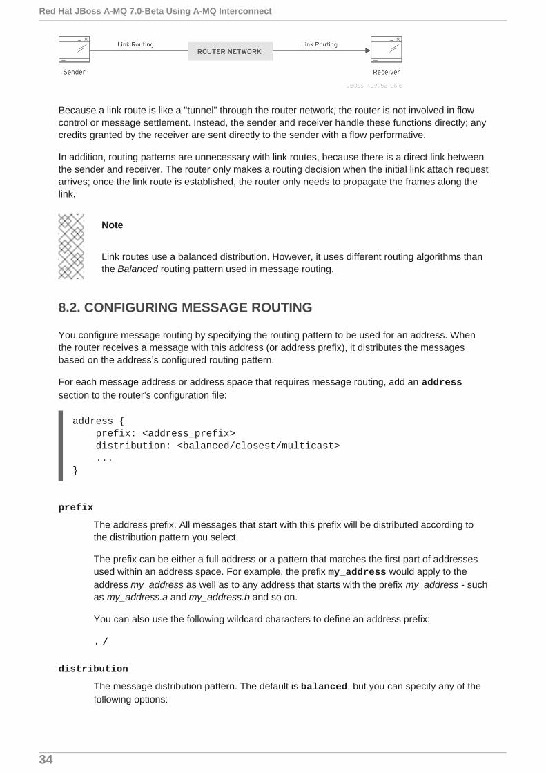
Because a link route is like a "tunnel" through the router network, the router is not involved in flowcontrol or message settlement. Instead, the sender and receiver handle these functions directly; anycredits granted by the receiver are sent directly to the sender with a flow performative.
In addition, routing patterns are unnecessary with link routes, because there is a direct link betweenthe sender and receiver. The router only makes a routing decision when the initial link attach requestarrives; once the link route is established, the router only needs to propagate the frames along thelink.
Note
Link routes use a balanced distribution. However, it uses different routing algorithms thanthe Balanced routing pattern used in message routing.
8.2. CONFIGURING MESSAGE ROUTING
You configure message routing by specifying the routing pattern to be used for an address. Whenthe router receives a message with this address (or address prefix), it distributes the messagesbased on the address’s configured routing pattern.
For each message address or address space that requires message routing, add an addresssection to the router’s configuration file:
address { prefix: <address_prefix> distribution: <balanced/closest/multicast> ...}
prefix
The address prefix. All messages that start with this prefix will be distributed according tothe distribution pattern you select.
The prefix can be either a full address or a pattern that matches the first part of addressesused within an address space. For example, the prefix my_address would apply to theaddress my_address as well as to any address that starts with the prefix my_address - suchas my_address.a and my_address.b and so on.
You can also use the following wildcard characters to define an address prefix:
. /
distribution
The message distribution pattern. The default is balanced, but you can specify any of thefollowing options:
Red Hat JBoss A-MQ 7.0-Beta Using A-MQ Interconnect
34
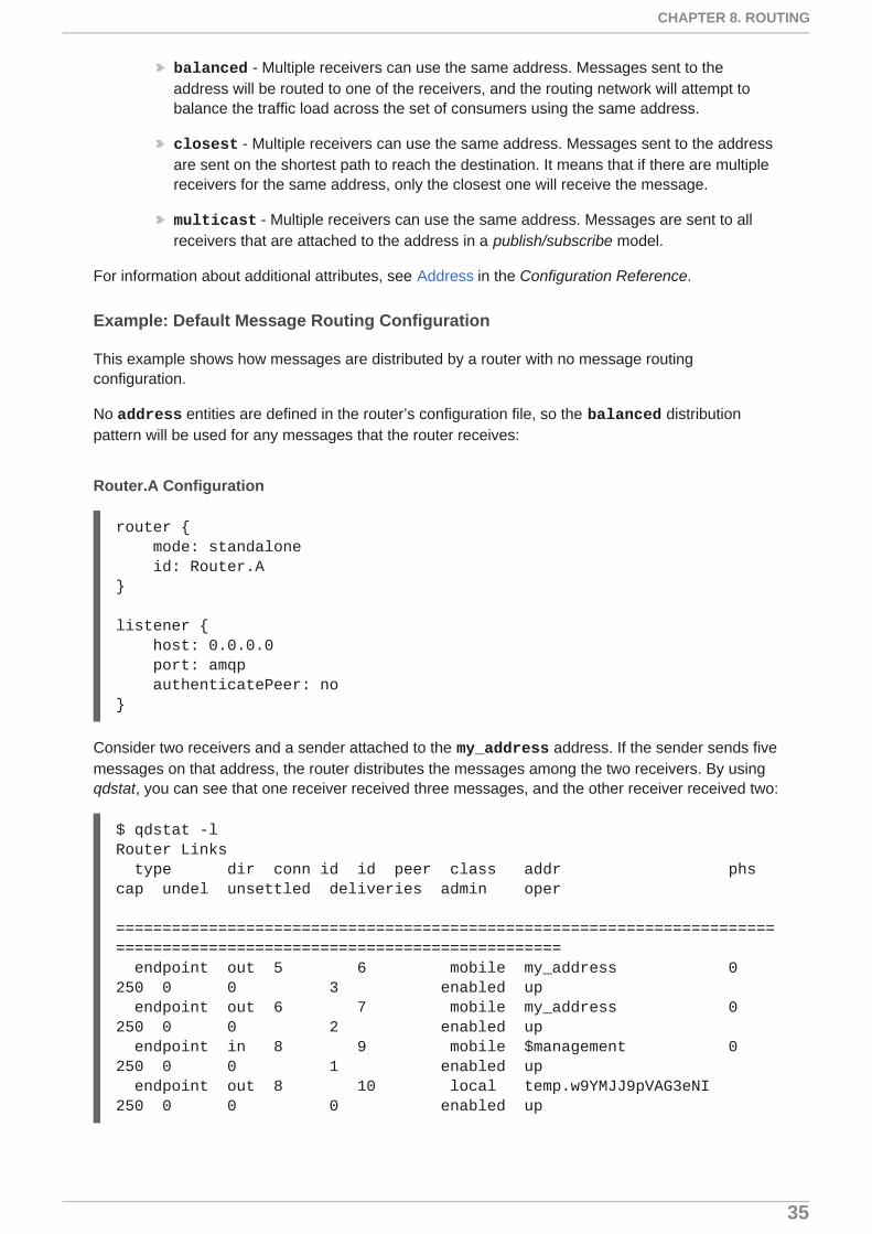
balanced - Multiple receivers can use the same address. Messages sent to theaddress will be routed to one of the receivers, and the routing network will attempt tobalance the traffic load across the set of consumers using the same address.
closest - Multiple receivers can use the same address. Messages sent to the addressare sent on the shortest path to reach the destination. It means that if there are multiplereceivers for the same address, only the closest one will receive the message.
multicast - Multiple receivers can use the same address. Messages are sent to allreceivers that are attached to the address in a publish/subscribe model.
For information about additional attributes, see Address in the Configuration Reference.
Example: Default Message Routing Configuration
This example shows how messages are distributed by a router with no message routingconfiguration.
No address entities are defined in the router’s configuration file, so the balanced distributionpattern will be used for any messages that the router receives:
Router.A Configuration
router { mode: standalone id: Router.A}
listener { host: 0.0.0.0 port: amqp authenticatePeer: no}
Consider two receivers and a sender attached to the my_address address. If the sender sends fivemessages on that address, the router distributes the messages among the two receivers. By usingqdstat, you can see that one receiver received three messages, and the other receiver received two:
$ qdstat -lRouter Links type dir conn id id peer class addr phs cap undel unsettled deliveries admin oper ======================================================================================================================= endpoint out 5 6 mobile my_address 0 250 0 0 3 enabled up endpoint out 6 7 mobile my_address 0 250 0 0 2 enabled up endpoint in 8 9 mobile $management 0 250 0 0 1 enabled up endpoint out 8 10 local temp.w9YMJJ9pVAG3eNI 250 0 0 0 enabled up
CHAPTER 8. ROUTING
35

Note
The router has two links attached on my_address for the two receivers that are waitingfor other messages. The link for the sender is not shown, because after sending themessages, it closes the connection.
Example: Message Routing Configuration with Multicast Distribution
This example shows how messages are distributed from a router configured to use the multicastdistribution for all messages sent to the my_address address.
The router’s configuration file contains an address entity:
A Router Configured for Multicast Distribution
address { prefix: my_address distribution: multicast}
In this case, when the sender sends five messages to my_address, all messages are distributed toboth receivers due to the multicast distribution pattern:
$ qdstat -lRouter Links type dir conn id id peer class addr phs cap undel unsettled deliveries admin oper ======================================================================================================================= endpoint out 1 2 mobile my_address 0 250 0 0 5 enabled up endpoint out 2 3 mobile my_address 0 250 0 0 5 enabled up endpoint in 4 5 mobile $management 0 250 0 0 1 enabled up endpoint out 4 6 local temp.IEyay0MFFPhmHh1 250 0 0 0 enabled up
Example: Message Routing Configuration with Closest Distribution
This example shows how messages are distributed in a network with two routers using the closest distribution pattern for all messages sent to the my_address address.
The first router, Router.A, is connected to the other router, Router.B. A receiver is attached toRouter.A on the my_address address. In addition, a sender is also attached to the router:
Router.A Configuration
router {
mode: interior
id: Router.A
1
Red Hat JBoss A-MQ 7.0-Beta Using A-MQ Interconnect
36

}
listener {
host: 0.0.0.0 port: 5672 authenticatePeer: no}
connector {
name: INTER_ROUTER host: 127.0.0.1 port: 5001 role: inter-router}
address {
prefix: my_address distribution: closest}
The router works in interior mode, because it is part of a router network.
The router listens for client traffic on port 5672.
The router’s connection to Router.B, which is the next hop in the network.
All messages with the my_address address will be distributed using the closest pattern.
Router.B is also connected to Router.A. A receiver is attached to Router.B on the my_addressaddress:
Router.B Configuration
router {
mode: interior id: Router.B}
listener {
host: 0.0.0.0 port: 5001
2
3
4
1
2
3
4
1
2
CHAPTER 8. ROUTING
37

authenticatePeer: no role: inter-router}
listener {
host: 0.0.0.0 port: 55672 authenticatePeer: no}
Like Router.A, Router.B works in interior mode.
Router.B listens on port 5001 for incoming connections from Router.A.
Router.B listens for client traffic on port 55672.
If the sender connected to Router.A sends five messages, all five of the messages would bereceived by the receiver connected to Router.A, because it is the closest receiver:
$ qdstat -l -r Router.ARouter Links type dir conn id id peer class addr phs cap undel unsettled deliveries admin oper ============================================================================================================================= router-control in 1 2 250 0 0 101 enabled up router-control out 1 3 local qdhello 250 0 0 101 enabled up inter-router in 1 4 250 0 0 0 enabled up inter-router out 1 5 250 0 0 0 enabled up endpoint out 2 6 mobile my_address 0 250 0 0 5 enabled up endpoint in 5 10 mobile $management 0 250 0 0 1 enabled up endpoint out 5 11 local temp.0kMX1jRjSFG2RsY 250 0 0 0 enabled up
No messages are delivered to the receiver connected to Router.B, because it is farther from thesender than the receiver connected to Router.A:
$ qdstat -l -r Router.BRouter Links
3
1
2
3
Red Hat JBoss A-MQ 7.0-Beta Using A-MQ Interconnect
38

type dir conn id id peer class addr phs cap undel unsettled deliveries admin oper ============================================================================================================================= router-control out 1 1 local qdhello 250 0 0 107 enabled up router-control in 1 2 250 0 0 104 enabled up inter-router out 1 3 250 0 0 0 enabled up inter-router in 1 4 250 0 0 0 enabled up endpoint out 2 5 mobile my_address 0 250 0 0 0 enabled up endpoint in 4 8 mobile $management 0 250 0 0 1 enabled up endpoint out 4 9 local temp.oISCehCM_8IqgdL 250 0 0 0 enabled up
If you were to change the distribution attribute to a different distribution pattern, you would seemessages delivered to Router.B. With a balanced pattern, some of the messages would bedelivered to Router.A, and the others would be delivered to Router.B. With a multicast pattern,both routers would receive all five messages.
8.3. CONFIGURING LINK ROUTING
Link routes establish a link between a sender and a receiver that travels through a router. You canconfigure inward and outward link routes to enable the router to receive link attaches from clientsand to send them to a particular destination.
With link routing, client traffic is handled on the broker, not the router. Clients have a direct linkthrough the router to a broker’s queue. Therefore, each client is a separate producer or consumer.
To configure a link route, in the router’s configuration file, do the following:
1. Add a linkRoute section for the incoming link route:
linkRoute { prefix: <address_prefix> connection: <listener_name> dir: in ...}
prefix
The address prefix. All messages that start with this prefix will be distributed alongthe link route.
The prefix can be either a full address or a pattern that matches the first part ofaddresses used within an address space. For example, the prefix my_addresswould apply to the address my_address as well as to any address that starts withthe prefix my_address - such as my_address.a and my_address.b and so on.
CHAPTER 8. ROUTING
39

You can also use the following wildcard characters to define an address prefix:
. /
connection
The name of the listener entity that the link route should use to establish theconnection with clients.
dir
Use in to configure this link route as the incoming route.
For information about additional attributes, see LinkRoute in the Configuration Reference.
2. Add another linkRoute section for the outgoing link route:
linkRoute { prefix: <address_prefix> connection: <connector_name> dir: out ...}
prefix
The address prefix. All messages that start with this prefix will be distributed alongthe link route.
connection
The name of the connector entity that the link route should use to establish theconnection with clients.
dir
Use out to configure this link route as the outgoing route.
For information about additional attributes, see LinkRoute in the Configuration Reference.
Example: Configuring a Link Route Through a Router
In this example, the router is connected to a broker, and it provides a link route to a queue on thebroker. The link route enables senders and receivers to send and receive messages from thebroker’s queue by connecting to the router.
To provide a link route to and from the broker’s queue, the router is configured as follows:
Router Configuration File
router { mode: standalone id: Router.A}
listener { host: 0.0.0.0
Red Hat JBoss A-MQ 7.0-Beta Using A-MQ Interconnect
40

port: 6000 authenticatePeer: no}
connector { name: BROKER addr: 127.0.0.1 port: 5672 role: route-container}
linkRoute { prefix: my_queue connection: BROKER dir: in}
linkRoute { prefix: my_queue connection: BROKER dir: out}
How Clients Receive Messages Through the Link Route
Receivers connect to the router through the listener connection and request messages from my_queue. The router then propagates the attach link directly to my_queue through the outgoing linkRoute and connector entities, and the receivers are able to receive the messages on thequeue as if the router was not in the middle.
How Clients Send Messages Through the Link Route
Senders also connect to the router using the listener connection. After connecting, they can sendmessages directly to my_queue using the incoming linkRoute entity.
8.4. CONFIGURING WAYPOINTS AND AUTOLINKS
Autolinks enable the router to actively attach a link to a node on an external AMQP container. Youuse them to route messages through a queue on a broker.
With autolinks, client traffic is handled on the router, not the broker. Clients attach their links to therouter, and then the router uses internal autolinks to connect to a queue on a broker. Therefore, thequeue will always have a single producer and a single consumer regardless of how many clients areattached to the router.
To configure waypoints and autolinks, in the router’s configuration file, do the following:
1. Add an address section for the address for which you want messages to be routed througha broker queue:
address { prefix: <address_prefix> waypoint: yes}
CHAPTER 8. ROUTING
41

prefix
The address prefix. All messages that start with this prefix will be routed based onthe configured autolinks.
The prefix can be either a full address or a pattern that matches the first part ofaddresses used within an address space. For example, the prefix my_addresswould apply to the address my_address as well as to any address that starts withthe prefix my_address - such as my_address.a and my_address.b and so on.
You can also use the following wildcard characters to define an address prefix:
. /
waypoint
Set this attribute to yes so that the router handles messages in this address spaceas a waypoint. These messages will be routed based on the autolinks youconfigure.
2. Add an incoming autoLink section to enable incoming messages from a queue:
autoLink { addr: <address> connection: <connection_name> dir: in ...}
addr
The address of the node on which the autolink should be created and attached.Typically, this would be a queue on a broker.
connection
The name of the connector or listener entity that should be used establish theconnection between the router and the external container that hosts the address.
dir
Use in to configure this autolink as the incoming link.
For information about additional attributes, see AutoLink in the Configuration_Reference.
3. Add an outgoing autoLink section to enable outgoing messages from a queue:
autoLink { addr: <address> connection: <connection_name> dir: out ...}
addr
Red Hat JBoss A-MQ 7.0-Beta Using A-MQ Interconnect
42

The address of the node on which the autolink should be created and attached.Typically, this would be a queue on a broker.
connection
The name of the connector or listener entity that should be used to establishthe connection between the router and the external container that hosts theaddress.
dir
Use out to configure this autolink as the outgoing link.
For information about additional attributes, see AutoLink in the Configuration_Reference.
Example: Using Autolinks to Provide Access to a Queue Through a Router
In this example, the router is connected to a broker, and it provides access to a queue on the broker.The autolink enables senders and receivers to access the broker’s queue by connecting to therouter.
To provide an autolink to and from the broker’s queue, the router is configured as follows:
Router Configuration File
router { mode: standalone id: Router.A}
listener {
host: 0.0.0.0 port: 6000 authenticatePeer: no}
connector {
name: BROKER addr: 127.0.0.1 port: 5672 role: route-container}
address {
prefix: my_queue waypoint: yes}
autoLink {
addr: my_queue connection: BROKER dir: in}
autoLink {
1
2
3
4
5
CHAPTER 8. ROUTING
43

addr: my_queue connection: BROKER dir: out}
The incoming connection. Receivers can connect to the router using this connection.
The outgoing connection. The router connects to the broker using this connection.
All messages with the address prefix my_queue will be handled as waypoints through theconfigured autolinks.
The incoming autolink from the broker to the router.
The outgoing autolink from the router to the broker.
How Clients Receive Messages
In this scenario, one or more receivers can connect to the router (on port 6000) asking formessages from the address my_queue. The router then uses the corresponding outgoing autolink toget messages from the queue and route them to the receiver.
Even if multiple receivers are attached to the router, there will always be just a single consumer forthe my_queue queue. This is because only the autolink is attached to the queue, and the routerroutes the messages from the queue to the receiver links.
How Clients Send Messages
Senders can send messages to the queue through the router using the corresponding autolink withthe in direction. Even if there are multiple senders, the queue will always have just a singleproducer.
With this router configuration, two links are established for the my_queue address. These are thetwo autolinks to the queue on the broker (one in each direction):
$ qdstat -l -r Router.ARouter Links type dir conn id id peer class addr phs cap undel unsettled deliveries admin oper
1
2
3
4
5
Red Hat JBoss A-MQ 7.0-Beta Using A-MQ Interconnect
44

======================================================================================================================= endpoint in 1 4 mobile my_queue 1 250 0 0 0 enabled up endpoint out 1 5 mobile my_queue 0 250 0 0 0 enabled up endpoint in 2 6 mobile $management 0 250 0 0 1 enabled up endpoint out 2 7 local temp.0KCwmAWv38lhAuB 250 0 0 0 enabled up
After starting two receivers connected to the router and attached to the my_queue address, twolinks are added with the out direction (from router to receivers):
$ qdstat -l -r Router.ARouter Links type dir conn id id peer class addr phs cap undel unsettled deliveries admin oper ======================================================================================================================= endpoint in 1 4 mobile my_queue 1 250 0 0 0 enabled up endpoint out 1 5 mobile my_queue 0 250 0 0 0 enabled up endpoint out 3 8 mobile my_queue 1 250 0 0 0 enabled up endpoint out 5 11 mobile my_queue 1 250 0 0 0 enabled up endpoint in 6 12 mobile $management 0 250 0 0 1 enabled up endpoint out 6 13 local temp.YEJJVklip0M9wOT 250 0 0 0 enabled up
Now, the sender connected to Router.A sends five messages. These messages are delivered to thequeue on the broker through the out autolink, and then distributed from the queue through the inautolink. Not all messages are delivered to both receivers, but are instead distributed across them ina competing consumers method using the two out autolinks established from the router to thereceivers:
$ qdstat -l -r Router.ARouter Links type dir conn id id peer class addr phs cap undel unsettled deliveries admin oper ======================================================================================================================= endpoint in 1 4 mobile my_queue 1 250 0 0 5 enabled up endpoint out 1 5 mobile my_queue 0 250 0 0 5 enabled up endpoint out 3 8 mobile my_queue 1 250 0 0 3 enabled up endpoint out 5 11 mobile my_queue 1 250 0 0 2 enabled up
CHAPTER 8. ROUTING
45

endpoint in 8 15 mobile $management 0 250 0 0 1 enabled up endpoint out 8 16 local temp.SVAfZtwKjQdcSTX 250 0 0 0 enabled up
Red Hat JBoss A-MQ 7.0-Beta Using A-MQ Interconnect
46

CHAPTER 9. LOGGING
Logging enables you to monitor the state of A-MQ Interconnect by accessing important informationsuch as how the router is configured and any error conditions that you must resolve.
A-MQ Interconnect consists of internal modules that provide important information about the router.For each module, you can specify logging levels, the format of the log file, and the location to whichthe logs should be written.
To configure logging:
1. Configure default logging to set the defaults.
2. Configure any individual logging modules for which you don’t want to use the defaultsettings.
9.1. LOGGING MODULES YOU CAN CONFIGURE
Before configuring logging, you should understand which modules can be logged and the type ofinformation each module provides.
The following table describes each logging module:
Module Description
DEFAULT The default module. You can configure this module to apply defaults toall of the other logging modules.
ROUTER Information and statistics about the local router. This includes how therouter connects to other routers in the network, and information about theremote destinations that are directly reachable from the router (linkroutes, waypoints, autolinks, and so on).
ROUTER_CORE The local router’s operations on active connections and links. Thisoperations related to opened and closed connections, messages sent,deliveries, and flow control.
ROUTER_HELLO The Hello protocol used by interior routers to exchange Hello messages,which include information about the router’s ID and a list of its reachableneighbors (the other routers with which this router has bidirectionalconnectivity).
The logs for this module are helpful for monitoring or resolving issues inthe network topology, and for determining to which other routers a routeris connected, and the hop-cost for each of those connections.
CHAPTER 9. LOGGING
47

ROUTER_LS The link-state information between routers, including RouterAdvertisement (RA), Link State Request (LSR), and Link State Update(LSU) messages.
Periodically, each router sends an LSR to the other routers and receivesan LSU with the requested information. Exchanging the aboveinformation, each router can compute the next hops in the topology, andthe related costs.
ROUTER_MA Monitors the exchange of mobile address information between routers,including Mobile Address Request (MAR) and Mobile Address Update(MAU) messages exchanged between routers. You can use this log tomonitor the state of mobile addresses attached to each router.
MESSAGE AMQP messages sent and received by the router, including informationabout the address, body, and link. You can use this log to find high-levelinformation about messages on a particular router.
SERVER Information about how the router is listening for and connecting to othercontainers in the network (such as clients, routers, and brokers). Thisincludes the state of AMQP messages sent and received by the broker(open, begin, attach, transfer, flow, and so on), and the related content ofthose messages.
AGENT Configuration changes made by either editing the router’s configurationfile or using qdmanage.
CONTAINER Information about the nodes related to the router. This includes only theAMQP relay node.
ERROR Detailed information about error conditions encountered duringexecution.
POLICY Information about policies that have been configured for the router.
Module Description
9.2. CONFIGURING DEFAULT LOGGING
Red Hat JBoss A-MQ 7.0-Beta Using A-MQ Interconnect
48

Configuring default logging enables you to set logging defaults. The settings you configure apply toall modules. However, you can configure additional log entities to override these defaults.
To configure default logging to provide general information, warnings, and errors for all loggingmodules, in the router’s configuration file, add a log section:
log { module: DEFAULT enable: <logging_level> timestamp: yes ...}
module
Specify DEFAULT.
enable
The logging level. You can specify any of the following levels (from lowest to highest):
trace - provides the most information, but significantly affects system performance
debug - useful for debugging, but affects system performance
info - provides general information without affecting system performance
notice - provides general information, but is less verbose than info
warning - provides information about issues you should be aware of, but which are noterrors
error - error conditions that you should address
critical - critical system issues that you must address immediately
To specify multiple levels, use a comma-separated list. You can also use + to specify alevel and all levels above it. For example, trace,debug,warning+ enables trace, debug,warning, error, and critical levels. For default logging, you should typically use the info+ or notice+ level. These levels will provide general information, warnings, and errors for allmodules without affecting the performance of A-MQ Interconnect.
timestamp
Set this to yes to include the timestamp in all logs.
For information about additional log attributes, see Log in the Configuration Reference.
9.3. CONFIGURING LOGGING MODULES
To configure logging for a module that should not follow the default logging configuration, in therouter’s configuration file, add a log section:
log { module: <module_name> enable: <logging_level> ...
CHAPTER 9. LOGGING
49

}
module
The name of the module for which you are configuring logging. For a list of valid modules,see Logging Modules You Can Configure.
enable
The logging level. You can specify any of the following levels (from lowest to highest):
trace - provides the most information, but significantly affects system performance
debug - useful for debugging, but affects system performance
info - provides general information without affecting system performance
notice - provides general information, but is less verbose than info
warning - provides information about issues you should be aware of, but which are noterrors
error - error conditions that you should address
critical - critical system issues that you must address immediately
To specify multiple levels, use a comma-separated list. You can also use + to specify alevel and all levels above it. For example, trace,debug,warning+ enables trace, debug,warning, error, and critical levels.
For information about additional log attributes, see Log in the Configuration Reference.
9.4. USING A-MQ INTERCONNECT LOGS
After configuring logging modules, you can use the logs to monitor A-MQ Interconnect and finduseful information.
9.4.1. Scenario for Log Examples
The log examples are based on the following configuration:
Router.A is listening for client connections and is connected to a broker and to Router.B.
Router.B is listening for connections from clients and other routers (in this case, Router.A).
Router.C is listening for connections from clients and other routers (in this case Router.B).
A broker for hosting queues.
Router.A Configuration
Router.A is configured with listener and connector entities, a mobile address for my_address, a linkroute for the queue my_queue on the broker, and a waypoint (with related autolinks in bothdirections) for the queue my_queue_wp on the broker.
router {
Red Hat JBoss A-MQ 7.0-Beta Using A-MQ Interconnect
50

mode: interior id: Router.A}
listener { host: 0.0.0.0 port: 5673 authenticatePeer: no}
connector { name: INTER_ROUTER host: 127.0.0.1 port: 5001 role: inter-router}
connector { name: BROKER host: 127.0.0.1 port: 5672 role: route-container}
address { prefix: my_address distribution: closest}
linkRoute { prefix: my_queue dir: in connection: BROKER}
linkRoute { prefix: my_queue dir: out connection: BROKER}
address { prefix: my_queue_wp waypoint: yes}
autoLink { addr: my_queue_wp dir: in connection: BROKER}
autoLink {
CHAPTER 9. LOGGING
51

addr: my_queue_wp dir: out connection: BROKER}
Router.B Configuration
Router.B is configured with listener and connector entities, with a waypoint for the queue my_queue_wp on the broker.
router { mode: interior id: Router.B}
listener { host: 0.0.0.0 port: 5001 authenticatePeer: no role: inter-router}
listener { host: 0.0.0.0 port: 55672 authenticatePeer: no}
connector { name: INTER_ROUTER host: 127.0.0.1 port: 5002 role: inter-router}
address { prefix: my_queue_wp waypoint: yes}
Router.C Configuration
Router.C is configured with listener entities, with a waypoint for the queue my_queue_qp on thebroker.
router { mode: interior id: Router.C}
listener { host: 0.0.0.0 port: 5002 authenticatePeer: no role: inter-router
Red Hat JBoss A-MQ 7.0-Beta Using A-MQ Interconnect
52
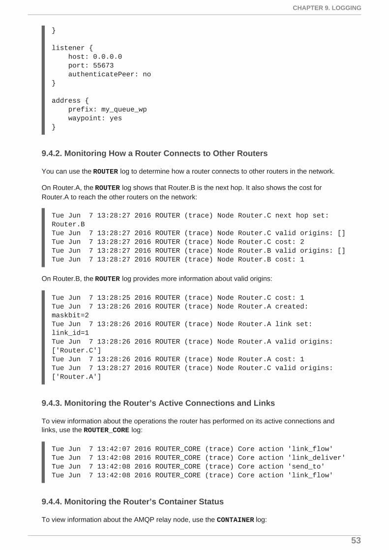
}
listener { host: 0.0.0.0 port: 55673 authenticatePeer: no}
address { prefix: my_queue_wp waypoint: yes}
9.4.2. Monitoring How a Router Connects to Other Routers
You can use the ROUTER log to determine how a router connects to other routers in the network.
On Router.A, the ROUTER log shows that Router.B is the next hop. It also shows the cost forRouter.A to reach the other routers on the network:
Tue Jun 7 13:28:27 2016 ROUTER (trace) Node Router.C next hop set: Router.BTue Jun 7 13:28:27 2016 ROUTER (trace) Node Router.C valid origins: []Tue Jun 7 13:28:27 2016 ROUTER (trace) Node Router.C cost: 2Tue Jun 7 13:28:27 2016 ROUTER (trace) Node Router.B valid origins: []Tue Jun 7 13:28:27 2016 ROUTER (trace) Node Router.B cost: 1
On Router.B, the ROUTER log provides more information about valid origins:
Tue Jun 7 13:28:25 2016 ROUTER (trace) Node Router.C cost: 1Tue Jun 7 13:28:26 2016 ROUTER (trace) Node Router.A created: maskbit=2Tue Jun 7 13:28:26 2016 ROUTER (trace) Node Router.A link set: link_id=1Tue Jun 7 13:28:26 2016 ROUTER (trace) Node Router.A valid origins: ['Router.C']Tue Jun 7 13:28:26 2016 ROUTER (trace) Node Router.A cost: 1Tue Jun 7 13:28:27 2016 ROUTER (trace) Node Router.C valid origins: ['Router.A']
9.4.3. Monitoring the Router’s Active Connections and Links
To view information about the operations the router has performed on its active connections andlinks, use the ROUTER_CORE log:
Tue Jun 7 13:42:07 2016 ROUTER_CORE (trace) Core action 'link_flow'Tue Jun 7 13:42:08 2016 ROUTER_CORE (trace) Core action 'link_deliver'Tue Jun 7 13:42:08 2016 ROUTER_CORE (trace) Core action 'send_to'Tue Jun 7 13:42:08 2016 ROUTER_CORE (trace) Core action 'link_flow'
9.4.4. Monitoring the Router’s Container Status
To view information about the AMQP relay node, use the CONTAINER log:
CHAPTER 9. LOGGING
53

Tue Jun 7 14:46:18 2016 CONTAINER (trace) Container InitializedTue Jun 7 14:46:18 2016 CONTAINER (trace) Node Type Registered - routerTue Jun 7 14:46:18 2016 CONTAINER (trace) Node of type 'router' installed as default node
9.4.5. Monitoring Low-Level Information about Messages Sent and ReceivedBy the Broker
To view detailed information about how the router is listening for and connecting to the other routersand broker in the network, use the SERVER log. In this case, the log shows details about how therouter handled a link attachment:
Tue Jun 7 14:39:52 2016 SERVER (trace) [2]: <- AMQPTue Jun 7 14:39:52 2016 SERVER (trace) [1]: <- AMQPTue Jun 7 14:39:52 2016 SERVER (trace) [1]:0 <- @open(16) [container-id="Router.B", max-frame-size=16384, channel-max=32767, idle-time-out=8000, offered-capabilities=:"ANONYMOUS-RELAY", properties={:product="qpid-dispatch-router", :version="0.6.0"}]Tue Jun 7 14:39:52 2016 SERVER (trace) [1]:0 -> @begin(17) [next-outgoing-id=0, incoming-window=15, outgoing-window=2147483647]Tue Jun 7 14:39:52 2016 SERVER (trace) [1]:RAW: "\x00\x00\x00\x1e\x02\x00\x00\x00\x00S\x11\xd0\x00\x00\x00\x0e\x00\x00\x00\x04@R\x00R\x0fp\x7f\xff\xff\xff"Tue Jun 7 14:39:52 2016 SERVER (trace) [1]:1 -> @begin(17) [next-outgoing-id=0, incoming-window=15, outgoing-window=2147483647]Tue Jun 7 14:39:52 2016 SERVER (trace) [1]:RAW: "\x00\x00\x00\x1e\x02\x00\x00\x01\x00S\x11\xd0\x00\x00\x00\x0e\x00\x00\x00\x04@R\x00R\x0fp\x7f\xff\xff\xff"Tue Jun 7 14:39:52 2016 SERVER (trace) [1]:0 -> @attach(18) [name="qdlink.uSSeXPSfTHhxo8d", handle=0, role=true, snd-settle-mode=2, rcv-settle-mode=0, source=@source(40) [durable=0, expiry-policy=:"link-detach", timeout=0, dynamic=false, capabilities=:"qd.router"], target=@target(41) [durable=0, expiry-policy=:"link-detach", timeout=0, dynamic=false, capabilities=:"qd.router"], initial-delivery-count=0]Tue Jun 7 14:39:52 2016 SERVER (trace) [1]:RAW: "\x00\x00\x00\x91\x02\x00\x00\x00\x00S\x12\xd0\x00\x00\x00\x81\x00\x00\x00\x0a\xa1\x16qdlink.uSSeXPSfTHhxo8dR\x00AP\x02P\x00\x00S(\xd0\x00\x00\x00'\x00\x00\x00\x0b@R\x00\xa3\x0blink-detachR\x00B@@@@@\xa3\x09qd.router\x00S)\xd0\x00\x00\x00#\x00\x00\x00\x07@R\x00\xa3\x0blink-detachR\x00B@\xa3\x09qd.router@@R\x00"
9.4.6. Monitoring the Router Topology
To view which routers are connected to this router, as well as the routers connected to them, usethe ROUTER_HELLO log.
On Router.A, the ROUTER_HELLO log shows that it is connected to Router.B, and that Router.B isconnected to Router.A and Router.C:
Tue Jun 7 13:50:21 2016 ROUTER_HELLO (trace) RCVD: HELLO(id=Router.B
area=0 inst=1465307413 seen=['Router.A', 'Router.C']) 1
Red Hat JBoss A-MQ 7.0-Beta Using A-MQ Interconnect
54

Tue Jun 7 13:50:21 2016 ROUTER_HELLO (trace) SENT: HELLO(id=Router.A
area=0 inst=1465307416 seen=['Router.B'])
Tue Jun 7 13:50:22 2016 ROUTER_HELLO (trace) RCVD: HELLO(id=Router.B area=0 inst=1465307413 seen=['Router.A', 'Router.C'])Tue Jun 7 13:50:22 2016 ROUTER_HELLO (trace) SENT: HELLO(id=Router.A area=0 inst=1465307416 seen=['Router.B'])
Router.A received a Hello message from Router.B, which can see Router.A and Router.C.
Router.A sent a Hello message to Router.B, which is the only router it can see.
On Router.B, the ROUTER_HELLO log shows the same router topology from a different perspective:
Tue Jun 7 13:50:18 2016 ROUTER_HELLO (trace) SENT: HELLO(id=Router.B
area=0 inst=1465307413 seen=['Router.A', 'Router.C'])
Tue Jun 7 13:50:18 2016 ROUTER_HELLO (trace) RCVD: HELLO(id=Router.A
area=0 inst=1465307416 seen=['Router.B'])
Tue Jun 7 13:50:19 2016 ROUTER_HELLO (trace) RCVD: HELLO(id=Router.C
area=0 inst=1465307411 seen=['Router.B'])
Router.B sent a Hello message to Router.A and Router.C.
Router.B received a Hello message from Router.A, which can only see Router.B.
Router.B received a Hello message from Router.C, which can only see Router.B.
9.4.7. Monitoring the Router Toplogy with Related Costs
To view the entire router topology with next hops for each router, and the associated hop-costs, usethe ROUTER_LS log:
Tue Jun 7 14:10:02 2016 ROUTER_LS (trace) SENT: LSR(id=Router.A area=0) to: Router.C //Tue Jun 7 14:10:02 2016 ROUTER_LS (trace) SENT: LSR(id=Router.A area=0) to: Router.B //Tue Jun 7 14:10:02 2016 ROUTER_LS (trace) SENT: RA(id=Router.A area=0
inst=1465308600 ls_seq=1 mobile_seq=1)
2
1
2
1
2
3
1
2
3
1
CHAPTER 9. LOGGING
55

Tue Jun 7 14:10:02 2016 ROUTER_LS (trace) RCVD: LSU(id=Router.B area=0 inst=1465308595 ls_seq=2 ls=LS(id=Router.B area=0 ls_seq=2 peers=
{'Router.A': 1L, 'Router.C': 1L}))
Tue Jun 7 14:10:02 2016 ROUTER_LS (trace) RCVD: LSR(id=Router.B area=0)Tue Jun 7 14:10:02 2016 ROUTER_LS (trace) SENT: LSU(id=Router.A area=0 inst=1465308600 ls_seq=1 ls=LS(id=Router.A area=0 ls_seq=1 peers={'Router.B': 1}))Tue Jun 7 14:10:02 2016 ROUTER_LS (trace) RCVD: RA(id=Router.C area=0 inst=1465308592 ls_seq=1 mobile_seq=0)Tue Jun 7 14:10:02 2016 ROUTER_LS (trace) SENT: LSR(id=Router.A area=0) to: Router.CTue Jun 7 14:10:02 2016 ROUTER_LS (trace) RCVD: LSR(id=Router.C
area=0)
Tue Jun 7 14:10:02 2016 ROUTER_LS (trace) SENT: LSU(id=Router.A area=0 // inst=1465308600 ls_seq=1 ls=LS(id=Router.A area=0 ls_seq=1 peers={'Router.B': 1}))Tue Jun 7 14:10:02 2016 ROUTER_LS (trace) RCVD: LSU(id=Router.C area=0 inst=1465308592 ls_seq=1 ls=LS(id=Router.C area=0 ls_seq=1 peers=
{'Router.B': 1L}))
Tue Jun 7 14:10:03 2016 ROUTER_LS (trace) Computed next hops:
{'Router.C': 'Router.B', 'Router.B': 'Router.B'}
Tue Jun 7 14:10:03 2016 ROUTER_LS (trace) Computed costs: {'Router.C': 2L, 'Router.B': 1}Tue Jun 7 14:10:03 2016 ROUTER_LS (trace) Computed valid origins: {'Router.C': [], 'Router.B': []}
Router.A sent LSR requests and an RA advertisement to the other routers on the network.
Router.A received an LSU from Router.B, which has two peers: Router.A, and Router.C(with a cost of 1).
Router.A received an LSR from both Router.B and Router.C, and the replied with an LSU.
Router.A received an LSU from Router.C, which only has one peer: Router.B (with a cost of1).
After the LSR and LSU messages are exchanged, Router.A computed the router topologywith the related costs.
2
3
4
5
1
2
3
4
5
Red Hat JBoss A-MQ 7.0-Beta Using A-MQ Interconnect
56

9.4.8. Monitoring Mobile Addresses
To view the mobile addresses attached to each router in the network, use the ROUTER_MA log:
Tue Jun 7 14:27:20 2016 ROUTER_MA (trace) SENT: MAU(id=Router.A area=0 mobile_seq=1 add=['Cmy_queue', 'Dmy_queue', 'M0my_queue_wp'] del=[])
Tue Jun 7 14:27:21 2016 ROUTER_MA (trace) RCVD: MAR(id=Router.C area=0
have_seq=0)
Tue Jun 7 14:27:21 2016 ROUTER_MA (trace) SENT: MAU(id=Router.A area=0 mobile_seq=1 add=['Cmy_queue', 'Dmy_queue', 'M0my_queue_wp'] del=[])Tue Jun 7 14:27:22 2016 ROUTER_MA (trace) RCVD: MAR(id=Router.B area=0
have_seq=0)
Tue Jun 7 14:27:22 2016 ROUTER_MA (trace) SENT: MAU(id=Router.A area=0 mobile_seq=1 add=['Cmy_queue', 'Dmy_queue', 'M0my_queue_wp'] del=[])Tue Jun 7 14:27:39 2016 ROUTER_MA (trace) RCVD: MAU(id=Router.C area=0
mobile_seq=1 add=['M0my_test'] del=[])
Tue Jun 7 14:27:51 2016 ROUTER_MA (trace) RCVD: MAU(id=Router.C area=0
mobile_seq=2 add=[] del=['M0my_test'])
Router.A sent MAU messages to the other routers in the network to notify them about theaddresses added for my_queue and my_queue_wp.
Router.A received a MAR message in response from Router.C.
Router.A received another MAR message in response from Router.B.
Router.C sent a MAU message to notify the other routers that it added and address for my_test.
Router.C sent another MAU message to notify the other routers that it deleted the addressfor my_test (because the receiver is detached).
9.4.9. Viewing Information about Messages
To view information about the messages a router sent and received, use the MESSAGE log.
1
2
3
4
5
1
2
3
4
5
CHAPTER 9. LOGGING
57

Router.A has sent and received some messages related to the Hello protocol, and sent andreceived some other messages on a link for a mobile address:
Tue Jun 7 14:36:54 2016 MESSAGE (trace) Sending Message{to='amqp:/_topo/0/Router.B/qdrouter' body='\d1\00\00\00\1b\00\00\00\04\a1\02id\a1\08R'} on link qdlink.p9XmBm19uDqx50RTue Jun 7 14:36:54 2016 MESSAGE (trace) Received Message{to='amqp:/_topo/0/Router.A/qdrouter' body='\d1\00\00\00\8e\00\00\00\a1\06ls_se'} on link qdlink.phMsJOq7YaFsGAGTue Jun 7 14:36:54 2016 MESSAGE (trace) Received Message{ body='\d1\00\00\00\10\00\00\00\02\a1\08seque'} on link qdlink.FYHqBX+TtwXZHfVTue Jun 7 14:36:54 2016 MESSAGE (trace) Sending Message{ body='\d1\00\00\00\10\00\00\00\02\a1\08seque'} on link qdlink.yU1tnPs5KbMlieMTue Jun 7 14:36:54 2016 MESSAGE (trace) Sending Message{to='amqp:/_local/qdhello' body='\d1\00\00\00G\00\00\00\08\a1\04seen\d0'} on link qdlink.p9XmBm19uDqx50RTue Jun 7 14:36:54 2016 MESSAGE (trace) Sending Message{to='amqp:/_topo/0/Router.C/qdrouter' body='\d1\00\00\00\1b\00\00\00\04\a1\02id\a1\08R'} on link qdlink.p9XmBm19uDqx50R
9.4.10. Monitoring Router Configuration History
To view a history of all configuration changes made to a router, use the AGENT log.
On Router.A, address, linkRoute, and autoLink entities were added to the router’sconfiguration file. When the router was started, the AGENT module applied these changes, and theyare now viewable in the log:
Tue Jun 7 15:07:32 2016 AGENT (debug) Add entity: ConnectorEntity(addr=127.0.0.1, allowRedirect=True, cost=1, host=127.0.0.1, identity=connector/127.0.0.1:5672:BROKER, idleTimeoutSeconds=16, maxFrameSize=65536, name=BROKER, port=5672, role=route-container, stripAnnotations=both, type=org.apache.qpid.dispatch.connector, verifyHostName=True)Tue Jun 7 15:07:32 2016 AGENT (debug) Add entity: RouterConfigAddressEntity(distribution=closest, identity=router.config.address/0, name=router.config.address/0, prefix=my_address, type=org.apache.qpid.dispatch.router.config.address, waypoint=False)Tue Jun 7 15:07:32 2016 AGENT (debug) Add entity: RouterConfigAddressEntity(distribution=balanced, identity=router.config.address/1, name=router.config.address/1, prefix=my_queue_wp, type=org.apache.qpid.dispatch.router.config.address, waypoint=True)Tue Jun 7 15:07:32 2016 AGENT (debug) Add entity: RouterConfigLinkrouteEntity(connection=BROKER, dir=in, distribution=linkBalanced, identity=router.config.linkRoute/0, name=router.config.linkRoute/0, prefix=my_queue, type=org.apache.qpid.dispatch.router.config.linkRoute)
Red Hat JBoss A-MQ 7.0-Beta Using A-MQ Interconnect
58

Tue Jun 7 15:07:32 2016 AGENT (debug) Add entity: RouterConfigLinkrouteEntity(connection=BROKER, dir=out, distribution=linkBalanced, identity=router.config.linkRoute/1, name=router.config.linkRoute/1, prefix=my_queue, type=org.apache.qpid.dispatch.router.config.linkRoute)Tue Jun 7 15:07:32 2016 AGENT (debug) Add entity: RouterConfigAutolinkEntity(addr=my_queue_wp, connection=BROKER, dir=in, identity=router.config.autoLink/0, name=router.config.autoLink/0, type=org.apache.qpid.dispatch.router.config.autoLink)Tue Jun 7 15:07:32 2016 AGENT (debug) Add entity: RouterConfigAutolinkEntity(addr=my_queue_wp, connection=BROKER, dir=out, identity=router.config.autoLink/1, name=router.config.autoLink/1, type=org.apache.qpid.dispatch.router.config.autoLink)
9.4.11. Diagnosing Error Conditions
To diagnose internal errors on a router, use the ERROR log.
Router.A failed to start when an incorrect path was specified for the router’s configuration file:
# qdrouterd --conf xxxWed Jun 15 09:53:28 2016 ERROR (error) Python: Exception: Cannot load configuration file xxx: [Errno 2] No such file or directory: 'xxx'Wed Jun 15 09:53:28 2016 ERROR (error) Traceback (most recent call last): File "/usr/lib/qpid-dispatch/python/qpid_dispatch_internal/management/config.py", line 155, in configure_dispatch config = Config(filename) File "/usr/lib/qpid-dispatch/python/qpid_dispatch_internal/management/config.py", line 41, in __init__ self.load(filename, raw_json) File "/usr/lib/qpid-dispatch/python/qpid_dispatch_internal/management/config.py", line 123, in load with open(source) as f:Exception: Cannot load configuration file xxx: [Errno 2] No such file or directory: 'xxx'
Wed Jun 15 09:53:28 2016 MAIN (critical) Router start-up failed: Python: Exception: Cannot load configuration file xxx: [Errno 2] No such file or directory: 'xxx'qdrouterd: Python: Exception: Cannot load configuration file xxx: [Errno 2] No such file or directory: 'xxx'
9.4.12. Viewing Router Policy Configuration Information
To view information about any policies that have been configured for the router, use the Policylog.
Router.A has no limits on maximum connections, and the default application policy is disabled:
CHAPTER 9. LOGGING
59

Tue Jun 7 15:07:32 2016 POLICY (info) Policy configured maximumConnections: 0, policyFolder: '', access rules enabled: 'false'Tue Jun 7 15:07:32 2016 POLICY (info) Policy fallback defaultApplication is disabled
Red Hat JBoss A-MQ 7.0-Beta Using A-MQ Interconnect
60

CHAPTER 10. MONITORING A-MQ INTERCONNECT USINGQDSTAT
You can use qdstat to view the status of routers on your router network. For example, you can viewinformation about the attached links and configured addresses, available connections, and nodes inthe router network.
10.1. SYNTAX FOR USING QDSTAT
You can use qdstat with the following syntax:
$ qdstat <option> [<connection_options>] [<secure_connection_options>]
This specifies:
An <option> for the type of information to view.
One or more optional <connection_options> to specify a router for which to view theinformation.
If you do not specify a connection option, qdstat connects to the router listening on localhost andthe default AMQP port (5672).
The <secure_connection_options> if the router for which you want to view information onlyaccepts secure connections.
10.2. CONNECTION OPTIONS
By default, qdstat displays information for a router listening on localhost on the default AMQP port(5672). However, you can specify additional connection options if you want to view information for adifferent router on the router network.
Connection Option Description
-b <URL> The URL of the router for which you want to view information. The URLshould include the router’s address and port.
-r <router_ID> The ID of the router for which you want to view information.
-t <seconds> The maximum number of seconds to wait for the connection. The defaultis 5.
10.3. SECURE CONNECTION OPTIONS
If you want to view information for a router that only accepts secure connections over SSL, you canspecify the following secure connection options:
CHAPTER 10. MONITORING A-MQ INTERCONNECT USING QDSTAT
61

Connection Option Description
--ssl-certificate=<path_to_file>
The path to the client SSL certificate. The certificate must be in PEMformat.
--ssl-key=<path_to_file>
The path to the client SSL private key. The key must be in PEM format.
--ssl-trustfile=<path_to_file>
The path to the Trusted Certificate Authority Database file. The file mustbe in PEM format.
--ssl-password=<password>
The certificate password. If you do not use this option, you will beprompted for the password.
10.4. BASIC COMMANDS
You can use the following commands to view information about qdstat:
To view… Use this command…
Help for qdstat.$ qdstat -h
The version of qdstat.$ qdstat --version
10.5. COMMANDS FOR MONITORING A-MQ INTERCONNECT
You can use these commands to view information for one or more routers on the router network.
10.5.1. Viewing General Statistics for a Router
Use the following command:
$ qdstat -g [<connection_options>]
This command displays the following fields:
Mode
The working mode of the router. Possible values include interior and standalone.
Red Hat JBoss A-MQ 7.0-Beta Using A-MQ Interconnect
62

Router ID
The router’s unique ID.
Example
$ qdstat -gRouter Statistics attr value ========================= Mode interior Area 0 Router Id Router.A
10.5.2. Viewing a List of Connections to a Router
You can view:
Connections from clients (sender/receiver)
Connections from and to other routers in the network
Connections to other containers (such as brokers)
Connections from the tool itself
Use this command:
$ qdstat -c [<connection_options>]
This command displays the following fields:
Id
The connection’s unique ID.
host
The hostname or IP address of the remotely-connected AMQP container.
container
The container name of the remotely-connected AMQP container.
role
The connection’s role. Connections can have the following roles:
normal - normal connection from a client to a router
inter-router - connection between routers to form a network
route-container - connection to or from a broker or other host to receive link-routesand waypoints
dir
The direction in which the connection was established. Possible directions include:
in - connection initiated by the remote container
CHAPTER 10. MONITORING A-MQ INTERCONNECT USING QDSTAT
63

in - connection initiated by the remote container
out - connection initiated by this router
security
The security or encryption method, if any, used for this connection.
authentication
The authentication method and user ID of the connection’s authenticated user.
Example
In this example, two clients are connected to Router.A. Router.A is connected to Router.B and abroker.
Viewing the connections on Router.A displays the following:
$ qdstat -cConnections Id host container role dir security authentication ========================================================================================================================== 2 127.0.0.1:5672
route-container out no-security anonymous-user
10 127.0.0.1:5001 Router.B
inter-router out no-security anonymous-user
12 localhost.localdomain:42972 161211fe-ba9e-4726-9996-52d6962d1276
normal in no-security anonymous-user
14 localhost.localdomain:42980 a35fcc78-63d9-4bed-b57c-053969c38fda
normal in no-security anonymous-user
15 localhost.localdomain:42982 0a03aa5b-7c45-4500-8b38-db81d01ce651
normal in no-security anonymous-user
This connection shows that Router.A is connected to a broker, because the role is route-container, and the dir is out.
Router.A is also connected to another router on the network (the role is inter-router),establishing an output connection (the dir is out).
These connections show that two clients are connected to Router.A, because the role is normal, and the dir is in.
1
2
3
4
5
1
2
3 4
Red Hat JBoss A-MQ 7.0-Beta Using A-MQ Interconnect
64

The connection from qdstat to Router.A. This is the connection that qdstat uses to queryRouter.A and display the command output.
Router.A is connected to Router.B. Viewing the connections on Router.B displays the following:
$ qdstat -c -r Router.BConnections Id host container role dir security authentication ============================================================================================ 1 localhost.localdomain:51848 Router.A inter-router in no-
security anonymous-user
This connection shows that Router.B is connected to Router.A through an incomingconnection (the role is inter-router and the dir is in). There is not a connection fromqdstat to Router.B, because the command was run from Router.A and forwarded toRouter.B.
10.5.3. Viewing AMQP Links Attached to a Router
You can view a list of AMQP links attached to the router from clients (sender/receiver), from or toother routers into the network, to other containers (for example, brokers), and from the tool itself.
Use this command:
$ qdstat -l [<connection_options>]
This command displays the following fields:
type
The type of link. Types include:
router-control - An inter-router link reserved for control messages exchangedbetween routers.
inter-router - An inter-router link used for normal message-routed deliveries.
endpoint - A normal link to an external endpoint container.
dir
The direction that messages flow on the link. Links can be one of the following:
in - The link delivers incoming messages to the router.
out - The link delivers outgoing messages from the router.
5
1
1
CHAPTER 10. MONITORING A-MQ INTERCONNECT USING QDSTAT
65

conn id
The unique identifier of the connection over which this link is attached.
id
The unique identifier of this link.
peer
For link-routed links, the unique identifier of the peer link. In link routing, an inbound link ispaired with an outbound link.
class
The class of the address bound to the link. Addresses can have the following classes:
local - The address that is local to this router (temporary).
topo - A topological address used for router control messages.
router - A summary router address used to route messages to a remote router’s localaddresses.
mobile - A mobile address for an attached consumer or producer.
link-in - The address match for incoming routed links.
link-out - The address match for outgoing routed-links.
addr
The address bound to the link.
phs
The phase of the address bound to the link.
cap
The capacity, in deliveries, of the link.
undel
The number of undelivered messages stored on the link’s FIFO.
unsettled
The number of unsettled deliveries being tracked by the link.
deliveries
The total number of deliveries that have transited this link.
admin
The administrative status of the link. A link can be:
enabled - The link is enabled for normal operation.
disabled - The link is disabled, and should be either quiescing or stopped.
Red Hat JBoss A-MQ 7.0-Beta Using A-MQ Interconnect
66

oper
The operational status of the link. A link can be:
up - The link is operational.
down - The link is not attached.
quiescing - The link is in the process of quiescing.
idle - The link has completed quiescing and is idle.
name - The link name (only shown if the -v option is provided).
Example
In this example, Router.A is connected to both Router.B and a broker. A link route is configured forthe my_queue queue and waypoint (with autolinks), and for the my_queue_wp queue on the broker.In addition, there is a receiver connected to my_address (message routing based), another to my_queue, and the a third one to my_queue_wp.
In this configuration, the router uses only one connection to the broker for both the waypoints(related to my_queue_wp) and the link route (related to my_queue).
Viewing the links displays the following:
$ qdstat -lRouter Links type dir conn id id peer class addr phs cap undel unsettled deliveries admin oper ============================================================================================================================= router-control in 2 7
250 0 0 2876 enabled up
router-control out 2 8 local qdhello 250 0 0 2716 enabled up inter-router in 2 9 250 0 0 1 enabled up inter-router out 2 10 250 0 0 1 enabled up endpoint in 1 11 mobile my_queue_wp
1 250 0 0 3 enabled up
endpoint out 1 12 mobile my_queue_wp 0 250 0 0 3 enabled up endpoint out 4 15 mobile my_address
0 250 0 0 0 enabled up
endpoint out 6 18 19
250 0 0 1 enabled up
endpoint in 1 19 18
0 0 0 1 enabled up
endpoint out 19 40 mobile my_queue_wp
1 250 0 0 1 enabled up
1
2
3
4
5
6
CHAPTER 10. MONITORING A-MQ INTERCONNECT USING QDSTAT
67

endpoint in 24 48 mobile $management 0 250 0 0 1 enabled up endpoint out 24 49 local temp.mx5HxzUe2Eddw_s 250 0 0 0 enabled up
The conn id 2 connection has four links (in both directions) for inter-routercommunications with Router.B, such as control messages and normal message-routeddeliveries.
There are two autolinks (conn id 1) for the waypoint for my_queue_wp. There is anincoming (id 11) and outgoing (id 12) link to the broker, and another out link (id 40) tothe receiver.
A mobile link for my_address. The dir is out related to the receiver attached to it.
The out link from the router to the receiver for my_queue. This enables the router to delivermessages to the receiver.
The in link to the router for my_queue. This enables the router to get messages from my_queue so that they can be sent to the receiver on the out link.
The remaining links are related to the $management address and are used by qdstat toreceive the information that is displayed by this command.
10.5.4. Viewing Known Routers on a Network
You can view a list of known routers to see the router topology:
$ qdstat -n [<connection_options>]
This command displays the following fields:
router-id
The router’s ID.
1
2
3
4
5
6
Red Hat JBoss A-MQ 7.0-Beta Using A-MQ Interconnect
68

next-hop
If this router is not a neighbor, this field identifies the next-hop neighbor used to reach thisroute.
link
The ID of the link to the neighbor router.
cost
The topology cost to this remote router (with -v option only).
neighbors
A list of neighbor routers (the router’s link-state). This field is available only if you use the -voption.
valid-origins
The list of origin routers for which the best path to the listed router passes through thisrouter (self). This field is available only if you use the -v option.
Example
In this example, Router.A is connected to Router.B, which is connected to Router.C.
View the router topology on Router.A shows the following:
$ qdstat -n -r Router.ARouters in the Network router-id next-hop link cost neighbors valid-origins ==========================================================================
Router.A (self) - ['Router.B'] []
Router.B - 0 1 ['Router.A', 'Router.C'] []
Router.C Router.B - 2 ['Router.B'] []
Router.A has one neighbor: Router.B.
Router.B is connected to Router.A and Router.C over link 0. The cost for Router.A toreach Router.B is 1, because the two routers are connected directly.
Router.C is connected to Router.B, but not to Router.A. The cost for Router.A to reachRouter.C is 2, because messages would have to pass through Router.B as the next-hop.
1
2
3
1
2
3
CHAPTER 10. MONITORING A-MQ INTERCONNECT USING QDSTAT
69

Router.B shows a different view of the router topology:
$ qdstat -n -v -r Router.BRouters in the Network router-id next-hop link cost neighbors valid-origins ========================================================================== Router.A - 0 1 ['Router.B'] ['Router.C'] Router.B (self) - ['Router.A', 'Router.C'] [] Router.C - 1 1 ['Router.B'] ['Router.A']
The neighbors list is the same when viewed on Router.B. However, from the perspective ofRouter.B, the destinations on Router.A and Router.C both have a cost of 1. This is becauseRouter.B is connected to Router.A and Router.C through links.
The valid-origins field shows that starting from Router.C, Router.B has the best path to reachRouter.A. Likewise, starting from Router.A, Router.B has the best path to reach Router.C.
Finally, Router.C shows the following details about the router topology:
$ qdstat -n -v -r Router.CRouters in the Network router-id next-hop link cost neighbors valid-origins ========================================================================== Router.A Router.B - 2 ['Router.B'] [] Router.B - 0 1 ['Router.A', 'Router.C'] [] Router.C (self) - ['Router.B'] []
Due to a symmetric topology, Router.C’s perspective of the topology is very similar to Router.A’s.The primary difference is the cost: the cost to reach Router.B is 1, because the two routers areconnected. However, the cost to reach Router.A is 2, because the messages would have to passthrough Router.B as the next-hop.
10.5.5. Viewing Addresses Known to a Router
You can view message-routed and link-routed addresses known to a router:
$ qdstat -a [<connection_options>]
This command displays the following fields:
class
One of the following address classes:
local - An address that is local to this router (that is, temporary).
topo - A topological address used for router control messages.
Red Hat JBoss A-MQ 7.0-Beta Using A-MQ Interconnect
70

router - A summary router address used to route messages to a remote router’s localaddresses.
mobile - A mobile address for an attached consumer or producer.
link-in - An address match for incoming routed links.
link-out - Address match for outgoing routed links.
addr
The address name.
phs
For mobile addresses, this is the phase of the address. Direct addresses have a phase 0only. Waypoint addresses have multiple phases, typically 0 and 1.
distrib
One of the following distribution methods used for this address:
multicast - A copy of each message is delivered once to each consumer for theaddress.
closest - Each message is delivered to only one consumer for the address. Theclosest (lowest cost) consumer will be chosen. If there are multiple lowest-costconsumers, deliveries will be spread across those consumers.
balanced - Each message is delivered to only one consumer for the address. Theconsumer with the fewest outstanding (unsettled) deliveries will be chosen. The cost ofthe route to the consumer is a threshold for delivery (for example, higher costconsumers will only receive deliveries if closer consumers are backed up).
flood - Used only for router-control traffic. This method is multicast without theprevention of duplicate deliveries.
linkBalanced - Used only for autolinks. This method is similar to balanced, but usesa different algorithm.
in-proc
The number of in-process consumers for this address.
local
The number of local (on this router) consumers for this address.
remote
The number of remote routers that have at least one consumer for this address.
cntnr
The number of locally-attached containers that are destinations for link routes on thisaddress.
in
The number of deliveries for this address that entered the network on this router.
CHAPTER 10. MONITORING A-MQ INTERCONNECT USING QDSTAT
71

out
The number of deliveries for this address that exited the network on this router.
thru
The number of deliveries for this address that were forwarded to other routers.
to-proc
The number of deliveries for this address that were delivered to an in-process consumer.
from-proc
The number of deliveries for this address that were received from an in-process producer.
Example
In this example, Router.A is connected to both Router.B and a broker. The broker has two queues: * my_queue (with a link route on Router.A) * my_queue_wp (with a waypoint and autolinks configuredon Router.A)
In addition, there are three receivers: one connected to my_address for message routing, anotherconnected to my_queue, and the last one connected to my_queue_wp.
Viewing the addresses displays the following information:
$ qdstat -aRouter Addresses class addr phs distrib in-proc local remote cntnr in out thru to-proc from-proc ====================================================================================================================== local $_management_internal closest 1 0 0 0 0 0 0 0 0 local $displayname closest 1 0 0 0 0 0 0 0 0 mobile $management 0 closest 1 0 0 0 8 0 0 8 0 local $management closest 1 0 0 0 0 0 0 0 0 router Router.B closest 0 0
1 0 0 0 5 0 5
mobile my_address 0 closest 0 1
0 0 1 1 0 0 0
link-in my_queue linkBalanced 0 0
0 1 0 0 0 0 0
link-out my_queue linkBalanced 0 0 0 1 0 0 0 0 0 mobile my_queue_wp 1 balanced 0 1
0 0 1 1 0 0 0
mobile my_queue_wp 0 balanced 0 1 0 0 1 1 0 0 0 local qdhello flood 1 1
0 0 0 0 0 741 706
local qdrouter flood 1 0
1
2
3
4
5
Red Hat JBoss A-MQ 7.0-Beta Using A-MQ Interconnect
72

0 0 0 0 0 4 0 topo qdrouter flood 1 0 1 0 0 0 27 28 28 local qdrouter.ma multicast 1 0 0 0 0 0 0 1 0 topo qdrouter.ma multicast 1 0 1 0 0 0 2 0 3 local temp.IJSoXoY_lX0TiDE closest 0 1 0 0 0 0 0 0 0
An address related to Router.B with a remote at 1. This is the consumer from Router.B.
The my_address address has one local consumer, which is related to the single receiverattached on that address. The in and out fields are both 1, which means that one messagehas traveled through this address using the closest distribution method.
The incoming link route for the my_queue address. This address has one locally-attachedcontainer (cntnr) as a destination (in this case, the broker). The following entry is theoutgoing link for the same address.
The incoming autolink for the my_queue_wp address and configured waypoint. There is onelocal consumer (local) for the attached receiver. The following entry is the outgoingautolink for the same address. A single message has traveled through the autolinks.
The qdhello, qdrouter, and qdrouter.ma addresses are used to periodically updatethe network topology and deliver router control messages. These updates are madeautomatically through the inter-router protocol, and are based on all of the messages therouters have exchanged. In this case, the distribution method (distrib) for each addressis either flood or multicast to ensure the control messages reach all of the routers in thenetwork.
10.5.6. Viewing a Router’s Autolinks
You can view a list of the autolinks that are associated with waypoint addresses for a node onanother container (such as a broker):
$ qdstat --autolinks [<connection_options>]
1
2
3
4
5
CHAPTER 10. MONITORING A-MQ INTERCONNECT USING QDSTAT
73

This command displays the following fields:
addr
The address of the autolink.
dir
The direction of message flow for the autolink:
in - Messages flow in from the route-container to the router network.
out - Messages flow out to the route-container from the router network.
phs
The phase of the address for this autolink.
link
The ID of the link managed by this autolink.
status
The operational status of this autolink:
inactive - There is no connected container for this autolink.
attaching - The link is in the process of attaching to the container.
failed - The link-attach failed.
active - The link is operational.
quiescing - The link is quiescing.
idle - The link is idle.
Example
In this example, a router is connected to a broker. The broker has a queue called my_queue_wp, towhich the router is configured with a waypoint and autolinks.
Viewing the autolinks displays the following:
$ qdstat --autolinksAutoLinks addr dir phs link status lastErr ==============================================
my_queue_wp in 1 4 active
my_queue_wp out 0 5 active
The incoming autolink from my_queue_wp. As indicated by the status field, the link isactive, because the broker is running and the connection for the link is already established(as indicated by the link field).
1
2
1
Red Hat JBoss A-MQ 7.0-Beta Using A-MQ Interconnect
74

The outgoing autlink to my_queue_wp. Like the incoming link, it is active and has anestablished connection.
10.5.7. Viewing the Status of a Router’s Link Routes
You can view the status of each incoming and outgoing link route:
$ qdstat --linkroutes [<connection_options>]
This command displays the following fields:
prefix
The address prefix of the link route.
dir
The direction of the link (from the router’s perspective).
distrib
The distribution method used for routed links. This value should always be linkBalanced,because it is the only supported distribution for routed links.
status
The operational status of the link route:
active - The route is currently routing attaches.
inactive - The route is inactive, because a local destination is not connected.
Example
In this example, a router is connected to a broker. The router is configured with a link route to the my_queue queue on the broker.
Viewing the link routes displays the following:
$ qdstat --linkroutesLink Routes prefix dir distrib status =====================================
my_queue in linkBalanced active
my_queue out linkBalanced active
The incoming link route from my_queue to the router. This route is currently active,because the broker is running.
2
1
2
1
CHAPTER 10. MONITORING A-MQ INTERCONNECT USING QDSTAT
75

The outgoing link from the router to my_queue. This route is also currently active.
10.5.8. Viewing Memory Consumption Information
If you need to perform debugging or tracing for a router, you can view information about its memoryconsumption:
$ qdstat -m [<connection_options>]
This command displays information about allocated objects, their size, and their usage byapplication threads:
Types type size batch thread-max total in-threads rebal-in rebal-out =========================================================================================== qd_bitmask_t 24 64 128 64 64 0 0 qd_buffer_t 536 16 32 80 80 0 0 qd_composed_field_t 64 64 128 256 256 0 0 qd_composite_t 112 64 128 320 320 0 0 qd_connection_t 224 64 128 128 128 0 0 qd_connector_t 56 64 128 64 64 0 0 qd_deferred_call_t 32 64 128 192 192 0 0 qd_field_iterator_t 128 64 128 192 192 0 0 qd_hash_handle_t 16 64 128 64 64 0 0 qd_hash_item_t 32 64 128 128 128 0 0 qd_hash_segment_t 24 64 128 64 64 0 0 qd_link_t 48 64 128 128 128 0 0 qd_listener_t 32 64 128 64 64 0 0 qd_log_entry_t 2,104 16 32 32 32 0 0 qd_management_context_t 56 64 128 64 64 0 0 qd_message_content_t 640 16 32 48 48 0 0 qd_message_t 128 64 128 320 320 0 0
2
Red Hat JBoss A-MQ 7.0-Beta Using A-MQ Interconnect
76

qd_node_t 56 64 128 64 64 0 0 qd_parsed_field_t 80 64 128 128 128 0 0 qd_timer_t 56 64 128 128 128 0 0 qd_work_item_t 24 64 128 256 256 0 0 qdpn_connector_t 600 16 32 32 32 0 0 qdpn_listener_t 48 64 128 64 64 0 0 qdr_action_t 160 64 128 256 256 0 0 qdr_address_t 264 16 32 16 16 0 0 qdr_conn_identifier_t 80 64 128 64 64 0 0 qdr_connection_ref_t 24 64 128 64 64 0 0 qdr_connection_t 216 64 128 192 192 0 0 qdr_connection_work_t 56 64 128 64 64 0 0 qdr_delivery_ref_t 24 64 128 64 64 0 0 qdr_delivery_t 136 64 128 192 192 0 0 qdr_error_t 24 64 128 128 128 0 0 qdr_field_t 40 64 128 192 192 0 0 qdr_general_work_t 64 64 128 64 64 0 0 qdr_link_ref_t 24 64 128 64 64 0 0 qdr_link_route_t 80 64 128 64 64 0 0 qdr_link_t 264 16 32 48 48 0 0 qdr_query_t 336 16 32 32 32 0 0 qdr_terminus_t 64 64 128 192 192 0 0
CHAPTER 10. MONITORING A-MQ INTERCONNECT USING QDSTAT
77

CHAPTER 11. MANAGING A-MQ INTERCONNECT USINGQDMANAGE
You can use qdmanage to view and modify the configuration of a running router at runtime.Specifically, qdmanage enables you to create, read, update, and delete the sections and attributesin the router’s configuration file without having to restart the router.
Note
The qdmanage tool implements the AMQP management specification, which means thatyou can use it with any standard AMQP-managed endpoint, not just with the A-MQInterconnect component.
11.1. SYNTAX FOR USING QDMANAGE
You can use qdmanage with the following syntax:
$ qdmanage [<connection_options>] <operation> [<options>]
This specifies:
One or more optional <connection_options> to specify the router on which to perform theoperation, or to supply security credentials if the router only accepts secure connections.
If you do not specify any connection options, qdmanage connects to the router listening onlocalhost and the default AMQP port (5672).
The <operation> to perform on the router.
One or more optional <options> to specify a configuration entity on which to perform theoperation or how to format the command output.
When you enter a qdmanage command, it is executed as an AMQP management operationrequest, and then the response is returned as command output in JSON format.
For example, the following command executes a query operation on a router, and then returns theresponse in JSON format:
$ qdmanage query --type listener[ { "stripAnnotations": "both", "addr": "127.0.0.1", "requireSsl": false, "idleTimeoutSeconds": 16, "maxFrameSize": 16384, "requireEncryption": false, "host": "0.0.0.0", "cost": 1, "role": "normal", "authenticatePeer": false, "type": "org.apache.qpid.dispatch.listener", "port": "amqp",
Red Hat JBoss A-MQ 7.0-Beta Using A-MQ Interconnect
78

"identity": "listener/0.0.0.0:amqp", "name": "listener/0.0.0.0:amqp" }]
11.2. CONNECTION OPTIONS
By default, qdmanage operates on a router listening on localhost on the default AMQP port (5672).However, you can specify additional connection options if you want to view information for a differentrouter on the router network, or if you need to supply security credentials to connect to the router.
Connection Option Description
-b <URL> The URL of the router for which you want to perform an operation. TheURL should include the router’s address and port.
-r <router_ID> The ID of the router for which you want to perform an operation.
-t <seconds> The maximum number of seconds to wait for the connection. The defaultis 5.
--ssl-certificate=<path_to_file>
The path to the client SSL certificate. The certificate must be in PEMformat.
--ssl-key=<path_to_file>
The path to the client SSL private key. The key must be in PEM format.
--ssl-trustfile=<path_to_file>
The path to the Trusted Certificate Authority Database file. The file mustbe in PEM format.
--ssl-password=<password>
The certificate password. If you do not use this option, you will beprompted for the password.
11.3. MANAGEMENT OPERATIONS
You can perform the following management operations using the qdmanage tool:
CHAPTER 11. MANAGING A-MQ INTERCONNECT USING QDMANAGE
79

To… Use this operation…
View attributes for one ormore entities
query [<attr1> … ]
This operation displays the specified attribute or attributes for all entities.To specify the entities for which to view the attribute, use the --type, --name, or --identity options.
To view multiple attributes, separate the attributes with a space. If you donot specify any attributes, then all attributes for all entities are displayed.
Create a new entity with thespecified attributes
create [<attr1>=<value> … ]
To add multiple attributes for the entity, separate each attribute-value pairwith a space.
To create one or more entities using JSON format instead of a list ofattribute-value pairs, use the --stdin option.
View an entity’s attributes read
You must use the --name or --identity option to specify the entityfor which you want to view attributes.
Update an entity’s attributes update [<attr1>=<value> … ]
To update multiple attributes for the entity, separate each attribute-valuepair with a space.
To update one or more entities using JSON format instead of a list ofattribute-value pairs, use the --stdin option.
If an attribute name is listed with no value, the attribute will be deletedfrom the entity.
Delete an entity delete
You must use the --name or --identity option to specify the entityto delete.
View the operations for oneor more entity types
get-operations [<entity_type>]
If you do not specify any entity types, the operations are listed for allentity types.
View the available attributesfor an entity type
get-attributes [<entity_type>]
If you do not specify any entity types, the attributes are listed for all entitytypes.
Red Hat JBoss A-MQ 7.0-Beta Using A-MQ Interconnect
80

View the availableannotations for an entity type
get-annotations [<entity_type>]
If you do not specify any entity types, the annotations are listed for allentity types.
View a list of managementnodes connected to this one
get-mgmt-nodes
View the router configurationin JSON format
get-json-schema [<indentation>]
If you want formatted output, specify the number of characters ofindentation that should be used.
View recent log entries get-log [<indentation>]
If you want formatted output, specify the number of characters ofindentation that should be used.
To… Use this operation…
11.4. OPTIONS
You use options to specify the configuration entities on which to perform an operation. You can alsouse options to control how the command input and output is formatted.
Option Description
-h Display the help for using qdmanage.
--version Display the version of qdmanage.
--type=<type> The type of the entity on which to perform the operation.
--name=<name> The name of the entity on which to perform the operation.
--identity=<ID> The ID of the entity on which to perform the operation. This is thesystem-generated ID created automatically when the entity was created.You cannot change this value.
CHAPTER 11. MANAGING A-MQ INTERCONNECT USING QDMANAGE
81

--indent=<integer> The number of characters to indent the output. The default is 2. Tospecify no indentation, set this option to -1.
--stdin If the operation requires you to provide entity or attribute values, thisoption enables you to provide that information as a JSON map or list ofJSON maps. For example, if you are creating a new configuration entity, --stdin enables you to enter the entity’s name and attributes in JSONformat.
--body=<JSON_value> The JSON value to use as the body of a non-standard operation call.
--properties=<JSON_map>
The JSON map to use as properties for a non-standard operation call.
Option Description
11.5. COMMANDS FOR MANAGING A-MQ INTERCONNECT
You can use these commands to manage a router.
11.5.1. Viewing Configured Attributes
Use the following command:
$ qdmanage [connection_option] query [attr1 ...] [[--name <entity_name>] [--identity <entity_ID>] [--type <entity_type>]]
This command displays all of the specified attributes across all of the specified entities on the router.
For example, this command displays all attributes for listener entities on a router running onlocalhost and listening on the default AMQP port:
$ qdmanage query --type listener[ { "stripAnnotations": "both", "addr": "127.0.0.1", "requireSsl": false, "idleTimeoutSeconds": 16, "maxFrameSize": 16384, "requireEncryption": false, "host": "0.0.0.0", "cost": 1, "role": "normal", "authenticatePeer": false, "type": "org.apache.qpid.dispatch.listener",
Red Hat JBoss A-MQ 7.0-Beta Using A-MQ Interconnect
82

"port": "amqp", "identity": "listener/0.0.0.0:amqp", "name": "listener/0.0.0.0:amqp" }]
If you only wanted to view the roles and ports on which the router is listening for incomingconnections, you could use the following command:
$ qdmanage query port role --type listener[ { "role": "normal", "port": "5672" }, { "role": "inter-router", "port": "5001" }]
This query shows that there are two different listeners on the router: one for accepting normalcommunication from AMQP clients, and one for accepting connections from another router in thenetwork.
11.5.2. Creating Entities
You can create new entities in either of the following ways:
Specify a list of attribute-value pairs that describe the entity.
Provide a JSON map of attributes for each new entity that you want to create.
11.5.2.1. Creating a Single Entity Using Attribute-Value Pairs
Use the following command:
$ qdmanage [connection_options] create [<attr1>=<value> ...]
For example, the following command establishes a connection from the router to a broker, and thendisplays the new entity in JSON format:
$ qdmanage -b localhost:5673 create type=connector name=BROKER host=127.0.0.1 port=5672 role=route-container{ "verifyHostName": true, "stripAnnotations": "both", "name": "BROKER", "allowRedirect": true, "idleTimeoutSeconds": 16, "maxFrameSize": 65536, "host": "127.0.0.1", "cost": 1, "role": "route-container", "type": "org.apache.qpid.dispatch.connector",
CHAPTER 11. MANAGING A-MQ INTERCONNECT USING QDMANAGE
83

"port": "5672", "identity": "connector/127.0.0.1:5672:BROKER", "addr": "127.0.0.1"}
11.5.2.2. Creating Multiple Entities Using JSON Format
Use the following command:
$ qdmanage [connection_options] create --stdin[ {"<entity1_attr>":"<value>", ...}, {"<entity2_attr>":"<value>", ...}]
For example, the following command establishes a link route to a queue by creating an incomingand outgoing linkRoute entities:
$ qdmanage -b localhost:5673 create --stdin[ { "type":"linkRoute", "prefix":"my_queue", "connection":"BROKER", "dir":"in" }, { "type":"linkRoute", "prefix":"my_queue", "connection":"BROKER", "dir":"out" } ]
The command output shows the created entities and their attributes (both the attributes configuredby the command and the defaults):
[ { "name": null, "operStatus": "active", "prefix": "my_queue", "connection": "BROKER", "identity": "5", "distribution": "linkBalanced", "type": "org.apache.qpid.dispatch.router.config.linkRoute", "dir": "in", "containerId": null }, { "name": null, "operStatus": "active", "prefix": "my_queue", "connection": "BROKER", "identity": "6", "distribution": "linkBalanced", "type": "org.apache.qpid.dispatch.router.config.linkRoute", "dir": "out", "containerId": null }]
On the router, the log confirms the connection has been established with the broker, and that thelinks are active for the queue:
Wed Jun 8 13:15:15 2016 CONN_MGR (info) Configured Connector: 127.0.0.1:5672 proto=any role=route-containerWed Jun 8 13:18:01 2016 ROUTER_CORE (info) Link Route Activated '5' on
Red Hat JBoss A-MQ 7.0-Beta Using A-MQ Interconnect
84

connection BROKERWed Jun 8 13:18:01 2016 ROUTER_CORE (info) Link Route Activated '6' on connection BROKER
11.5.3. Viewing an Entity’s Attributes
Use the following command:
$ qdmanage [connection_options] read [[--name <entity_name>] [--identity <entity_ID>]]
For example, this command displays the attributes for a connector entity named BROKER:
$ qdmanage -b localhost:5673 read --name BROKER{ "verifyHostName": true, "stripAnnotations": "both", "name": "BROKER", "allowRedirect": true, "idleTimeoutSeconds": 16, "maxFrameSize": 65536, "host": "127.0.0.1", "cost": 1, "role": "route-container", "type": "org.apache.qpid.dispatch.connector", "port": "5672", "identity": "connector/127.0.0.1:5672:BROKER", "addr": "127.0.0.1"}
11.5.4. Updating Entities
You can update entities in either of the following ways:
Specify a list of attribute-value pairs that describe the entity.
Provide a JSON map of attributes for each new entity that you want to create.
In both cases, if you specify an attribute without a value, the attribute will be deleted.
11.5.4.1. Updating a Single Entity Using Attribute-Value Pairs
Use the following command to specify the new or updated attributes for the entity:
$ qdmanage [connection_options] update [<attr1>=<value> ...]
For example, this command changes the logging level for the ROUTER module, and then displays theupdated entity in JSON format:
$ qdmanage -b localhost:5673 update name=log/ROUTER enable=trace+{ "enable": "trace+", "type": "org.apache.qpid.dispatch.log", "identity": "log/ROUTER",
CHAPTER 11. MANAGING A-MQ INTERCONNECT USING QDMANAGE
85

"module": "ROUTER", "name": "log/ROUTER"}
11.5.4.2. Updating Multiple Entities Using JSON Format
Use the following command to specify the new or updated attributes for the entities:
$ qdmanage [connection_options] update --stdin[ {"<entity1_attr>":"<value>", ...}, {"<entity2_attr>":"<value>", ...}]
For example, this command changes the logging level for two modules:
$ qdmanage -b localhost:5673 update --stdin[{ "enable":"debug", "name":"log/ROUTER", "timestamp":"yes" }, { "enable":"debug", "name":"log/ROUTER_CORE", "timestamp":"yes" }]
The command output shows the updated entities and their attributes:
[ { "enable": "debug", "name": "log/ROUTER", "timestamp": true, "module": "ROUTER", "type": "org.apache.qpid.dispatch.log", "identity": "log/ROUTER" } { "enable": "debug", "name": "log/ROUTER_CORE", "timestamp": true, "module": "ROUTER_CORE", "type": "org.apache.qpid.dispatch.log", "identity": "log/ROUTER_CORE" }]
11.5.5. Deleting Entities
Use the following command:
$ qdmanage [connection_options] delete [--name <entity_name>] [--identity <entity_ID>]]
For example, this command deletes the configuration for a message address:
$ qdmanage -b localhost:5673 delete --name my_address_name
Command output is only displayed in the event of an error. For example:
$ qdmanage -b localhost:5673 delete --name wrong_address_nameNotFoundStatus: No entity with name='wrong_address_name'
Red Hat JBoss A-MQ 7.0-Beta Using A-MQ Interconnect
86

CHAPTER 12. MANAGING ROUTERS USING A-MQCONSOLE
The console is an HTML based website that displays information about an A-MQ Interconnectnetwork. In order to work, it requires an HTML web server that can serve static HTML, JavaScript,CSS files and images. The console only provides limited information about the clients that areattached to the router network and is therefore more appropriate for administrators needing to knowthe layout and health of the network itself.
12.1. INSTALLATION
See the A-MQ Interconnect release notes for information about installing the web console .war file.
In order to use the installed web console, there is the need for a websockets to TCP proxy asprerequisite. Its role is to listen for websocket traffic on a specific port and translating it to TCP trafficon another port. All the traffic in terms of requests and responses to/from the router from/to the webconsole are through this proxy. To install a websockets proxy, in this case named "websockify", thefollowing command can be executed :
# yum install python-websockify
After installation, the proxy can be manually started in the following way.
# websockify localhost:5673 localhost:20009
From the above, websockify starts to listen for websockets traffic on port 5673 and will proxy it toport 20009 (in this case on the same machine).
A router needs to have a listener on the proxied port. A sample configuration could be the following.
listener { name: proxy-listener role: normal host: 0.0.0.0 port: 20009 sasl-mechanisms: ANONYMOUS}
It is not mandatory but it is a good practice to have a listener on the router that is dedicated to theproxy in order to keep console management traffic separated from any clients that may connect tothat listener (so that the statistics do not get mixed together).
It is also possible to start the proxy program when a router starts. In this case the console entityneeds to be configured with following attributes :
listener : the name of the listener to use in order to communicate with the websockets to TCPproxy.
proxy : the name of the proxy program to start.
args : arguments list to pass to the proxy program.
Referring the previous listener entity, the related console entity could be configured in the followingway.
CHAPTER 11. MANAGING A-MQ INTERCONNECT USING QDMANAGE
87

console { listener: proxy-listener proxy: wobsockify args: $host:5673 $host:$port}
12.2. WEB CONSOLE PAGES
Following the main pages which enable the user to do all the possible operations on the routerthrough the web console.
12.2.1. Logging Into a Router Network
After installation, the console is available on http://[host] (on the default HTTP port 80) and thelanding page provides the login feature in order to access to the router on which the websocketproxy is configured. The needed parameters are the address and the related port of the websocketsto tcp proxy that is connected to a router in the network.
The Autostart checkbox, when checked, will automatically log in with the previous host:port the nexttime you start the console.
Figure 12.1. Login
12.2.2. Overview Page
The overview page shows information about routers, addresses and connections.
The "Routers" section provides all information about the routers in the network.
Figure 12.2. Routers Overview
Red Hat JBoss A-MQ 7.0-Beta Using A-MQ Interconnect
88

The "Addresses" section shows a list of addresses known to the router related to link routed andmessage routed address other than inter router communication addresses. It exposes someinformation from the command line tool qdstat launched with option -a.
Figure 12.3. Addresses Overview
The "Links" section provides a list of AMQP links attached to the router from clients(sender/receiver), from/to other routers into the network, to other containers (i.e. brokers) and fromthe tool itself. It exposes some information from the command line tool qdstat launched with option-l.
Figure 12.4. Links Overview
The "Connections" section provides a list of connections to the router from clients (sender/receiver),from/to other routers into the network and to other containers (i.e. brokers). It exposes someinformation from the command line tool qdstat launched with option -c.
Figure 12.5. Connections Overview
CHAPTER 12. MANAGING ROUTERS USING A-MQ CONSOLE
89

12.2.3. Topology Page
This page displays the router network in a graphical shape showing how the routers are connected.Clicking on each router, it is possible to have more information about it; the same is true clicking onthe arrow which defines a link between two routers.
Figure 12.6. Network Topology
12.2.4. Entities Page
This page displays detailed information about all the entities which define the configuration for eachrouter in the network like links, addresses, memory and so on.
Figure 12.7. Router Entities
Some attributes provides the possibility to draw their values in the chart page. These attributes havea chart icon and clicking on it, the related values will be plotted in a new chart on a dashboard.
12.3. OPERATIONS
The web console provides a lot of features in order to admin the routers in the network. Followingsome interesting operations that can be executed using the console and interacting with theunderlying routers.
Red Hat JBoss A-MQ 7.0-Beta Using A-MQ Interconnect
90

12.3.1. Drawing Data in Real Time
The are some attributes in some entities that can be drawn on charts which show data updating inreal time. These charts are displayed in the "Dashboard" section of the "hawtio" console. Of course,it is possible to create a dedicated dashboard for all the meaningful real time data that theadministrator want to see.
Each chart can be customized in terms of colors, duration and type : it can display the attributevalues or the rate.
For example, consider to have a receiver which is attached on address my_address on the router.In the "Entities" page, this address is shown as mobile address with all related attributes in the"router.address" topic on the left side.
Figure 12.8. Address View
In order to draw the delivery rate for this address on a chart, it is possible to click on the "chart" iconon the right side of a "drawable" attribute and in this case "Deliveries Ingress" and "DeliveriesEgress". Clicking on the "Add this chart to a dashboard" button, the web console redirects to the"Dashboard" page in order to add this chart to an existing dashboard or for creating a new one. Dothe same thing for both attributes.
Figure 12.9. Chart View
On the dashboard page, both the charts are displayed and clicking on the configuration button foreach chart, it is possible to change some properties like the "type" from "Value chart" to "Ratechart".
Figure 12.10. Changing Chart Type
CHAPTER 12. MANAGING ROUTERS USING A-MQ CONSOLE
91

Now, start a receiver attached to the my_address address in order to start receiving messages anda sender attached to the same address in order to send them. While the two peers are exchangingmessages through the router, the related charts are updating in real time showing the number ofmessages per second the router is transferring in ingress (from the sender) and egress (to thereceiver).
Figure 12.11. Charts on Dashboard
12.3.2. Configuring an Entity
The "Entities" page allows to update the current configuration for all the routers in the networkbecause for each entity it is possible to execute operations like "Create" and "Delete".
For example, in order to provide reliability, during the lifetime of the entire system, it could benecessary to add a connection from a router to a broker which is already reachable from anotherrouter having path redundancy feature.
The web console allows that through the "Entities" page. After selecting the router in the network,the "connector" item is available on the left side in order to show all the available connectors for thatrouter. The "Create" button allows to add a new connector with all needed information.
It is possible to specify a name for the connector, the IP address and the port of the broker that therouter should connect to.
Figure 12.12. Creating a Connector
Red Hat JBoss A-MQ 7.0-Beta Using A-MQ Interconnect
92

In the same way, using the "Delete" button, it is possible to delete a connector.
12.3.3. Adding a Router
Using the "Topology" page it is possible to see the current network topology with all routers andattached clients with links between them as well. It is also possible to add a router and configuring itwith a friendly user interface.
In order to do that, clicking with the right mouse button in an empty space shows the "Add a newrouter" item which places a new router symbol into the network. After that, clicking on each of theother routers, it creates new connections between them and the new router just added.
Figure 12.13. Adding a Router
On the left side, the "edit" button provides a rich interface useful for configuring and modifying all thedefault parameters of the router.
Figure 12.14. New Router Configuration
Finally, clicking on the "Download" button, it is possible to download the automatically generated
CHAPTER 12. MANAGING ROUTERS USING A-MQ CONSOLE
93

configuration file. This file can be used to start the router passing it as parameter with the --confoption.
12.3.4. Fetching Last Log
Sometimes it could be useful to fetch last router logs in order to see if the system is healthy or thereare some problem and the web console offers this feature through the "Entities" page.
From the "log" topic (on the left side), it is possible to select the log module for which we want to seethe log and then click on the "Fetch" button.
Figure 12.15. Fetching Last Log
Red Hat JBoss A-MQ 7.0-Beta Using A-MQ Interconnect
94

CHAPTER 13. RELIABILITY
In general, in a broker based architecture, the reliability feature is strictly related to the "store andforward" mechanism offered by each broker. Thanks to persistent journals, a broker can offer faulttolerance thus avoiding message loss; of course, it is not so true when messages are stored only ina volatile memory.
This is completely different using A-MQ Interconnect, because each router neither takes ownershipof messages nor stores them in a persistent storage. In this case, the reliability feature is offered bypath redundancy which provides the possibility to reach the destination on different paths throughthe router network. In normal conditions, the best path is always chosen in terms of lowest cost but,when one or more routers go down, the topology is revisited by all remained routers and new pathsare processed in order to reach always each destination. Of course, it means that the reliability isstrictly related to the network topology the user chooses for his solution.
Because a solution based on A-MQ Interconnect could be made not only by routers but by brokerstoo, the reliability is improved with persistent storage on them which add not only fault tolerance buttemporal decoupling as well; without "store and forward" feature offered by brokers, the temporaldecoupling is not possible only with routers and direct peers, both senders and receivers; thereceiver must be online at same time of the sender in order to receive messages.
13.1. PATH REDUNDANCY
Offering path redundancy means designing the network topology in a way that even when one ormore routers go down or even connections between them, each destination is always reachablefollowing alternate paths through the routers that are still part of the network.
Consider the following simple scenario :
a network with three routers "Router.A", "Router.B" and "Router.C".
the "Router.A" is connected to both "Router.B" and "Router.C".
the "Router.C is connected to the "Router.B".
all three routers listen for client connections.
a sender client connects to the "Router.A" in order to send messages to a receiver client.
a receiver client connects to the "Router.B" initially in order to receive messages from the senderpeer.
Figure 13.1. Path Redundancy Enabled Topology
CHAPTER 12. MANAGING ROUTERS USING A-MQ CONSOLE
95

The "Router.A" configuration is something like following.
router { mode: interior id: Router.A}
listener { host: 0.0.0.0 port: 6000 authenticatePeer: no}
connector { name: INTER_ROUTER_B addr: 127.0.0.1 port: 5001 role: inter-router}
connector { name: INTER_ROUTER_C addr: 127.0.0.1 port: 5002 role: inter-router}
There is only one listener in order to accept client connections and two connector entities forconnecting to the other two routers.
The "Router.B" configuration is the following.
router { mode: interior id: Router.B}
listener { addr: 0.0.0.0
Red Hat JBoss A-MQ 7.0-Beta Using A-MQ Interconnect
96

port: 5001 authenticatePeer: no role: inter-router}
listener { host: 0.0.0.0 port: 6001 authenticatePeer: no}
It has two listener entities in order to listen for connections from clients and from other routers in thenetwork (in this case from the "Router.A" and "Router.C").
Finally, quite similar is the "Router.C" configuration.
router { mode: interior id: Router.C}
listener { addr: 0.0.0.0 port: 5002 authenticatePeer: no role: inter-router}
listener { host: 0.0.0.0 port: 6002 authenticatePeer: no}
connector { name: INTER_ROUTER_B addr: 127.0.0.1 port: 5001 role: inter-router}
It has two listener entities in order to listen for connections from clients and from other routers in thenetwork (in this case from the "Router.A") and finally it has a connector (for connecting to the"Router.B")
Consider a sender client connected to "Router.A" and attached to my_address address which startto send messages (i.e. 10 messages) and a receiver client connected to the "Router.B" and attachedto the same address.
Starting the receiver, it waits for messages with no output on the console.
# python simple_recv.py -a localhost:6001/my_queue -m 10
Starting the sender, all the messages flow through "Router.A" and "Router.B" reaching the receiver;at this point the messages are all confirmed at sender side.
CHAPTER 13. RELIABILITY
97

# python simple_send.py -a localhost:6001/my_queue -m 10all messages confirmed
At same time, the receivers shows the messages received through the "Router.B".
{u'sequence': 1L}{u'sequence': 2L}{u'sequence': 3L}{u'sequence': 4L}{u'sequence': 5L}{u'sequence': 6L}{u'sequence': 7L}{u'sequence': 8L}{u'sequence': 9L}{u'sequence': 10L}
The path redundancy is provided by the other available path through the "Router.A", "Router.C" andthen "Router.B". It means that if the connection between "Router.A" and "Router.B" goes down, thealternative path is used to reach the receiver.
Now, consider a fault on the "Router.B"; the receiver is not reachable anymore on that path but it canconnect to the "Router.C" in order to continue to receive messages from the sender which does notknow what’s happened and it can continue to send messages to the "Router.A" in order to reach thereceiver.
Figure 13.2. Path Redundancy after Router Failure
The receiver is still reachable in order to get messages from the sender as displayed in the consoleoutput.
# python simple_recv.py -a localhost:6002/my_queue -m 10{u'sequence': 1L}{u'sequence': 2L}{u'sequence': 3L}{u'sequence': 4L}{u'sequence': 5L}{u'sequence': 6L}
Red Hat JBoss A-MQ 7.0-Beta Using A-MQ Interconnect
98

{u'sequence': 7L}{u'sequence': 8L}{u'sequence': 9L}{u'sequence': 10L}
13.2. PATH REDUNDANCY AND TEMPORAL DECOUPLING
In order to have temporal decoupling in a solution based on A-MQ Interconnect, adding one or morebrokers is a must for its "store and forward" feature. Choosing the right topology, it is possible tohave a solution which offers reliability with both path redundancy and permanent storing formessages.
Consider the following simple scenario :
a network with three routers "Router.A", "Router.B" and "Router.C" and finally a broker.
the "Router.A" is connected to both "Router.B" and "Router.C".
initially only the "Router.B" is connected to the broker.
all three routers listen for client connections.
a sender client connects to the "Router.A" in order to send messages to a queue in the broker.
a receiver client connects to the "Router.A" in order to get messages from the queue in thebroker.
Figure 13.3. Path Redundancy and Temporal Decoupling Enabled Topology
The receiver client can be offline when the sender starts to send messages because they’ll bestored into the queue permanently; coming back online, the receiver can get messages from thequeue itself without message loss.
The "Router.A" configuration is something like following.
router { mode: interior id: Router.A}
CHAPTER 13. RELIABILITY
99

listener { host: 0.0.0.0 port: 6000 authenticatePeer: no}
connector { name: INTER_ROUTER_B addr: 127.0.0.1 port: 5001 role: inter-router}
connector { name: INTER_ROUTER_C addr: 127.0.0.1 port: 5002 role: inter-router}
address { prefix: my_queue waypoint: yes}
It has a listener for accepting incoming connections from clients and two connector entities in orderto connect to the other routers. The queue named my_queue on the broker is exposed by awaypoint.
The "Router.B" configuration is the following.
router { mode: interior id: Router.B}
listener { addr: 0.0.0.0 port: 5001 authenticatePeer: no role: inter-router}
listener { host: 0.0.0.0 port: 6001 authenticatePeer: no}
connector { name: BROKER addr: 127.0.0.1 port: 5672 role: route-container}
Red Hat JBoss A-MQ 7.0-Beta Using A-MQ Interconnect
100

address { prefix: my_queue waypoint: yes}
autoLink { addr: my_queue connection: BROKER dir: in}
autoLink { addr: my_queue connection: BROKER dir: out}
It can accept incoming connections from clients and from other routers (in this case the "Router.A")and connects to the broker. The queue named my_queue on the broker is exposed by a waypointwith the related auto-links in both directions in order to send and receive messages to/from thequeue itself.
Finally, the simple "Router.C" configuration.
router { mode: interior id: Router.C}
listener { addr: 0.0.0.0 port: 5002 authenticatePeer: no role: inter-router}
listener { host: 0.0.0.0 port: 6002 authenticatePeer: no}
It can accept incoming connections from clients and from other routers (in this case the "Router.A").Initially there is no connection between this router and the broker.
First of all, thanks to the broker and its "store and forward" feature, the sender can connect to the"Router.A" and start to send messages even if the receiver is not online in that moment. Using thePython sample from the Qpid Proton library, the console output is like following.
# python simple_send.py -a localhost:6000/my_queue -m 10all messages confirmed
All messages are confirmed because they reached the queue inside the broker through "Router.A"and "Router.B"; it is confirmed using the qdstat tool.
CHAPTER 13. RELIABILITY
101

# qdstat -b localhost:6001 -aRouter Addresses class addr phs distrib in-proc local remote cntnr in out thru to-proc from-proc ================================================================================================================= local $_management_internal closest 1 0 0 0 0 0 0 0 0 local $displayname closest 1 0 0 0 0 0 0 0 0 mobile $management 0 closest 1 0 0 0 1 0 0 1 0 local $management closest 1 0 0 0 0 0 0 0 0 router Router.A closest 0 0 1 0 0 0 6 0 6 router Router.C closest 0 0 1 0 0 0 4 0 4 mobile my_queue 1 balanced 0 0 0 0 0 0 0 0 0 mobile my_queue 0 balanced 0 1 0 0 0 10 0 0 0 local qdhello flood 1 1 0 0 0 0 0 97 117 local qdrouter flood 1 0 0 0 0 0 0 7 0 topo qdrouter flood 1 0 2 0 0 0 8 13 9 local qdrouter.ma multicast 1 0 0 0 0 0 0 2 0 topo qdrouter.ma multicast 1 0 2 0 0 0 0 0 1 local temp.7f2u0zv9_U6QC5e closest 0 1 0 0 0 0 0 0 0
For the "Router.B", there are 10 messages as output (from the router to the broker) on the my_queue address.
Starting the receiver connected to the "Router.A", it gets all the available messages from the queue.
# python simple_recv.py -a localhost:6000/my_queue -m 10{u'sequence': 1L}{u'sequence': 2L}{u'sequence': 3L}{u'sequence': 4L}{u'sequence': 5L}{u'sequence': 6L}{u'sequence': 7L}{u'sequence': 8L}{u'sequence': 9L}{u'sequence': 10L}
Using the qdstat tool on the "Router.B" another time, the output is like following.
Red Hat JBoss A-MQ 7.0-Beta Using A-MQ Interconnect
102

# qdstat -b localhost:6001 -aRouter Addresses class addr phs distrib in-proc local remote cntnr in out thru to-proc from-proc ================================================================================================================= local $_management_internal closest 1 0 0 0 0 0 0 0 0 local $displayname closest 1 0 0 0 0 0 0 0 0 mobile $management 0 closest 1 0 0 0 2 0 0 2 0 local $management closest 1 0 0 0 0 0 0 0 0 router Router.A closest 0 0 1 0 0 0 6 0 6 router Router.C closest 0 0 1 0 0 0 4 0 4 mobile my_queue 1 balanced 0 0 0 0 10 0 10 0 0 mobile my_queue 0 balanced 0 1 0 0 0 10 0 0 0 local qdhello flood 1 1 0 0 0 0 0 156 182 local qdrouter flood 1 0 0 0 0 0 0 7 0 topo qdrouter flood 1 0 2 0 0 0 10 18 11 local qdrouter.ma multicast 1 0 0 0 0 0 0 2 0 topo qdrouter.ma multicast 1 0 2 0 0 0 0 2 1 local temp.Xov_ZUcyti3jjXY closest 0 1 0 0 0 0 0 0 0
For the "Router.B", there are 10 messages as input (from the broker to the router) on the my_queueaddress.
Now, consider a fault on the "Router.B"; in this case the broker is not reachable but it is possible toset up path redundancy through the "Router.C".
Figure 13.4. Path Redundancy and Temporal Decoupling after Router Failure
CHAPTER 13. RELIABILITY
103

Using the qdmanage tool, it is possible to configure the waypoint on my_queue address, the relatedauto-links in both directions and finally the connector instance in order to enable the connection tothe broker.
[root@localhost /]# qdmanage -b localhost:6002 create --stdin[{ "type":"connector", "name":"BROKER", "port":5672, "role":"route-container" },{ "type":"address", "prefix":"my_queue", "waypoint":"yes" },{ "type":"autoLink", "addr":"my_queue", "connection":"BROKER", "dir":"in" },{ "type":"autoLink", "addr":"my_queue", "connection":"BROKER", "dir":"out" }][ { "verifyHostName": true, "stripAnnotations": "both", "name": "BROKER", "allowRedirect": true, "idleTimeoutSeconds": 16, "maxFrameSize": 65536, "host": "127.0.0.1", "cost": 1, "role": "route-container", "type": "org.apache.qpid.dispatch.connector", "port": "5672", "identity": "connector/127.0.0.1:5672:BROKER", "addr": "127.0.0.1" }, { "name": null, "prefix": "my_queue", "ingressPhase": 0, "waypoint": false, "distribution": "balanced", "type": "org.apache.qpid.dispatch.router.config.address", "identity": "7", "egressPhase": 0
Red Hat JBoss A-MQ 7.0-Beta Using A-MQ Interconnect
104

}, { "addr": "my_queue", "name": null, "linkRef": null, "operStatus": "inactive", "connection": "BROKER", "dir": "in", "phase": 1, "lastError": null, "type": "org.apache.qpid.dispatch.router.config.autoLink", "identity": "8", "containerId": null }, { "addr": "my_queue", "name": null, "linkRef": null, "operStatus": "inactive", "connection": "BROKER", "dir": "out", "phase": 0, "lastError": null, "type": "org.apache.qpid.dispatch.router.config.autoLink", "identity": "9", "containerId": null }]
The "Router.C" configuration changes in the same way as "Router.B". It can accept incomingconnections from clients and from other routers (in this case the "Router.A") and connects to thebroker. The queue named my_queue on the broker is exposed by a waypoint with the related auto-links in both directions in order to send and receive messages to/from the queue itself.
At this point, the sender can connect to the "Router.A" for sending messages to the queue in thebroker thanks to the "Router.C".
# python simple_send.py -a localhost:6000/my_queue -m 10all messages confirmed
All messages are confirmed because they reached the queue inside the broker through "Router.A"and "Router.C"; it is confirmed using the qdstat tool.
# qdstat -b localhost:6002 -aRouter Addresses class addr phs distrib in-proc local remote cntnr in out thru to-proc from-proc ================================================================================================================= local $_management_internal closest 1 0 0 0 0 0 0 1 1 local $displayname closest 1 0 0 0 0 0 0 0 0 mobile $management 0 closest 1 0 0 0 5 0 0 5 0
CHAPTER 13. RELIABILITY
105

local $management closest 1 0 0 0 0 0 0 0 0 router Router.A closest 0 0 1 0 0 0 5 0 5 mobile my_queue 0 balanced 0 1 0 0 0 10 0 0 0 mobile my_queue 1 balanced 0 0 0 0 0 0 0 0 0 local qdhello flood 1 1 0 0 0 0 0 665 647 local qdrouter flood 1 0 0 0 0 0 0 8 0 topo qdrouter flood 1 0 1 0 0 0 31 52 32 local qdrouter.ma multicast 1 0 0 0 0 0 0 1 0 topo qdrouter.ma multicast 1 0 1 0 0 0 1 2 1 local temp.k6UMaS4P0JmtSlL closest 0 1 0 0 0 0 0 0 0
For the "Router.C", there are 10 messages as output (from the router to the broker) on the my_queue address.
Starting the receiver connected to the "Router.A", it gets all the available messages from the queue.
# python simple_recv.py -a localhost:6000/my_queue -m 10{u'sequence': 1L}{u'sequence': 2L}{u'sequence': 3L}{u'sequence': 4L}{u'sequence': 5L}{u'sequence': 6L}{u'sequence': 7L}{u'sequence': 8L}{u'sequence': 9L}{u'sequence': 10L}
Using the qdstat tool on the "Router.C" another time, the output is like following.
# qdstat -b localhost:6002 -aRouter Addresses class addr phs distrib in-proc local remote cntnr in out thru to-proc from-proc ================================================================================================================= local $_management_internal closest 1 0 0 0 0 0 0 1 1 local $displayname closest 1 0 0 0 0 0 0 0 0 mobile $management 0 closest 1 0 0 0 6 0 0 6 0 local $management closest 1 0 0 0 0 0 0 0 0 router Router.A closest 0 0 1
Red Hat JBoss A-MQ 7.0-Beta Using A-MQ Interconnect
106
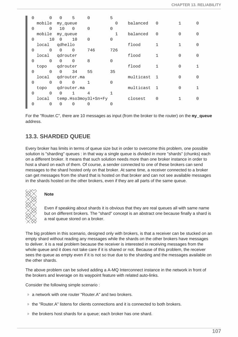
0 0 0 5 0 5 mobile my_queue 0 balanced 0 1 0 0 0 10 0 0 0 mobile my_queue 1 balanced 0 0 0 0 10 0 10 0 0 local qdhello flood 1 1 0 0 0 0 0 746 726 local qdrouter flood 1 0 0 0 0 0 0 8 0 topo qdrouter flood 1 0 1 0 0 0 34 55 35 local qdrouter.ma multicast 1 0 0 0 0 0 0 1 0 topo qdrouter.ma multicast 1 0 1 0 0 0 1 4 1 local temp.Hso3moy3l+Sn+Fy closest 0 1 0 0 0 0 0 0 0
For the "Router.C", there are 10 messages as input (from the broker to the router) on the my_queueaddress.
13.3. SHARDED QUEUE
Every broker has limits in terms of queue size but in order to overcome this problem, one possiblesolution is "sharding" queues : in that way a single queue is divided in more "shards" (chunks) eachon a different broker. It means that such solution needs more than one broker instance in order tohost a shard on each of them. Of course, a sender connected to one of these brokers can sendmessages to the shard hosted only on that broker. At same time, a receiver connected to a brokercan get messages from the shard that is hosted on that broker and can not see available messagesin the shards hosted on the other brokers, even if they are all parts of the same queue.
Note
Even if speaking about shards it is obvious that they are real queues all with same namebut on different brokers. The "shard" concept is an abstract one because finally a shard isa real queue stored on a broker.
The big problem in this scenario, designed only with brokers, is that a receiver can be stucked on anempty shard without reading any messages while the shards on the other brokers have messagesto deliver. it is a real problem because the receiver is interested in receiving messages from thewhole queue and it does not take care if it is shared or not. Because of this problem, the receiversees the queue as empty even if it is not so true due to the sharding and the messages available onthe other shards.
The above problem can be solved adding a A-MQ Interconnect instance in the network in front ofthe brokers and leverage on its waypoint feature with related auto-links.
Consider the following simple scenario :
a network with one router "Router.A" and two brokers.
the "Router.A" listens for clients connections and it is connected to both brokers.
the brokers host shards for a queue; each broker has one shard.
CHAPTER 13. RELIABILITY
107

a sender client connects to the "Router.A" in order to send messages to the queue.
a receiver client connects to the "Router.A" in order to get messages from the queue.
Figure 13.5. Sharded Queue Enabled Topology
With such solution and connecting to the "Router.A", sender and receiver do not know anythingabout sharding; they want send and receive messages to/from the whole queue that is the only thingthey are aware of. They are both connected to the router and see only one address (related to thequeue).
The "Router.A" configuration is something like following.
router { mode: standalone id: Router.A}
listener { host: 0.0.0.0 port: 6000 authenticatePeer: no}
connector { name: BROKER1 addr: 127.0.0.1 port: 5672 role: route-container}
connector { name: BROKER2 addr: 127.0.0.1 port: 5673 role: route-container}
address { prefix: my_queue waypoint: yes
Red Hat JBoss A-MQ 7.0-Beta Using A-MQ Interconnect
108

}
autoLink { addr: my_queue connection: BROKER1 dir: in}
autoLink { addr: my_queue connection: BROKER1 dir: out}
autoLink { addr: my_queue connection: BROKER2 dir: in}
autoLink { addr: my_queue connection: BROKER2 dir: out}
The router has a listener for incoming connection from clients and two connector instances in orderto connect to both brokers. The whole queue is named my_queue hosted in terms of shards onboth brokers and the router is configured with a waypoint for that address. Finally, there are twoauto-links in both directions for that queue on both brokers.
Using the Python sample from the Qpid Proton library, the sender can connect to the "Router.A" andstart to send messages to the queue; the console output is like following.
# python simple_send.py -a localhost:6000/my_queue -m 10all messages confirmed
All messages are confirmed because they reached the queue and, thanks to the default balanceddistribution on the address, the messages are delivered to both shards on the brokers (5 messagesper shard). Using the qdstat tool on the router, the distribution is clear.
# qdstat -b localhost:6000 -lRouter Links type dir conn id id peer class addr phs cap undel unsettled deliveries admin oper ======================================================================================================================= endpoint in 1 6 mobile my_queue 1 250 0 0 0 enabled up endpoint out 1 7 mobile my_queue 0 250 0 0 5 enabled up endpoint in 2 8 mobile my_queue 1 250 0 0 0 enabled up endpoint out 2 9 mobile my_queue 0 250 0 0 5 enabled up
CHAPTER 13. RELIABILITY
109
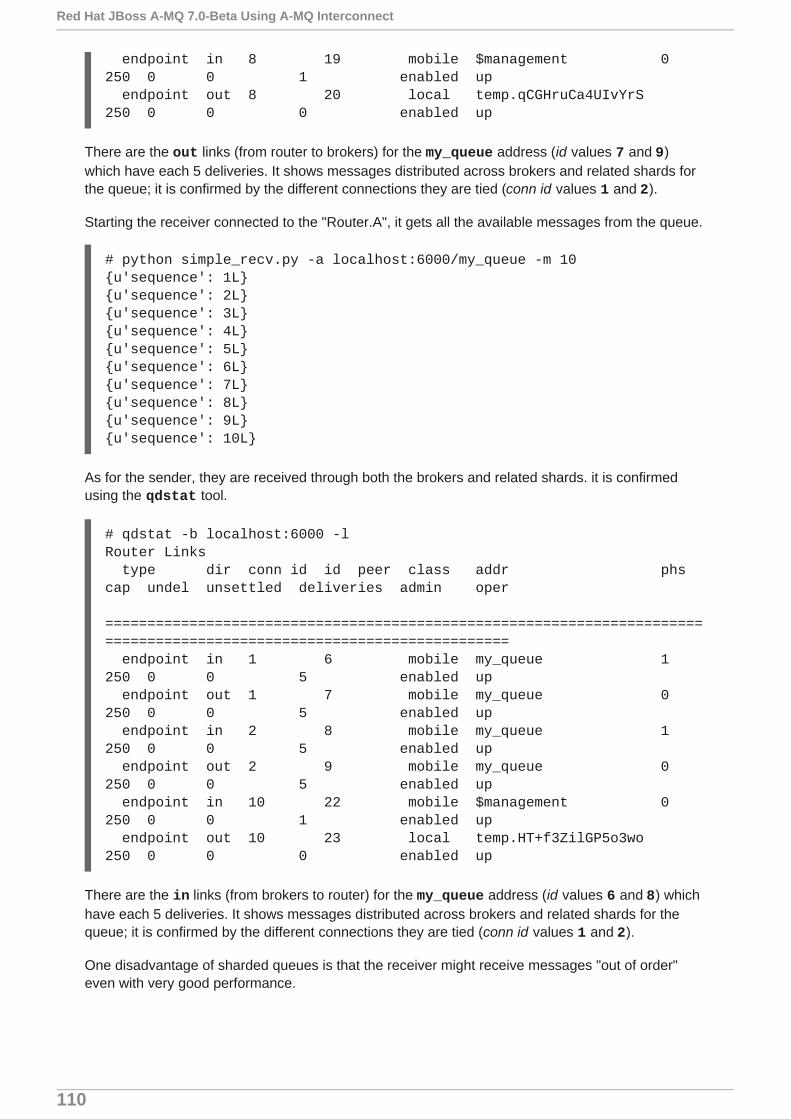
endpoint in 8 19 mobile $management 0 250 0 0 1 enabled up endpoint out 8 20 local temp.qCGHruCa4UIvYrS 250 0 0 0 enabled up
There are the out links (from router to brokers) for the my_queue address (id values 7 and 9)which have each 5 deliveries. It shows messages distributed across brokers and related shards forthe queue; it is confirmed by the different connections they are tied (conn id values 1 and 2).
Starting the receiver connected to the "Router.A", it gets all the available messages from the queue.
# python simple_recv.py -a localhost:6000/my_queue -m 10{u'sequence': 1L}{u'sequence': 2L}{u'sequence': 3L}{u'sequence': 4L}{u'sequence': 5L}{u'sequence': 6L}{u'sequence': 7L}{u'sequence': 8L}{u'sequence': 9L}{u'sequence': 10L}
As for the sender, they are received through both the brokers and related shards. it is confirmedusing the qdstat tool.
# qdstat -b localhost:6000 -lRouter Links type dir conn id id peer class addr phs cap undel unsettled deliveries admin oper ======================================================================================================================= endpoint in 1 6 mobile my_queue 1 250 0 0 5 enabled up endpoint out 1 7 mobile my_queue 0 250 0 0 5 enabled up endpoint in 2 8 mobile my_queue 1 250 0 0 5 enabled up endpoint out 2 9 mobile my_queue 0 250 0 0 5 enabled up endpoint in 10 22 mobile $management 0 250 0 0 1 enabled up endpoint out 10 23 local temp.HT+f3ZilGP5o3wo 250 0 0 0 enabled up
There are the in links (from brokers to router) for the my_queue address (id values 6 and 8) whichhave each 5 deliveries. It shows messages distributed across brokers and related shards for thequeue; it is confirmed by the different connections they are tied (conn id values 1 and 2).
One disadvantage of sharded queues is that the receiver might receive messages "out of order"even with very good performance.
Red Hat JBoss A-MQ 7.0-Beta Using A-MQ Interconnect
110

APPENDIX A. USING CYRUS SASL TO PROVIDEAUTHENTICATION
A-MQ Interconnect uses the Cyrus SASL library for SASL authentication. Therefore, if you want touse SASL, you must set up the Cyrus SASL database and configure it.
A.1. GENERATING A SASL DATABASE
To generate a SASL database to store credentials, enter the following command:
# saslpasswd2 -c -p -f <SASL_database_name>.sasldb -u [<domain_name>] <user_name>
This command creates or updates the specified SASL database, and adds the specified user nameto it. The command also prompts you for the user name’s password.
The full user name is the user name you entered plus the domain name(<user_name>@<domain_name>). Providing a domain name is not required when you add a userto the database, but if you do not provide one, a default domain will be added automatically (thehostname of the machine on which the tool is running). For example, in the command above, the fulluser name would be [email protected].
A.2. VIEWING USERS IN A SASL DATABASE
To view the user names stored in the SASL database:
# sasldblistusers2 -f [email protected]: [email protected]: userPassword
A.3. CONFIGURING A SASL DATABASE
To use the SASL database to provide authentication in A-MQ Interconnect, you must set thefollowing attributes in the Cyrus SASL configuration file:
pwcheck_method: auxpropauxprop_plugin: sasldbsasldb_path: <SASL_database_name>mech_list: <mechanism1 ...>
sasldb_path
The name of the SASL database to use.
For example:
sasldb_path: qdrouterd.sasldb
mech_list
CHAPTER 13. RELIABILITY
111

The SASL mechanisms to enable for authentication. To add multiple mechanisms, separateeach entry with a space.
For example:
mech_list: ANONYMOUS DIGEST-MD5 EXTERNAL PLAIN
Red Hat JBoss A-MQ 7.0-Beta Using A-MQ Interconnect
112

APPENDIX B. CONFIGURATION REFERENCE
The A-MQ Interconnect component behavior is totally configurable using a configuration file whichcan be passed as parameter (with the --conf option) on the command line when running it. Afterinstallation, a default configuration file is placed at the following path :
[install-prefix]/etc/qpid-dispatch/qdrouterd.conf
This file is used when the router is started without specify configuration file path on the commandline and when it is started as a service. In case of starting router on the command line theconfiguration file can be placed anywhere on the file system.
B.1. CONFIGURATION FILE
The configuration file is made up of sections with following syntax :
sectionName { attributeName: attributeValue attributeName: attributeValue ...}
A section could be referenced by another section using its name attribute. An example is thesslProfile section which describes attributes for setting SSL configuration and can be applied to oneor more listener and connector sections.
sslProfile { name: ssl-profile-one certDb: ca-certificate-1.pem certFile: server-certificate-1.pem keyFile: server-private-key.pem}
listener { sslProfile: ssl-profile-one host: 0.0.0.0 port: amqp saslMechanisms: ANONYMOUS}
In the above example, the sslProfile section named ssl-profile-one is used to define the sslProfileattribute for the listener section.
B.1.1. Configuration Sections
B.1.1.1. sslProfile
Attributes for setting SSL configuration for connections.
certDb (path) : The absolute path to the database that contains the public certificates of trustedcertificate authorities (CA).
APPENDIX A. USING CYRUS SASL TO PROVIDE AUTHENTICATION
113

certFile (path) : The absolute path to the file containing the PEM-formatted public certificate tobe used on the local end of any connections using this profile.
keyFile (path) : The absolute path to the file containing the PEM-formatted private key for theabove certificate.
passwordFile (path) : If the above private key is password protected, this is the absolute path toa file containing the password that unlocks the certificate key.
password (string) : An alternative to storing the password in a file referenced by passwordFile isto supply the password right here in the configuration file. This option can be used by supplyingthe password in the ‘password’ option. Don’t use both password and passwordFile in the sameprofile.
uidFormat (string) : A list of x509 client certificate fields that will be used to build a string that willuniquely identify the client certificate owner. For e.g. a value of ‘cou’ indicates that the uid willconsist of c - common name concatenated with o - organization-company name concatenatedwith u - organization unit; or a value of ‘oF’ indicates that the uid will consist of o (organizationname) concatenated with F (the sha256 fingerprint of the entire certificate) . Allowed values canbe any combination of comma separated ‘c’( ISO3166 two character country code), ‘s’(state orprovince), ‘l’(Locality; generally - city), ‘o’(Organization - Company Name), ‘u’(Organization Unit -typically certificate type or brand), ‘n’(CommonName - typically a username for client certificates)and ‘1’(sha1 certificate fingerprint, as displayed in the fingerprints section when looking at acertificate with say a web browser is the hash of the entire certificate) and 2 (sha256 certificatefingerprint) and 5 (sha512 certificate fingerprint).
displayNameFile (string) : The absolute path to the file containing the unique id to display namemapping.
name (string) : The name of the profile used for referencing it from listener and connectorsections.
Used by : listener, connector.
B.1.1.2. router
Describe main information about the router related to identity, internal processes and inter routerscommunication.
id (string) : Router’s unique identity. It is required and the router will fail to start without it.
mode (One of [standalone, interior], default=standalone) : In standalone mode, therouter operates as a single component. It does not participate in the routing protocol andtherefore will not cooperate with other routers. In interior mode, the router operates incooperation with other interior routers in an interconnected network.
helloInterval (integer, default=1) : Interval in seconds between HELLO messages sent toneighbor routers in order to announce its presence (as a keep alive).
helloMaxAge (integer, default=3) : Time in seconds after which a neighbor router is declaredlost if no HELLO is received.
raInterval (integer, default=30) : Interval in seconds between Router-Advertisements sent to allrouters in a stable network.
raIntervalFlux (integer, default=4) : Interval in seconds between Router-Advertisements sent toall routers during topology fluctuations.
Red Hat JBoss A-MQ 7.0-Beta Using A-MQ Interconnect
114

remoteLsMaxAge (integer, default=60) : Time in seconds after which link state is declared staleif no RA is received.
workerThreads (integer, default=4) : The number of threads that will be created to processmessage traffic and other application work (timers, non-amqp file descriptors, etc.) .
debugDump (path) : The absolute path for a file to dump debugging information that can’t belogged normally.
saslConfigPath (path) : The absolute path to the SASL configuration file.
saslConfigName (string, default=qdrouterd) : Name of the SASL configuration. This string +‘.conf’ is the name of the configuration file.
B.1.1.3. listener
Listens for incoming connections to the router.
host (string, default=127.0.0.1) : IP address: ipv4 or ipv6 literal or a hostname.
port (string, default=amqp) : Port number or symbolic service name.
protocolFamily (One of [IPv4, IPv6]) : IPv4: Internet Protocol version 4; IPv6: Internet Protocolversion 6. If not specified, the protocol family will be automatically determined from the address.
role (One of [normal, inter-router, route-container], default=normal) : The role of anestablished connection. In the normal role, the connection is assumed to be used for AMQPclients that are doing normal message delivery over the connection. In the inter-router role, theconnection is assumed to be to another router in the network. Inter-router discovery and routingprotocols can only be used over inter-router connections. The route-container role can be usedfor router-container connections, for example, a router-broker connection.
cost (integer, default=1) : For the inter-route role only. This value assigns a cost metric tothe inter-router connection. The default (and minimum) value is one. Higher values representhigher costs. The cost is used to influence the routing algorithm as it attempts to use the pathwith the lowest total cost from ingress to egress.
saslMechanisms (string) : Space separated list of accepted SASL authentication mechanisms.
authenticatePeer (boolean) : yes: Require the peer’s identity to be authenticated; no: Do notrequire any authentication.
requireEncryption (boolean) : yes: Require the connection to the peer to be encrypted; no:Permit non-encrypted communication with the peer. It is related to SASL mechanisms whichsupport encryption.
requireSsl (boolean) : yes: Require the use of SSL on the connection; no: Allow clients toconnect without SSL.
trustedCerts (path) : This optional setting can be used to reduce the set of available CAs forclient authentication. If used, this setting must provide an absolute path to a PEM file thatcontains the trusted certificates.
maxFrameSize (integer, default=16384) : Defaults to 16384. If specified, it is the maximumframe size in octets that will be used in the connection-open negotiation with a connected peer.The frame size is the largest contiguous set of uninterrupted data that can be sent for a messagedelivery over the connection. Interleaving of messages on different links is done at framegranularity.
APPENDIX B. CONFIGURATION REFERENCE
115

idleTimeoutSeconds : (integer, default=16) : The idle timeout, in seconds, for connectionsthrough this listener. If no frames are received on the connection for this time interval, theconnection shall be closed.
stripAnnotations (One of [in, out, both, no], default=both) : in: Strip the dispatch routerspecific annotations only on ingress; out: Strip the dispatch router specific annotations only onegress; both: Strip the dispatch router specific annotations on both ingress and egress; no - donot strip dispatch router specific annotations.
linkCapacity (integer) : The capacity of links within this connection, in terms of messagedeliveries. The capacity is the number of messages that can be in-flight concurrently for eachlink.
sslProfile (string) : The name of the sslProfile entity to use in order to have SSL configuration.
B.1.1.4. connector
Establishes an outgoing connection from the router.
name (string) : Name using to reference the connector in the configuration file for example for alink routing to queue on a broker.
host (string, default=127.0.0.1) : IP address: ipv4 or ipv6 literal or a hostname.
port (string, default=amqp) : Port number or symbolic service name.
protocolFamily (One of [IPv4, IPv6]) : IPv4: Internet Protocol version 4; IPv6: Internet Protocolversion 6. If not specified, the protocol family will be automatically determined from the address.
role (One of [normal, inter-router, route-container], default=normal) : The role of anestablished connection. In the normal role, the connection is assumed to be used for AMQPclients that are doing normal message delivery over the connection. In the inter-router role, theconnection is assumed to be to another router in the network. Inter-router discovery and routingprotocols can only be used over inter-router connections. route-container role can be used forrouter-container connections, for example, a router-broker connection.
cost (integer, default=1) : For the ‘inter-router’ role only. This value assigns a cost metric to theinter-router connection. The default (and minimum) value is one. Higher values represent highercosts. The cost is used to influence the routing algorithm as it attempts to use the path with thelowest total cost from ingress to egress.
saslMechanisms (string) : Space separated list of accepted SASL authentication mechanisms.
allowRedirect (boolean, default=True) : Allow the peer to redirect this connection to anotheraddress.
maxFrameSize (integer, default=65536) : Maximum frame size in octets that will be used in theconnection-open negotiation with a connected peer. The frame size is the largest contiguous setof uninterrupted data that can be sent for a message delivery over the connection. Interleaving ofmessages on different links is done at frame granularity.
idleTimeoutSeconds (integer, default=16) : The idle timeout, in seconds, for connectionsthrough this connector. If no frames are received on the connection for this time interval, theconnection shall be closed.
Red Hat JBoss A-MQ 7.0-Beta Using A-MQ Interconnect
116

stripAnnotations (One of [in, out, both, no], default=both) : in: Strip the dispatch routerspecific annotations only on ingress; out: Strip the dispatch router specific annotations only onegress; both: Strip the dispatch router specific annotations on both ingress and egress; no - donot strip dispatch router specific annotations.
linkCapacity (integer) : The capacity of links within this connection, in terms of messagedeliveries. The capacity is the number of messages that can be in-flight concurrently for eachlink.
verifyHostName (boolean, default=True) : yes: Ensures that when initiating a connection (as aclient) the hostname in the URL to which this connector connects to matches the hostname in thedigital certificate that the peer sends back as part of the SSL connection; no: Does not performhostname verification
saslUsername (string) : The username that the connector is using to connect to a peer.
saslPassword (string) : The password that the connector is using to connect to a peer.
sslProfile (string) : The name of the sslProfile entity to use in order to have SSL configuration.
B.1.1.5. log
Configure logging for a particular module which is part of the router. You can use the UPDATEoperation to change log settings while the router is running.
module (One of [ROUTER, ROUTER_CORE, ROUTER_HELLO, ROUTER_LS, ROUTER_MA, MESSAGE, SERVER, AGENT, CONTAINER, ERROR, POLICY, DEFAULT], required) : Module toconfigure. The special module DEFAULT specifies defaults for all modules.
enable (string, default=default, required) Levels are: trace, debug, info, notice, warning, error, critical. The enable string is a comma-separated list of levels. A level mayhave a trailing + to enable that level and above. For example trace,debug,warning+ meansenable trace, debug, warning, error and critical. The value ‘none’ means disable logging for themodule. The value default means use the value from the DEFAULT module.
timestamp (boolean) : Include timestamp in log messages.
source (boolean) : Include source file and line number in log messages.
output (string) : Where to send log messages. Can be stderr, syslog or a file name.
B.1.1.6. address
Entity type for address configuration. This is used to configure the treatment of message-routeddeliveries within a particular address-space. The configuration controls distribution and addressphasing.
prefix (string, required) : The address prefix for the configured settings.
distribution (One of [multicast, closest, balanced], default=balanced) : Treatment oftraffic associated with the address.
waypoint (boolean) : Designates this address space as being used for waypoints. This willcause the proper address-phasing to be used.
ingressPhase (integer) : Advanced - Override the ingress phase for this address.
egressPhase (integer) : Advanced - Override the egress phase for this address.
APPENDIX B. CONFIGURATION REFERENCE
117

B.1.1.7. linkRoute
Entity type for link-route configuration. This is used to identify remote containers that shall bedestinations for routed link-attaches. The link-routing configuration applies to an addressing spacedefined by a prefix.
prefix (string, required) : The address prefix for the configured settings.
containerId (string) : it specifies that the link route will be activated if a remote container willprovide a container-id matching with this value.
connection (string) : The name from a connector or listener.
distribution (One of [linkBalanced], default=linkBalanced) : Treatment of trafficassociated with the address.
dir (One of [in, out], required) : The permitted direction of links. It is defined from a router pointof view so ‘in’ means client senders (router ingress) and ‘out’ means client receivers (routeregress).
B.1.1.8. autoLink
Entity type for configuring auto-links. Auto-links are links whose lifecycle is managed by the router.These are typically used to attach to waypoints on remote containers (brokers, etc.).
addr (string, required) : The address of the provisioned object.
dir (One of [in, out], required) : The direction of the link to be created. In means into the router,out means out of the router.
phase (integer) : The address phase for this link. Defaults to 0 for out links and 1 for in links.
containerId (string) : ContainerID for the target container.
connection (string) : The name from a connector or listener.
B.1.1.9. console
Start a websocket/tcp proxy and http file server to serve the web console.
listener (string) : The name of the listener to send the proxied tcp traffic to.
wsport (integer, default=5673) : The port on which to listen for websocket traffic.
proxy (string) : The full path to the proxy program to run.
home (string) : The full path to the html/css/js files for the console.
args (string) : Optional args to pass the proxy program for logging, authentication, etc.
B.1.1.10. policy
Defines global connection limit
maximumConnections (integer) : Global maximum number of concurrent client connectionsallowed. Zero implies no limit. This limit is always enforced even if no other policy settings havebeen defined.
Red Hat JBoss A-MQ 7.0-Beta Using A-MQ Interconnect
118

enableAccessRules (boolean) : Enable user rule set processing and connection denial.
policyFolder (path) : The absolute path to a folder that holds policyRuleset definition .json files.For a small system the rulesets may all be defined in this file. At a larger scale it is better to havethe policy files in their own folder and to have none of the rulesets defined here. All rulesets in all.json files in this folder are processed.
defaultApplication (string) : Application policyRuleset to use for connections with noopen.hostname or a hostname that does not match any existing policy. For users that don’t wishto use open.hostname or any multi-tennancy feature, this default policy can be the only policy ineffect for the network.
defaultApplicationEnabled (boolean) : Enable defaultApplication policy fallback logic.
B.1.1.11. policyRuleset
Per application definition of the locations from which users may connect and the groups to whichusers belong.
maxConnections (integer) : Maximum number of concurrent client connections allowed. Zeroimplies no limit.
maxConnPerUser (integer) : Maximum number of concurrent client connections allowed for anysingle user. Zero implies no limit.
maxConnPerHost (integer) : Maximum number of concurrent client connections allowed for anyremote host. Zero implies no limit.
userGroups (map) : A map where each key is a user group name and the corresponding valueis a CSV string naming the users in that group. Users who are assigned to one or more groupsare deemed ‘restricted’. Restricted users are subject to connection ingress policy and areassigned policy settings based on the assigned user groups. Unrestricted users may be allowedor denied. If unrestricted users are allowed to connect then they are assigned to user groupdefault.
ingressHostGroups (map) : A map where each key is an ingress host group name and thecorresponding value is a CSV string naming the IP addresses or address ranges in that group.IP addresses may be FQDN strings or numeric IPv4 or IPv6 host addresses. A host range is twohost addresses of the same address family separated with a hyphen. The wildcard host address‘*’ represents any host address.
ingressPolicies (map) : A map where each key is a user group name and the correspondingvalue is a CSV string naming the ingress host group names that restrict the ingress host for theuser group. Users who are members of the user group are allowed to connect only from a host inone of the named ingress host groups.
connectionAllowDefault (boolean) : Unrestricted users, those who are not members of adefined user group, are allowed to connect to this application. Unrestricted users are assigned tothe ‘default’ user group and receive ‘default’ settings.
settings (map) : A map where each key is a user group name and the value is a map of thecorresponding settings for that group.
APPENDIX B. CONFIGURATION REFERENCE
119

APPENDIX C. USING YOUR SUBSCRIPTION
Using Your Subscription
Red Hat JBoss A-MQ is provided through a software subscription. To manage your subscriptions,access your account at the Red Hat Customer Portal.
Accessing Your Account
1. Go to https://access.redhat.com/.
2. If you do not already have an account, create one.
3. Log in to your account.
Activating a Subscription
1. Go to https://access.redhat.com/.
2. Navigate to My Subscriptions.
3. Navigate to Activate a subscription and enter your 16-digit activation number.
Downloading Zip and Tar Files
To access zip or tar files, use the customer portal to find the relevant files for download. If you areusing RPM packages, this step is not required.
1. Go to https://access.redhat.com/products/red-hat-jboss-a-mq/.
2. Navigate to Download Latest.
3. Select the Download link for your component.
Registering Your System for Packages
To install RPM packages on Red Hat Enterprise Linux, your system must be registered. If you areusing zip or tar files, this step is not required.
1. Go to https://access.redhat.com/.
2. Navigate to Registration Assistant.
3. Select your OS version and continue to the next page.
4. Use the listed command in your system terminal to complete the registration.
To learn more see How to Register and Subscribe a System to the Red Hat Customer Portal.
Red Hat JBoss A-MQ 7.0-Beta Using A-MQ Interconnect
120