recycling mgo-c refractory in eaf of imexsa
DESCRIPTION
EafTRANSCRIPT
Recycling MgO-C Refractory in the EAF of IMEXSA
R. G. Lule•, A.N.Conejo , F. Lopéz• and R. Rodriguez••
•Process Engineering Department Steelmaking Shop [email protected]
• Head of the refractories department Lázaro Cárdenas City, México. Tel: + (753) 53 32527
Professor. Metallurgy Department. Morelia Technological Institute Morelia, México. Tel + (443) 3125449 ext 298
Key words: Refractory recycling, MgO saturation limits, foaming
ABSTRACT
MgO-C refractory recycling from electric arc furnaces and ladle furnaces has been carried out during the melting of DRI. Metallurgical trials to define the effects of refractory recycling on energy consumption, melting time, flux consumption and refractory consumption are reported in this work. The method of preparation as well as the method of injection is also included in this study. Based on the current results, the practice of recycling spent refractory is highly recommended. Visual inspection indicates the potential benefits in slag foaming since the beginning of the heat which allows the use of full power transformer and in turn leading to faster melting rates.
INTRODUCTION Ispat Mexicana (IMEXSA) produced 4.03 million tons of steel in 2004. The steel shop has four-Electric Arc Furnaces (EAF) with a nominal capacity of 220 tons of liquid steel and two-Ladle Metallurgy Facilities (LMF). Almost 100% of the refractory is made of MgO-C. The current life of the refractory lining for EAF´s is approximately 480 heats with partial patching in hot spots 1 & 2 and breast, and of 165 heats for ladles, with partial patching at 80 heats in the slag line and bottom. Due to new refractory campaigns, the steelshop generates more than 5000 tons/year of spent refractor (1200 and 3800 tons/year from furnaces and ladles, respectively). The previous amount corresponds to approximately 420 ton/month of spent refractory which can be increased up to 500 ton/month if the quality of DRI decreases with a corresponding decrease in refractory life. The purpose of this work is to describe the benefits obtained with the recycling of spent refractory back into the EAF´s, not only economical and environmental but also the resulting improved slag foaming properties and how this in turn can affect the consumption of electrical energy as well as flux and refractory consumption.
BENEFITS OF RECYCLING MGO-C REFRACTORY The practice of recycling spent refractories has been carried out in the past for a long time in many steel plants, this practice, however, has been made, in general, on empirical grounds. Today, with the availability of a large amount of information regarding to the solubility of MgO in slags, slag foaming technology and the acquisition of data through computers, it is possible to contribute with a more detailed analysis. One initial purpose in recycling MgO-C spent refractory is to decrease the amount of fluxes and improve the foaming conditions. MgO saturation limits: MgO refractories are severely attacked by slags non-saturated in MgO. The MgO saturation limit is related to the concentration of other oxide components and the process temperature. The saturation limit is specific for each slag, changes with slag composition and temperature, as follows.
• Decreases as the basicity of the slag increases. • Decreases as the FeO concentration of the slag increases.
• Decreases as the Al2O3 concentration of the slag increases (up to 25% at 1600°C). • Increases as the SiO2 concentration of the slag increases. • Increases as the temperature of the slag increases.
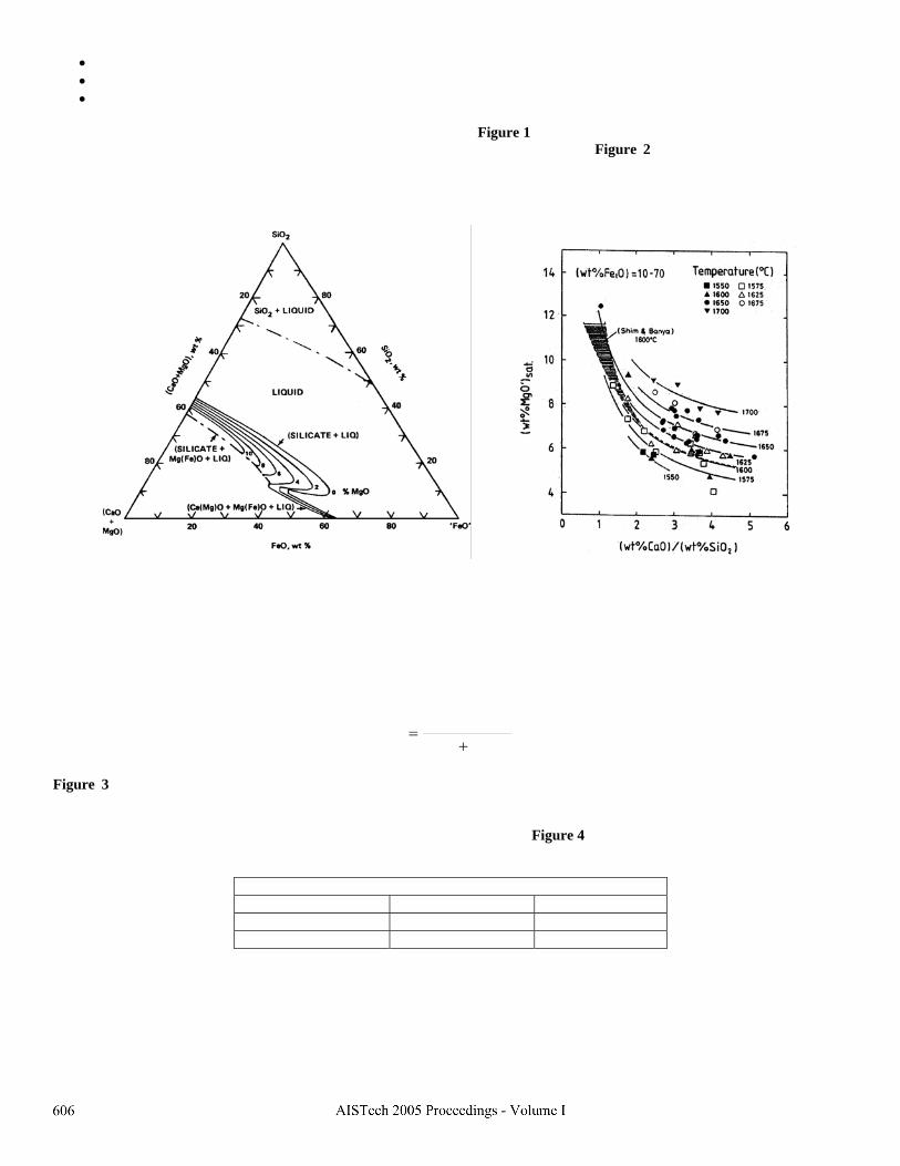
The saturation limits for the CaO-SiO2-FeO-(MgO) system is shown in Figure 1. It is clear from this figure how the saturation limit is decreased when FeO is increased. The effect of basicity and temperature is shown in Figure 2. As the binary basicity ratio is increased, the saturation limit decreases but most importantly, if the basicity is lower than 2, then, a decrease in basicity increases the saturation limit to large values as compared when the basicity is above 2. In order to keep the saturation limit as low as possible a basicity higher than 2 is always recommended.
Figure 1. Saturation limits of MgO in the CaO-SiO -FeO Figure 2. Effect of basicity and temperature 2 system. After Chipman. on MgO saturation limits. After Ban Ya. Pretorius1) developed new maps to represent the saturation limits of MgO for CaO-SiO2-FeO-MgO-Al2O3 slags, as a function of MgO and FeO content at a constant basicity and temperature, called Isothermal Saturation (Solubility) Diagrams (ISD). In this type of diagrams the basicity index is defined as follows.
3223 OAlSiO
CaOB+
=
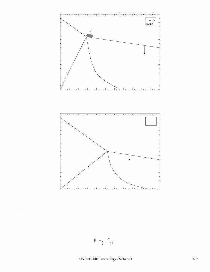
Figure 3 shows the MgO saturation boundaries as a function of iron oxide content for a B3 ratio of 1.5. In this diagram C2S corresponds to calcium di-silicate and MW to magnesio wüstite.The shaded region represents the ideal region recommended to saturate the slag in MgO with the largest possible metallic yield and obtain a small concentration of undissolved particles to increase the viscosity of slags. Below the saturation line the slags present low viscosities. Figure 4 represents the case for a B3 ratio of 2.0. The increase in basicity decreases the MgO saturation limit as indicated by the values reported in Table 1.
Table 1. MgO saturation limit as a function of FeO and basicity B3 = 1.5 B = 2 3
30% FeO 11.6 8.9 40% FeO 12.0 8.3
0 5 10 15 20 25 30 35 40 45 50 55FeO, wt%
0
2
4
6
8
10
12
14
16
18
MgO
, wt%
MW + Liq
MW +C2S+ Liq
C2S+ LiqLiquid
MgO saturation line
B3 = 1.51600°C
Poor foaming ("watery" slags)
ideal region
Figure 3. MgO saturation limits for a B3 ratio of 1.5 and 1600°C
0 5 10 15 20 25 30 35 40 45 50 55FeO, wt%
0
2
4
6
8
10
12
14
16
18
MgO
, wt%
MW + Liq
MW +C2S+ Liq
C2S+ Liq
Liquid
MgO saturation line
B3 = 21600°C
Poor foaming ("watery" slags)
Figure 4. MgO saturation limits for a B3 ratio of 2.0 and 1600°C Slag foaming: Foaming is a fundamental technique to improve heat transfer and get faster rates of melting. A fundamental model applied for industrial conditions has been reported elsewhere2). This kinetic model defines a dynamic foaming index based on slag properties and the generation rate of CO. The final effect of improving foaming results in a decrease in energy consumption. One requisite in slag properties is a good viscosity. By injecting particles of spent refractory into the slag the effective viscosity is increased, according with the following equation.
( ) 5.2e k1 ε−µ
=µ
where: ε represents the fraction of precipitated solid phases and k is a constant, which, according to Roscoe´s formula is equal to 0.35 and according to the modified Einstein´s equation is equal to 1. One reason to select the ideal region in Figure 3 is based on the effect of second phase particles on slag viscosity. It is convenient to operate slightly above the saturation line for MgO. Refractory consumption: Because the injection of MgO-C spent refractory will increase the concentration of MgO and the gradient to reach the saturation limit can be decreases or even eliminated, the corrosiveness of slag towards the refractory can be drastically reduced and a longer life of the refractory can be expected. Practice to increase MgO without increasing the amount of fluxes: There are two ways to increase the concentration of MgO in the slag, one way consists of increasing the amount of dolomitic lime, however, in this way the larger amount of fluxes will increase both costs and electrical energy, the second way is to decrease the concentration of FeO while keeping a good basicity. This task can be accomplished by a proper technique of oxygen injection aiming at low levels of FeO, in the order of 30%.
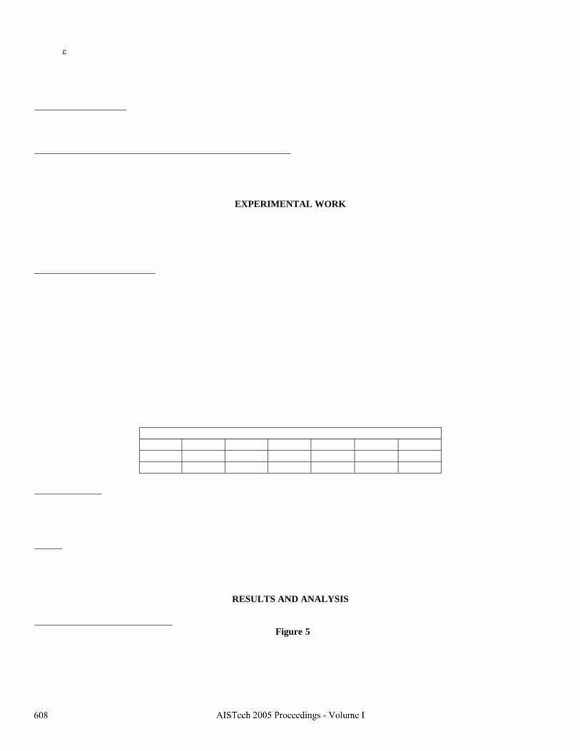
EXPERIMENTAL WORK The steel shop is divided in two modules. One module corresponds to EAF´s # 3 and # 4. Both furnaces are supplied with the same raw materials. EAF # 3 was selected to carry out the evaluation of recycling spent refractory and then compare the results with EAF # 4 which is working under normal conditions. Selection, crushing and packing: Most of the spent refractory is MgO-C with the exception of the bottom of the ladles which is made of Al2O3-C. This refractory must be separated but is not easy to distinguish from MgO-C. Three features assist to separate this material; it has a lower density, grayish color and is covered with a rust due to oxidation. The main reason to separate the alumina is the low basicity of EAF slags and with an addition of this oxide the basicity can be lowered even more. The spent refractory is classified by size, if the size is larger than 8-9 inches is re-used in the free-board of the teeming ladles. The rest is crushed. Crushing is an important operation to achieve an efficient recycling process. The particle size after crushing should be less than 3 mm3). This particle size is recommended in order to complete its melting. There are no significant problems associated with losses by the fume extraction system because charging is conducted in the same stream as for DRI, thus, DRI forces the refractory to penetrate into the slag. After crushing the material, it is packed in jumbo bags of 2 ton. and then transported to the handling materials system. The material is discharged in a bin, through a belt conveyor system. From the bin is discharged continuously into the EAF. Table 1 shows the chemical composition of both new and spent MgO-C refractory. It is reported a MgO content in the order of 75%.
Table 1. Composition of magnesia-carbon refractories %MgO %CaO %SiO2 %Al2O3 %Fe2O3 %C
New 90.7 1.70 0.68 0.78 0.68 18.21 used 74.21 2.83 1.27 1.61 0.45 17.20
Injection flowrate: The spent refractory was discharged continuously together with the addition of DRI, coke and lime at the beginning of the heat with a feeding rate of 150 kg/min. The lowest feeding rate capacity is 100 kg/min. The maximum amount of spent refractory tested in this work was 1 ton per heat. Trials: Three types of trials were carried out, from small scale to large scale to full scale trials. The small scale trials consisted of a preliminary work with 10 heats to define the practice of addition of spent refractory and get a first estimation of the general response. The second set of trials was conducted with 70 heats and the final set of trials consisted of regular additions during three months in one furnace.
RESULTS AND ANALYSIS Current levels of MgO in the slag: The current practice of flux additions considers approximately 35% metallurgical lime and 65% dolomitic lime. The current specific consumption is shown in Figure 5. On average the amount of fluxes added to the furnace is 12 ton/heat, the MgO in the slag contains on average 8.5 ± 1.0%. The binary basicity ratio (B2) is 1.6 to 1.8 and a B3 ratio of 1.3. Based on a mass balance4), the amount of fluxes required to saturate the slag with 14% MgO, assuming a FeO content of 40%, is in the order of 20 tons per heat. This amount is not recommended because of its negative impact on both energy consumption and melting time.

The acid components in the ores employed to produce DRI contains on average 2.7% and 3.1% for the HYL and MIDREX processes, respectively. The larger the amount of acid components will result in lower basicities and then more MgO needed to saturate the slag. Previous to 1992, IMEXSA was working with an erroneous practice5). Metallurgical lime was the only one fluxing agent. This practice provided a maximum concentration of 4% MgO, this concentration is far below the MgO saturation limit and thus an estimated refractory consumption of 6-12 kg/ton was reported. Ever since, a mixture of dolomitic and metallurgical lime has been employed to guarantee, both, basicity and MgO.
4 8 12 16 20 24Fluxes, ton/heat
4
6
8
10
12
14
MgO
, wt%
EAF 1,2,4EAF 3
October 2004
Figure 5. Effect of flux addition practice on MgO in the slag Small scale trials: 10 heats were analyzed, in this set of heats the injection flowrate and amount of spent refractory was defined. Slag sampling was carried out at 70, 160 and 220 ton. The average composition of fluxes and DRI supplied is shown in Tables 2 and 3. An average of 31% MgO was reported for dolomitic lime, this is, roughly, 50% less than the content in the spent MgO-C refractory. A comparison in consumption factors between EAF # 3 and the rest of the furnaces is given in Table 4.
Table 2. Chemical composition of fluxes employed during the small scale trials %MgO %CaO %SiO2 %R2O3 %LOI
Metallurgical lime 3.30 86.1 1.68 1.27 7.65 Dolomitic lime 31.16 54.39 1.02 1.11 12.32
Table 3. Average chemical composition of DRI employed during the small scale trials
% Fet % Fe° % Met %C %S Midrex 90.3 82.0 90.8 1.97 0.0013 HyLIII 90.4 83.5 92.3 2.16 0.0030
Table 4. Comparison of consumption factors
Concept Unit Average EAF # 3
Average EAF # 1,2,4
DRI Ton 221.2 226.1 Scrap Ton 50.3 17.4
O2 Nm3 4621 4246 Dolomitic Lime ton 6.870 7.800
Metallurgical Lime ton 4.700 3.800 Total fluxes ton 11.570 11.600
Coke Kg 530 600 Graphite Kg 263 421.8
Refractory MgO-C Kg 1000 0 Energy kwh/ton 592.3 613.2
Power On minutes 56.9 59.4 ton/Heat Ton 207.5 204.7
The previous table indicates a lower consumption of electrical energy in EAF # 3 as compared to the other furnaces, in the order of 20 kwh/ton and faster melting times. The heat weight is taken based on the turret´s weight from continuous casting. It was also observed that the spent MgO-C refractory increased the viscosity of the slag, promoting a “creamy” slag instead of a “watery” slag in the major part of the melting step. The spent refractory is added in the first 7 minutes of the heat. The slag generated, with a higher viscosity, is more adequate to promote slag foaming. In order to take full advantage of the potential of this type of slag the breast of the slag door was increased, thus, retaining the slag inside of the furnace for a longer period of time. The early injection would result in a progressive decrease in MgO throughout the heat. Table 5 shows some results of the change in MgO throughout the heat. It can be observed a decrease of MgO content in some heats but in others the MgO content remains almost constant, which is an indication that the early addition is convenient to complete the melting of the refractory particles and also to keep a high level of MgO throughout the heat. An additional advantage of the early addition is the dilution effect over the highly oxidized slag that remains from the previous heat, which in the conventional case it would take longer time to get conditions for foaming. With the addition of refractory particles foaming is achieved immediately at the beginning of the heat. The arc distortion value is lower than 8. This in turn allows operating almost immediately to full transformer capacity (133 MW) and remain so throughout the heat, which results in faster melting times.
Table 5. Sampling results of %MgO through the heat at 100 ton 150 ton 200 ton
A 9.08 9.37 9.38 B - 10.33 8.8 C 8.47 8.81 8.61 D 10.38 9.03 8.03 E 9.79 9.38 8.43 F 10.40 10.14 -
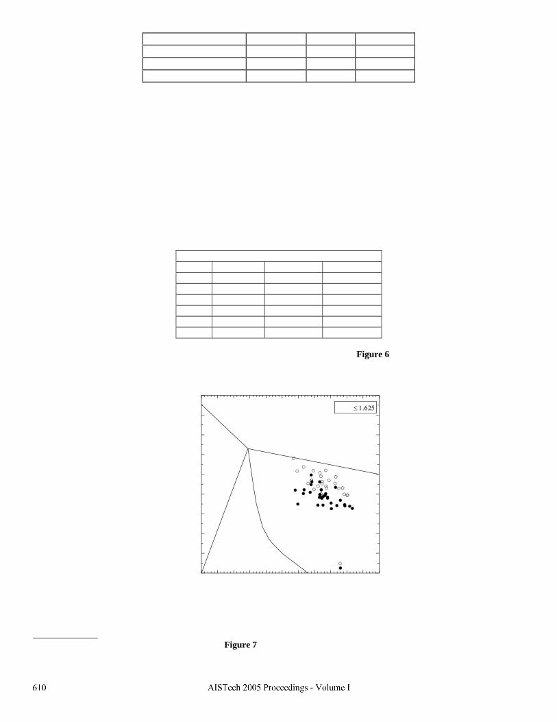
The average ternary basicity (B3) was 1.13. The isothermal saturation diagram shown in Figure 6 displays results for ternary basicities from 0-1.625, this figure compares the MgO content, reported at 100 ton, between EAF # 3 and the others. It can be seen a larger content of MgO for the heats of EAF # 3, closer to the MgO saturation values. On average the MgO content is 1.5% higher in EAF #3.
0 5 10 15 20 25 30 35 40 45 50 55FeO, wt%
0
2
4
6
8
10
12
14
16
18
MgO
, wt%
MW + Liq
MW +C2S+ Liq
C2S+ LiqLiquid
MgO saturation line
0 <B3 ≤ 1.625
recycling MgOstd practice
Figure 6. Isothermal stability diagram showing MgO levels for the small scale trials Large scale trials: 70 heats in EAF # 3 were compared with heats processed en EAF # 4. Slag samples were taken at 100 tons. Table 6 compares the average results from EAF´s # 3 and 4. Figure 7 compares the composition of slags in both cases.

Table 6. Results from second trials (70 heats)
EAF # 3 EAF # 4 Difference CaO 23.4 % 22.9 SiO2 15.4 % 15.2 MgO 9.5% 7.6 + 2.1 FeO 36.5 % 38.5
Al2O3 5.3 % 4.7 Energy, kwh/ton 586.9 613.6 – 26.7
Dolomitic lime (ton(heat) 7 7.7 Metallurgical lime (ton/heat) 4.2 4.8
Total fluxes (ton/heat) 11.2 12.5 – 1.3 Melting time 59 61.9 – 2.9
0 5 10 15 20 25 30 35 40 45 50 55FeO, wt%
0
2
4
6
8
10
12
14
16
18
MgO
, wt%
MW + Liq
MW +C2S+ Liq
C2S+ LiqLiquid
MgO saturation line
0.85 <B3 ≤ 1.53
recycling MgOstd practice
Figure 7. Isothermal stability diagram showing MgO levels for the second set of trials From the previous results it can be observed benefits in lower energy consumption, a larger concentration of MgO and lower flux consumption in the furnace using recycled refractory. The slag s from EAF # 3 are closer to the saturation limit. Full scale trials The practice of recycling spent refractory has been implemented as a routine practice in EAF #3 since October 2004. Table 7 compares the average results from EAF´s # 3 and # 4 during October 2004.
Table 7. Results from full scale trials (October 2004) EAF # 3 EAF # 4 Difference
MgO 9.1% 8.3 + 0.8 Energy, kwh/ton 578.9 594.6 –15.7
Total fluxes (ton/heat) 11.3 12.60 – 1.3 Melting time (min/heat) 60 63 - 3

0
5
10
15
20
25
30
35
40
FeO CaO SiO2 MgO Al2O3 V2
38.4%
26.6%
15.4%
9.1%
5.7%
1.74
EAF # 3Oct 2004
0
5
10
15
20
25
30
35
40
FeO CaO SiO2 MgO Al2O3 V2
37.7%
28.8%
15.0%
8.3%
5.4%
1.97
EAF # 4Oct 2004
Figure 8. Comparison of the average chemical composition of slags from EAF # 3 and # 4
0 5 10 15 20 25 30 35 40 45 50 55FeO, wt%
0
2
4
6
8
10
12
14
16
18
MgO
, wt%
MW + Liq
MW +C2S+ Liq
C2S+ LiqLiquid
MgO saturation line
0.95 <B3 ≤ 1.73
recycling MgO (EAF 3)
0 5 10 15 20 25 30 35 40 45 50 55
FeO, wt%
0
2
4
6
8
10
12
14
16
18M
gO, w
t%
MW + Liq
MW +C2S+ Liq
C2S+ LiqLiquid
MgO saturation line
0.95 <B3 ≤ 1.73
std practice (EAF 1,2,4)
Figure 9. Isothermal stability diagram showing Figure 10. Isothermal stability diagram showing MgO levels, employing spent refractory MgO levels in the conventional practice
1 1.5 2 2.5 3B3 (CaO/SiO2+Al2O3)
5
6
7
8
9
10
11
12
13
14
15
16
(MgO
), w
t%(MgOsat, wt% at 1600°C)
Figure 11. Relationship between slag basicity (B3) and MgO in the slag
The most important feature in this figure is the large increase in MgO solubility for slags with basicity levels less than 2. Due to the large availability of data, several correlations were made between slag basicity and energy consumption at different ranges of FeO. Aminorroaya6) reported an optimum basicity range in terms of energy consumption, however the correlation coefficient for several correlations was 0, therefore, this relationship couldn’t be validated in the present work.
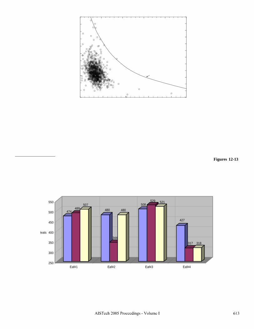
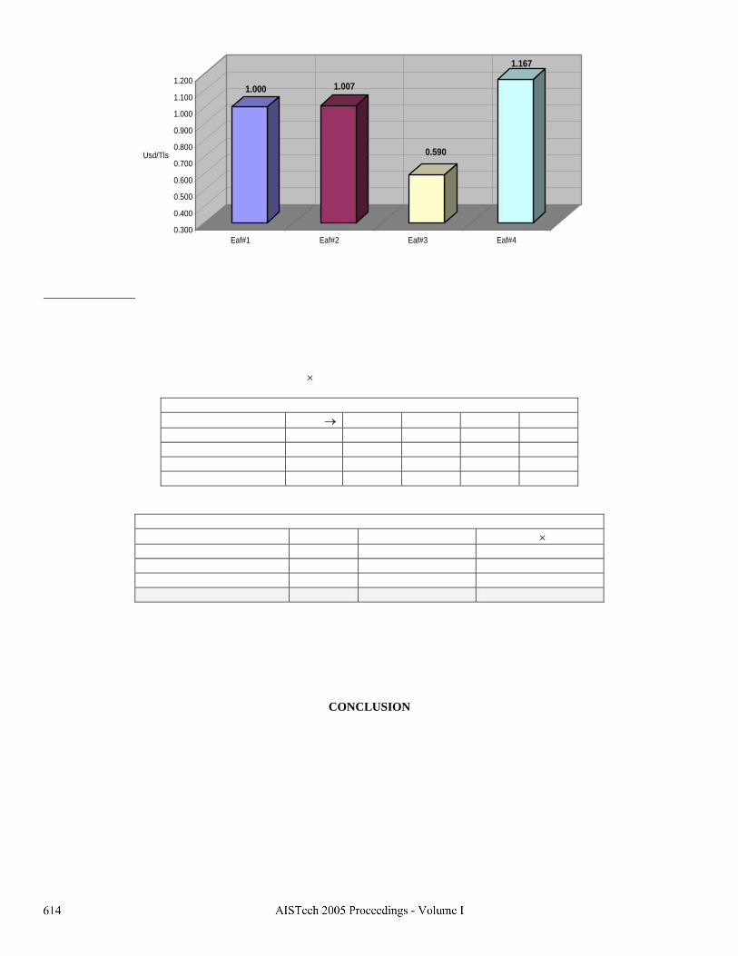
Refractory consumption The last three campaigns in the period from November to December were compared. The results are presented in Figures 12-13. Figure 12 shows the number of heats in the last three campaigns by furnace. It is clearly seen a greater refractory life for EAF # 3, this in turn is reported in terms of refractory costs by campaign in Figure 13. The lowest refractory cost is for EAF # 3. Surprisingly, the longer life in furnace # 3 is achieved even though it supplies steel to the RH unit, which requires a large overheating and tapping temperatures in the order of 1700-1750°C. The shorter life reported in EAF # 4 was due to the process of implementation of a new system for oxygen injection (jet box) and adjustments in process variables such as the injection angle.
474489
507480
344
480
508529 521
427
317 318
250
300
350
400
450
500
550
Heats
Eaf#1 Eaf#2 Eaf#3 Eaf#4
Figure 12. Refractory life per furnace
1.000 1.007
0.590
1.167
0.300
0.400
0.500
0.600
0.700
0.800
0.900
1.000
1.100
1.200
Usd/Tls
Eaf#1 Eaf#2 Eaf#3 Eaf#4
Figure 13. Average refractory cost in three campaigns
Economic analysis: A comparison of average performance between EAF # 3 and EAF # 4 is shown in Table 8 for three months of continuous operation with the new practice EAF #3. The data included in the table corresponds to the difference in results in EAF # 3 with respect to EAF # 4. The average results are expressed as savings, considering the unit costs reported in Table 9. The savings originated from refractory consumption were taken directly from the information provided in Figure 13. Net savings consider the cost of crushing the refractory, this cost is 26 USD/ton refractory or 0.12 USD/ton steel, considering a heat size of 210 tons and an addition of 1 ton refractory/heat. The final result yields an estimated amount of savings of 1.25 USD/ton. Considering an average of 400 heats/month, the final saving are 105,000 USD/month × furnace.
Table 8. Furnace comparison with and without recycling refractory Month→ 1 2 3 avg
MgO Saturation limit MgO + 0.80 + 0.83 +0.59 + 0.74 Energy consumption kwh/ton – 15.7 – 11.19 – 11.01 – 12.62
Flux consumption ton/heat – 1.3 – 1.45 – 1.02 – 1.25 Melting time (p-on) min/heat – 3 – 2.51 – 2.97 – 2.82
Table 9. Savings resulting with the use of recycling spent refractory Unit cost USD/ton × furnace
Electrical energy 12.62 0.042078 USD/kwh 0.53 Fluxes 1.25 64.5 USD/ton 0.38
Refractory savings – 0.465 USD/ton 0.465 Total 1.25
Recycling more than 1 ton per heat is possible but the savings in energy consumption could revert due to more energy required to melt the excess refractory, unless the quality of the metallic charge lets an increase in the volume of oxygen injected, thus, supplying additional chemical energy to melt the spent refractory. There are even cases where the quality of DRI does not allow to melt 1 ton/heat but in general this is not the case.
CONCLUSION Refractory recycling has a positive impact on several processing variables in steelmaking. According with this investigation, recycling 1 ton/heat at the beginning of the process leads to improve the slag foaming properties, resulting in a decrease in the consumption of electrical energy, longer refractory life due to reach a MgO concentration closer to the saturation limit, additionally, it also decreases both the consumption of fluxes and melting time. The economic benefit of recycling 1 ton/heat was estimated to be about 1.26 million USD/year per furnace.

ACKNOWLEDGEMENTS
The authors acknowledge the support of the company to carry out this work as well as permission to publish it, in particular to Mr. Vijay Bhatnagar, CEO, and Mr. Raul Torres, Director of steelmaking and continuous casting.
REFERENCES 1. E.Pretorious. R.C.Carlisle; “Foamy Slag Fundamentals and their Practical Application to the EAF Steelmaking” 1998 EAF
Conference, ISS, pages 275-291. 2. A. N. Conejo, R. Morales and H. Rodríguez, “Mathematical modeling of the EAF process using direct reduced iron”, 59th
Electric Arc Furnace Conference, ISS, November 2001, Phoenix, AZ, USA, pp. 797-810 3. J.P.Bennet, H.S.Kwong,.R.Krabbe, C.Karr and .E.Wilson; “Spent Refractory as Slag Conditioning Additive in the EAF”, 2000
EAF Conference, pages 379-390. 4. M. Lowry, Mittal Steel-East Chicago, Internal report, 2004. 5. A. Conejo and S. Aguilar; “Engineering of EAF slags”, 1992 EAF proceedings, Atlanta, USA, p. 207. 6. S. Aminorroaya and H. Edris; “The effect of foamy slag in the electric arc furnaces on energy consumption”, European Electric
conference, Venice Italy, 2003