record_2.docx
DESCRIPTION
goodTRANSCRIPT

1. INTRODUCTION
Broadcasting is the distribution of audio and video content to a dispersed audience via any audio or visual mass communications medium, but usually one using electromagnetic radiation (radio waves). The receiving parties may include the general public or a relatively large subset thereof. Broadcasting has been used for purposes of private recreation, non-commercial exchange of messages, experimentation, self-training, and emergency.Types of Broadcasting:
Telephone broadcasting (1881–1932): the earliest form of electronic broadcasting (not counting data services offered by stock telegraph companies from 1867, if ticker-tapes are excluded from the definition). Telephone broadcasting began with the advent of Théâtrophone ("Theatre Phone") systems, which were telephone-based distribution systems allowing subscribers to listen to live opera and theatre performances over telephone lines, created by French inventor Clément Ader in 1881. Telephone broadcasting also grew to include telephone newspaper services for news and entertainment programming which were introduced in the 1890s, primarily located in large European cities. These telephone-based subscription services were the first examples of electrical/electronic broadcasting and offered a wide variety of programming.
Radio broadcasting (experimentally from 1906, commercially from 1920): radio broadcasting is an audio (sound) broadcasting service, broadcast through the air as radio waves from a transmitter to a radio antenna and, thus, to a receiver. Stations can be linked in radio networks to broadcast common radio programs, either in broadcast syndication, simulcast or sub-channels.
History of television broadcasting (telecast), experimentally from 1925, commercial television from the 1930s: this television programming medium was long-awaited by the general public and rapidly rose to compete with its older radio-broadcasting sibling.
Cable radio (also called "cable FM", from 1928) and cable television (from 1932): both via coaxial cable, serving principally as transmission mediums for programming produced at either radio
1

or television stations, with limited production of cable-dedicated programming.
Direct-broadcast satellite (DBS) (from circa 1974) and satellite radio (from circa 1990): meant for direct-to-home broadcast programming (as opposed to studio network uplinks and downlinks), provides a mix of traditional radio or television broadcast programming, or both, with dedicated satellite radio programming. (See also: Satellite television)
Webcasting of video/television (from circa 1993) and audio/radio (from circa 1994) streams: offers a mix of traditional radio and television station broadcast programming with dedicated internet radio–webcast programming.
This report gives the details of all the processes involve in broadcasting of audio and video signals through different medium.
2

2. ABOUT DOORDARSHAN KENDRA JALANDHAR
Doordarshan Kendra Jalandhar also referred as Jalandhar Doordarshan is an Indian television station in Jalandhar, owned and operated by state-owned Doordarshan, the television network of Prasar Bharati (Broadcasting Corporation of India). It was established in 1979, and now produces and broadcasts the 24-hour Punjabi language TV channel, DD Punjabi, which was launched in 1998 and covers most of the state of Punjab, India.The whole production chain is divided into different sections as follows:
Studio XTR(External Station) OB(Outdoor Broadcasting) Van ENG(External News Gathering) Computer section(CS) Earth Station(ES)
Detail about the above sections will be given in the following chapter.
History:Doordarshan Kendra Jalandhar was inaugurated on 13 April 1979, after it was shifted here from Amritsar, where it was first established on 23rd
September 1973. It's established here instead of Amritsar was made possible by the efforts of then union I&B minister, I. K. Gujral. The station is located at Gujral Nagar, the center has elaborate programmes production facilities and large studios.
The transmission was initially limited to few hours in a day. Besides the regional language Punjabi, some programs in Hindi and Urdu were also telecast. Even programs in Haryanvi and Himachali languages were telecast from this Kendra as these states did not at that time have their own Kendras.
With the introduction of regional language satellite services, all regional centers of Doordarshan started generating programmes in their respective regional languages. Thus, DD Punjabi came into existence along with many other channels of Doordarshan. A satellite earth station built at the cost of 82.5 million (USD$1.4 million), was inaugurated at the station on 7 august 1998, to allow Punjabi language programs broadcasted from the station, available to neighboring countries like Pakistan, Afghanistan, Oman, Qatar and Nepal.
3

DD Punjabi:Presently, Doordarshan Kendra, Jalandhar telecasts its programmes under the brand name DD Punjabi. DD Punjabi Channel was launched in 1998, and it became a 24-hour service within two years. In its terrestrial mode DD Punjabi has near 100 per cent reach in the State of Punjab. Besides that, numerous Punjabi viewers residing in different parts of India watch the cultural programmes broadcast on DD Punjabi with interest.
Programmes:
Doordarshan Kendra Jalandhar produces a wide spectrum of programmes including serials, documentaries, musical programmes, reality shows, news and current affairs programmes and utility programmes related to health, agriculture and civic issues, etc.
Doordarshan Kendra Jalandhar has, over the years, produced a number of programmes which not only have been popular among viewers, but have left long lasting impressions.
TV Shows:
Serialised TV shows like Sandali Paidan, Kach Dian Mundaran, Mela Melian Da and Lashkara, the Quiz programmes: Bees Sawal, Parakh etc., have entertained and educated the viewers over the years, they have also created awareness about richness of Punjabi culture and traditions.
New Year Eve Special Programmes:
Special TV Shows produced by Jalandhar Doordarshan have been extremely popular among viewers due to high quality production and star value.
Awards and Nominations:
Programs produced by Jalandhar Kendra have won a number of awards over the years. Jalandhar Kendra won the best Doordarshan Kendra of the year Trophy at the Second Doordarshan Awards held in 2002.
4

3 DIFFERENT SECTIONS AND THEIR WORKING:3.1 Introduction:DDK Jalandhar is divided into mainly 6 sections as follows:
Studio XTR(External Station) OB(Outdoor Broadcasting) Van ENG(External News Gathering) Computer section(CS) Earth Station(ES)
All these sections work together 24*7 for efficient production and broadcasting. The working, role and equipments used in all the sections are explained in detail in this chapter.
3.2 STUDIO:This section comprises of three studio A, B, C and is aided by PCR’S(Program Control Room), CCU(Camera Control Room)and CAR(Common Apparatus Room).Studio is used for indoor production like news, talk shows, etc. It is used for all indoor production and an integral part of the whole production chain.
3.2.1 Studio A, B and C:Studio A, B and C comprises of the material and space required for recording a program for broadcasting. Every studio is equipped with two to three cameras for recording which are connected to PCR or CCU for editing and further processing for production. Below is a basic chain of studio.
Fig 3.1 studio chain
5
CAR
PCREDITING &GRAPHICS
VTRRECORDING
&PLAYBACK

3.2.2 PCR :
Program control room is us to control all the programs which are recorded in the studio. It consists of vision mixer, audio mixer, camera control, character generator, graphics etc. PCR is the core of production control as all the video and audio signals are controlled in PCR.
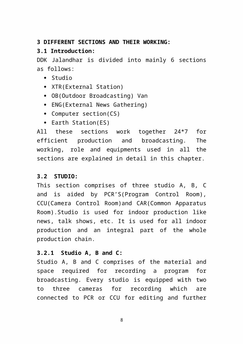
3.3.3 CAR:
CAR is the nerve centre for the TV station, the main activities in this area include
Distribution of stabilized power supply to different technical area with protection:
Sync pulse generation and distribution Video processing and routing Monitoring facilities Patch panel for Audio/Video Electronics for switchers and cameras Electronics for OFC Link Electronics for STL/ Micro wave Link Receiving of External/ OB Signal and its distribution
Equipments in CAR:
Sync Pulse Generator Master Clock Command System Stabilizing Amplifier. 16 X 16 A/V Router Audio/ Video distribution Electronics for video switcher for all studios. Peripherals e.g. (ADC,DAC,SEA,VEA ,MUX,DEMUX etc)
installed in various places in video chain as per requirement.
6

Fig 3.2 Inside CAR
3.3 OUTDOOR BROADCASTING (OB) VAN:
Outdoor broadcasting (OB) is the electronic field production (EFP) of television or radio programmes (typically to cover television news and sports television events) from a mobile remote broadcast television studio. Professional video camera and microphone signals come into the
7
production truck for processing, recording and possibly transmission. The mobile production control room (PCR) is known as a "production truck", "mobile unit", "remote truck", "live truck", "OB van" or "live eye".
Fig 3.3 DDK Jalandhar OB Van
A typical OB van is usually divided into five parts.
Parts of the television crew are located in the first and largest part is the video production area. The television director, technical director, assistant director, character generator (CG) operator and television producers usually sit in front of a wall of video monitors. The technical director sits in front of the video switcher. The video monitors show all the video feeds from various sources, including computer graphics, professional video cameras, video tape recorder (VTR), video servers and slow-motion replay machines. The wall of monitors also contains a preview monitor showing what could be the next source on air (does not have to be depending on how the video switcher is set up) and a program monitor that shows the feed currently going to air or being recorded. The keyed dirty feed (with digital on-screen graphic) is
8

what is actually transmitted back to the central studio that is controlling the outside broadcast. A clean feed (without the graphics) could be sent to other trucks for use in their production. The video switcher is usually operated by one person called the technical director (TD) and is responsible for switching the video sources to air as directed. Behind the directors there is usually a desk with monitors for the editors to operate. It is essential that the directors and editors are in communication with each other during events, so that replays and slow-motion shots can be selected and aired. The "production room" in most sporting events has a graphics operator and sometimes a font coordinator who are in charge of the graphics, statistics, and the showing of the names of commentators or the players to be shown on air. Most sports also have a "box operator" (or "bug box operator") who controls the graphic seen either on the bottom or top of the screen that shows the score as seen at home. These operators can also show on-air stats, control the clock, and many times are also in charge of showing sponsors during play.
The second part of a van is where the audio engineer has an audio mixer (being fed with all the various audio feeds: reporters, commentary, on-field microphones, etc.). The audio engineer can control which channels are added to the output and follows instructions from the director. They relay the information from producers and directors to their A2's who typically set up the audio cables and equipment throughout the arenas and the booth where the commentators sit. The audio engineer normally also has a dirty feed monitor to help with the synchronization of sound and video.
The third part of the truck is the VTR area. The tape area has a collection of machines including video servers and may also house additional power supplies or computer equipment. The "tape room" has EVS (or LSM) operators who have one or more cameras that go into their machines and can be played back for replays when an exciting or important play occurs during the game. EVS operators also play replay rollouts that lead into commercial breaks or show the highlights of the event at the end of play. These operators also can play back in slow motion or pause to show a key part of the action.
9

The fourth part is the video control area where the professional video cameras are controlled using camera control units (CCU) by one or two operators, to make sure that the iris is at the correct exposure and that all the cameras look the same. These operators can shade, balance, and focus the cameras from this position inside the truck. This area is controlled by an operator called a V1 and depending on the size of the show and/or the broadcast company may have a V2.
The fifth part is transmission where the signal is monitored by and engineered for quality control purposes and is transmitted or sent to other trucks. The transmission is monitored by the truck engineers to ensure the people at home have a good picture and a high quality signal output.
The OB Van in Jalandhar DDK has the following features:
CCU VTR(Video Tape Recorder) Character Generator (CG) Graphics Embedder Video Distributing Amplifier Tally Tri-axel cables for data transfer 8 cameras Live Slow Motion (LSM) Audio Console
Video chain of OB VAN:
Output from the switcher goes to stabilizing amplifier via PP and VDAs.
Output from the stab. Is further distributed to various destinations. It may be noted that the use of VDAs helps to monitor the video signal at different locations and the use of PP is very helpful for emergency arrangements during breakdowns and trouble shooting.
A separate monitoring bus is provided in CCU, LCU and END CONTROL with sources as.
10
END CONTROL also has a remote for the adjustment of levels etc. in the STAB AMP unit. R
out for the other sources is similar to this and can be understood from the block schematic.
Fig 3.3 Video Chain
OB Van is used for live broadcasting of significant events, sport events and national events in the state. The OB Van of DDK Jalandhar is used for every major event in the whole of Punjab and for certain events in North India.
11

Fig 3.4 Inside OB Van
When there is the requirement of live transmission of the program captured by OB Van the DSNG Van com into significance
DSNG VAN:
This is known as direct satellite news gathering. It works simultaneously with OB van. It’s also called as mobile earth station. The dish can be aligned acc to the requirement. Monitors are available in this van to check the telecast. High power ups are also available in this van.
DSNG Van of DDK Jalandhar features and usage:
BEL made Vehicle mounted c-Band DSNG is working since September 2002.
A large number of coverage’s of national and international importance has been covered by this van.
Equipment is installed in 1+1 configuration.
12

One of Encoder cum Modulator E5740 is defective and unserviceable
However system is being used in 1+1 configuration temporarily by taking Encoder and Modulator on loan from PGF Jammu .
This unit E 5740 is urgently required to maintain reliability of system.
Fig 3.5 DSNG Van
Parameters For DSNG Service:
Satellite Insat 4B , 93.5 degree East Uplink Freq. 5971 MHz ,Pol. V Down link freq. 3756 MHz, Pol. H Symbol Rate 3.8 Msps FEC 3/4
3.4 ELECRONIC NEWS GATHERING (ENG):
13

Electronics news gathering or electronics field production abbreviated as ENG/EFP is the very important section in Doordarshan network.All outdoor news including VIP/VVIP & international events and programme including Plays, Documents, Song Picturisations have been carried by this section. ENG crew with the help of ENG equipments carries out all type of ENG coverage.
ENG crew details Producer/Director Cameraman Recording Engineer Lighting Assistant Motor Driver.
Equipments used IN ENG section for coverage : Portable camcorder Microphone with Audio cable Head phone for monitoring Audio signal Video tapes for recording. Camera Tripod with spreader. 12V NiCd rechargeable battery with battery charger or AC adopter. Lights:-Mini light for news coverage & halogen type light for
programmes including reflectors Fold back facility for song picturisation such as CD player. Video monitor for monitoring the video signal.
Equipments used in dubbing & in linear editing Editing VCR (DVCPRO & BETACAM FORMAT) Edit controller. Video effects generator such as Magic Dave etc. Audio mixer. Video monitors. Ampli speaker. CD player Microphone for audio dubbing.
14

Fig 3.6 Simple ENG Camera
CAMERA/CAMCORDER Video camera consists of the following sections: -
Camera Optics Camera electronics Recorder
Camera Optics Lens Optical block Transducer or pick up device. Electronics
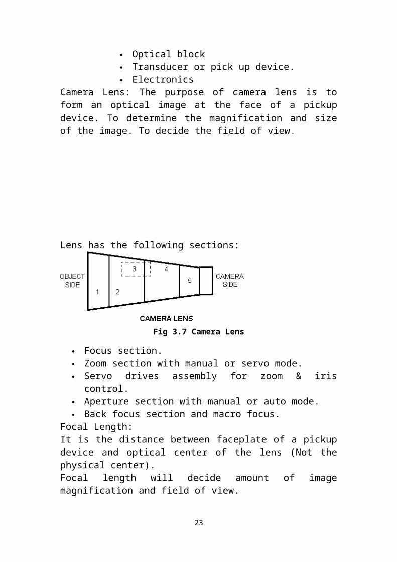
Camera Lens: The purpose of camera lens is to form an optical image at the face of a pickup device. To determine the magnification and size of the image. To decide the field of view.
15

Lens has the following sections:
Fig 3.7 Camera Lens
Focus section. Zoom section with manual or servo mode. Servo drives assembly for zoom & iris control. Aperture section with manual or auto mode. Back focus section and macro focus.
Focal Length:It is the distance between faceplate of a pickup device and optical center of the lens (Not the physical center).Focal length will decide amount of image magnification and field of view.Focal length varies between 9mm to 108mm of a typical camera lens.Zoom Lens:A lens with a variable focal length is called zoom lens.If focal length varies between 9mm to 108mm,The zoom ratio becomes 108/9=12:1Focal length can be varied either manually or servo motor to get different composition of picture
Lens cleaning:Lenses and optical blocks are expensive items of equipment and one of their worst enemies is dust. Care must be taken to ensure that they are kept free from dust by capping the lens when not in use. Lens or optical block surfaces should never be touched by hand or cleaned with handkerchief.
Optical BlockOptical assembly is located inside the camera head and has:
Color filters wheel. Prism & Dichroic Mirrors. Bias light and a suitable lens mount.
16

Color filter wheel include the following filters Opaque filter as a cap. Clear filter for indoors lighting of 3200o K. Reddish filter to match outdoor (4800o K) with indoor. Extra Reddish filter to match outdoor (6500o K) with indoor and
this is sometimes accompanied by NDF to cut the light.
These filters may vary slightly from camera to camera.Fine adjustment for color temperature is done by means of white balance operations.
ND FiltersWhen the scene is too bright for the aperture, a ND filter (Neutral Density) is used to cut down the overall intensity. These transparent dics are usually fitted in a filter wheel behind the camera lens.
Color Temperature: It is the temperature of a black body radiator at which the color of a light source and black body radiator are identical. Color temperature is measured in Kelvin. Higher the color temperature, light will become blueish and lower the color temperature light will tend to be reddish.
White Balance: - The camera is balanced. When input light is reflected (89.9%) from a white test chart and equals primary units of R, G, and B are produces. AWB is achieved by adjusting gain factor of R & b channels so that R & B channels equals to green channel automatically.
Black Balance: -Each pick up device gives some signal even when lens is capped. To correct reproduction of tones and colors, it is necessary that the black level should be same for all the three devices.
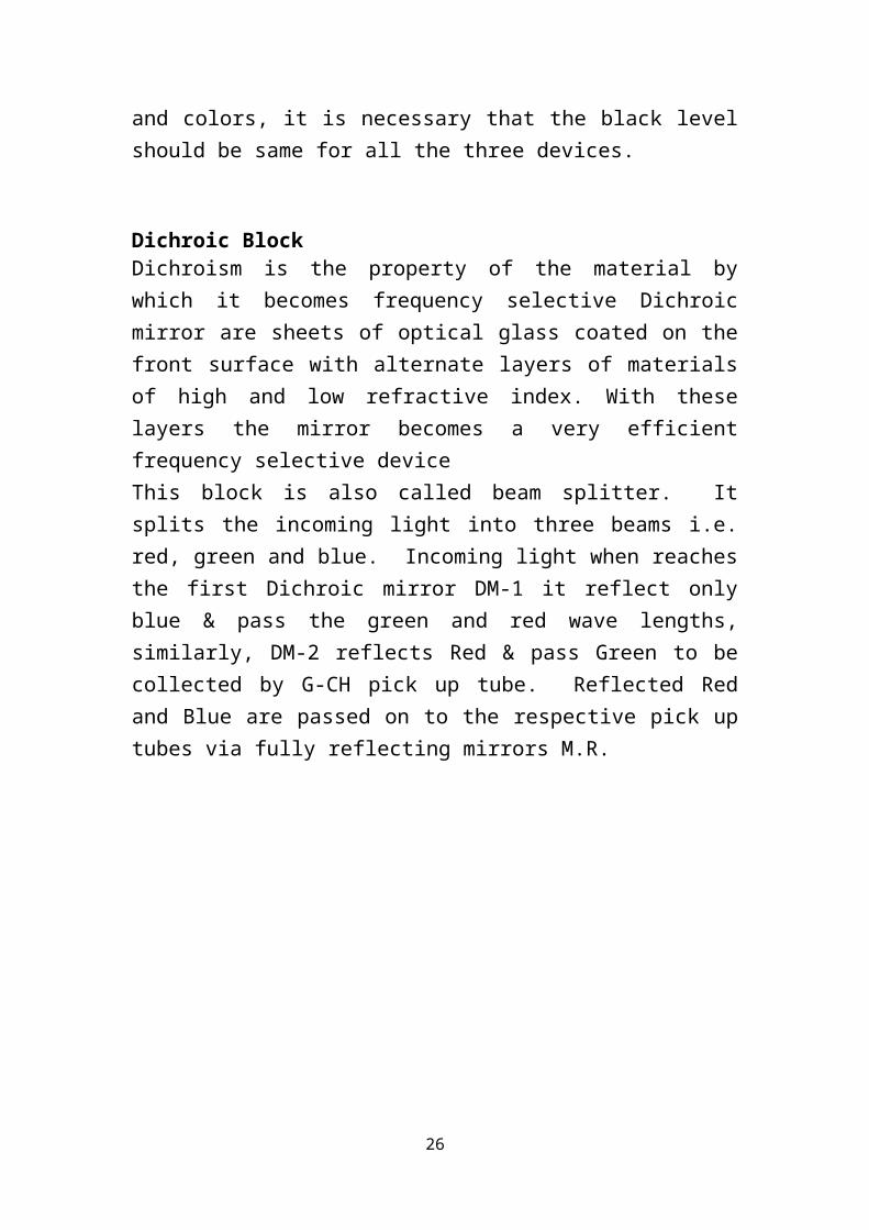
Dichroic BlockDichroism is the property of the material by which it becomes frequency selective Dichroic mirror are sheets of optical glass coated on the front surface with alternate layers of materials of high and low refractive index.
17

With these layers the mirror becomes a very efficient frequency selective deviceThis block is also called beam splitter. It splits the incoming light into three beams i.e. red, green and blue. Incoming light when reaches the first Dichroic mirror DM-1 it reflect only blue & pass the green and red wave lengths, similarly, DM-2 reflects Red & pass Green to be collected by G-CH pick up tube. Reflected Red and Blue are passed on to the respective pick up tubes via fully reflecting mirrors M.R.
Fig 3.8 Dichroic block
Transducer or Pick up Device: -The function of traducer or pick up device is to convert optical image into an electrical signal.
Types of Pick - Up Devices There are three types of pick up devices based on: Photo emissive material: These materials emit electrons when the light falls on them. Amount of emitted electrons depends on the light. These cameras are called image orthicon cameras. These cameras are bulky and need lot of light. These are no longer in use.
Photoconductive material: The conductivity of these material changes with amount of light falling on them. The material with variable conductivity is made part of an electrical circuit and the signal is thus recovered. First cameras based on this principle were Vidicon Cameras used in the monochrome telecine chain of
18

Doordarshan Kendras. As these cameras have serious Lag and other problems relating to dark currents, further improvement in these cameras led to the development of Plumbicon and Saticon Cameras.
Charge coupled devices: These semiconductor devices convert light into a charge image, which is collected at a high speed to form a signal.
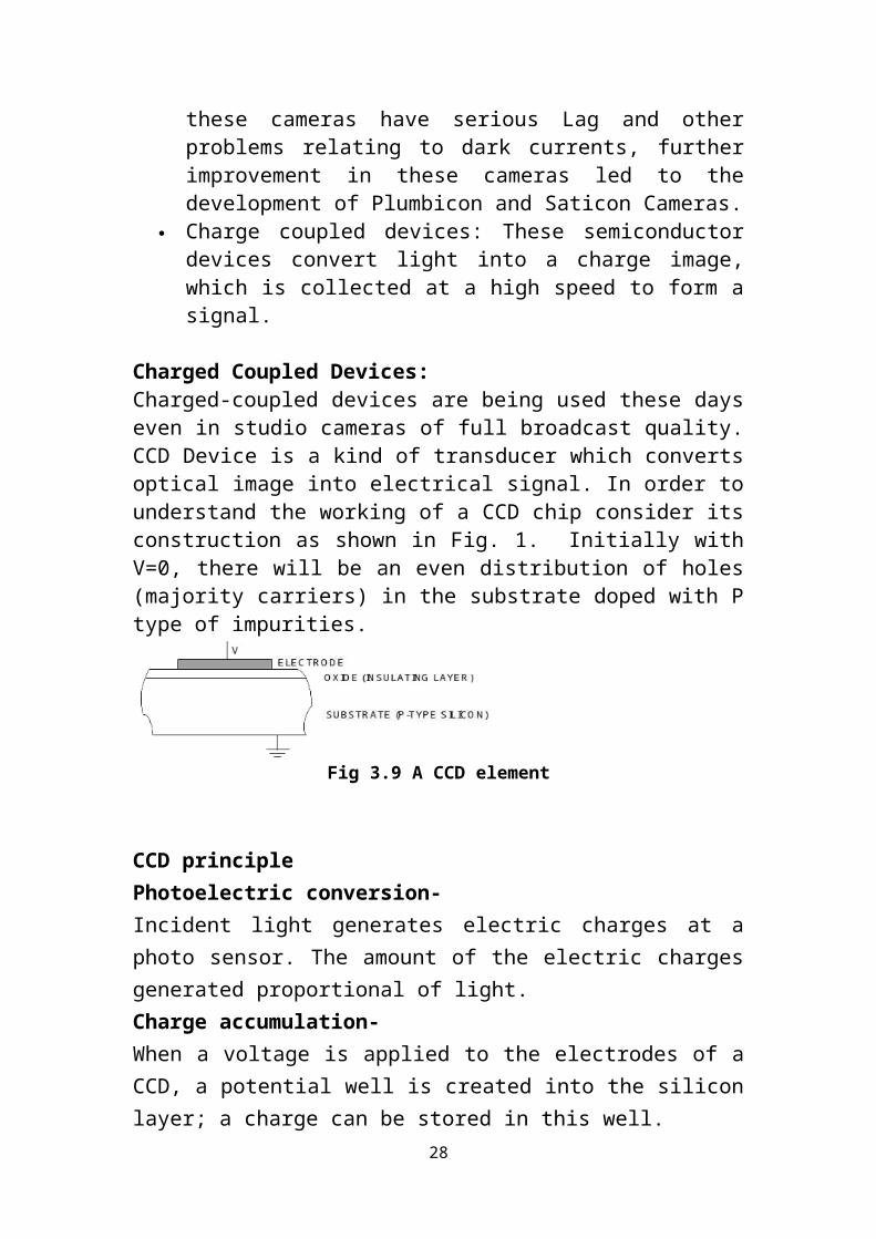
Charged Coupled Devices:Charged-coupled devices are being used these days even in studio cameras of full broadcast quality. CCD Device is a kind of transducer which converts optical image into electrical signal. In order to understand the working of a CCD chip consider its construction as shown in Fig. 1. Initially with V=0, there will be an even distribution of holes (majority carriers) in the substrate doped with P type of impurities.
Fig 3.9 A CCD element
CCD principlePhotoelectric conversion-Incident light generates electric charges at a photo sensor. The amount of the electric charges generated proportional of light.Charge accumulation-When a voltage is applied to the electrodes of a CCD, a potential well is created into the silicon layer; a charge can be stored in this well.Charge Transfer: -The depth of the potential well proportional to the applied voltage to the electrodes i.e. the higher the voltage applied to the electrodes, the deeper the potential well.
Types of CCD chipsThere are three different types of CCD chips used as a pick up device for CCD cameras, namely
19

Interline transfer type Frame transfer type Frame interline transfer type
Camera Electronics:-The signal system in most of the cameras consists of processing of the signal from Red, Green, & Blue CCD. The signal picked up from the target is amplified at the target itself in a stage called Pre-Pre amplifier. Then the signal goes to Pre-Processor PCB, where auto white balance and auto black balance adjustment done. Then gain control of 0,9,18db and flare compensation is done. Flare is the compensation where a light is reflected or dispersed due to the lens optical system or CCD surface, causing the black level to rise from the correct level. The black level fluctions or deterioration due to the lens characteristics is reduced by means of electrical compensation. When flare occurs the pictures contrast drop and areas which normally are black become colored. Then B/W shading compensation is done. Black shading performs the picture black shading compensation for the black level. The signal amplitude may not be constant when there is no light
known as black shading. The main cause of black shading is due to the temperature that changes the characteristics of the CCD.
Auto white shading performs the white shading compensation for the white level.
The signal amplitude is not constant even there is a fixed quantity of incandescent light known as white shading.
The cause of white shading is a drop in light quantity around the edges of the lens. Compensation of this drop makes the white level to be as flats as possible.
Then Pre gamma correction and pre Knee compensation is done during maximum input signal high level areas are compressed to prevent white spots.
GammaLinearity is maintained throughout the system from camera CCD to TV screen, in order to achieve correct luminance and color signal, most of the camera pick up devices have gamma nearly one, but as the TV picture Tube game is more than 1. To compensate this gamma correction is included in video processing stage in the camera. Gamma is increased, the effect on a picture is of stretching the whites and causing the blacks dark greys, when gamma is reduced, blacks are stretched.
20

Specification of a DVCPRO-50 camcorderPower Supply 12v, 24WPick up Device 2/3 inch 3 CCDPixels 5,20,000 or 6,00,000.Quantization DVCPRO 50 DVCPRO 25 12bit/18 MHZ 10bit/18MHZ S/N ratio 62 dbVTR sectionAnalog component out Y=25 to 5.75 MHZ Pb/Pr=25to 2,75MHZS/n ratio =55dbAudio sampling frequency =48 KHZQuantization =16bitTape speed DVCPRO25= 33.854mm/sec DVCPRO50= 67.708mm/sec Some Important Terms Related to Video camera
The process of adjustment provided in the camera by means of which the level of the lowest luminance part of the scene under consideration is maintained at predetermined black level.
ABL –Automatic Black level Aperture Correction- It is the correction provided in the video processing stage of a
camera by means of which high frequency losses are compensated by boosting certain high frequencies. With the help of aperture correction, , sharpness of the image is increased.
back focus The distance between last glass surface of the lens and image plane
is varied during this adjustment. Band Width The complete range of frequency over which the TV system can
function. Black Balance
Each pick up devices gives some signal even when lens is capped. For correct reproduction of tones and colors, it is necessary that this black level should be same for all the three pickup devices {R,G,B}
21

Black Burst A signal which contains s mixed sync {H&V} and burst. Black Level Dc level of back porch Burst Burst is provided from small sections 10 cycles of 4.43 MHz
subcarrier wave is transmitted separately as the reference for the color information. It is placed near the end of horizontal blanking.
Detail Enhancement It improves picture quality by raising contrast of light to dark, dark
to light transitions, making edges of object appear sharper, both horizontally and vertically.
Encoded signal:- signal with three different color signals (R,G,B) are transformed
into samr form of modulation of a subcarrier and are added into the luminance signal .The form of modulation varies with the color system.
Flare: Flare is a light from the scene, which ultimately arrives at the CCD unrelated to its original position in the scene It is due to the internal reflections within the optical system.
Frequency response The amplitude of a video signal over a range of frequencies. Gamma: The mathematically relationship of the input signal to the
output signal is known as gamma. For linear relationship gamma is one. Gamma of a system decides over all tonal reproduction of video pictures
Genlock The technique for to locking together the output signal from 2 or
more video sources are known as genlock Sensitivity IT represents the lover limit of brightness under which the object
can be perceived i.e. brightness or the iris position necessary for satisfactory obtaining a video signal with a sufficient level.
Resolution It defines smallest picture elements that can be resolved by the
system. S/N Ratio
22
Ratio of amplitude of the wanted signal to the unwanted noise in an electrical system
3.5 COMPUTER SECTION (CS):
CS is responsible for maintenance of all the computers and computer related hardware, software and programs. They are responsible for the proper functioning of all the computers at work in the station.
CS has the following group of computers: non linear editing system character generator video server video logger BDL news clip mail system
In addition to above specialized Computers, we have a lot of PCs. Maintenance of both the hardware and the software, of all the computers is also carried by Computer Maintenance section.Non linear editing systems:
Five Nos. of NLEs in working condition Two kind of operating system used in NLEs
DPS (operated on windows) FCP (operated on MAC)Non linear video editing is the process by which we can access any single frame in a video clip with the same ease as any other. Video and audio are first captured to hard disk, or other storage device, then edited on a computer using any of a wide range of software.
DPS velocity/final cut pro:
Non linear editing software Used to interface captured video to digitize it Wide range of audio and video formats supported Wide range of pre made transitions and effects are available Has various output options including DVD and web distribution
and playing or printing to video tapes
23

Advantages of NLE:
Flexibility in all editing functions Easy to do changes, undo, copy, duplicate & multiple version Easy operation for cut, dissolve, wipes and other transition
effects Multilayering of video is easy Powerful integration of video and graphics. Tools for filtering,
color correction, key framing & special 2D/3D effects Equally powerful audio effects and mixing Possible to trim, compress or expand the length of the clip Support for multi format , multi resolution clips Intelligent and powerful 3D video effect can be created and
customized Efficient and intelligent storage
Character generator: These are mainly used to super-impose text on video All CG’s are connected with server, used for dumping CG’S are used to generate the detail of the sport in sport event
broadcasting
Five character generators are available in DDK Jalandhar 2 used in graphics section 2 used in OB section 1 is used in Earth Station
Video server:
LEITCH Make VR445 is used as a broadcast digital video server Based on MPEG-2 standard, used by most of broadcasting industry Capable of supporting interlaced fields, 16:9 ratio video and is a
step forward to HDTV VR445 provides integration of insertion , packaging and
transmission functions Acts as fiber channel host for storage of array modules, holding
upto 65 hours of storage at 8MB/s of MPEG-2 format
24

Supports multiple compression format MOS protocol enable browsing, viewing and rundown playback
Video logger:
Provided in the Earth Station to record and store programs relayed by DD Punjabi
Records in MPEG-1 format Can store programs for 90 days continuously Have playback facility
BDL news teleprompter:
2 computers are used for it One is in NEWS room, where news is compiled and edited in the
text form Another computer is available in PCR, these are networked to each
other By giving proper command , final news can be sent to the
teleprompter for reading by the news-reader in studio Speed of the news can be controlled by the news-reader with the
help of remote provided on the news desk It is a display device that prompts the person with an electronic
visual text of speech or script It is similar to using cue cards Screen is in the front of the lens of the camera and words on the
screen are reflected to eyes of the speaker using one way mirror
Clip mail system: Used for receiving news from Chandigarh and Patiala through ISDN phone lines. Work on Win 2000 operating system having Matrox Perhelia card, which is backbone of the system. System at Jalandhar and Chandigarh are used to send and receive the news System at Patiala can only send the news.
PC’S: 21 PCs in technical area 20 PCs in Administration section.
All being maintained by computer section
25
3.6 XTR:
Transmitter of DDK Jalandhar is located at Khurla Kingra. IT is used to transmit DD National and DD News. Channel 9 is for DD National and channel 22 is for DD News. The signal is received by the receivers mark III and is modulated and transmitted through the transmitting tower. The transmission process is VSB(Vestigial Side band) transmission.
Transmitting tower details:
212 meter in height One of the highest tower in North India and also all over India Antenna type: Dipole antenna, omnidirectional
Equipments in transmitting station:
Receiving rack for DD national and DD news Power supply Air conditioning Air Cooling vents Data cables( usually co-axial cables) Transformers, stabilizers etc
The frequency band for DD national and DD News are 202-209MHz and 478-486MHz.
The audio signal is frequency modulated and video signal is amplitude modulated(negative am)
Negative modulation:The increase in picture brightness causes reduction in carrier amplitude i.e. the carrier amplitude will be maximum corresponding to sync tip and minimum corresponding to peak white.
In television though positive modulation was adopted in initial stages, negative modulation is generally adopted (PAL’B uses negative modulation) now a days, as there are certain advantages over positive modulation.
Advantages of Negative Modulation
26

Impulse noise peaks appear only in black region in negative modulation. This black noise is less objectionable compared to noise in white picture region.
Best linearity can be maintained for picture region and any non-linearity affects only sync which can be corrected easily.
The efficiency of the transmitter is better as the peak power is radiated during sync duration only (which is about 12% of total line duration).
The peak level representing the blanking or sync level may be maintained constant, thereby providing a reference for AGC in the receivers.
In negative modulation, the peak power is radiated during the sync-tip. As such even in case of fringe area reception, picture locking is ensured, and derivation of inter carrier is also ensured.
Vestigial side band transmission:Another feature of present day TV Transmitters is vestigial side band transmission. If normal amplitude modulation technique is used for picture transmission, the minimum transmission channel bandwidth should be around 11 MHz taking into account the space for sound carrier and a small guard band of around 0.25MHz. Using such large transmission BW will limit the number of channels in the spectrum allotted for TV transmission. To accommodate large number of channels in the allotted spectrum, reduction in transmission BW was considered necessary. The transmission BW could be reduced to around 5.75 MHz by using single side band (SSB) AM technique, because in principle one side band of the double side band (DSB) AM could be suppressed, since the two side bands have the same signal content.It was not considered feasible to suppress one complete side band due to difficulties in ideal filter design in the case of TV signal as most of the energy is contained in lower frequencies and these frequencies contain the most important information of the picture. If these frequencies are removed, it causes objectionable phase distortion at these frequencies which will affect picture quality. Thus as a compromise only a part of lower side band is suppressed while taking full advantage of the fact that:
27
Visual disturbance due to phase errors are severe and unacceptable where large picture areas are concerned (i.e. at LF) but
Phase errors become difficult to see on small details (i.e. in HF region) in the picture. Thus low modulating frequencies must minimize phase distortion where as high frequencies are tolerant of phase distortions as they are very difficult to see.
The radiated signal thus contains full upper side band together with carrier and the vestige (remaining part) of the partially suppressed LSB. The lower side band contains frequencies up to 0.75 MHz with a slope of 0.5 MHz so that the final cut off is at 1.25 MHz.
3.7 EARTH STATION:The Earth Station is providing quality service of DD Punjabi with very low rate of interruptions and breakdowns. Satellite Modulators of Tandberg SM 5600 have been installed in E/S since December 2003. Power supply modules of these units are erratic. These modules are required to be procured on priority bases to keep DD Punjabi channel service smooth.Inaugurated on 6th ,August 1998 by Smt. Sushama Swaraj, I&B Minister.
28
Fig 3.10 Inside earth station
Service of ES at DDK Jalandhar: To uplink programs of DD Punjabi and DD feed This E/S is providing signal to following HPTs and LPTs in Punjab
for telecasting regional service of DDK Jalandhar HPTs Amritsar, Bhatinda & Fazilka LPTs Abohar, Chandigarh, Ferozepur, Gurdaspur, Pathankot &
Patiala.
Parameters of Satellite For DD-Punjabi Service:
Satellite Insat 3A , 93.5 degree East Transponder C-01 MCPC Uplink Freq. 5965.5 MHz ,Pol. H Down link freq. 3740.5 MHz, Pol. V Symbol Rate 6.25 Mbps
Subsystems of ES:
29
PDP Base band rack Compression rack Receive monitoring rack HPA rack PDA
Base band rack (E/S):
• Fiber optic receiver to receive embedded signal from studio(CAR)• Signal generator• Audio level monitor• Video monitor
Fig 3.11 Base Band Rack
Compression rack (E/S):• Encoders• Multiplexer• Modulator• Redundancy switch• NMS
HPA rack ( E/S): HPA
30

Dehydrator Waveguide
Rx monitoring rack( E/S):
UP converter RF power divider C to L band converter I. R .D. Spectrum Analyzer
Fig 3.12 Block Diagram of ES DDK Jalandhar
Above is the complete block diagram of the digital earth station DDK Jalandhar.
UPS and batteries are also available for backups:
31

UPS: Series 7400 of make Tata Liebert Limited has been provided for
continuous PS to E/S and Play Back Booth. UPS is of 40+40 kVA capacity with 3 Hrs back up .
Batteries:
For sufficient back up UPS is supported by 64 no.Suntech SMF Batteries of
12V, 42 Ah capacities each.
Up gradation of earth station:
In December 2003 the transmission was shifted to digital mode as simulcast, DD-Punjabi and Jalandhar feed.
4. CONCLUSION AND FUTURE WORK:
32
Conclusion:The training was a good learning experience professionally and technically. The professionally we learn how things work in an office and how to carry oneself professionally. We learn different technicalities about the whole broad casting processes which involves from how a studio works to how the programme recorded in studio is broadcasted.The curiosity about the process of broadcasting is fulfilled through this training. Personally this training made me more confident and made me believe that I will be able to work in any environment.This report gives the overview of all the processes and functioning of DDK Jalandhar in broadcasting .
Scope of future work:There are many scope of improvement in the different sections of in the near future:
Non linear editing will be implemented more than now in the near future.
XTR will be able to transmit more channels than now. Almost all the sections will be fully digitalized in the future. OB van will be more equipped than now. Studio’s will me more equipped than now.
REFERENCES:
Material provided by the training engineer
33

http://en.wikipedia.org/wiki/Broadcasting#Types_of_broadcasting http://www.accwll.com/articles/what-are-different-types-
broadcasting-systems http://engineers.ddkjalandhar.com/ http://www.ddpunjabi.in/
34