reconstruction of the optical system of the human eye...
TRANSCRIPT

Reconstruction of the Optical System of the Human Eye with Reverse Ray-Tracing
Alexander V. Goncharova, Maciej Nowakowski a, Matthew T. Sheehanb, and Christopher Daintyb
aDepartment of Experimental Physics, National University of Ireland, Galway, Ireland [email protected], [email protected], [email protected]
bOptometry Department, School of Physics, Dublin Institute of Technology, Dublin, Ireland [email protected]
Abstract: We present a practical method for reconstructing the optical system of the human eye from off-axis wavefront measurements. A retinal beacon formed at different locations on the retina allows probing the optical structure of the eye by the outgoing beams that exit the eye through the dilated pupil. A Shack-Hartmann aberrometer measures the amount of wave aberrations in each beam at the exit pupil plane. Wavefront data obtained at different oblique directions is used for tomographic reconstruction by optimizing a generic eye model with reverse ray-tracing. The multi-configuration system is constructed by tracing pre-aberrated beams backwards from each direction through the exit pupil into the optical system of the aberrometer followed by the generic eye model. Matching all wave aberrations measured at each field point is equivalent to minimizing the size of the beacon spots on the retina. The main benefit of having a personalized eye model is the ability to identify the origin of the ocular aberrations and to find the optimal way for their correction.
!2008 Optical Society of America OCIS codes: (170.4460) Ophthalmic Optics; (330.5370) Physiological optics; (330.7310) Vision; (010.1080) Adaptive Optics.
References and links 1. M. Born and E. Wolf, Principles of Optics, 7th ed. (Cambridge U. Press, Cambridge, UK, 1999). 2. L. Thibos, R. A. Applegate, J. T. Schwiegerling, and R. Webb, “Standards for reporting the optical aberrations
of eyes,” in Vision Science and its Applications, OSA Technical Digest, paper SuC1 (2000). 3. J. Stone, P. H. Hu, S. P. Mills, and S. Ma, "Anisoplanatic effects in finite-aperture optical systems," J. Opt. Soc.
Am. A 11, 347-357 (1994). 4. M. Di Jorio, "The general theory of isoplanatism for finite aperture and field," J. Opt. Soc. Am. 39, 305-319
(1949). 5. A. V. Goncharov and C. Dainty, “Wide-Field Schematic Eye Model with Gradient-Index Lens,” J. Opt. Soc.
Am. A 24, 2157-2174 (2007). 6. F. Rigaut, B. L. Ellerbroek, and M. J. Northcott, "Comparison of curvature-based and Shack Hartmann-based
adaptive optics for the Gemini telescope," Appl. Opt. 36, 2856-2868 (1997). 7. M. Nicolle, T. Fusco, G. Rousset, and V. Michau, "Improvement of Shack-Hartmann wave-front sensor
measurement for extreme adaptive optics," Opt. Lett. 29, 2743-2745 (2004). 8. A. V. Goncharov, J. C. Dainty, and S. Esposito, "Compact multireference wavefront sensor design," Opt. Lett.
30, 2721-2723 (2005). 9. T. W. Nicholls, G. D. Boreman, and J. C. Dainty, "Use of a Shack-Hartmann wave-front sensor to measure
deviations from a Kolmogorov phase spectrum," Opt. Lett. 20, 2460-2462 (1995). 10. T. M. Jeong, M. Menon, and G. Yoon, "Measurement of wave-front aberration in soft contact lenses by use of a
Shack-Hartmann wave-front sensor," Appl. Opt. 44, 4523-4527 (2005). 11. J. -S. Lee, H. -S. Yang, and J. -W. Hahn, "Wavefront error measurement of high-numerical-aperture optics with
a Shack-Hartmann sensor and a point source," Appl. Opt. 46, 1411-1415 (2007). 12. J. Liang, B. Grimm, S. Goelz, and J. F. Bille, "Objective measurement of wave aberrations of the human eye
with use of a Hartmann-Shack wave-front sensor," J. Opt. Soc. Am. A 11, 1949-1957 (1994).
#88818 - $15.00 USD Received 19 Oct 2007; revised 15 Jan 2008; accepted 21 Jan 2008; published 24 Jan 2008(C) 2008 OSA 4 February 2008 / Vol. 16, No. 3 / OPTICS EXPRESS 1692

13. T. O. Salmon, L. N. Thibos, and A. Bradley, "Comparison of the eye's wave-front aberration measured psychophysically and with the Shack-Hartmann wave-front sensor," J. Opt. Soc. Am. A 15, 2457-2465 (1998).
14. R. G. Lane and M. Tallon, "Wavefront reconstruction using a Shack-Hartmann sensor," Appl. Opt. 31, 6902-6908 (1992).
15. R. C. Cannon, "Global wave-front reconstruction using Shack-Hartmann sensors," J. Opt. Soc. Am. A 12, 2031-2039 (1995).
16. M. T. Sheehan, A. V. Goncharov, V. M. O'Dwyer, V. Toal, and C. Dainty, "Population study of the variation in monochromatic aberrations of the normal human eye over the central visual field," Opt. Express 15, 7367-7380 (2007).
17. J. Lee, R. V. Shack, and M. R. Descour, "Sorting method to extend the dynamic range of the Shack-Hartmann wave-front sensor," Appl. Opt. 44, 4838-4845 (2005).
18. R. Navarro, L. González, and J. L. Hernández-Matamoros, “On the prediction of optical aberrations by personalized eye models,” Optom. Vision Sci. 83, 371–381 (2006).
19. M. Ye, X. X. Zhang, L. N. Thibos, and A. Bradley,“A new single-surface model eye that accurately predicts chromatic and spherical aberrations of the human eye,” Invest. Ophthalmol. Visual Sci. 34, 777 (1993).
20. W. Lotmar, “Theoretical eye model with aspherics,” J. Opt. Soc. Am. 61, 1522-1529 (1971). 21. A. C. Kooijman, “Light distribution on the retina of a wide-angle theoretical eye,” J. Opt. Soc. Am. 73, 1544–
1550 (1983). 22. J. W. Blaker, “Toward an adaptive model of the human eye,” J. Opt. Soc. Am. 70, 220–223 (1980). 23. R. Navarro, J. Santamaria, and J. Bescos, “Accommodation-dependent model of the human eye with aspherics,”
J. Opt. Soc. Am. A 2, 1273–1281 (1985). 24. I. Escudero-Sanz and R. Navarro, “Off-axis aberrations of a wide-angle schematic eye model,” J. Opt. Soc. Am.
A 16, 1881–1891 (1999). 25. G. Smith, D. A. Atchison, and B. K. Pierscionek, “Modeling the power of the aging human eye,” J. Opt. Soc.
Am. A 9, 2111–2117 (1992). 26. I. H. Al-Ahdali and M. A. El-Messiery, "Examination of the effect of the fibrous structure of a lens on the
optical characteristics of the human eye: a computer-simulated model," Appl. Opt. 34, 5738-5745 (1995). 27. H.-L. Liou and N. A. Brennan, “Anatomically accurate, finite model eye for optical modeling,” J. Opt. Soc. Am.
A 14, 1684–1695 (1997). 28. S. Barbero, "Refractive power of a multilayer rotationally symmetric model of the human cornea and tear film,"
J. Opt. Soc. Am. A 23, 1578-1585 (2006). 29. J. A. Sakamoto, H. H. Barrett, and A. V. Goncharov, “Inverse optical design of the human eye using likelihood
methods and wavefront sensing”, Opt. Express 16, 304-314 (2008). 30. L. Lundström, J. Gustafsson, I. Svensson, and P. Unsbo, “Assessment of objective and subjective eccentric
refraction,” Optom. Vis. Sci. 82, 298-306 (2005). 31. R. Navarro, L. González, and J. L. Hernández, “Optics of the average normal cornea from general and canonical
representations of its surface topography, ” J. Opt. Soc. Am. A 23, 219-232 (2006). 32. Llorente, L., S. Barbero, D. Cano, C. Dorronsoro, and S. Marcos, “Myopic versus hyperopic eyes: axial length,
corneal shape and optical aberrations,” Journal of Vision. 4, 288 (2004), http://journalofvision.org/4/4/5/. 33. L. Llorente, S. Marcos, C. Dorronsoro, and S. A. Burns, “Effect of sampling on real ocular aberration
measurements, ” J. Opt. Soc. Am. A 24, 2783-2796 (2007). 34. B. Pierscionek, R. J. Green, and S. G. Dolgobrodov, “Retinal images seen through a cataractous lens modeled as
a phase-aberrating screen, ” J. Opt. Soc. Am. A 19, 1491-1500 (2002). 35. R. Navarro, F. Palos, and L. González, “Adaptive model of the gradient index of the human lens. I. Formulation
and model of aging ex vivo lenses, ” J. Opt. Soc. Am. A 24, 2175-2185 (2007). 36. A. Dubinin, A. Belyakov, T. Cherezova, and A. Kudryashov “Anisoplanatism in adaptive compensation of
human eye aberrations”, in Optics in Atmospheric Propagation and Adaptive Systems VII, J. D. Gonglewski and K. Stein Eds., Proc SPIE 5572, 330-339 (2004).
37. J. Tabernero, A. Benito, E. Alcón, and P. Artal, “Mechanism of compensation of aberrations in the human eye, ” J. Opt. Soc. Am. A 24, 3274-3283 (2007).
38. S. Bará and R. Navarro, “Wide-field compensation of monochromatic eye aberrations: expected performance and design trade-offs,” J. Opt. Soc. Am. A 20, 1-10 (2003).
39. P. A. Bedggood, R. Ashman, G. Smith, and A. B. Metha, “Multiconjugate adaptive optics applied to an anatomically accurate human eye model,” Opt. Express 14, 8019-8030 (2006).
40. B. Tan, Y. -L. Chen, K. Baker, J. W. Lewis, T. Swartz, Y. Jiang, and M. Wang, “Simulation of realistic retinoscopic measurement," Opt. Express 15, 2753-2761 (2007).
41. A. Roorda, M. C. W. Campbell, and W. R. Bobier, “Geometrical theory to predict eccentric photorefraction intensity profiles in the human eye,” J. Opt. Soc. Am. A 12, 1647-1656 (1995).
42. Y. -L. Chen, B. Tan, and J. Lewis, “Simulation of eccentric photorefraction images," Opt. Express 11, 1628-1642 (2003).
43. P. A. Piers, N. E. Sverker Norrby, and U. Mester, “Eye models for the prediction of contrast vision in patients with new intraocular lens designs,” Opt. Lett. 29, 733-735 (2004).
44. J. Tabernero, P. Piers, and P. Artal, “Intraocular lens to correct corneal coma,” Opt. Lett. 32, 406-408 (2007). 45. D. A. Atchison, “Aberrations associated with rigid contact lenses,” J. Opt. Soc. Am. A 12, 2267-2273 (1995).
#88818 - $15.00 USD Received 19 Oct 2007; revised 15 Jan 2008; accepted 21 Jan 2008; published 24 Jan 2008(C) 2008 OSA 4 February 2008 / Vol. 16, No. 3 / OPTICS EXPRESS 1693
46. H. H. Dietze and M. J. Cox, “Correcting ocular spherical aberration with soft contact lenses,” J. Opt. Soc. Am. A 21, 473-485 (2004).
47. D. Vazquez, E. Acosta, G. Smith, and L. Garner, "Tomographic method for measurement of the gradient refractive index of the crystalline lens. II. The rotationally symmetrical lens," J. Opt. Soc. Am. A 23, 2551-2565 (2006).
48. B. A. Moffat, D. A. Atchison, and J. M. Pope, "Aged-related changes in refractive index distribution and power of the human lens as measured by magnetic resonance microimaging in vitro," Vision Res. 42, 1683-1693 (2002).
49. S. A. Burns, S. Marcos, A. E. Elsner, and S. Bara, “Contrast improvement of confocal retinal imaging by use of phase-correcting plates," Opt. Lett. 27, 400-402 (2002).
50. J. Arines and S. Bara, “Hybrid technique for high resolution imaging of the eye fundus, ” Opt. Express 11, 761-766 (2003).
51. J. M. Bueno, J. J. Hunter, C. J. Cookson, M. L. Kisilak, and M. C. W. Campbell, “Improved scanning laser fundus imaging using polarimetry, ” J. Opt. Soc. Am. A 24, 1337-1348 (2007).
52. L. E. Marchese, R. Munger, and D. Priest, "Wavefront-guided correction of ocular aberrations: Are phase plate and refractive surgery solutions equal?," J. Opt. Soc. Am. A 22, 1471-1481 (2005).
1. Introduction The imaging quality of any optical system can be characterized in terms of wave aberrations, which are usually expanded into orthonormal Zernike functions defined over a circular aperture [1]. In order to express the wavefront as a set of discrete aberrations, one needs to estimate Zernike coefficients. In visual optics, there is a standard for arranging Zernike functions and their coefficients [2]. A set of Zernike coefficients indicates the amount of various aberration types present in the wavefront for a given direction that corresponds to a single field point. As a rule, aberrations vary across the field, therefore one needs to use different sets of Zernike coefficients to describe each isoplanatic patch of the field. In astronomy, the latter is usually defined as an area of the field where the variation of the root-mean-square (RMS) wavefront error between any two points does not exceed 1 rad [3]. We shall use this definition of the isoplanatic patch. Rotationally symmetric optical systems exhibit symmetric distribution of field aberrations that can be characterized in annular zones of the field [4], whereas for the optical systems that lack any type of symmetry, e.g. the human eye, the characterization of image quality involves larger number of field points. Knowing the isoplanatic patch could help to find the optimal number of reference points required for modeling the imaging properties of the system. In the case of system reconstruction, one should position the probing sources within the angular distance comparable with the size of the isoplanatic patch. Once the field aberrations are known, the major factors limiting optical performance can be identified and in some cases their origin can be understood, which in turn could assist finding the best possible way for image enhancement. Another advantage of obtaining a detailed description of wave aberrations across the field is the ability to reconstruct the unknown optical parameters of the system. The number of reference field points necessary for such tomographic reconstruction can be greatly reduced if some prior knowledge is available for the system under consideration. The human eye is a good example of the optical system with prior knowledge on its typical structure, which is represented by age-dependent generic eye models [5]. The latter can be optimized to fit the measured wave aberrations at all reference points in the field. Optimization allows one to reconstruct a subject-specific eye model, which accurately predicts aberrations at the reference field points as well as within the whole field. Reconstruction of a full set of optical parameters of the eye is a more economical description of field aberrations than the large number of sets of Zernike coefficients required for wide fields.
The main goal of this paper is to present a method of reconstructing the optical system of the eye from wavefront measurements obtained within the central part of the visual field.
#88818 - $15.00 USD Received 19 Oct 2007; revised 15 Jan 2008; accepted 21 Jan 2008; published 24 Jan 2008(C) 2008 OSA 4 February 2008 / Vol. 16, No. 3 / OPTICS EXPRESS 1694

2. The principle of reconstructing the optical system of the eye with reverse ray-tracing The Shack-Hartmann (SH) wavefront sensor is widely used in astronomical adaptive optics [6-8], atmospheric optics [9], optical testing and metrology [10,11], and more recently in ophthalmology [12,13] for measuring wavefront distortions [14,15]. We have incorporated the SH wavefront sensor in our aberrometer in order to study the variation of the ocular aberrations in the central visual field [16]. The optical layout of the wavefront sensing arm of the aberrometer is presented in Fig.1. A laser diode (emitting light at wavelength "=677 nm) in conjunction with a lens forms a collimated beam (shown in red), which after passing through a pinhole enters the eye and generates a reference source on the retina. The pinhole is decentred so that the beam enters the eye near the center of the pupil without producing any visible back reflection. The outgoing beam (shown in blue) probing the optical structure of the eye passes through a fully dilated pupil and then enters the sensing arm in the aberrometer. A Badal system accompanied by re-imaging identical doublets that conjugate the pupil with a lenslet array, where the distortion of the beam is measured. The eye fixates at different points in the field by viewing a fixation target at an oblique angle (up to 5 deg) with respect to the optical axis of the aberrometer.
4 3 2 1
6 5
7 8 9
10 11 12 13
Fig. 1. The optical layout of the aberrometer: 1 – laser diode, 2 – pinhole, 3 – focusing lens, 4 – visual target, 5 – collimating lens, 6 – human eye, 7 – pellicle beamsplitter, 8 – Badal focusing lens, 9 – Badal pick-off mirrors, 10 – Badal collimating lens, 11,12 – pupil re-imaging lenses, 13 – exit pupil (lenslet array).
The axial position of the flat mirrors in the Badal system is adjusted to remove the best sphere (defocus term) in the central beam. This is a simple way to increase the dynamic range of the SH wavefront sensor without introducing any noticeable intrinsic aberrations into the measurements thanks to the ability of the achromatic doublet 8 to operate well in slightly converging or diverging beams. Additionally, the lenslet array together with the CCD is rotated at 45 degrees to the horizontal meridian of the eye, since it is anticipated that in the majority of cases astigmatism will be at meridians typically close to either 0 or 90 degrees. This helps to extend the dynamic range of the SH sensor for astigmatism; there are other methods to enlarge the dynamic range [17]. The square lenslet array provides 16 subapertures across a 6-mm beam. The wavefront aberrations measured by the SH sensor at the exit pupil are converted into 20 Zernike terms (up to the 5th order). Simultaneous imaging of the iris edge via the IR channel enables us to determine the pupil center independent of the SH spot
#88818 - $15.00 USD Received 19 Oct 2007; revised 15 Jan 2008; accepted 21 Jan 2008; published 24 Jan 2008(C) 2008 OSA 4 February 2008 / Vol. 16, No. 3 / OPTICS EXPRESS 1695

position. The series of wavefront measurements obtained for different fixation positions of the eye form the basis for reconstructing the optical parameters of the eye. Figure 2 schematically depicts the coverage of the central field by five probing beams (color scale given in microns).
Fig. 2. Schematic optical layout of the human eye with five probing beams and corresponding phase maps of measured wave aberrations shown in color. The angle between A and B points is 10 degrees.
The main principle of reconstructing the optical system of the eye is schematically shown
in Fig. 3. The probing beam created from a reference source on the retina exits the eye and traverses the aberrometer sensing arm until it reaches the exit pupil, where the lenslet array is replaced by an imaginary phase plate. The phase plate with its shape derived from the SH sensor measurements plays a role of a corrector that transforms the aberrated wavefront into a flat wavefront. Due to reciprocity of propagation of light a collimated beam entering the phase plate from the opposite direction, as can be seen in Fig. 3 (b), becomes pre-aberrated so that it will be focused into a compact spot by the optical system of the eye. The spot spread is defined by the angular extend of the reference source, which is assumed to be unresolved and comparable in size with a diffraction-limited spot of a 1.5 mm beam focused on the retina. The condition of achieving a compact spot in the image is one of the common optimization criteria well-presented in optical design programs, such as OSLO, Zemax and Code V, which one could use to recover the missing optical parameters of the eye model. Initially we start with a generic eye model, which is optimized into a subject-specific model. Fulfilling the condition of minimal spot size simultaneously for on-axis and off-axis beams as shown in Fig. 3 (b), enables reconstruction of the optical structure of the eye. Using several beams at oblique angles helps to discern the optical parameters owing to their different involvement in the focusing of the off-axis beams. For example, the front surface of the cornea and the posterior surface of the crystalline lens are located at some distance from the pupil, hence they will cause field-varying aberrations, whereas the anterior surface of the lens can only be responsible for ocular aberrations that are constant across the field. Obviously the larger the angle between the probing beam the better coverage of the marginal areas of the optical surface will be. This in turn makes it easier to disentangle the interrelated optical parameters that give almost identical contributions to the aberration in the axial beam. For example, changing the asphericity of the front corneal surface might lead to a similar reduction in ocular spherical aberrations as that produced by reshaping the lens structure alone. This ambiguous nature of ocular aberrations limits the effectiveness of the reconstruction with one axial beam [18]. The availability of the off-axis measurements does not always guarantee success in the reconstruction process. Major difficulties arise from the unknown distribution of the refractive index in the crystalline lens and the variability of the tear film profile. The impact of the tear film can be reduced by
#88818 - $15.00 USD Received 19 Oct 2007; revised 15 Jan 2008; accepted 21 Jan 2008; published 24 Jan 2008(C) 2008 OSA 4 February 2008 / Vol. 16, No. 3 / OPTICS EXPRESS 1696

taking several measurements for each direction and then selecting the most consistent data that corresponds to a more representative state of the tear film. The general strategy for optimizing the optical parameter in the generic eye model with a gradient index (GRIN) lens is presented in the next section.
(a)
(b)
(a)
(b)
Fig. 3. The principle of reconstructing the optical system of the eye with reverse ray tracing. 3. Optimization of the generic eye model Constructing an average (generic) model of the human eye is very difficult task due to considerable variations in the reported data of the dimensions and refractive index of the crystalline lens. The optical parameters of the eye, including the radii of curvatures and asphericities of the surfaces, their relative position and orientation, and the index of refraction of different media show some changes with age. There are also differences associated with ethnicity and gender. The magnitude of ocular aberrations is affected by the degree of accommodation of the lens and the pupil size defined by the iris radius. In spite of large inter-subject variability, benefits are still possible from using a generic model as a starting design for deriving a personalized eye model under certain assumption about the age and the accommodation state. For aged eyes with cataracts present in the crystalline lens, non-invasive methods to measure ocular aberrations might not be applicable. There have been a large number of eye models developed to study the optical performance of the human eye. Each model is usually suitable for modeling only one particular feature, for example spherical and chromatic aberration [19], astigmatism [20], light distribution on the retina [21], accommodation [22,23], off-axis aberrations [24], aging effects [25], anatomical structure of the crystalline lens [26,27]. Using our previous work on wide-field eye models with a gradient index lens [5], which also include aging effects, we start with the following model for a typical 30-year old eye. Figure 4(a) shows the optical layout of the generic eye model featuring an unaccommodated state. The optical parameters of the model are presented in Table 1.
#88818 - $15.00 USD Received 19 Oct 2007; revised 15 Jan 2008; accepted 21 Jan 2008; published 24 Jan 2008(C) 2008 OSA 4 February 2008 / Vol. 16, No. 3 / OPTICS EXPRESS 1697

r1 r2 r3 r4 r5
(b) (a) d1 d2 d3 d4
Fig. 4. The optical layout of the generic eye model with a gradient index lens made in Zemax (a), the fixation points in the central visual field used for eye modeling (outer and inner circles are 10 and 6 deg in diameter, respectively).
Table 1. Dimensions and refractive indices of the unaccommodated generic eye model Radius Conic constant Thickness Refractive index Medium r1 = 7.76 c1 = #0.1 d1 = 0.55 n1 = 1.3721 cornea r2 = 6.52 c2 = #0.3 d2 = 3.06 n2 = 1.33215 aqueous r3 = 11.51 c3 = #1 d3 = 3.69 n3 = 1.361…1.401* lens r4 = #7.67 c4 = 0.5 d4 = 16.6 n4 = 1.33224 vitreous r5 = #12.0 c5= 0 * Gradient index is defined as a function of the radial distance r and the lens thickness z
2 4 2 3 4( , ) 1.361 0.0021490 0.0000106 0.049467 0.015958 0.0001715 0.000141n r z r r z z z z= # # + # + +
In accordance with the study by Barbero [28], the tear film is modeled as a 4-µm thin layer of constant refractive index (n=1.337). At the initial stage of optimization of the eye model, it is assumed that the tear film has constant thickness so that it replicates the shape of the cornea. This approach enables us to obtain an average shape of the tear film with local deformations represented by 36 Zernike coefficients [2]. The more wavefront data we can incorporate into modeling, the better the averaging of the time-varying irregularities in the tear film will be. In light of this, we incorporate nine wavefronts (each being an average of two measurements obtained immediately after different blinks of the eye). Figure 4(b) shows the corresponding nine field points used for eye fixation during wavefront measurements with the aberrometer. For each measurement, we use the mean Zernike coefficients of reconstructed wavefronts obtained from 20 consecutive frames captured over a period of about 2 seconds [16]. A single frame represents an array of x- and y-wavefront slopes estimated from the displacements of the Shack-Hartmann spots on the detector. Using multiple frames reduces the effect of background noise and also helps to average out the effect of the tear film
#88818 - $15.00 USD Received 19 Oct 2007; revised 15 Jan 2008; accepted 21 Jan 2008; published 24 Jan 2008(C) 2008 OSA 4 February 2008 / Vol. 16, No. 3 / OPTICS EXPRESS 1698

evolution during the 2-second period of the wavefront measurement. At the final stage of the optimization, once the average model of the eye has been established, one might re-optimize the thickness of the tear film to achieve a better match to ocular aberrations measured in a given direction. This procedure would allow the topography of the tear film to be reconstructed in a single measurement. Before describing the optimization process in detail, we shall outline the general principle of fitting the eye model to the experimental wavefront data, which is affected by noise from the wavefront sensor and the live imaging of the eye (fluctuations of ocular aberrations due to the tear film and other dynamic physiological processes). A recently proposed mathematical approach based on likelihood estimation of ocular parameters that maximizes the probability of generating the observed data is described in [29]. The key strategy for a successful reconstruction of the eye is a good starting point for the model optimization. Here we demonstrate a new method to adapt the generic model to a personalized model representing more closely the real eye structure of the individual. At a later stage, one could use the maximum likelihood approach to refine the reconstructed eye model by taking into account the major sources of randomness that have an effect on wavefront measurements. It is essential to include the aberrometer optical setup into modeling, since we need to account for instrumental errors and pupil aberrations that occur when imaging the pupil of the eye onto the SH lenslet array. Ocular parameters with similar influence on the basic imaging properties of the eye are arranged into pairs. During the optimization process we balance the interrelated parameters against each other in order to keep them within the expected range. For example the amount of defocus (refractive error) can be adjusted by varying either the vitreous depth (parameter d4) or the surface refractive index of the lens n3 (for the generic model n3=1.361). It is not always possible to form well-balanced pairs; some optimization parameters might lack their equivalents or have several counterparts. For instance the curvature of the retinal surface and field curvature are directly related, while the curvatures of the refractive surfaces contribute to the latter in an accumulative way. Similarly the asymmetry of the corneal surface responsible for astigmatism is difficult to balance with another refractive surface in the eye, but might be partly compensated by the integral contribution of the GRIN lens. This is also true for other figure errors of the cornea. Balancing the topography of the cornea with that of the lens might lead to unrealistic shapes for both; therefore at this preliminary stage we avoid optimizing the topography of the lens. For simplicity, we assume that the lens has a rotationally symmetric shape. In some cases, the interrelated parameters have different strength of influence on a specific imaging characteristic. For example, the amount of spherical aberration can be effectively adjusted by varying either the asphericity of the anterior corneal surface or the posterior surface of the lens. Alternatively one can also use the coefficient of the GRIN function term r4 for bringing spherical aberration in line with measurements. The impact of the asphericities of the posterior surface of the cornea and the anterior surface of the lens is less significant due to their low optical powers. In order to simplify the optimization process, we do not vary the parameters with a relatively weak impact and keep their original values as defined in the generic eye model. One could narrow down the search for an optimal combination of ocular parameters by examining their relation to ocular aberrations and other characteristics such as the equivalent optical power of the eye, peripheral refractive errors [30] and the Petzval curvature. We will investigate the interplay of ocular parameters and their significance to imaging properties of the eye more thoroughly in future studies. We also intend to incorporate wider field angles for probing the ocular aberrations, which should facilitate distinguishing high-order aberrations of the cornea from those occurring in the crystalline lens. Due to current limitations in the optical arm with the fixation target not visible outside 10 deg field we could not probe the eye at large angles; however for large oblique angles the pupil of the eye will become elliptical due to perspective elongation. This effect might ultimately reduce the accuracy of wavefront measurements.
#88818 - $15.00 USD Received 19 Oct 2007; revised 15 Jan 2008; accepted 21 Jan 2008; published 24 Jan 2008(C) 2008 OSA 4 February 2008 / Vol. 16, No. 3 / OPTICS EXPRESS 1699

4. Personalized eye model: numerical example In order to reduce the number of interrelated parameters, we utilized biometric measurements along with wavefront data for the eye reconstruction. Here we give an illustrative example for one subject (26 year old female) A commercially available instrument the Zeiss IOLMaster (Carl Zeiss Ltd, Welwyn Garden City, Hertfordshire, UK) was used to measure the central corneal curvature (r1=7.77 mm), the anterior chamber depth (d1+d2=3.64 mm) and the total axial length of the eye (23.38 mm) with axial length resolution of 0.01 mm. For optimization stability, we kept the following ocular parameters of the generic model unchanged: the corneal thickness (d1= 0.55mm), the radius of curvature (r2=6.52mm) and its asphericity (c1= #0.1 and c2= #0.3), the thickness of the lens (d3=3.69mm) and its anterior asphericity (c3 = #1), as well as all refractive indices except for the GRIN function. The latter was optimized together with the other parameters of the eye. The resulting shape of the GRIN lens with its external radii of curvature r3=11.8 mm and r4= #7.6 mm is different from that of the generic model. The refractive index at the lens surface is n3 = 1.368 and the range $n= 0.042. The GRIN function is found analytically based on the external shape of the lens [5] as
2 4 2 3 4( , ) 1.368 0.0022649 0.000119 0.053451 0.018438 0.000745 0.00009n r z r r z z z z= # # + # + +
Figure 5 shows the relative difference between the GRIN profiles of the optimized and generic eye models in meridional plane (a) and the peak plane (b), where the GRIN function reaches its maximum. The peak plane is situated at a distance z =1.66mm and z =1.68 mm from the anterior surface of the lens in the personalized and generic eye models, respectively. It can be seen that the profile in the peak plane is much steeper for the personalized model, which is due to a significantly larger contribution from the GRIN function term r4 with a coefficient of #0.000119. The latter is responsible for spherical aberration of the lens [5] and it was balanced with the asphericity of the posterior lens surface (c4= #2.47) under optimization.
(b) r coordinate, mm
GM
PM PM
GM
z coordinate, mm (a) Fig. 5. The GRIN profiles in the meridional plane (a) and the peak plane (b) for the generic
model (GM) and personalized model (PM).
The tilt of the visual axis (%x= #3.6 deg, %y= 1 deg) with respect to the optical axis of the lens was balanced against the lateral shift of the iris ($x= #0.3 mm, $y=0), where x and y represent the horizontal and vertical meridians, respectively. For simplicity, we assumed that the retina is centered on the optical axis of the lens selected as our reference axis. The retinal radius of curvature was fixed at r5 = #12.5 mm to stabilize the optimization of the personalized model. The corneal topography is represented by a set of 36 Zernike polynomials defined over a 6.4 mm circle. We follow the ophthalmic convention [2] when numbering Zernike polynomials. The tip and tilt terms Z1= #0.103 and Z2= #0.045 are equivalent to x- and y- tilt of 3.7 deg and 1.6 deg, respectively. The posterior corneal surface was made concentric to the anterior surface, so that both surfaces have identical x- and y-tilts. We excluded all terms that can potentially modify the corneal curvature and asphericity such as defocus term Z4, spherical aberration Z12, and higher-order spherical aberration Z24. Figure 6(a) shows all the Zernike coefficients calculated for the ophthalmic convention [2], while Fig. 6(b) depicts the
#88818 - $15.00 USD Received 19 Oct 2007; revised 15 Jan 2008; accepted 21 Jan 2008; published 24 Jan 2008(C) 2008 OSA 4 February 2008 / Vol. 16, No. 3 / OPTICS EXPRESS 1700
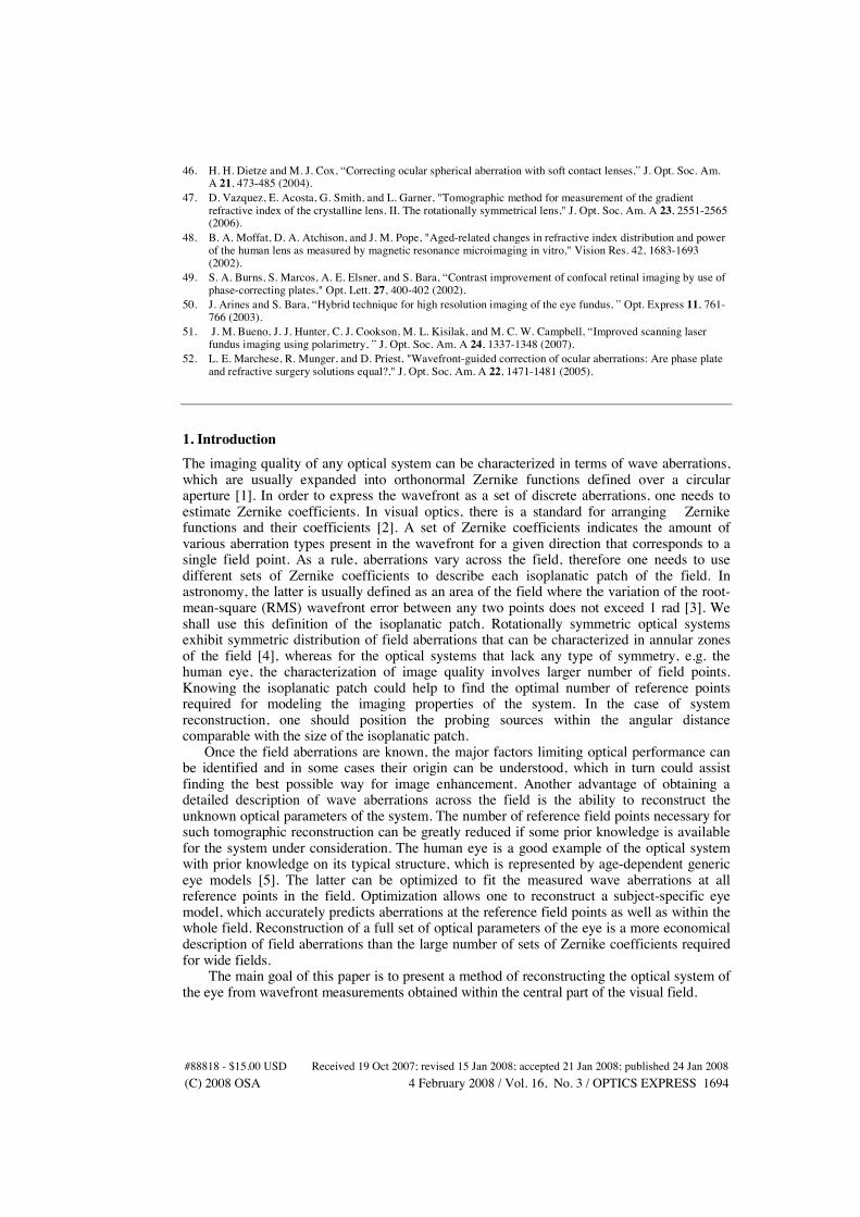
topographical map of the anterior corneal surface being an average of 18 wavefront measurement, see section 3. The low-order Zernike terms are within the range ±3 microns, which is consistent with a large study of topography of the normal cornea by Navarro et al. [31]. It would be interesting to compare the reconstructed shape of the cornea with a direct measurement using a corneal topographer. This is the topic for our future study.
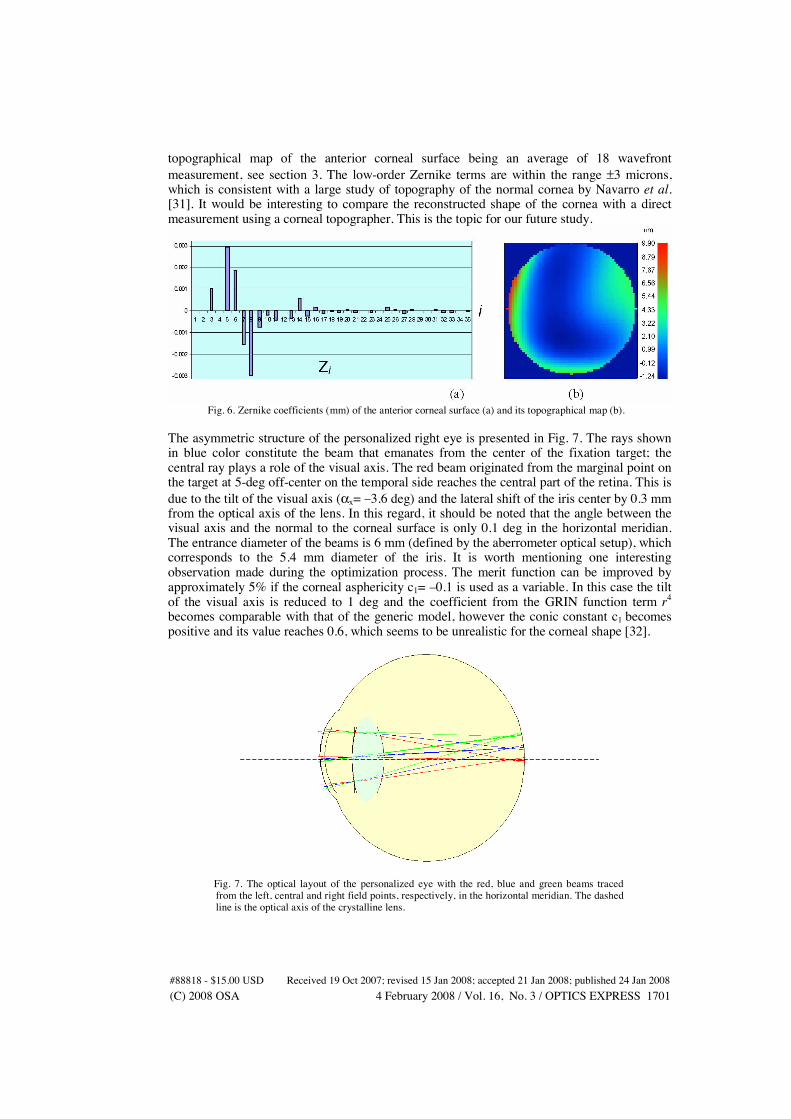
Fig. 6. Zernike coefficients (mm) of the anterior corneal surface (a) and its topographical map (b). The asymmetric structure of the personalized right eye is presented in Fig. 7. The rays shown in blue color constitute the beam that emanates from the center of the fixation target; the central ray plays a role of the visual axis. The red beam originated from the marginal point on the target at 5-deg off-center on the temporal side reaches the central part of the retina. This is due to the tilt of the visual axis (%x= #3.6 deg) and the lateral shift of the iris center by 0.3 mm from the optical axis of the lens. In this regard, it should be noted that the angle between the visual axis and the normal to the corneal surface is only 0.1 deg in the horizontal meridian. The entrance diameter of the beams is 6 mm (defined by the aberrometer optical setup), which corresponds to the 5.4 mm diameter of the iris. It is worth mentioning one interesting observation made during the optimization process. The merit function can be improved by approximately 5% if the corneal asphericity c1= #0.1 is used as a variable. In this case the tilt of the visual axis is reduced to 1 deg and the coefficient from the GRIN function term r4
becomes comparable with that of the generic model, however the conic constant c1 becomes positive and its value reaches 0.6, which seems to be unrealistic for the corneal shape [32].
Fig. 7. The optical layout of the personalized eye with the red, blue and green beams traced from the left, central and right field points, respectively, in the horizontal meridian. The dashed line is the optical axis of the crystalline lens.
#88818 - $15.00 USD Received 19 Oct 2007; revised 15 Jan 2008; accepted 21 Jan 2008; published 24 Jan 2008(C) 2008 OSA 4 February 2008 / Vol. 16, No. 3 / OPTICS EXPRESS 1701
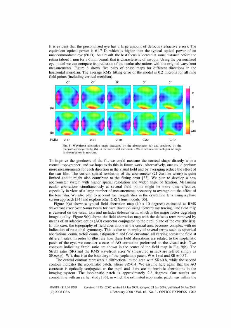
It is evident that the personalized eye has a large amount of defocus (refractive error). The equivalent optical power is 61.7 D, which is higher than the typical optical power of an unaccommodated eye (60 D). As a result, the best focus is located at some distance before the retina (about 1 mm for a 6 mm beam), that is characteristic of myopia. Using the personalized eye model we can compare its prediction of the ocular aberrations with the original wavefront measurements. Figure 8 shows five pairs of phase maps for different directions in the horizontal meridian. The average RMS fitting error of the model is 0.2 microns for all nine field points (including vertical meridian).
2 0 -2
µm
-5° -3° 0° 3° 5°
(a) (b) RMS: 0.17 0.21 0.19 0.22 0.19
Fig. 8. Wavefront aberration maps measured by the aberrometer (a) and predicted by the
reconstructed eye model (b) in the horizontal meridian. RMS difference for each pair of maps is shown below in microns.
To improve the goodness of the fit, we could measure the corneal shape directly with a corneal topographer, and we hope to do this in future work. Alternatively, one could perform more measurements for each direction in the visual field and by averaging reduce the effect of the tear film. The current spatial resolution of the aberrometer (21 Zernike terms) is quite limited and it might also contribute to the fitting error [33]. We plan to develop a new aberrometer system with higher spatial resolution and wider angle of fixation. Measuring ocular aberrations simultaneously at several field points might be more time effective, especially in view of a large number of measurements necessary to average out the effect of the tear film. We also plan to account for irregularities in the crystalline lens using a phase screen approach [34] and explore other GRIN lens models [35]. Figure 9(a) shows a typical field aberration map (10 x 10 degrees) estimated as RMS wavefront error over 6-mm beam for each direction using forward ray tracing. The field map is centered on the visual axis and includes defocus term, which is the major factor degrading image quality. Figure 9(b) shows the field aberration map with the defocus term removed by means of an adaptive optics (AO) corrector conjugated to the pupil plane of the eye (the iris). In this case, the topography of field aberrations in the central area becomes complex with no indication of rotational symmetry. This is due to interplay of several terms such as spherical aberrations, coma, trefoil coma, astigmatism and field curvature, all varying across the field at different rates. In order to illustrate how these field aberrations are related to the isoplanatic patch of the eye, we consider a case of AO correction preformed on the visual axis. Two contours indicating Strehl ratio are shown in the center of the field map in Fig. 9(b). The Strehl ratio (SR) and the RMS wavefront error W (measured in rad) are related simply as SR=exp(# W2), that is at the boundary of the isoplanatic patch, W = 1 rad and SR = 0.37. The central contour represents a diffraction-limited area with SR>0.8, while the second contour indicates the isoplanatic patch, where SR>0.4. We assume here again that the AO corrector is optically conjugated to the pupil and there are no intrinsic aberrations in the imaging system. The isoplanatic patch is approximately 2.8 degrees. Our results are comparable with an earlier study [36], in which the estimated isoplanatic patch was within the
#88818 - $15.00 USD Received 19 Oct 2007; revised 15 Jan 2008; accepted 21 Jan 2008; published 24 Jan 2008(C) 2008 OSA 4 February 2008 / Vol. 16, No. 3 / OPTICS EXPRESS 1702

range of 2-4 degrees. It is worth noting that the isoplanatic patch predicted from the personalized model is an average estimate, since the contribution of the tear film is reduced. In view of the fact that the tear film is located at some distance from the pupil, the isoplanatic patch might undergo some variations under real conditions (from blink to blink of the eye). It is our intention to investigate the optical effect of the tear film and its impact on the isoplanatic patch.
4.06 4.04 4.02 4.00 3.99 3.97 3.95 3.93 3.91 3.89 3.87
1.63 1.59 1.56 1.52 1.49 1.46 1.43 1.39 1.36 1.33 1.30
0.4
0.8
-5° 0° 5° µm -5° 0° 5° µm 5° 0° -5°
5° 0° -5° (a) (b)
Fig. 9. Aberration maps predicted by the eye model (a) and the model after defocus correction (b).
5. Conclusion We have presented a method of reconstructing the optical system of the eye from wavefront measurements by using reverse ray tracing. The optimization of a generic eye model is considered and the main strategy of balancing interrelated ocular parameters is outlined. The numerical example of reconstructing a subject-specific eye model is presented. The field aberrations predicted by the eye model are consistent with the wavefront measurements; the average RMS fitting error of the model is 0.2 microns. We expect that direct measurements of the anterior surface of the cornea obtained with a corneal topographer could potentially improve the goodness of the fit. This might also help to disentangle high-order aberrations of the cornea from those occurring in the crystalline lens. Ultimately, one could gain from personalized eye models a better insight of the aberration compensation mechanism in the human eye [37]. The ability to predict field aberrations using the reconstructed eye model is essential for wide-field compensation of ocular aberrations [38], in particular for optimizing retinal imaging systems with AO correction [39]. We have estimated the isoplanatic patch of the personalized eye model (2.8 deg) by simulating an ideal AO correction on axis. This approach can be extended to simulate realistic retinoscopic measurements [40], eccentric photorefraction images [41,42], and optical performance of other imaging techniques, including intra-ocular lenses [43,44], contact lenses [45,46]. The reconstruction of the crystalline lens and its GRIN structure provides an in vivo method to study the lens growth and age-related changes, which complements the existing in vitro methods [47,48]. complimentary might be a Personalized eye models could be of great help for improving the optical performance of various visual and imaging instruments [49-51] as well as for wavefront-guided refractive surgery [52].
Acknowledgment This research was funded by Science Foundation Ireland Grants No. 01/PI.2/B039C and 07/IN.1/I906
#88818 - $15.00 USD Received 19 Oct 2007; revised 15 Jan 2008; accepted 21 Jan 2008; published 24 Jan 2008(C) 2008 OSA 4 February 2008 / Vol. 16, No. 3 / OPTICS EXPRESS 1703