reconfigurable h-shaped antenna iet 2011bura.brunel.ac.uk/bitstream/2438/6332/2/fulltext.pdfthe...
TRANSCRIPT
Wireless Networks and Communications Centre(WNCC), Brunel University, UK
1
ABSTRACT
This paper presents an H-shaped reconfigurable antenna fed by a coplanar waveguide (CPW) for wireless
applications. The antenna consists of an H-shape radiator and a CPW printed on a PCB and a varactor
diode connecting the upper and lower arms of the H-shape radiator for reconfigurability. The uniqueness of
the antenna lies on the ability to select the operating mode and frequencies electronically using a varactor
diode. By selecting the DC bias voltages of 11.5, 10 and 8 V across the varactor diode, which in turn
selecting the corresponding varactor capacitances of 2, 4 and 6 pF, the antenna can be controlled to operate
in three different modes, namely, a single-band mode to cover the Global System for Mobile
communications 1900 (GSM1900) system, a dual-band mode at 1.88 and 2.4 GHz to cover the GSM1900
and Bluetooth or Wireless Local Area Network (WLAN) systems, respectively, and a tri-band mode at
1.57, 1.88 and 2.4 GHz to cover the GSM1900, WLAN and Global Position System (GPS), respectively.
Furthermore, by varying the varactor capacitance from 7 to 13 pF, the GPS and WLAN bands can be tuned
by 11.44 % (1.57 - 1.4 GHz) and 6.46 % (2.4 - 2.25 GHz), respectively, yet keeping the 1.88-GHz band
unchanged. Thus our proposed single antenna can be used to support different wireless standards. Detailed
studies on the reflection coefficient, current density, antenna pattern and gain are carried out using
simulations and measurements to investigate the behaviour of the antenna at each resonant frequency in
each operating mode.
Index Terms— Reconfigurable Antenna, Multiband Antenna, H-Shaped antenna, Tunable Antenna, CPW
feed, Frequency selectivity
Reconfigurable Tri-Band H-Shaped Antenna with Frequency Selectivity
Feature for Compact Wireless Communication Systems
Hattan F. AbuTarboush, R. Nilavalan, K. M. Nasr, S. W. Cheung, T. Peter, H. S. Al-Raweshidy and D. Budimir

Wireless Networks and Communications Centre(WNCC), Brunel University, UK
2
I. I INTRODUCTION
Several studies on multiband-antenna designs for different wireless applications using H-shape [1]-[4] and
T-shape antennas [5]-[8] have been reported. Although multiband antennas can be used in different
wireless systems, they lack the flexibility to accommodate new services when compared with
reconfigurable antennas which can be considered as one of the key advances for future wireless
communication transceivers. In the past few years, there has been a significant interest in the field of
reconfigurable-multiband antennas. Different techniques used for reconfigurable antennas were reported in
[9]. One of the advantages of reconfigurable antenna is to use the same antenna for multiband operation,
thus the total antenna volume can be reduced when compared with those of having fixed multibands,
leading to a reduction in the overall volume of wireless device and more space for integrating with other
electronic components.
Reconfigurable antennas can be classified into three different categories, namely, frequency-reconfigurable
pattern-reconfigurable and polarization-reconfigurable antennas. In frequency-reconfigurable antenna, the
frequency of the operation band can be tuned/switched to different frequencies, so the antenna is smaller
than fixed multiband antenna but has multiple functions for different applications. In [10] and [11], PIN
diode switches were used for tuning/switching the operation frequencies of the antennas. In [12], switching
among different feeding locations of the antenna was proposed to reconfigure the operating frequencies for
multiband wireless applications. In [13], a method for reconfigurable patch antennas was studied for
satellite and terrestrial applications. In these frequency-reconfigurable antennas, the shapes of the radiation
patterns remained relatively constant when the frequencies were switched, which is one of the important
criteria in the design of frequency-reconfigurable antennas. In pattern-reconfigurable antenna, the radiation
pattern can be tuned/switched based on system requirements, without changing the operation frequency
band. The main antenna beam can be steered to different directions. This type of pattern reconfigurability
was studied in [14] by using a coplanar waveguide (CPW)-fed antenna. In [15], a reconfigurable antenna
combining both frequency and radiation pattern reconfigurabilities was introduced. In polarization-

Wireless Networks and Communications Centre(WNCC), Brunel University, UK
3
reconfigurable antenna, the polarization can be switched from linear to circular [16] and from left-hand-
circular polarization (LHCP) to right-hand-circular polarization (RHCP) [17]. A novel reconfigurable-patch
antenna with both frequency and polarization diversities was studied in [18].
An independent-multiband antenna, fed by a CPW with finite lateral strips, for WLAN applications was
studied in [19], which showed that the 2.4- and 5.2-GHz bands could be controlled by changing the
physical dimensions of the antenna in terms of the length and the width of the lateral strips. A different
approach to design an independent-multiband Planer Inverted-F Antenna (PIFA) was studied in [20], where
three resonant frequencies were generated and controlled by employing additional parts in the main
radiating patch. Three resonant frequencies were generated to cover the GSM, DCS and DMB applications.
However, this design resulted in larger dimensions, higher profile and a complicated structure to
manufacture. Another design was also reported recently to design a multiband independent antenna by
cutting slots within the main radiated patch to introduce multiband operation [21]. The Double-T antenna
(or H-shape antenna) reported in [7] can operate only in a dual-band mode at the higher frequencies of 2.4
and 5.2 GHz. Multiband antennas can cover multiple frequencies using a single antenna and so are very
desirable for wireless applications. However, fixed multiband antenna usually requires complicated filters
with inflexible requirements to improve their out-of-band noise rejection. The filters are bulky and can add
complexity to the communication systems [9]. As a solution to these problems, reconfigurable antenna can
achieve a better out-of-band noise rejection especially when the design has only one switch with low
voltage for control, as in the proposed design. Furthermore, planar antennas, due to its low profile, low
fabrication cost and simple feeding structure is more attractive for reconfigurability purposes.
Switchable designs using three or more switches were proposed in [10, 24 and 25]. These techniques had
limitations in terms of the number of switches required to reconfigure the antenna to a single-band or dual-
band modes. In addition to increased complexity and space requirements, the multitude of switches also
increases the power consumption and fabrication cost. The antenna proposed in this paper employs a

Wireless Networks and Communications Centre(WNCC), Brunel University, UK
4
simple varactor diode to select three operational modes, i.e., the single-band, dual-band and tri-band
modes, yet without requiring to incorporate with any additional parts to the antenna, yet having more
flexibility with smaller size.
The proposed technique was first introduced in [22] and detailed analyses with further new results are
presented in this paper. The proposed antenna has an H-shaped radiator, a CPW and a varactor diode
connecting the upper and lower arms of the H-shape radiator. Through the use of DC bias voltage across
the varactor diode, the antenna can be operated in three different modes, a single-band mode covering the
Global System for Mobile communications 1900 (GSM1900) system, a dual-ban
d mode at 1.88 and 2.4 GHz to cover GSM1900 and Bluetooth or Wireless Local Area Network (WLAN)
systems, respectively, and a tri-band mode at 1.57, 1.88 and 2.4 GHz to cover the GSM1900, WLAN and
Global Position System (GPS), respectively. The GPS system uses circular polarization and the antenna
presented in this paper has linear polarization. However, linearly polarized antennas can also be useful for
GPS system in many practical multipath scenarios. According to the investigations carried out in [23] a
linearly polarized PIFA antenna can reach relatively high performance, comparable with that of right hand
circularly polarized antennas.
The frequency bands in the three modes of operation can also be controlled by the varactor diode and the
widths of the arms in the H-shape radiator. Detailed simulation studies on the reflection coefficient, current
density, antenna pattern and gain are carried out to investigate the behaviour of the antenna at each
resonant frequency. Results are validated by measurements using the Small Antenna Radiated Testing
Range (SMART) at the National Physical Laboratory (NPL).
The paper is organized as follows. Section II describes the antenna configuration. The simulation and
measurement results for the single-, dual- and tri-frequency bands are presented in Section III. Studies on
the H-shape radiator of antenna are given in Section IV. Finally Section VI concludes the paper.

Wireless Networks and Communications Centre(WNCC), Brunel University, UK
5
II. ANTENNA CONFIGURATION
The structure of the proposed reconfigurable antenna is shown in Fig. 1, which is optimised using the
HFSS software version 11.2 with the main optimized dimensions listed in Table I. The antenna has an
overall area of 43.6 mm x 50 mm, suitable for compact wireless devices. The antenna consists of an H-
shape radiator, a CPW feed line and a varactor diode connecting the two horizontal arms of the H-shape
radiator as shown in Fig. 1. The antenna is designed on an FR-4 substrate with a thickness of 1.57 mm and
a dielectric constant of 4.4. The CPW has a characteristic impedance of 50 Ω. The varactor diode used in
our design is BB184 from NXP. From its data sheet, the varactor diode has a capacitance C ranging from
14 to 1 pF, depending on the DC bias voltage, as shown in Fig. 2, an inductance of 0.6 nH, a resistance of
0.65 Ω and physical dimension of 0.6 mm x 0.9 mm. The location of the varactor diode on the antenna is
optimized to provide the desirable frequency bands for the antenna.
Fig. 1 Layout of proposed antenna
Table I: DIMENSIONS OF PROPOSED ANTENNA (UNITS IN mm)
W W1 W2 W3 W4 3 20 20 10.6 5
W5 W6 WT L L1 4 4 43.6 30.6 19.5 L2 L3 L4 L5 L6

Wireless Networks and Communications Centre(WNCC), Brunel University, UK
6
26.5 15 14 2.5 40 LT h G1 G2 50 1.57 0.5 0.5
III. SIMULATIONS AND MEASUREMENTS RESULTS
The performances of the proposed antenna, in terms of return losses, radiation patterns and gains, with
different DC bias voltages across the varactor diode, have been studied using computer simulation. In the
simulation tests, the varactor diode is modelled as a capacitance using the characteristic of Fig. 2. The
proposed antenna has also been fabricated as shown in Fig. 3(a) and measured using the Small Antenna
Radiated Testing Range (SMART) at the National Physical Laboratory (NPL) shown in Fig. 3(b).
Fig. 2 Capacitance versus DC bias voltage for varactor BB184 (obtained from BB184 data sheet)
(a) (b)
Wireless Networks and Communications Centre(WNCC), Brunel University, UK
7
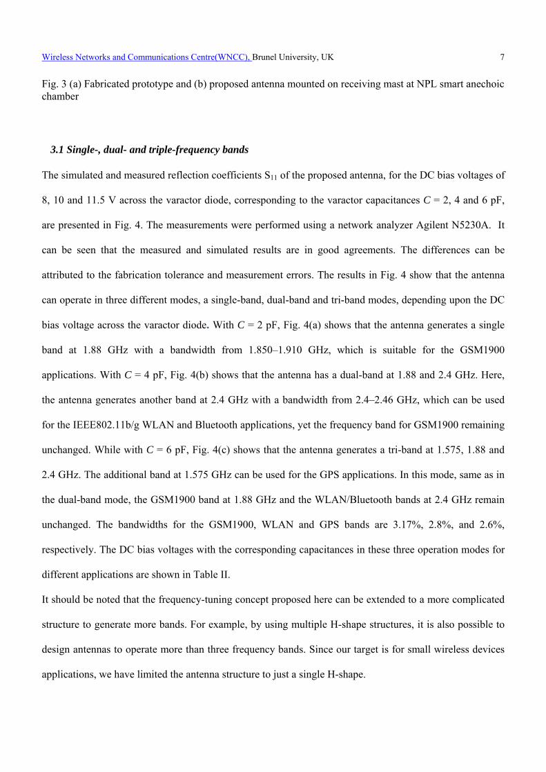
Fig. 3 (a) Fabricated prototype and (b) proposed antenna mounted on receiving mast at NPL smart anechoic chamber
3.1 Single-, dual- and triple-frequency bands The simulated and measured reflection coefficients S11 of the proposed antenna, for the DC bias voltages of
8, 10 and 11.5 V across the varactor diode, corresponding to the varactor capacitances C = 2, 4 and 6 pF,
are presented in Fig. 4. The measurements were performed using a network analyzer Agilent N5230A. It
can be seen that the measured and simulated results are in good agreements. The differences can be
attributed to the fabrication tolerance and measurement errors. The results in Fig. 4 show that the antenna
can operate in three different modes, a single-band, dual-band and tri-band modes, depending upon the DC
bias voltage across the varactor diode. With C = 2 pF, Fig. 4(a) shows that the antenna generates a single
band at 1.88 GHz with a bandwidth from 1.850–1.910 GHz, which is suitable for the GSM1900
applications. With C = 4 pF, Fig. 4(b) shows that the antenna has a dual-band at 1.88 and 2.4 GHz. Here,
the antenna generates another band at 2.4 GHz with a bandwidth from 2.4–2.46 GHz, which can be used
for the IEEE802.11b/g WLAN and Bluetooth applications, yet the frequency band for GSM1900 remaining
unchanged. While with C = 6 pF, Fig. 4(c) shows that the antenna generates a tri-band at 1.575, 1.88 and
2.4 GHz. The additional band at 1.575 GHz can be used for the GPS applications. In this mode, same as in
the dual-band mode, the GSM1900 band at 1.88 GHz and the WLAN/Bluetooth bands at 2.4 GHz remain
unchanged. The bandwidths for the GSM1900, WLAN and GPS bands are 3.17%, 2.8%, and 2.6%,
respectively. The DC bias voltages with the corresponding capacitances in these three operation modes for
different applications are shown in Table II.
It should be noted that the frequency-tuning concept proposed here can be extended to a more complicated
structure to generate more bands. For example, by using multiple H-shape structures, it is also possible to
design antennas to operate more than three frequency bands. Since our target is for small wireless devices
applications, we have limited the antenna structure to just a single H-shape.

Wireless Networks and Communications Centre(WNCC), Brunel University, UK
8
(a) (b) (c) Fig. 4 Simulated and measured return losses for (a) single band with C = 2 pF, (b) dual band with C = 4 pF and (c) tri-band with C= 6 pF.
Table II DC BIAS VOLTAGES WITH CORRESPONDING CAPACITANCES IN THREE OPERATION MODES FOR
DIFFERENT APPLICATIONS
Bias voltage C Frequency
Mode Frequency bands
Application
11.5 V 2 pF Single-band 1.88 GHz GSM1900
10 V 4 pF Dual-band 1.88 & 2.4 GHz GSM1900 & WLAN/Bluetooth
8 V 6 pF Tri-band 1.57, 1.88 & 2.4
GHzGPS, GSM1900 & WLAN/Bluetooth
3.2 Radiation Patterns, Gains and Efficiencies The simulated and measured co- and cross-polarization radiation patterns in the E- and H- planes for the
single-band, dual-band and tri-band modes are shown in Figs. 5(a)-5(c), respectively. The measured
radiation patterns have been normalized to the maximum values. It can be seen good agreements between
measured and simulated patterns. The differences in some cases are due to the fabrication tolerance,
measurements accuracy and the effects of the coaxial cable used for measurements. Figure 5 shows that the
radiation patterns at a given bias condition remain nearly constant. The cross polarization is below -15 dB
in most of the cases. More studies have also shown that the length of the CPW feed line affects the cross
polarization level. Figure 6 shows the radiation patterns in the H-plane at 2.4 GHz with different lengths
used for the CPW-feed line. It can be seen that a shorter feed line leads to a lower cross polarization. The
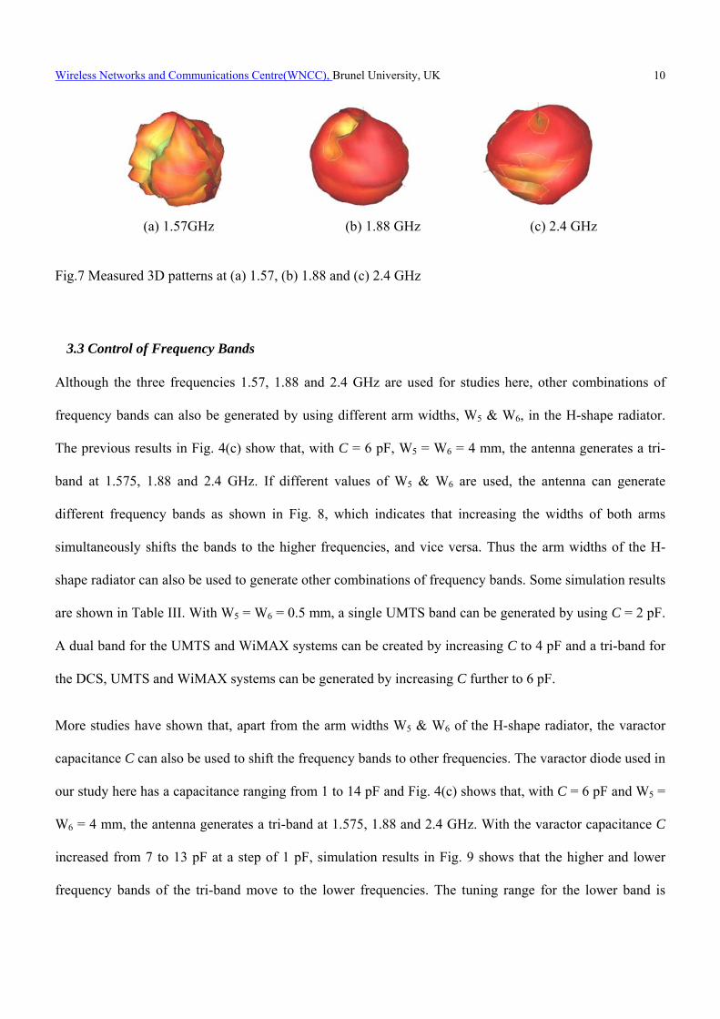
measured 3D patterns in the three bands with C = 6 pF are shown in Fig. 7. The measured peak gains at the

Wireless Networks and Communications Centre(WNCC), Brunel University, UK
9
frequencies 1.57, 1.88 and 2.4 GHz are 1.8, 3.4 and 2.5 dBi, respectively, with the corresponding simulated
radiation efficiencies of 72, 81and 75 %. Simulations have also shown that these results do not change
much in the other cases.
(a)
(b)
(c) Fig.5 Simulated and measured Co- and X-pol radiation patterns in E- and H-plane for (a) single-band, (b) dual-band and (c) Tri-band modes.
Fig. 6 Effect of feed-line length on radiation patterns in H-plane at 2.4 GHz with C = 6 pF.
Wireless Networks and Communications Centre(WNCC), Brunel University, UK
10
(a) 1.57GHz (b) 1.88 GHz (c) 2.4 GHz Fig.7 Measured 3D patterns at (a) 1.57, (b) 1.88 and (c) 2.4 GHz
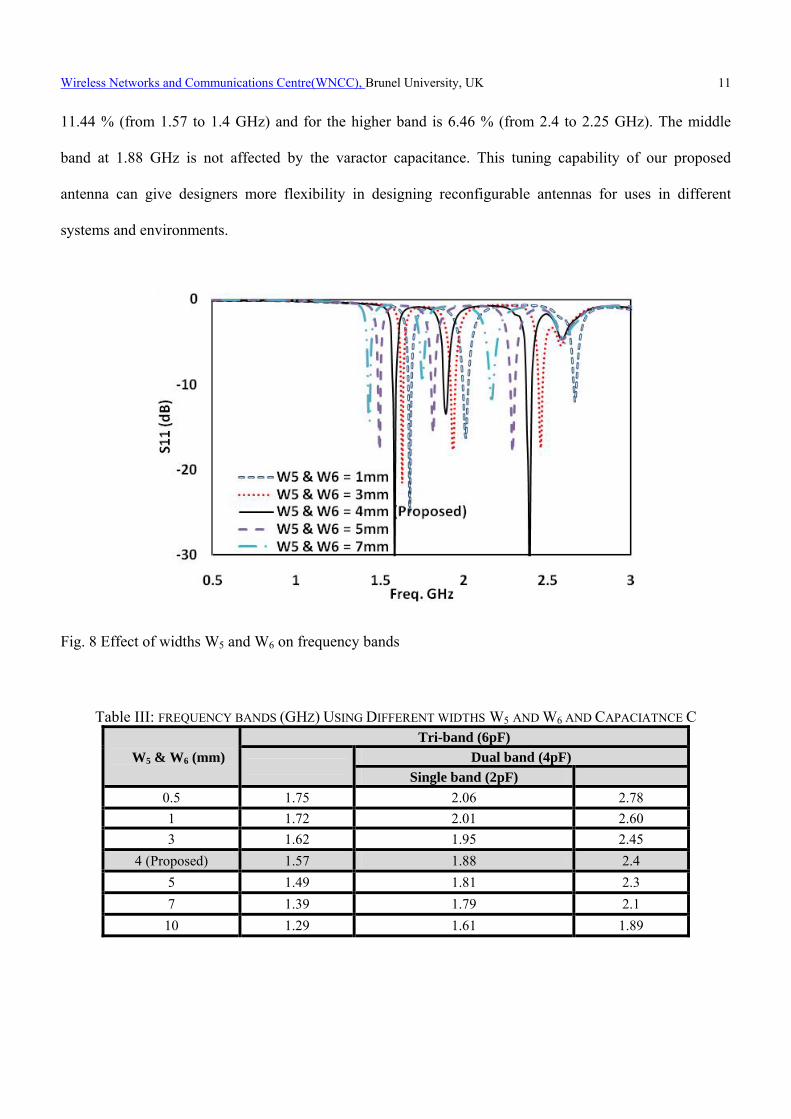
3.3 Control of Frequency Bands Although the three frequencies 1.57, 1.88 and 2.4 GHz are used for studies here, other combinations of
frequency bands can also be generated by using different arm widths, W5 & W6, in the H-shape radiator.
The previous results in Fig. 4(c) show that, with C = 6 pF, W5 = W6 = 4 mm, the antenna generates a tri-
band at 1.575, 1.88 and 2.4 GHz. If different values of W5 & W6 are used, the antenna can generate
different frequency bands as shown in Fig. 8, which indicates that increasing the widths of both arms
simultaneously shifts the bands to the higher frequencies, and vice versa. Thus the arm widths of the H-
shape radiator can also be used to generate other combinations of frequency bands. Some simulation results
are shown in Table III. With W5 = W6 = 0.5 mm, a single UMTS band can be generated by using C = 2 pF.
A dual band for the UMTS and WiMAX systems can be created by increasing C to 4 pF and a tri-band for
the DCS, UMTS and WiMAX systems can be generated by increasing C further to 6 pF.
More studies have shown that, apart from the arm widths W5 & W6 of the H-shape radiator, the varactor
capacitance C can also be used to shift the frequency bands to other frequencies. The varactor diode used in
our study here has a capacitance ranging from 1 to 14 pF and Fig. 4(c) shows that, with C = 6 pF and W5 =
W6 = 4 mm, the antenna generates a tri-band at 1.575, 1.88 and 2.4 GHz. With the varactor capacitance C
increased from 7 to 13 pF at a step of 1 pF, simulation results in Fig. 9 shows that the higher and lower
frequency bands of the tri-band move to the lower frequencies. The tuning range for the lower band is
Wireless Networks and Communications Centre(WNCC), Brunel University, UK
11
11.44 % (from 1.57 to 1.4 GHz) and for the higher band is 6.46 % (from 2.4 to 2.25 GHz). The middle
band at 1.88 GHz is not affected by the varactor capacitance. This tuning capability of our proposed
antenna can give designers more flexibility in designing reconfigurable antennas for uses in different
systems and environments.
Fig. 8 Effect of widths W5 and W6 on frequency bands
Table III: FREQUENCY BANDS (GHZ) USING DIFFERENT WIDTHS W5 AND W6 AND CAPACIATNCE C
W5 & W6 (mm)
Tri-band (6pF)
Dual band (4pF)
Single band (2pF)
0.5 1.75 2.06 2.78
1 1.72 2.01 2.60
3 1.62 1.95 2.45
4 (Proposed) 1.57 1.88 2.4
5 1.49 1.81 2.3
7 1.39 1.79 2.1
10 1.29 1.61 1.89

Wireless Networks and Communications Centre(WNCC), Brunel University, UK
12
IV. STUDIES ON H-SHAPE RADIATOR 4.1 Full H-shape radiator
The previous results show that a single-band, dual-band or tri-band mode can be generated by using the
varactor diode through the applied DC bias voltage. Here we study the operating modes using the Smith
chart. Figure 10 shows the Smith charts with the varactor capacitance C = 2, 4 and 6 pF. With C = 2 pF,
Fig. 10(a) shows that S11 is less than -10 dB for the frequency band from 1.86 to 1.91 GHz and minimum at
1.88 GHz, generating the single-band mode. With C increased to 4 pF, Fig. 10(b) shows that the 1.88-GHz
band remains unchanged, but a higher frequency band is created from 2.37 to 2.44 GHz with S11 < -10 dB
and minimum at 2.4 GHz. This generates the dual-band mode. With C further increased to 6 pF, Fig. 10(c)
shows that the 1.88-GHz and 2.4-GHz bands remain about the same, but a lower band at 1.57 GHz is
created, resulting in a tri-band mode.
To further understand the antenna behaviour, the current distribution for the three resonant frequencies at
1.88, 2.4 and 1.57 GHz have been studied by simulation and results are shown in Figs. 11(a), 11(b) and
11(c), respectively. The current density in Fig. 11(a) shows that the CPW feed line and the H-shape
radiator have the highest densities and so generate the resonant bands at 1.88 GHz as shown in Fig. 4(a).
Figure 11 (b) shows that the highest current density is on the left-hand side (LHS) of the H-shape, which
generates the 2.4-GHZ band in Fig. 4(b), while Fig. 11(c) shows that the current concentrates most in the
right-hand side (RHS) of the H-shape radiator, generating the 1.57-GHz band in Fig. 4(c). So different
parts of the H-shape radiator are responsible for generating different frequency bands and are further
studied in the following section.

Wireless Networks and Communications Centre(WNCC), Brunel University, UK
13
Fig. 9 Effect of varactor capacitance on frequency bands
(a) (b) (c) Fig. 10 Simulated Smith Charts with varactor capacitance C of (a) 2 pF, (b) 4 pF and (c) 6 pF

Wireless Networks and Communications Centre(WNCC), Brunel University, UK
14
(a) (b) (c)
Fig. 11 Simulated current distributions at (a) 1.88 GHz, (b) 2.4 GHz and (c) 1.57 GHz with C = 6 pF 4.2 Partial H-shape radiator With the uses of only the upper arm, only the LHS of the H-shape radiator and only the RHS of the H-
shape radiator, the simulated S11 are shown in Figs. 12 (a)-(c), respectively. Figure 12(a) shows that, a
1.88-GHz band with a return loss of less than 10 dB (S11 > -10 dB) can be generated by the upper arm of
the H-shape. The lower arm with C = 2 pF increases the return loss to more than 10 dB. The 2.4-GHz band
as shown in Fig. 12(b) is mainly generated by the LHS of the H-shape with C = 4 or 6 pF, while the 1.57-
GHz band is generated by the RHS of the H-shape with C = 6 pF as shown in Fig. 12(c).
The resonant behaviours of the antenna in these three conditions are also studied using the Smith charts in
Fig. 13. With the use of only the upper arm in the H-shape, Fig. 13(a) shows that the return loss cannot be
larger than 10 dB (i.e., cannot reach inside the -10-dB circle). With C = 2, 4, or 6 pF, the antenna with only
the LHS of the H-shape generates a frequency band centred at 2.4 GHz as can be seen in Fig. 13(b), while
the antenna with only the RHS of the H-shape generate the bands all centred at 1.88 GHz as shown in Fig.
13(c). These results agree well with the corresponding results in Figs. 12(a), 12(b) and 12(c). Figures 12
and 13 indicate that different parts of the H-shape are used to generated different frequency bands.
However, it should be noted that the role of the varactor diode is simply to help achieve the required
matching at these frequencies.

Wireless Networks and Communications Centre(WNCC), Brunel University, UK
15
(a) (b) (c) Fig. 12 Simulated S11 with (a) upper arm only and two arms with C = 2 pF, (b) LHS arms and C = 2, 4, and 6 pF and (c) RHS arms with C = 2, 4 and 6 pF.
(a) (b) (c)
Fig. 13 Simulated Smith chart with (a) top arm only and two arms with C = 2 pF, (b) LHS arms and C = 2, 4, and 6 pF and (c) RHS arms with C = 2, 4 and 6 pF.
V. CONCLUSIONS The paper has presented a reconfigurable H-shaped antenna using a varactor to control three different
operation modes, namely, a single-band mode to cover the GSM1900 system, a dual-band mode at 1.88 and
2.4 GHz to cover the GSM1900 and Bluetooth or WLAN systems, respectively, and a tri-band mode at
1.57, 1.88 and 2.4 GHz to cover the GSM1900, WLAN and GPS system, respectively. Simulation studies
and measurements on the reflection coefficient, current density, antenna pattern and gain have been carried
out to study the antenna behaviour. Results have shown that, by using the DC bias voltage across the
varactor diode, which in turn controls the diode capacitance, the frequency bands in different operation
modes can be turned for other applications. The proposed antenna is small and light weight, and so suitable
for small wireless devices.
ACKNOWLEDGMENTS
The measurements at the NPL SMART chamber were supported by the Measurements for Innovators
(MFI) program and the National Measurement Office, an Executive Agency of the Department for
Business, Innovation and Skills.

Wireless Networks and Communications Centre(WNCC), Brunel University, UK
16
REFERENCES [1] D. Singh, C. Kalialakis, P. Gardner, and P. S. Hall, “Small H-shaped antennas for MMIC
applications,” IEEE Transactions on Antennas and Propagation., vol. 48, pp. 1134–1141, July 2000.
[2] A.F. Sheta, “A novel H-shaped patch antenna”, Microwave Optical Technology Letter P.62–65, 2001.
[3] S.C. Gao, L.W. Li, M.S. Leong and T.S. Yeo, "Wide-band microstrip antenna with an H-shaped
coupling aperture", IEEE Transactions on Vehicular Technology, vol. 51, pp. 17-27, 2002.
[4] T.Y. Yum, "A novel H-shaped active integrated antenna," Antennas and Propagation Society
International Symposium, 2003. IEEE, vol. 2, pp. 708-711 vol.2, 2003.
[5] R. B. Hwang, "A broadband CPW-fed T-shaped antenna for wireless communications," Microwaves,
Antennas and Propagation, IET Proceedings -, vol. 151, pp. 537-543, 2004.
[6] S.B. Chen, Y.C. Jiao, W.W. and F.S. Zhang, "Modified T-shaped planar monopole antennas for
multiband operation," IEEE Transactions on Microwave Theory and Techniques, vol. 54, pp. 3267-
3270, 2006.
[7] Y.L. Kuo and K.L. Wong, "Printed double-T monopole antenna for 2.4/5.2 GHz dual-band WLAN
operations," IEEE Transactions on Antennas and Propagation, vol. 51, pp. 2187-2192, 2003.
[8] M. Sanad, “Double C-Patch Antennas Having Different Aperture Shapes,” IEEE Proceedings on
Antennas and Propagation, pp.2116-2119, June 1995
[9] S. Yang, C. Zhang, H. Pan, A. Fathy and V. Nair, "Frequency-reconfigurable antennas for multiradio
wireless platforms," IEEE Microwave Magazine, vol. 10, pp. 66-83, 2009.
[10] A. Sheta and S. F. Mahmoud, "A Widely Tunable Compact Patch Antenna," IEEE Antennas and
Wireless Propagation Letters, vol. 7, pp.40-42, 2008.
[11] H. F. AbuTarboush, R. Nilavalan, S. W. Cheung, K. Nasr, T. Peter, and D. Budimir “A
Reconfigurable Wideband and Multiband Antenna Using Dual-Patch Elements for Compact Wireless
Devices," IEEE Transaction on Antennas and Propagation, 2011. (Accepted).
[12] A. C. K. Mak, C. R. Rowell, R. D. Murch and C.L. Mak, "Reconfigurable Multiband Antenna
Designs for Wireless Communication Devices," IEEE Transactions on Antennas and Propagation,
vol. 55, pp. 1919-1928, 2007.
[13] M. Ali, A. T. M. Sayem and V. K. Kunda, "A Reconfigurable Stacked Microstrip Patch Antenna for
Satellite and Terrestrial Links," IEEE Transactions on Vehicular Technology, vol. 56, pp. 426-435,
2007.
[14] W. S. Kang, J. A. Park and Y. J. Yoon, "Simple reconfigurable antenna with radiation pattern,"
Electronics Letters, vol. 44; 44, pp. 182-183, 2008.
Wireless Networks and Communications Centre(WNCC), Brunel University, UK
17
[15] M. Lai, T. Wu, J. Hsieh, C. Wang and S. Jeng, "Design of reconfigurable antennas based on an L-
shaped slot and PIN diodes for compact wireless devices," IET Microwaves, Antennas &
Propagation, vol. 3, pp. 47-54, 2009.
[16] R. Chen and J. Row, "Single-Fed Microstrip Patch Antenna With Switchable Polarization," IEEE
Transactions on Antennas and Propagation, vol. 56, pp. 922-926, 2008.
[17] B. Kim, B. Pan, S. Nikolaou, Y. Kim, J. Papapolymerou and M. Tentzeris, "A Novel Single-Feed
Circular Microstrip Antenna With Reconfigurable Polarization Capability," IEEE Transactions on
Antennas and Propagation, vol. 56, pp. 630-638, 2008.
[18] N. Jin, F. Yang and Rahmat-Samii, "A novel patch antenna with switchable slot (PASS): dual-
frequency operation with reversed circular polarizations," IEEE Transactions on Antennas and
Propagation, vol. 54, pp. 1031-1034, 2006.
[19] R. K. Raj, M. Joseph, C. K. Aanandan, K. Vasudevan and P. Mohanan, "A New Compact Microstrip-
Fed Dual-Band Coplanar Antenna for WLAN Applications,” IEEE Transactions on Antennas and
Propagation, vol. 54, pp. 3755-3762, 2006.
[20] D. Kim, J. Lee, C. Sik Cho and T. K. Lee, "Design of a Compact Tri-Band PIFA Based on
Independent Control of the Resonant Frequencies," IEEE Transactions on Antennas and Propagation,
vol. 56, pp. 1428-1436, 2008.
[21] Hattan F. AbuTarboush, R. Nilavalan, T. Peter and S. W. Cheung, “Multiband Inverted-F Antenna
with Independent Bands for Small and Slim Cellular Mobile Handsets," IEEE Transaction on
Antennas and Propagation, Vol. 59, No.7, 2011.
[22] Hattan F. AbuTarboush, R. Nilavalan, K. Nasr, H. Al-Raweshidy, D. Budimir, "A reconfigurable H-
shape antenna for wireless applications," Proceedings of the Fourth European Conference on
Antennas and Propagation (EuCAP 2010), pp.1-4, 12-16 April 2010.
[23] A. A. Serra, P. Nepa, G. Manara, R. Massini, "A Low-Profile Linearly Polarized 3D PIFA for
Handheld GPS Terminals," IEEE Transactions on Antennas and Propagation, vol.58, no.4, pp.1060-
1066, 2010.
[24] C. W Jung, M.-J. Lee and F. De Flaviis, "Reconfigurable dual-band antenna with high frequency ratio
(1.6:1) using MEMS switches," Electronics Letters, vol.44, no.2, pp.76-77, January 2008.
[25] T.-Y. Han and C.-T. Huang, "Reconfigurable monopolar patch antenna," Electronics Letters, vol.46,
no.3, pp.199-200, Feb. 4 2010.