recommended schedule - ibiblio · recommended schedule (8:00 am to 8:30 am) – introduction and...
TRANSCRIPT

INST 180 (1-day Control Valves course)
Recommended schedule
(8:00 AM to 8:30 AM) – Introduction and Quiz
(8:30 AM to 9:30 AM) – Control valve construction and types – Questions 1 through 5
(9:30 AM to 9:45 AM) – Break
(9:45 AM to 10:30 AM) – Pneumatic control devices – Questions 6 through 9
(10:30 AM to 11:00 AM) – Lab activity – I/P transducer and 3-15 PSI control valve actuator
(11:00 AM to 12:00 PM) – Lunch
(12:00 PM to 1:00 PM) – Valve positioners – Questions 10 through 13
(1:00 PM to 1:30 PM) – Lab activity – Positioner demonstration
(1:30 PM to 1:45 PM) – Break
(1:45 PM to 2:15 PM) – Motor-operated valves (MOVs) – Questions 14 through 17
(2:15 PM to 3:00 PM) – Cavitation and valve stiction – Questions 20 through 23
(3:00 PM to 3:30 PM) – Video: cavitation at Glen Canyon dam – Questions 20 through 22
Video time index ContentStart to 1:50 Intro and shots of MOV actuators in use4:43 to 12:36 Cavitation damage in spillway15:38 to 17:56 Adding air slots in spillway24:20 to 25:18 Testing the new spillway
(3:30 PM to 3:45 PM) – Break
(3:45 PM to 4:30 PM) – Quiz and Review
1

Questions
Question 1
Identify these different valve types from their respective diagrams:
Valve #1:
Inlet Outlet
Valve #2:
Inlet
Outlet
2

Valve #3:
InletOutlet
Valve #4:
Inlet Outlet
3

Valve #5:
Inlet Outlet
Valve #6:
Inlet Outlet
file i00770
4

Question 2
Suppose we had a single-ported globe valve such as this controlling fluid flow, with inlet and outletpressures as shown in the illustration. If the plug has a cross-sectional area of 3 square inches, how muchforce will be exerted on the plug by the fluid? In which direction will this force be exerted?
Inlet
Outlet320 PSI 270 PSI
5

Now suppose we replace the single-ported globe valve with a double-ported globe valve of similaroperating characteristics. Given the same inlet and outlet pressures, how much (net) force will be exertedon the plugs by the fluid? Assume the upper plug has a cross-sectional area of 3 square inches, and the lowerplug a cross-sectional area of 2 square inches:
InletOutlet320 PSI 270 PSI
Which of these two control valves will be easier to position (i.e. require less actuating force), all otherfactors being equal?
Suggestions for Socratic discussion
• For the valve requiring less actuating force, are there any disadvantages to the design? Clearly, loweractuating force is a good thing, so there must be some drawback to this design or else all control valveswould be manufactured this way!
• Is the direction of flow arbitrary for this control valve, or is there a reason why the flow should bepassing up past the plug rather than down past it?
• Does the packing of a double-ported control valve need to be different than the packing of a single-portedvalve? Why or why not?
file i00772
6

Question 3
One of the major processes used to treat municipal wastewater is aeration, where the dissolved oxygenconcentration of the wastewater is increased by bubbling air through the water in an aeration basin. Adissolved oxygen (“DO”) analyzer measures the oxygen concentration in the wastewater, and a controllervaries the speeds of blowers pumping air into the basins using AC motors powered through variable-frequencydrives (VFDs) which allow the controllers’ 4-20 mA output signals command the motors how fast to spin:
Aeration basinSilencerSilencer
Blower
Distribution nozzles
VFD VFD
ATDO
AIC
EffluentInfluent
FICFIC
FTFT
25 25
18 19
18 19
FY FY
18 19
< <
Identify the proper actions for each controller in this system, assuming direct-acting transmitters andVFDs that spin the motor at a faster speed with a greater 4-20 mA signal:
AIC-25 = direct or reverse? FIC-18 = direct or reverse? FIC-19 = direct or reverse?
Suppose an operator calls you to examine this system and determine why the dissolved oxygen valueis not holding at setpoint. According to the operator, everything was working fine yesterday, and had beenworking fine for months. You go to the control room to view the display on the DCS, and you find thesevalues:
Parameter AIC-25 FIC-18 FIC-19PV 41% 99% 2%SP 75% 100% 100%
Output 100% 82% 100%
Identify two different faults, each one independently capable of accounting for all symptoms evident inthis table.
•
•
file i00776
7

Question 4
Read selected portions of the “Fisher Type 1098-EGR and 1098H-EGR Pilot-Operated Regulators”product bulletin (document 71.2:1098-EGR), and answer the following questions:
Page 4 shows excellent illustrations of the regulator body and actuator assemblies, as well as internalviews of the pilot mechanism. Identify the type of valve trim used to throttle process fluid (stem-guided,cage-guided, port-guided), and also whether the valve body is direct or reverse acting. Additionally, explainhow the valve plug position may be monitored while the regulator is in service.
The purpose of the pilot is to provide a loading pressure to the actuator of the 1098 pressure regulator.Page 6 explains how the pilot provides this loading pressure to the main actuator. Explain what this “loadingpressure” does to the main regulator mechanism, and also how the regulator self-adjusts to changes in thedownstream pipe pressure. Also, identify the fluid used to actuate the regulator – it is not instrument air!
What type of stem packing do you see used in this valve? Explain why you think the valve is designedin this way.
Suggestions for Socratic discussion
• A powerful problem-solving technique is performing a thought experiment where you mentally simulatethe response of a system to some imagined set of conditions. Describe a useful “thought experiment”for this system, and how the results of that thought experiment are helpful to answering the question.
• Fisher’s Fundamentals of Gas Pressure Regulation (Technical Monograph 27) by Floyd D. Jury givesa fairly comprehensive explanation of pressure regulators, including pilot-operated regulators. Nophotographs in this document, but a good amount of simple illustrations are provided. If you havelingering questions after reading the Fisher 1098 product bulletin, peruse this monograph.
file i00783
8

Question 5
Examine this cut-away illustration of a control valve packing assembly, located inside the bonnet of thevalve:
Packing studPacking nut
Packing follower
Lubrication port
Bonnet
Anti-extrusionwasher
Packing ringring
Anti-extrusion
ringAnti-extrusion
Bushing
Packing boxring
Lantern ring
Bushing
Packing flange
Val
ve s
tem
Explain the purpose of each labeled component within the packing assembly.file i00879
9

Question 6
In instrumentation parlance, a transducer is a calibrated device used to convert one standardized signalinto another standardized signal. One very common form of transducer is an I/P transducer, which convertsan electric current signal into a pneumatic pressure signal:
I/P
Current signalinput
Air pressuresignal outputY
The symbols shown above are standard for process and instrumentation diagrams (P&ID’s), where anelectric cable is shown as a dashed line, a pneumatic pipe or tube shown as a line with double hash-marksperiodically drawn through it, and the instrument is a circle with letters (in this case, “Y”, representing asignal relay, computing element, transducer, or converter).
The most popular range for electric current signals is 4 to 20 mA DC. The most common range forpneumatic (air pressure) signals is 3 to 15 PSI. Therefore, the most common type of I/P transducer has aninput range of 4-20 mA and an output range of 3-15 PSI. Both of these ranges are there to represent somemeasured or manipulated quantity in an instrument system. That is, 0% of range will be represented by a 4mA input signal to the I/P, and a 3 PSI output signal; 100% of range will be represented by a 20 mA inputsignal and a 15 PSI output signal; 50% range will be represented by a 12 mA input and a 9 PSI output.
Complete all the missing data in the following calibration table for this I/P transducer, and then describehow you were able to correlate the different percentages of range with specific current and pressure signalvalues:
Input current Percent of range Output pressure(mA) (%) (PSI)
4 0 31020253040
12 50 96070758090
20 100 15
Challenge: build a computer spreadsheet that calculates all current and pressure values from givenpercentages.
file i00084
10

Question 7
Calculate the following parameters in this balanced 3-phase electrical power system:
Source Load
1.5 kΩ
480 V
• Iline =
• Iphase(load) =
file i00915
Question 8
Explain what this electric solenoid valve will cause the pneumatically-actuated control valve to do whende-energized. What sort of fail-safe mode does this solenoid provide for the control valve that the valvewould not otherwise exhibit on its own?
S
Vent
D
E
I/P
FV
FY
Controlsignal
FT
FIC
Also, based on how you know liquid flow controllers are typically tuned, how will the controller (FIC)react in automatic mode if the solenoid “trips”?
Suggestions for Socratic discussion
• What type of process is liquid flow: self-regulating, integrating, or runaway?• Ideally, how should a liquid flow controller be tuned?
file i00917
11

Question 9
Explain what this electric solenoid valve will cause the pneumatically-actuated control valve to do whende-energized:
S
Vent
D
E
I/PFV
FY
Controlsignal
file i00918
12

Question 10
It is common practice to connect an antenna to a radio transceiver (transmitter/receiver) using atransmission line if the antenna must be located somewhere high up for good reception. In this particularexample, a radio transceiver is used to communicate natural gas flow measurement data from a flow computerto some far-away location, as part of a SCADA system for the natural gas pipeline. The antenna is locatedat the top of a wooden pole for better signal strength than if it were located at ground level:
H LHL AGA3 flowcomputer
Pole
Yagi antenna
Radiotransceiver
RS-232data cable
Coa
xial
RF
cab
le
Natural gas pipeline
Orifice plate
RTD sensor
Termination resistorinstalled here
DC
power
Solar panel
DC power
DC
power
1-5 volt signal
1-5 volt signal
1-5 volt signal
PT PDT
TT
(RTU)
Batterybank &charger
DC power
In this installation, the transmission line is a 20 foot length of 50 Ω coaxial cable. Knowing that reflectedsignals are bad in any transmission line system, the technician who installed this system also installed a 50Ω termination resistor at the antenna-end of the cable, in parallel with the antenna.
Was the installation of this termination a good idea, or not? Explain your answer.
Suggestions for Socratic discussion
• Explain how a TDR could be used to check the transmission line for proper termination.• For those who have studied gas flow measurement, what does AGA3 mean, and why are there three
process transmitters connected to the flow computer?• Explain what a “SCADA” system is and what function it fulfills.• It is quite common to find analog transmitters in solar-powered SCADA monitoring sites using voltage
signal ranges rather than the current signals more commonly found in industrial (plant) applications.The reason for this is to reduce power consumption. Explain how the use of voltage signaling reducespower consumption compared to current signaling.
13

• Is this a true example of a “SCADA” node, or might it best be characterized as a telemetry node?Explain your answer.
file i01357
Question 11
This valve positioner system, shown in the fully-closed position, has a problem. When placed intoservice, the valve remains at 100% (full open) for any applied control signal value:
(vent)
open
Spring(tension)
Fulcrum
Baffle
Nozzle
Restriction
Bellows
Amplifyingrelay
Supply
Input
Output100 PSIcompressed
air supply
Force beam
Controlsignal
(3-15 PSI)
Looking at the gauges, you notice the supply gauge reads 95 PSI, the control signal gauge reads 4.3PSI, and the output gauge reads 88 PSI.
Identify the likelihood of each specified fault for this valve positioner. Consider each fault one at atime (i.e. no coincidental faults), determining whether or not each fault could independently account for allmeasurements and symptoms.
Fault Possible ImpossiblePlugged restriction
Plugged nozzleBroken springLeak in bellows
Leak in actuator diaphragmAir supply failure
Finally, identify the next diagnostic test or measurement you would make on this system. Explain howthe result(s) of this next test or measurement help further identify the location and/or nature of the fault.
file i01361
14

Question 12
This valve positioner system has a problem. The valve remains at 0% (fully closed) for any appliedcontrol signal value:
(vent)
open
Nozzle
Restriction
Bellows
AmplifyingrelaySupply
Input
100 PSIcompressed
air supply
Control
(3-15 PSI)
signal
LinkLink
Output
Pivot
PivotPivot
Beam
air supplyI/P
4-20 mA
Looking at the gauges, you notice the supply gauge reads 75 PSI and the output gauge reads 0 PSIwhile the loop controller output is set at 100% in manual mode.
Identify the likelihood of each specified fault for this valve positioner. Consider each fault one at atime (i.e. no coincidental faults), determining whether or not each fault could independently account for allmeasurements and symptoms.
Fault Possible ImpossiblePlugged restriction
Plugged nozzleBroken link to valve stem
Leak in bellowsLeak in actuator diaphragm
I/P output failed lowI/P output failed high
Positioner air supply failure
Finally, identify the next diagnostic test or measurement you would make on this system. Explain howthe result(s) of this next test or measurement help further identify the location and/or nature of the fault.
file i01362
15

Question 13
Identify the pressure readings one would expect to see on the two gauges of this positioner at thefollowing pneumatic signal values, assuming proper signal-to-open calibration:
open
Compressedair supply
Manipulatedvariable
pneumatic signal
Positioner
Piston
(3-15 PSI from I/P)
(100 PSI)
• Gauge readings at 0% (3 PSI) signal to the positioner• Gauge readings at 50% (9 PSI) signal to the positioner• Gauge readings at 100% (15 PSI) signal to the positioner
Finally, identify what these gauges would indicate if the valve were seized in the mid-open (50%) positiondue to excessive packing friction, assuming the pneumatic input signal was at 9.4 PSI.
file i01401
16

Question 14
Suppose you are summoned to diagnose a process control problem, and are shown this trend graph ofthe PV, SP, and Output for a particular loop:
0
5
10
15
20
25
30
35
40
45
50
55
60
65
70
75
80
85
90
95
100
%
PVSP
Output
11:00 12:00 1:00 2:00 3:00 4:00
We see the process variable clearly deviating from setpoint, which it should not do if the control systemis doing its job as it should.
Determine the most likely cause of the problem, based on the data you see in this trend.
Suggestions for Socratic discussion
• Explain why viewing the output trend in addition to the PV trend is critically important to being ableto diagnose the problem here.
• Examine this trend graph and explain how we can tell which mode (automatic or manual) the loopcontroller is in.
• Examine this trend graph and explain how we can tell which direction of action (direct or reverse) theloop controller is configured for.
• Identify as best you can the proportional band and bias values of this controller based on the data shownin the trend.
• Suppose the control valve in a process loop were to fail shut and thereby become unresponsive to thecontroller’s output signal. How do you think this would affect the trend graph of PV, SP, and Outputfor the loop?
• Suppose the paper chart recorder displaying this trend graph were to fail in such a way that the PVpen drops all the way down to zero and becomes unresponsive to the transmitter’s signal. Could anoperator extrapolate the value of the PV just by examining the SP and Output trends? Explain whyor why not.
file i01388
17

Question 15
The direction of rotation for a three-phase AC electric motor may be reversed by swapping any two ofthe three power conductor connections. With this in mind, explain how this reversing motor control circuitworks:
L1 L2
M1
motorTo 3-phasepower source
M1
Forward
Reverse M2
M2
M1
M2
In particular, what is the function of the two normally-closed “M” contacts (called interlock contacts)in the control circuit? What do you think might happen if those contacts were not there?
Suggestions for Socratic discussion
• Explain why reversing any two phase conductors supplying AC power to an induction motor will causeit to reverse direction.
• Explain what arc flash is, and how to protect yourself from it while working on high-voltage motorcontrol circuits such as this one.
• Suppose an electrician tries to force the motor to spin in its forward direction by connecting a temporaryjumper wire across relay coil M1. Will this accomplish the desired result? Explain why or why not, andalso identify any potential safety hazards in doing this.
• Suppose an electrician tries to force the motor to spin in its forward direction by connecting a temporaryjumper wire across the “Forward” pushbutton. Will this accomplish the desired result? Explain whyor why not, and also identify any potential safety hazards in doing this.
• Suppose an electrician tries to force the motor to spin in its forward direction by connecting threetemporary jumper wires across the M1 contacts. Will this accomplish the desired result? Explain whyor why not, and also identify any potential safety hazards in doing this.
file i01391
18

Question 16
Explain how this motor control circuit works for an electrically-actuated gate valve. Note the use of athree-position switch with “Close,” “Off,” and “Open” positions:
L1 L2
M1
motorTo 3-phasepower source
M1
M2
M2
OffClose Open
Close torquelimit switch
Open travellimit switch
Close valve
Open valve
Specifically, explain why the upper limit switch is designed to open when it detects a certain amount ofmotor torque, and why the lower limit switch is designed to open when it detects a certain distance of valvestem travel. It will help greatly to consider how a gate valve works when answering this question!
Suggestions for Socratic discussion
• Explain how to interpret the symbol used for the “Close/Off/Open” switch.• Explain what arc flash is, and how to protect yourself from it while working on high-voltage motor
control circuits such as this one.
file i01392
19

Question 17
Describe an industrial application for the calculus principle of differentiation, being sure to includeactual numerical values as part of your example. Include graphs and diagrams if you find it helpful.
file i01393
20
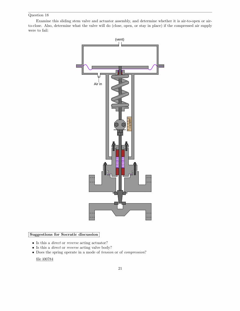
Question 18
Examine this sliding stem valve and actuator assembly, and determine whether it is air-to-open or air-to-close. Also, determine what the valve will do (close, open, or stay in place) if the compressed air supplywere to fail:
(vent)
Air in
open
Suggestions for Socratic discussion
• Is this a direct or reverse acting actuator?• Is this a direct or reverse acting valve body?• Does the spring operate in a mode of tension or of compression?
file i00784
21

Question 19
In many microwave radio systems, hollow rectangular tubes known as waveguides are often used in lieuof cables to serve as transmission lines between the transceiver and the antenna. These hollow metal tubesacts as “pipes” to convey GHz-range electromagnetic waves with great efficiency, far exceeding the efficiencyof coaxial cables:
Waveguide
RF energy in
RF energy out
Flange
Flange
The following table shows a comparison between RG-49/U waveguide and RG-9/U flexible cable:
Parameter RG-49/U waveguide RG-9/U coaxial cableExternal dimensions 2 inch × 1 inch 0.420 inch diameter
Dielectric air polyethylene (plastic)Weight 1.4 lb per foot 0.15 lb per foot
Attenuation at f = 5 GHz 0.011 dB per foot 0.23 dB per footPower rating 1.2 MW 66 W
Suppose an RG-49/U waveguide is used to transfer RF energy from a 300 watt radar transceiver to adish antenna. Calculate the RF power (in watts) available at the antenna, assuming the waveguide is 8 feetlong and that there are no other power losses between the transceiver and the antenna.
Now suppose that radar transceiver’s power is increased to 800 watts. Calculate the RF power (inwatts) available at the antenna, assuming the same waveguide length.
Now suppose that radar transceiver’s power is increased to 3 kilowatts. Calculate the RF power (inwatts) available at the antenna, assuming the same waveguide length.
Does the waveguide power loss remain constant as transmitter power increases, or does it change withthe amount of transmitted power? How does the “lost” RF energy manifest itself through the waveguide(given that the Law of Energy Conservation tells us energy cannot be created or destroyed)?
Suggestions for Socratic discussion
• Explain why the waveguide shown has such a greater power rating than the coaxial cable, based ontheir respective dB/foot loss ratings.
• Why aren’t waveguides used for all GHz-frequency radio applications, given that their power losses areso much less than the losses exhibited by coaxial cable?
• For those who have studied level measurement technologies, explain how the concept of a waveguiderelates to guided-wave radar (GWR) level transmitters.
• Is is possible for a waveguide to experience reflected signals as in the case of improperly terminatedtransmission line cables? Why or why not?
file i00791
22

Question 20
Examine the following graphs, plotting pressures along the fluid flow path within three different controlvalves:
P1
P2
Pvc
P1
P2Pvc
P1
P2Pvc
Valve #1 Valve #2 Valve #3
As you can see from the graphs, the inlet pressures (P1) and outlet pressures (P2) are the same for eachvalve. That is, each of the three valves exhibits the same amount of permanent pressure drop. However,what happens inside each valve is quite different, an indicated by the different vena contracta pressures (Pvc).
When fluid enters a constricted portion of the valve, its velocity increases. A greater fluid velocitymeans the fluid molecules possess greater kinetic energy than before. In accordance with the Law of EnergyConservation, this increase in kinetic energy must be balanced by a corresponding loss in potential energy(fluid pressure) through the constriction. This is what accounts for the sudden decrease in pressure at thevena contracta point (the point of maximum constriction inside the valve).
After passing through the constriction, the fluid enters a wider portion of the valve and slows down.Molecular kinetic energy decreases while potential energy (pressure) increases. This is why pressure“recovers” downstream of the vena contracta. The difference between upstream and downstream pressures(P1 − P2) represents fluid energy lost in the throttling action of the valve.
Determine which of the three valves has the greatest pressure recovery, and which of the three valves hasthe greatest pressure recovery factor (sometimes referred to as pressure recovery coefficient). Then, determinewhich of the three valves is more prone to cavitation in liquid service, all other factors being equal.
Finally, identify control valve types characterized by extremes of pressure recovery and pressure recoveryfactor.
file i01418
23

Question 21
This level control valve cavitates when water flows through it. A pressure profile graph shows the valve’sinlet pressure (P1), outlet pressure (P2), and vena contracta pressure (Pvc) superimposed on a dashed lineshowing the vapor pressure of the water:
LT LIC
M
25 feet
Water
LV
P1
P2
Pvc Pvapor
Pressure profile inside control valve
Inlet OutletBall/seat
P1
P2
Explain why this valve cavitates, being sure to include data from the valve’s pressure profile in yourexplanation.
24

Later, a process engineer decides to re-locate this same control valve to a lower position on the pipe.Now, even with the exact same flow rate going through the valve (Q) and the same pressure drop (P1 −P2),the valve no longer cavitates! A new pressure profile graph shows how all pressures at all points inside thecontrol valve have changed as a result of the re-location:
LT LIC
M
25 feet
Water
LV
P1
P2
Pvc
Pvapor
Pressure profile inside control valve
Inlet OutletBall/seat
P1
P2
Explain why the engineer’s solution worked, being sure to include data from the valve’s altered pressureprofile in your explanation. Also, identify at least one other change that could have been made to this processto reduce or eliminate cavitation other than re-locating the valve.
Suggestions for Socratic discussion
• Explain what the term “vapor pressure” means for a substance• Would the engineer’s solution have worked if water had been flowing the other direction through the
valve (i.e. up into the vessel rather than down out of the vessel)? Why or why not?• What type of control valve and actuator are used in this application?
file i01419
25

Question 22
Suppose this solenoid-controlled valve remains open all the time no matter which switch is pressed:
H1H2 H3H4
X1X2
To 480 VACpower source
Control powertransformer
480x120 VAC
F1 F2
A B C D
C
P E
C
P
E
Silencer
100 PSI air supply
V1
V2Solenoidvalve
Vent cap
Control valve
Open
F HE G
Close
J K
L M
F3
N P
Q
R
Relay
You measure 474 volts between terminals H1 and H4 on the transformer, and 118 volts betweenterminals M and D, with both pushbutton switches unpressed.
Identify the likelihood of each specified fault for this system. Consider each fault one at a time (i.e. nocoincidental faults), determining whether or not each fault could independently account for all measurementsand symptoms in this system. Also, identify one more possible fault not listed in the table.
Fault Possible ImpossibleFuse F3 blown (failed open)
Solenoid coil failed open“Open” switch contacts (L to M) failed open
“Close” switch contacts (J to K) failed shortedRelay coil failed shorted
Relay contact (G to P) failed shortedRelay contact (F to N) failed shortedWire open between terminals K and D
Valve V1 shutValve V2 shut
Finally, identify the next diagnostic test or measurement you would make on this system. Explain howthe result(s) of this next test or measurement help further identify the location and/or nature of the fault.
file i01425
26

Question 23
While performing an “As-Found” analysis on a control valve equipped with a smart positioner, aninstrument technician records this unusual valve signature:
0 10 20 30 40 50 60 70 80 90 100 110-10-10
0
10
20
30
40
50
60
70
80
90
100
110
What is your diagnosis of this valve signature? What physical problem(s) should the technician beginto look for when examining the valve?
Suggestions for Socratic discussion
• A useful problem-solving technique to apply to any scenario with a graph is to let the graph “tell you”what is happening step-by-step in time as you follow it from one extreme to the other. Try doingthis: starting at the lower-left corner, following the upper (red) trace step by step as though you arere-playing the opening of the valve over time, interpreting the graph in terms of stem position andactuator pressure (applied force). Describe what the graph “tells” you as you follow it from one end tothe other.
file i01424
27

Answers
Answer 1
Valve #1: Ball valve (rotary)
Valve #2: Single-ported globe valve (sliding stem)
Valve #3: Dual-ported globe valve (sliding stem)
Valve #4: Saunders valve (diaphragm)
Valve #5: Gate valve (sliding stem)
Valve #6: Butterfly valve (rotary)
Answer 2
For the single-ported valve, the force will be 150 lbs in the upward direction. For the double-portedvalve, the force will be substantially less.
Answer 3
Two points for AIC action, 1 point each for FIC actions. 3 points each for valid faults.
AIC-25 = reverse FIC-18 = reverse FIC-19 = reverse
The problem lies within the FIC-19 blower/nozzle system. Possibilities include:
• Plugged nozzle array• Plugged silencer• VFD power tripped (off)• Blower failed (not blowing air)
Answer 4
The stem packing question is a “trick”: there is no stem packing at all in this valve! The reason nopacking is required is because any leakage past the stem will simply enter the diaphragm housing and thenpass to the downstream side of the valve through the outlet pressure feedback tube, becoming part of theregulator’s out-flow. These regulators normally operate in throttling mode, and tight shut-off is not critical.
Answer 5
Partial answer:
• Packing flange: transfers force from nuts to the packing follower• Packing follower: transfers force from flange to the packing assembly• Lubrication port: lubricant is pumped in here• Lantern ring: allows even distribution of lubricant around the stem• Packing box ring: provides a flat surface at the bottom of the assembly for the upper components to
rest against
28

Answer 6
Input current Percent of range Output pressure(mA) (%) (PSI)
4 0 35.6 10 4.27.2 20 5.48 25 6
8.8 30 6.610.4 40 7.812 50 9
13.6 60 10.215.2 70 11.416 75 12
16.8 80 12.618.4 90 13.820 100 15
Follow-up question: explain the procedure for starting with a current value in milliamps and calculatingthe equivalent percentage.
Answer 7
• Iline = 0.1848 amps
• Iphase(load) = 0.1848 amps
Answer 8
Answer 9
When de-energized, the solenoid will cause the control valve to “fail” to its closed position.
Answer 10
There is absolutely no need for a termination resistor at the end of a transmission line terminating inan antenna.
Answer 11
A good diagnostic test here would be to pull the flapper away from the nozzle with your finger to see ifthe valve actuator returns to the “closed” (0%) position.
Answer 12
A good diagnostic test here would be to push the flapper toward the nozzle with your finger to see ifthe valve actuator tries to open.
29

Answer 13
• Gauge readings at 0% (3 PSI) signal to the positioner: left-hand gauge saturated high (full pressure),right-hand gauge saturated low (0 PSI)
• Gauge readings at 50% (9 PSI) signal to the positioner: too little information to given to tell. We wouldhave to know the valve’s bench set pressure range as well as any other forces acting on the stem such aspacking friction
• Gauge readings at 100% (15 PSI) signal to the positioner: left-hand gauge saturated low (0 PSI), right-hand gauge saturated high (full pressure)
Answer 14
The problem is most likely the controller, but I will let you determine the nature of the problem!
Answer 15
The normally-closed contacts are referred to as interlock contacts, and they prevent simultaneous forwardand reverse actuation of the motor.
Answer 16
When closing a gate valve, you want the gate to wedge firmly against the valve seat for tight shutoff.However, it does not matter as much whether or not the gate is fully withdrawn when the valve is wide open.
Answer 17
Any industrial example of rates-of-change (over time) or of relating one dependent variable’s change tosome other independent variable. Examples include but are not limited to:
• Flow measurement inferred from change in volume or mass over time• Pipeline pressure rate-of-change detection• Furnace temperature rate-of-change measurement• “D” action in a PID controller
Award only half-credit if the example is not industrial in nature (calculating speed of a vehicle given itsposition over time). Award no credit if the example is not quantitative (i.e. if it lacks number values).
Answer 18
Answer 19
Pantenna = 293.98 W at a transmitted power of 300 W.
Pantenna = 783.95 W at a transmitted power of 800 W.
Pantenna = 2.9398 kW at a transmitted power of 3 kW.
30

Answer 20
Pressure recovery is the pressure difference between the outlet pressure (P2) and vena contracta pressure(Pvc):
Pressure recovery = P2 − Pvc
P1
P2
Pvc
Pressure recovery
Pressure recovery factor is calculated by dividing the permanent pressure drop by the pressure dropfrom inlet (P1) to the vena contracta (Pvc):
FL =
√
P1 − P2
P1 − Pvc
Based on this definition, valve #1 has the greatest pressure recovery and the lowest FL, making it themost prone to cavitation. To avoid or reduce cavitation, it is best to use a control valve with low pressurerecovery (a high FL factor). Rotary valve designs such as ball, disk, and butterfly valves typically havegreater pressure recovery (lower FL figures) than globe valves, making them more prone to cavitation.
Ironically, control valves with low pressure recovery have high FL values. Conversely, valves with highpressure recovery have low FL values. To avoid or reduce cavitation, it is best to use a control valve with lowpressure recovery (a large FL factor). All other factors being equal (upstream and downstream pressures,flow rate, specific gravity, etc.), a valve with a large FL will have a greater vena contracta pressure (Pvc)than a valve with a small FL.
Rotary valve designs (ball, disk, butterfly, etc.) typically have greater pressure recovery (smaller FL
figures) than globe valves, making them more prone to cavitation. The reason for this greater pressurerecovery is the relatively straight and wide flow path through a rotary valve body before and after thethrottling element. Globe valves, with their more tortuous flow paths, drop more pressure along the wholevalve body. As a result, the plug/seat opening in a globe valve does not have to do all the work of droppingprocess fluid pressure.
For the same total pressure drop (P1 − P2), a globe valve’s trim will drop less pressure than a rotaryvalve’s trim of comparable Cv. This results in a greater vena contracta pressure (Pvc) inside the globe valve,making is less prone to flashing and cavitation than a comparable rotary valve.
31

The following illustration shows the difference in flow paths between a butterfly valve and a globe valve.You can see here how the globe valve design does not rely on the plug/seat restriction to be the only pointof pressure drop as is the case with the butterfly design:
Butterfly valveGlobe valve
Sharp constriction
Sharp constriction
Multiple points of constriction(drops all the pressure at
a single point in the flow path)(distributes the total pressure drop)
FL changes with valve stem position, just like Cv. For high-FL valves such as globe valves, the amountof FL change throughout the valve’s travel is slight. For low-FL valves such as butterfly valves, the amountof FL change is much greater from fully open to fully shut.
Valve trim designed to reduce cavitation typically achieves very high (near-unity) FL values. For Fisher’sCavitrol trim, the advertised FL value for two-stage trim is 0.98, and for three-stage trim it is 0.99, whichmeans Pvc is very nearly equal to P2 (downstream).
32

Follow-up question: examine the following illustrations and then explain why rotary valve designs suchas butterfly and ball valves tend to have lower FL values than comparably-sized globe valves:
Butterfly valveGlobe valve
Sharp constriction
Sharp constriction
Multiple points of constriction(drops all the pressure at
a single point in the flow path)(distributes the total pressure drop)
Answer 21
The new valve location raises absolute pressure at all points within the valve, ensuring the lowestpressure (Pvc) never drops below the water’s vapor pressure. I will let you identify other solutions.
Answer 22
Fault Possible ImpossibleFuse F3 blown (failed open)
√
Solenoid coil failed open√
“Open” switch contacts (L to M) failed open√
“Close” switch contacts (J to K) failed shorted√
Relay coil failed shorted√
Relay contact (G to P) failed shorted√
Relay contact (F to N) failed shorted√
Wire open between terminals K and D√
Valve V1 shut ?Valve V2 shut
√
In order for a “shut” V1 to account for the control valve remaining open all the time, that hand valvewould have had to be shut while the system was in a very particular condition! Simply shutting V1 underany condition(s) would not necessarily produce this effect.
A good “next test” would be to measure voltage between terminals Q and R on the solenoid.
Answer 23
This valve clearly experiences more friction as the plug nears the seat. If this is a cage-guided globe valve,I would suggest looking for interference between the piston and cage resulting from mis-alignment of theparts or poor machining. Another possibility is stem friction against the packing at that same (nearly-closedto closed) position.
33