recommended practices for treatment of …
TRANSCRIPT
IRC:
RECOMMENDED PRACTICES
TREATMENT OF EMBANKMENTAND
ROADSIDE SLOPES FOREROSION CONTROL
{FIRST REVISION)
FOR
INDIAN ROADS CONGRESS^011


IRC:56-2011
RECOMMENDED PRACTICESFOR
TREATMENT OF EMBANKMENTAND
ROADSIDE SLOPES FOREROSION CONTROL
(FIRST REVISION)
Published by:
INDIAN ROADS CONGRESSKama Koti Marg,
Sector 6, R.K. Puram,
New Delhi -110 022
MAY, 2011
Price Rs. 600/-
(Packing & postage charges extra)

IRC:56-2011
First Published
Reprinted
Reprinted
Reprinted
Reprinted
First Revision
July, 1974
March, 1991
September, 2002
August, 2005
April, 2007
May, 2011
(All Rights Reserved. No part of this publication shall be reproduced,
translated or transmitted in any form or by any means without the
permission of the Indian Roads Congress)
Printed at: Abhinav Prints, New Delhi -11 0041
(1000 Copies)
!RC:56-2011
CONTEMTSPage No.
Personnel of the Highways Specifications and Standards Committee (i)
1. Introduction 1
2. Mechanism of Surface Erosion ^ 2
3. Objective of Erosion Control 3
4. Soil Loss Analysis 6
5. Different Methods to Prevent Soil Erosion: 9
6. Bioengineering Erosion Control 25
7. Slopes in Cohesionless Soils 30
8. Slopes in Black Cotton Soils ' 31
9. Selection of Erosion Control Method 31
Annex-I 33
Annex~ll 34
Annex-Ill 36

Digitized by the Internet Arch!ive
in 2014
https://archive.org/details/govlawircy201156
IRC:56-2011
PERSONNEL OF THE HIGHWAYS SPECIFICATIONS ANDSTANDARDS COMMITTEE(As on 22"^* October, 201 0)
3.
Sinha, A.V.
(Convenor)
Puri, S.K.
(Co-Convenor)
Kandasamy, C.
(Member-Secretary)
4. Datta, P.K.
Gupta, K.K.
Sinha, S.
Kadiyali, Dr. LR.
8. Katare, P.K.
9. Jain, Dr. S.S.
10. Reddy, KSiva
11. Basu, S.B.
12. Bordoloi, A.C.
13. Ratliore, S.S.
14. Pradlnan, B.C.
15. Prasad, D.N.
16. Kumar, Ashok
17. Kumar, Kamlesli
18. Krislina, Prablnat
19. Patankar, V.L.
20. Kumar, Mahesh
21. Bongirwar, P.L.
Director General (RD) & Spl. Secretary, Ministry of
Road Transport & Highways, New Delhi
Addl. Director General, Ministry of Road Transport &Highways, New Delhi
Chief Engineer (R) S&R, Ministry of Road Transport &Highways, New Delhi
Members
Executive Director, Consulting Engg. Services (I) Pvt. Ltd.,
New Delhi
Chief Engineer (Retd.), Haryana PWD, Faridabad
Addl. Chief Transportation Engineer, CIDCO, Navi Mumbai
Chief Executive, L.R. Kadiyali & Associates, New Delhi
Director (Projects-Ill), National Rural Roads Development
Agency, (Ministry of Rural Development), New Delhi
Professor & Coordinator, Centre of Transportation Engg., IIT
Roorkee, Roorkee
Engineer-in-Chief (R&B) Andhra Pradesh, Hyderabad
Chief Engineer (Retd.), MoRT&H, New Delhi
Chief Engineer (NH) Assam, Guwahati
Principal Secretary to the Govt, of Gujarat,
R&B Deptt. Gandhinagar
Chief Engineer (NH), Govt, of Orissa, Bhubaneshwar
Chief Engineer (NH), RCD, Patna
Chief Engineer, Ministry of Road Transport & Highways,
New Delhi
Chief Engineer, Ministry of Road Transport & Highways,
New Delhi
Chief Engineer, (Retd.), Ministry of Road Transport &Highways, New Delhi
Member (Tech.), National Highways Authority of India,
New Delhi
Engineer-in-Chief, Haryana PWD, Chandgarh
Advisor L&T, Mumbai
(i)

IRC:56"2011
22. Sinha, A.K.
23. Sharma, S.C.
24. Sharma. Dr. V.M.
25. Gupta, D.P.
26. Momin, S.S.
27. Reddy, Dr. T.S.
28. Shukla. R.S.
29. Jain, R.K.
30. Chandrasekhar, Dr. BP.
31. Singh, B.N.
32. Nashkar, S.S.
33. Raju, Dr. G.V.S.
34. Alam, Parwez
35. Gangopadhyay, Dr. S.
36. Singh, Nirrnal Jit
37. Sinha, V.K.
38. Jain, N.S.
39. Yadav, Dr. V.K.
40. Chief Engineer (Pig.)
1. President, IRC
2. Director Genera! (RD) &Spl. Secretary
3. Secretary General
1. Justo, Dr. C.E.G.
2. Khattar, M.D.
3. Agarwal, M.K. v
4. Borge, V.B.
Chief Engineer, (NH), UP, PWD, Lucknow
Director General (RD) & AS (Retd.), MoRT&H, New Delhi
Consultant, AIMIL, New Delhi
Director General (RD) & AS (Retd.), MoRT&H, New Delhi
Former Member, Maharashtra Public Service Commission,Mumbai
Ex-Scientist, Central Road Research Institute, New Delhi
Ex-Scientist, Central Road Research Institute, New Delhi
Chief Engineer (Field.) Haryana PWD, Sonepat
Director (Tech.), National Rural Roads Development Agency(Ministry of Rural Development), New Delhi
Member (Tech.), National Highways Authority of India,
New Delhi
Chief Engineer (NH), PW (R), Kolkata
Chief Engineer (R&B), Andhra Pradesh, Hyderabad
Vice-President, Hindustan Constn. Co. Ltd., Mumbai
Director, Central Road Research Institute, New Delhi
Director General (RD) & SS (Retd.), MoRT&H, New Delhi
Director General (RD) & SS (Retd.), MoRT&H, New Delhi
Chief Engineer (Retd,), MoRT&H, New Delhi
Add!. Director General, DGBR, New Delhi
Ministry of Road Transport & Highways, New Delhi
EX-OfficIo Members
(Liansanga), Engineer-in-Chief and Secretary, PWDMizoram, Aizawl
(Sinha, A.V.) Ministry of Road Transport & Highways,
New Delhi
(Indoria, R.P.) Indian Roads Congress, New Delhi
Corresponding Members
Emeritus Fellow, Bangalore University, Bangalore
Consultant, Runwal Centre, Mumbai
Engineer-in-Chief (Retd.), Haryana PWD
Secretary (Roads) (Retd.), Maharashtra PWD, Mumbai
IRC:56-2011
RECOMMENDED PRACTICES FOR TREATMENT OFEMBANKMENT AND ROADSIDE SLOPES FOR EROSION CONTROL
Indian Roads Congress (IRC) had published the Guidelines 'Recommended
Practice for Treatment of Embankment Slopes for Erosion Control' (IRC:56) in the
year 1974. During the last 36 years, sufficient amount of work has been carried out
in the field of erosion control practices by various agencies and new
materials/improved techniques have been evolved. Keeping in view this aspect, the
'Embankment, Ground Improvement and Drainage Committee (H-4)' of the IRC
decided to review these Guidelines. The Committee assigned the work of revising
the same and preparing a new draft to Shri U.K. Guru Vittal and Mr. Sudhir Mathur
from CRRI, New Delhi. The draft prepared by them was discussed by H-4
Committee during its several meetings and the suggestions/modifications proposed
were incorporated in the draft. The H-4 Committee in their meeting held on
8.10.2010 approved the revised draft and referred the same to HSS Committee of
IRC.
The HSS Committee approved the document with some modifications in its4'^
meeting held on 22 October 2010. The Executive Committee of IRC approved the
modified document in its meeting held on 27 October 2010 and then the document
was placed before the IRC Council in its 19""^ meeting held on 1 1 November 2010 at
Nagpur for consideration. The Council approved the document for publication. The
composition of H-4 Committee is as given below:
1 INTRODUCTION
Kumar, Mahesh
Sharma, Arun Kumar
Mathur, Sudhir
Convenor
Co-Convenor
Member Secretary
Members
Chand, Faquir
Dhodapkar, A.N.
Gajria, Maj. Gen. K.T.
Gupta, Sanjay
Gupta, Dr. Pradeep
Jain, Naresh Chand
Rao, Prof. G.V.
Rao, P.J.
Saha, D.C.
Sangal, M.M
Sen, Samiran
Singh, R.B.

IRC:56-2011
Jain, M.K.
Jalota, Dr. A.V.
Kansal Khan, Ms. Shabana, R.K.
Korulla, Ms. Minimol
Koul, R.L
Kumar, Satander
Pradhan, B.C.
Thomas, Dr. Jimmy
Verma, Maj. V.C.
Chitra, R.
(Rep. Dir. CSMRS)
Tiwai, Dr. A.R.
(Rep. ofDGBR)
C.E., PWD, Meghalaya
President, IRC
(Liansanga)
Corresponding Members
Verma, M.S.
Ex-Officio Members
- Director General (RD) & SS, MoRTH(A.V. Sinha)
Secretary General, IRC
(R.P. Indoria)
2 MECHANISM OF SURFACE EROSION
The impact of highway location on the environment is a major concern to the
highway engineers and the public. The highways, if they are not properly located,
designed, constructed or maintained, would be subjected to erosion and may at
times contribute sediments to the stream. The control of soil and water is essential
for protection of the road structure and the conservation efforts. Therefore, highway
design, construction and maintenance procedures must be continuously evaluated
to minimise erosion and sedimentation problems. Lack of timely provision of erosion
control measures and/or inadequate workmanship accelerates the problems.
Erosion can be controlled to a considerable degree by geometric design, particularly
through aspects relating to cross - section. In some respects, the control is directly
associated with proper provision of drainage and landscape development. Thus,
effect of erosion should be considered in the planning and design stage itself. There
have been instances where many embankment slopes, irrespective of type of soil
used for their construction, have suffered a high degree of damage due to erosion
from rain and runoff. Denudation of vegetation from soil slopes or the lack of
vegetative cover on embankment slopes is often responsible for formation of rills
and rain-cuts, eventually leading to a surficial slide or to an undermining of the
edges of the road pavement structure. When vegetation grows on the slopes, there
2
IRC:56-2011
becomes available an effective dense network of root system, penetrating to a depth
of about 0.50 to 0.75m into the slope, which serves to anchor down the soil mantle
and render it resistant to erosion.
Although some standardisation of methods for minimising soil erosion in highway
construction is possible, comprehensive guidelines for control of erosion can be of a
general nature because of the wide variation in climate, topography, geology, soils,
vegetation, water resources and land use encountered in different parts of the
country. Also, erosion process is a natural phenomenon accelerated by man's
activity, technical competency in evaluating the severity of erosion problem and the
planning and design of preventive and corrective measures is essential in obtaining
economical and environmentally satisfactory methods of erosion control. This
guideline highlights some of the techniques of establishing a vegetative cover on
embankment slopes by different methods such as use of organic mulch, readymade
turfs of grass, application of jute or coir nettings, etc. In the recent past, considerable
research has been carried out in the field of 'Use of Geosynthetics' for erosion
control. There is also an emerging area of bioengineering techniques, which can
also be adopted for erosion control by field engineers. These aspects have been
kept in view while revising these guidelines. However, this guideline does not
provide details about other traditional methods which are in routine use such as the
provision of stone pitching, use of concrete blocks, etc. Additionally, this guideline
mainly covers the methods used to control/minimise erosion caused by water alone.
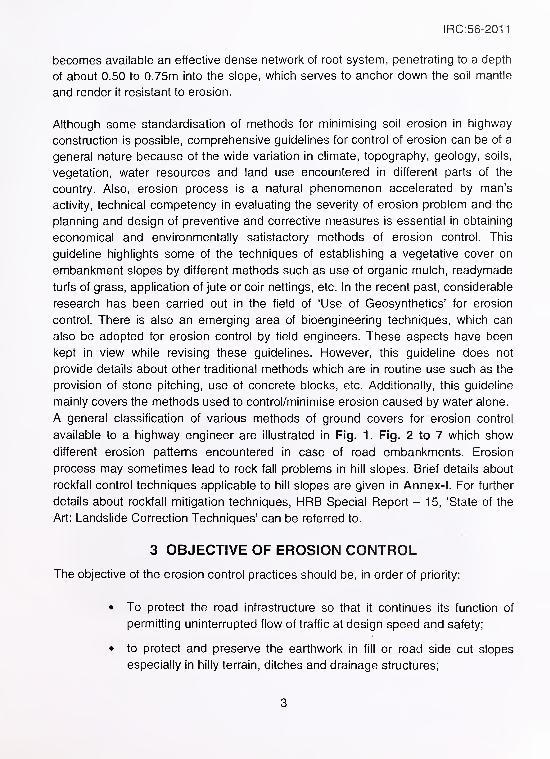
A general classification of various methods of ground covers for erosion control
available to a highway engineer are illustrated in Fig. 1. Fig. 2 to 7 which show
different erosion patterns encountered in case of road embankments. Erosion
process may sometimes lead to rock fall problems in hill slopes. Brief details about
rockfall control techniques applicable to hill slopes are given in Annex-I. For further
details about rockfall mitigation techniques, HRB Special Report - 15, 'State of the
Art: Landslide Correction Techniques' can be referred to.
3 OBJECTIVE OF EROSION CONTROL
The objective of the erosion control practices should be, in order of priority:
• To protect the road infrastructure so that it continues its function of
permitting uninterrupted flow of traffic at design speed and safety;
• to protect and preserve the earthwork in fill or road side cut slopes
especially in hilly terrain, ditches and drainage structures;
3
IRC:56-2011
Gunite
Concrete Lining
'FabrI form' Blanl<ets
Articulated Blocl<s
Gabion IVIattress
Gravel Layer
Stone pitching (Rip-rap)
Cellulose Fibres
Straw, Hay and WoodChips
2 - D Meshes and Nets
(Polymeric & natural
Fibre)
3-D Mats and cellular
WebsGrasses and legumes
Deep Rooted Plants
Bitumen Cutback
Bitumen Emulsion
Fig. 1 Classification of Ground Covers for Erosion Control
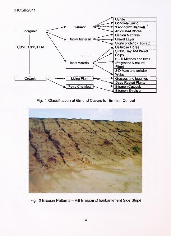
Fig. 2 Erosion Patterns - Rill Erosion of Embankment Side Slope
4
IRC:56-2011
IRC:56-2011
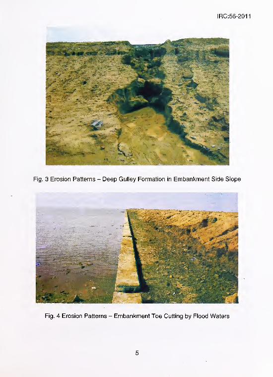
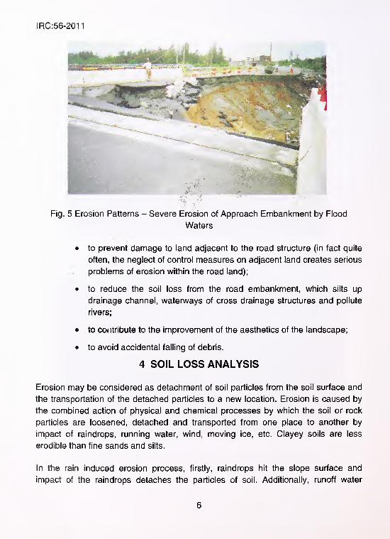
Fig. 5 Erosion Patterns - Severe Erosion of Approach Embankment by Flood
Waters
• to prevent damage to land adjacent to the road structure (in fact quite
often, the neglect of control measures on adjacent land creates serious
problems of erosion within the road land);
• to reduce the soil loss from the road embankment, which silts up
drainage channel, watenA/ays of cross drainage structures and pollute
rivers;
• to contribute to the improvement of the aesthetics of the landscape;
• to avoid accidental falling of debris.
4 SOIL LOSS ANALYSIS
Erosion may be considered as detachment of soil particles from the soil surface and
the transportation of the detached particles to a new location. Erosion is caused by
the combined action of physical and chemical processes by which the soil or rock
particles are loosened, detached and transported from one place to another by
impact of raindrops, running water, wind, moving ice, etc. Clayey soils are less
erodible than fine sands and silts.
In the rain induced erosion process, firstly, raindrops hit the slope surface and
impact of the raindrops detaches the particles of soil. Additionally, runoff water
6
IRC:56-2011
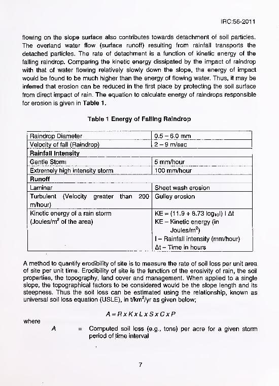
flowing on the slope surface also contributes towards detachment of soil particles.
The overland water flow (surface runoff) resulting from rainfall transports the
detached particles. The rate of detachment is a function of kinetic energy of the
falling raindrop. Comparing the kinetic energy dissipated by the impact of raindrop
with that of water flowing relatively slowly down the slope, the energy of impact
would be found to be much higher than the energy of flowing water. Thus, it may be
inferred that erosion can be reduced in the first place by protecting the soil surface
from direct impact of rain. The equation to calculate energy of raindrops responsible
for erosion is given in Table 1
.
Table 1 Energy of Falling Raindrop
Raindrop Diameter 0.5-6.0 mmVelocity of fall (Raindrop) 2-9 m/sec
Rainfall Intensity
Gentle Storm 5 mm/hour
Extremely high intensity storm 1 00 mm/hour
Runoff
Laminar Sheet wash erosion
Turbulent (Velocity greater than 200
m/hour)
Gulley erosion
Kinetic energy of a rain storm
(Joules/m^ of the area)
KE = (11.9 + 8.73 logiol) 1 At
KE - Kinetic energy (in
Joules/m^)
1- Rainfall intensity (mm/hour)
At - Time in hours
A method to quantify erodibility of site is to measure the rate of soil loss per unit area
of site per unit time. Erodibility of site is the function of the erosivity of rain, the soil
properties, the topography, land cover and management. When applied to a single
slope, the topographical factors to be considered would be the slope length and its
steepness. Thus the soil loss can be estimated using the relationship, known asuniversal soil loss equation (USLE), in t/km^/yr as given below;
A=RxKxLxSxCxPwhere
A = Computed soil loss (e.g., tons) per acre for a given storm
period of time interval
7
IRC:56-2011
CP
R
KL andS
Precipitation (Erosion potential of rainfall, in mm per unit
time period)
Soil erodibility value
Topographic factors (Slope length factor and slope
steepness factor)
Vegetation crop factor
Erosion control practice factor
This universal soil loss equation was updated and 'Revised Universal Soil Loss
Equation (RUSLE)' was given by Renard et al., in 1997. A principal modification is in
R factor which includes rainfall and runoff erosivity factor (runoff erosivity also
includes snow melt where runoff is significant).
For protection of a road embankment running along a river course or for protection
of bridge abutments close to river edge, bank protection measures are sometimes
required to be adopted. Riprap with properly designed apron is generally used as a
liner for streams, rivers and channels subjected to high-velocity flow and for lake,
reservoir and channel banks subject to wave action. Geotextiles are an effective and
economical alternative to conventional graded filters which are placed under the
stone riprap. However, for aesthetic or economic reasons, articulated concrete
mattresses, gabions or precast cellular blocks or geotextile bags can also be used to
cover the geotextile. The velocity of the current, the height and frequency of waves
and the erodibility of the bank need to be considered while designing bank
protection. Extensive soil conservation and watershed management play an
important role in reducing sediment discharge from watersheds. Special construction
measures, other than vegetation growth on slope, include compaction of slope and
provision of revetment protection such as using stone or bricks, placement of
fascines, etc. These are designed to break up energy of flowing water and prevent
migration of particles by reducing the threshold velocity of erosion. For more details
regarding river bank protection, IRC:89 "Guidelines for Design & Construction of
River Training and Control Works for Road Bridges" may be referred.
4.2 Provision of Kerb Drains and Chutes in Embankments
The problem of erosion of slopes and shoulders is most severe in high
embankments having steep longitudinal gradient, when the embankment has been
built with erodible soil, without proper longitudinal and cross drains. The erosion
problems in such embankments become acute when the side slopes are
4.1 River Bank Erosion
8
IRC:56-2011
unprotected. In such a case, water gains velocity and eventually when it leaves the
roadway at any random location, it may cause serious erosion of slopes manifesting
in the form of deep gulleys extending right upto carriageway. Sometimes such
problems may undermine road pavement also. The quantum of runoff water
becomes considerable in case of four lane roads with paved shoulders, especially in
curved sections of the road, where unidirectional camber is provided. This mayresult in accumulation of huge quantity of runoff water from both carriageways
towards one side of the embankment side slope, thereby increasing the severity of
the erosion by many times. Therefore in such instances, a system of proper kerb,
channel and median drains coupled with chutes should be provided to drain off the
rain water from the road embankments. For more details in this regard, IRC:SP:42
"Guidelines on Road Drainage' and 1RC:SP:50, "Guidelines on Urban Drainage"
may be referred to.
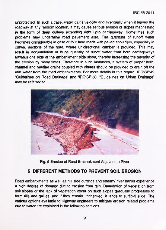
Road embankments as well as hill side cuttings and stream/ river banks experience
a high degree of damage due to erosion from rain. Denudation of vegetation from
soil slopes or the lack of vegetation cover on such slopes gradually progresses to
form rills and gullies, and if they remain unchecked, it leads to surficial slide. The
various options available to Highway engineers to mitigate erosion related problems
due to water are explained in the following sections.
Fig. 6 Erosion of Road Embankment Adjacent to River
5 DIFFERENT METHODS TO PREVENT SOIL EROSION
9
IRC:56-2011
5.1 Simple Vegetative Turfing
Erosion is often a problem when there is not enough protective cover on steep
slopes or in drainage channels that have been designed to rely on vegetation for
long term erosion control. Vegetation is ideal for erosion control because it is
relatively inexpensive to establish and maintain and it presents aesthetically
appealing look. Vegetative turfing has proved to be, by and large, the most
economical and simple means of protecting slope of hills and embankments against
erosion. Obviously, this method should be adopted where the soil has enough
nutrients and the environmental conditions are conducive to promote vegetation
growth. The method consists of preparing the slope area into seedbeds by grading
the slope to the extent possible and subsequently broadcasting the seeds or
saplings/plant roots of promising types of locally available plants. In case the slope
has pockets of enriched and poor soils in relation to promotion of vegetation, putting
seeds in isolated pockets of specially enriched soil should encourage plantation. The
rest of the slope should be treated with some other techniques described in this
guideline.
On the basis of field studies, it has been established that shallow surficial slides
constitute a significant proportion of landslides in the areas with moderate rainfall
intensity and with a soil cover of medium cohesive type. Most of these surficial
landslides occur as a result of loss of vegetation cover on soil slopes due to a cut
being made for road construction. Surficial slides extend to only a shallow depth
below the slope surface and originate as a result of erosion due to flowing water. If
erosion is allowed to proceed unchecked, there is every possibility that the damage
may spread laterally or the depth of erosion may increase, eventually resulting in a
much larger damaged slope area. Vegetative turfing represents one of the most
important corrective measures in such cases. In the case of freshly exposed cutting
made for road construction, vegetative turfing is important, even as a preventive
measure. In the case of deep seated slides, however, vegetative turfing is only one
of the several corrective measures which should be adopted and as such it can
prove to be effective only when implemented along with other corrective measures.
The joint action of trees, grass and other plant species for protection of soil from
water and wind erosion has been recognised from several documented studies. The
above ground biomass of the trees and plants provide adequate canopy interception
to the falling rain drops and saves the soil from splash erosion, while the mass of
litter and Rhizomes act as speed breakers for the running water on the slope.
10

IRC:56-2011
Besides soil protection, grass plays a significant role in binding the soil particles with
their fibrous root system. The root system of different plant species varies and its
mass increases with the age of the plant. The protective mechanism of vegetation in
preventing surficial erosion can be summarised as given below:
a) Interception: Foliage and plant residues absorb rainfall energy and
prevent soil detachment due to raindrop splash
b) Restraint: Root systems physically bind or restrain soil particles
while above ground part of the vegetation filter sediments from the
runoff.
c) Retardation: Stems and foliage increase surface roughness and
slow down velocity of runoff
d) Infiltration: Plants and their residues help to maintain porosity and
permeability thereby promoting infiltration and delaying onset of
runoff
Deep rooted vegetation helps to prevent shallow mass movement by:
• Reinforcement of the soil by the root system
• Soil water depletion through transpiration and adsorption
• Buttressing and soil arching action from embedded stems
Laboratory and analytical studies carried out concerning the role of vegetation in
improving the stability of slopes, have established that, the binding effect of roots
impart to the soil, cohesive strength of about 2.0 to 2.5 tonnes/sqm. Assuming an
effective depth of penetration of 0.5 m and increase in cohesive strength of
2.0 tonnes/sqm, analysis of slope with normal geometry has shown a significant
increase in the factor of safety for a slope height of about 6 m. Thus, by providing a
vegetative cover, not only the erosion of the soil is checked, but also the possibility
of shallow slope failure is prevented, due to the strengthening of the top 0.5 m depth
of the soil slope. Some typical deep-rooted species of grasses and shrubs suited to
different topographical areas of our country are given in Annex-ll. These species
can be adopted for turfing of denuded slopes.
However, there are certain limits to the successful application of vegetative turfing
method. This method may fail in the following situations:
1) On highly erodible slopes where seeding or sprigging is liable to be
washed down before they have had time to take root.
11
IRC:56-2011
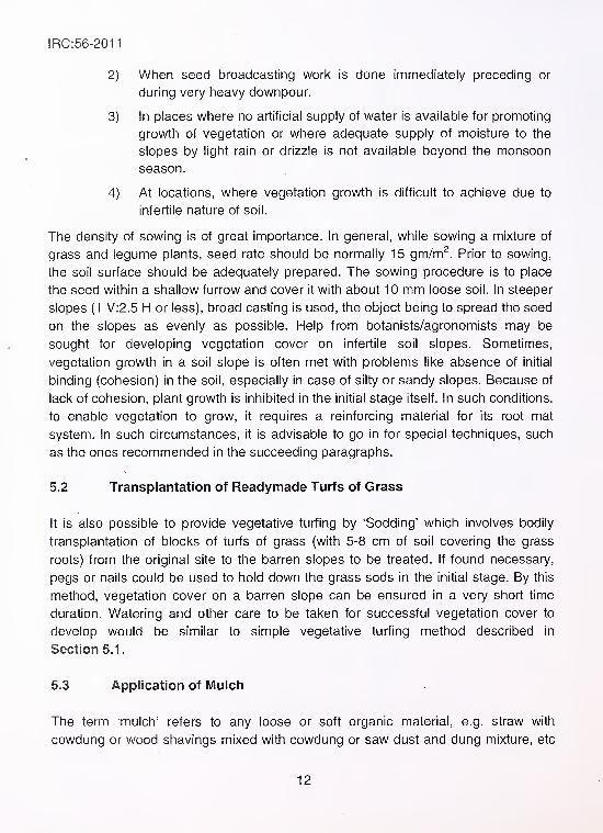
2) When seed broadcasting work is done immediately preceding or
during very heavy downpour.
3) In places where no artificial supply of water is available for promoting
growth of vegetation or where adequate supply of moisture to the
slopes by light rain or drizzle is not available beyond the monsoon
season.
4) At locations, where vegetation growth is difficult to achieve due to
infertile nature of soil.
The density of sowing is of great importance. In general, while sowing a mixture of
grass and legume plants, seed rate should be normally 15 gm/m^. Prior to sowing,
the soil surface should be adequately prepared. The sowing procedure is to place
the seed within a shallow furrow and cover it with about 10 mm loose soil. In steeper
slopes (1 V:2.5 H or less), broad casting is used, the object being to spread the seed
on the slopes as evenly as possible. Help from botanists/agronomists may be
sought for developing vegetation cover on infertile soil slopes. Sometimes,
vegetation growth in a soil slope is often met with problems like absence of initial
binding (cohesion) in the soil, especially in case of silty or sandy slopes. Because of
lack of cohesion, plant growth is inhibited in the initial stage itself. In such conditions,
to enable vegetation to grow, it requires a reinforcing material for its root mat
system. In such circumstances, it is advisable to go in for special techniques, such
as the ones recommended in the succeeding paragraphs.
5.2 Transplantation of Readymade Turfs of Grass
It is also possible to provide vegetative turfing by 'Sodding' which involves bodily
transplantation of blocks of turfs of grass (with 5-8 cm of soil covering the grass
roots) from the original site to the barren slopes to be treated. If found necessary,
pegs or nails could be used to hold down the grass sods in the initial stage. By this
method, vegetation cover on a barren slope can be ensured in a very short time
duration. Watering and other care to be taken for successful vegetation cover to
develop would be similar to simple vegetative turfing method described in
Section 5.1.
5.3 Application of Mulch
The term 'mulch' refers to any loose or soft organic material, e.g. straw with
cowdung or wood shavings mixed with cowdung or saw dust and dung mixture, etc
12

IRC:56-2011
laid down on the slopes to protect the roots of plants. In the case of embankments
which are less than 3 m high, where the severity of the erosion problem is not of a
high order, the mulch application would be very helpful for vegetation growth. The
approximate thickness of mulch cover should be 2.5 cm. The organic mulch
covering the soil slopes can be held in place and made resistant to being washed
downhill or being blown away by pegging them down with bamboos, at suitable
intervals, in a grid pattern and also laying bamboos horizontally connecting the pegs
and thus forming the grid.
5.4 Vetlver Grass (Botanical name: Chrysopogon Zizanioides)
Vetiver is a special type of grass which can be grown in a wide variety of soil such
as clayey, sandy, silty, gravely types or in other words from least erodible to highly
erodible soils. This type of grass does not require any special maintenance. Vetiver
is capable of growing in wide range of climates ranging from 300 mm annual rainfall
to over 6000 mm annual rainfall and from -14°C to more than 50°C of soil
temperature. Moreover, it can withstand long and sustained drought for more than
six months.
The stabilisation and protection of slope by vetiver grass is effective, efficient and
low cost vis-a-vis other traditional methods of erosion control like stone rip-rap.
Vetiver grass penetrates vertically below to considerable depths into the sub-soil, its
roots have a significant strength and thereby improve the shear strength of sub-soil
at a depth of 0.5 m by as much as 40 percent. For best result, the vetiver root
divisions, or slips, should be planted in a double or triple line to form parallel hedges
across the erosion prone slope. Distance between consecutive hedge rows can be
kept between 30 to 50 cm. The slips should be planted at the beginning of the rainy
season to ensure that they get full benefit of the soil moisture. Planting operations of
vetiver slips is similar to planting of rice seedlings. The next slip is planted 10 to
15 cm from the already planted slip along the same contour furrow and the process
is repeated upto required length to cover the entire area. Once the hedge has been
established at the slope, only care needed is annual trimming, if required.
13
IRC:56-2011
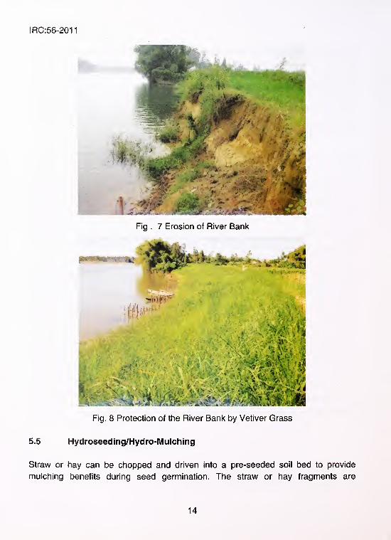
Fig . 7 Erosion of River Banl<
Fig. 8 Protection of the River Bank by Vetiver Grass
5.5 Hydroseeding/Hydro-Mulching
Straw or hay can be chopped and driven into a pre-seeded soil bed to provide
mulching benefits during seed germination. The straw or hay fragments are
14
IRC:56-2011
sometimes secured to the ground surface by crimping, punching, tacking or netting,
but often mulch is not secured firmly to the ground. Hence integrity of these mulches
can be severely affected by rain, wind, surface runoff and animal/ human
trespassing. As a result, conventional mulches provide few weeks of protection to
the bare soil, often making grading and reapplication necessary. To overcome such
shortfall, the technique of Hydroseeding (also known as Hydro-mulching) was
developed.
Hydroseeding is a process which can be considered as alternative to sodding. It
involves seed application in a water based slurry via a high pressure pump and
hoses or a spray gun. The basic ingredients used in this process are water, seeds,
fertiliser, mulch, tackifier and bio-stimulant. Mulch can be made from recycled paper
or shredded wood or a mixture of both - wooden mulch breathes while paper mulch
forms a protective cover. Chopped straw cut to a length of 10 to 20 mm can also be
used as mulch. Tackifier is required to make this mulch and seed stick to the soil
surface to which it is being applied. Mulch protects the slope until the seed
germinates and provides organic nutrients as the vegetation grows. These mixed
ingredients are stored in a tank and applied using a pressure pump, on barren land
surface on which vegetation is to be promoted. Hydroseeding method can also be
used by adopting cellulose based fibrous mulches. Cellulose based fibrous mulches
are spray applied with the seed in this method. The fibres are dispersed in a solution
that, when sprayed on bare soil, t^auses the fibres to stick to each other and to the
soil. Hydroseeding method is specially suited for vertical or near vertical soil slopes
(steep slopes) on which 'simple vegetative turfing' or manual application of mulch
would not be successful. Hydroseeding job is specialised and expensive but for
some inaccessible slopes, it offers the only practical method.
5.6 Promotion of Vegetative Turfing by Using Jute Netting
Many field experiments have been successfully carried out in different parts of the
country under varying climatic conditions on manmade embankments and natural
slopes using jute netting (also known as open weave jute geotextile) for promotion of
vegetation and control of soil erosion. The method involves laying the jute netting
firmly on the prepared slope after sowing seeds of suitable vegetation.
Before laying jute netting, the slopes which are being treated are to be initially
demarcated, graded and fertilised. The levelling of the area must be carried out so
that when netting is laid it may cover the entire area flush to the ground ensuring
15
IRC:56-2011
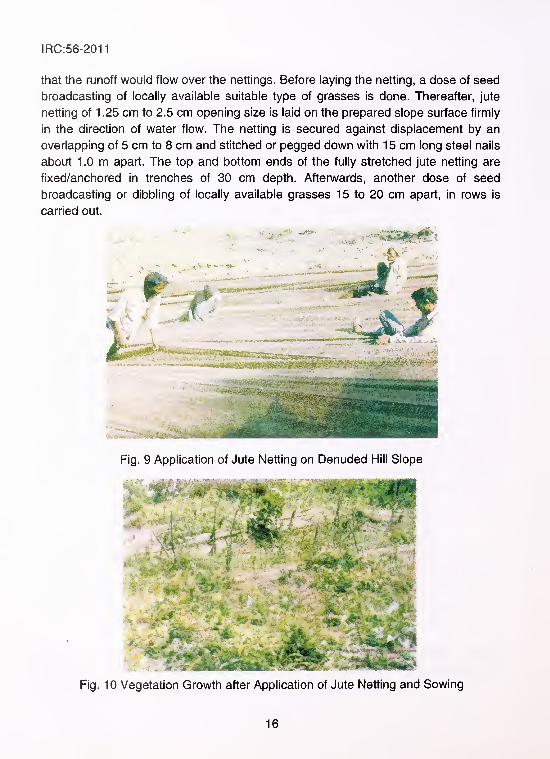
that the runoff would flow over the nettings. Before laying the netting, a dose of seed
broadcasting of locally available suitable type of grasses is done. Thereafter, jute
netting of 1 .25 cm to 2.5 cm opening size is laid on the prepared slope surface firmly
in the direction of water flow. The netting is secured against displacement by an
overlapping of 5 cm to 8 cm and stitched or pegged down with 15 cm long steel nails
about 1 .0 m apart. The top and bottom ends of the fully stretched jute netting are
fixed/anchored in trenches of 30 cm depth. Afterwards, another dose of seed
broadcasting or dibbling of locally available grasses 15 to 20 cm apart, in rows is
carried out.
ItfiliiiiliiiiMiii^^
Fig. 9 Application of Jute Netting on Denuded Hill Slope
Fig. 10 Vegetation Growth after Application of Jute Netting and Sowing
i
16
IRC:56-2011
The jute net acts as a series of miniature checi< dams, thus, absorbing the force of
impact and dissipating the kinetic energy of surface runoff, and thereby reducing its
erosion potential. The soil particles, seed, grass root slips are held securely in their
original locations without being dislodged, due to provision of jute nettings. Jute
netting absorbs water upto four times its dry weight and transfers it to soil, thereby,
giving full benefit of moisture for growth of vegetation. After the first rainy season,
the seeded and sprigged vegetation soon envelops the entire surface thus,
protecting the slopes against erosion. Jute netting has been observed to have a life
of about 1 to 2 years in the field, which is sufficient for fully promoting the growth of
vegetation cover on the denuded slopes. Once vegetation growth has been
established within two monsoon seasons, the mission is accomplished for the jute
netting. At the end of jute netting's life, the geogrid decomposes and in the process
adds nutrients to the soil. For more details and specifications of this technique,
IS: 14986 'Guidelines for Application of Jute Geotextile for Rain Water Erosion
Control in Road and Railway Embankments and Hill Slopes' may be referred to.
5.7 Use of Coir Netting
Coir netting (also known as 'Coir Bhoovastra') is another type of biodegradable
material which can be effectively used in a manner similar to jute nettings. Coir
nettings degrade much slower than jute nettings (expected field life of about 2 to 3
years) and thus provide protection to the slopes for a longer time than jute nettings.
Coir is also resistant to saline water and provides an ecological niche for a rapid
re-establishment of the vegetation cover. Coir resembles natural soil in its capacity
to absorb solar radiation. This means that there is no risk of excessive heating as it
happens sometimes in the case of synthetic nettings. In a manner similar to jute
nettings, coir netting also breaks up runoff from heavy rains and dissipates the
energy of flowing water. Coir also promotes the growth of new vegetation by
absorbing water and preventing the top soil from drying out. However, compared to
Jute nettings, drapability of coir netting is lesser and their water absorption capability
is also lower than jute nettings. Coir nettings are available in densities varying from
400 to 1400 gm/m^ (higher density means a tighter mesh and less open area in the
netting). The length of the rolls would be 50 m and width can be between 1 to 4 m.
For more details and specifications about use of coir nettings, IS: 15869 'Open
weave coir Bhoovastra-Specification' and iS 15872 'Application of Coir Geotextiles
(coir woven Bhoovastra) for Rain Water Erosion Control in Roads, Railway
Embankments and Hill Slopes-Guidelines' may be referred to.
17
IRC:56-2011
5.8 Erosion Control Using Two Dimensional (2-D) Synthetic Geogrids/
Netting
With the provision of polymer geogrid mesh for root reinforcement, extremely high
density of grass growth can be achieved. Geogrid reinforced slope protection has
been shown to provide erosion protection equivalent to 250 mm thick revetment and
is treated as an attractive cost-effective alternative solution. Under erratic weather
conditions, successful vegetation growth and its maintenance depends on un-
seasonal rainfall and hence longer life of reinforcing material would be required for
ensuring vegetation growth apart from contribution from the mesh towards reduction
in velocity of surface runoff. Most ordinary turfing as well as agro based nettings
may fail to provide erosion prevention in areas which experience repetitive change in
climate, prolonged drought in particular. Use of polymer geogrid mesh provides a
permanent protection as it is not biodegradable. When compared with such similar
root reinforcing concepts by using natural fibres, it compares very favourably,
because of its longer life and almost unfailing success rate for vegetation growth
year after year.
The peak tensile strength or tensile strength at 10 percent strain, whichever is lower,
of the polymeric geogrid to be used for erosion control should not be less than 4
kN/m when tested as per ASTM D 5035 (minimum average roll value in machine
direction). Geogrid mesh shall be stabilised against ultraviolet ray degradation for
continuous exposure of about 10 years (defined as retaining 75 percent of its
original strength after 10 years of exposure) using finely divided carbon black (ASTM
D 4355 - 500 hour exposure). The installation and seed broadcasting procedures
would be similar to jute nettings.
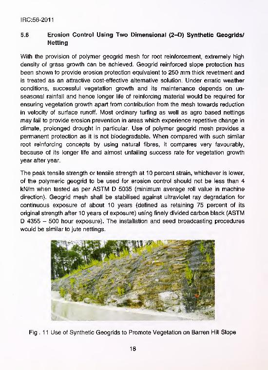
Fig . 1 1 Use of Synthetic Geogrids to Promote Vegetation on Barren Hill Slope
18
IRC:56-2011
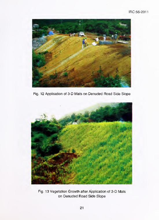
5.9 Three Dimensional Erosion Control Mat/Rolled Erosion Control
Products
Relying upon vegetation growth alone may be sometimes very unpredictable and
unreliable as it may be extremely difficult to achieve 100 percent vegetation
coverage, leaving exposed areas vulnerable to erosion. Furthermore, vegetation
may sometimes dry up or become diseased, reducing its erosion control capability.
Reinforced vegetation (or reinforced grass) is a better method that is being practiced
for enhancing slope stability and erosion control. The synthetic materials that have
been employed in reinforced grass technique have two forms. They can be two
dimensional polymeric meshes, a mesh being an extruded net with apertures to
allow grass growth. This product was explained in section 5.8. Alternatively, they
can be three dimensional mats, these being multi-filamented materials having
specified thickness. Such materials are also known as Rolled Erosion Control
Products (RECPs). 3-D Mats/RECPs can also be made using biodegradable natural
fibres such as straw, jute, coir or wood shavings (used individually or in combination)
stuffed into polymeric or organic nettings on either side to form a mat or blanket like
structure. Obviously when mats are made using natural fibres, they would be
biodegradable also, but they don't provide everlasting protection. RECPs are used in
combination with seed beds to enhance the establishment of vegetation. Whengeosynthetic mattings (3-D Mats) are made exclusively from polymeric substances,
they consist of UV stabilised synthetic fibres and filaments processed into
permanent, high strength, three dimensional (3-D) matrices, installation procedure
involves levelling and preparation of the surface to be treated, rolling out and
fastening the geosynthetic mat in intimate contact with the soil sufface, then in-filling
with fine soil and a prescribed seed mix. Seed can be applied to the surface either
before or after the mat is installed and the vegetation will develop unhindered by the
matrix. A geosynthetic mat installed in this manner is also called as 'Turf
Reinforcement Mat (TRM)'. Polymeric mats are used in situations where these
products are required to last a long time. Other way of installation involves direct
deployment of the material over a freshly seeded soil surface. This allows the
natural sedimentation process to in-fill the mat, allowing a more gradual
development of a reinforced vegetation cover.
Steel wire mesh is sometimes included in these mats optionally where these mats
are required to possess more strength against erosive forces, like steeper slopes or
in heavy rainfall areas. The three dimensional mats shall be anchored to the surface
to be protected using staples or pins. The 3-D mat increases the soil's resistance to
19
IRC:56-2011
erosion by providing an environment that enhances the growth of vegetation through
the mat. Initially the mat works to shield the soil from washing out before the
vegetation has a chance to become established. Then as the vegetation matures,
the roots anchor the mat to the soil to provide superior soil reinforcement strength,
capable of handling greater volumes of runoff water and higher flow velocities.
The three dimensional mat solutions protect the soil surface by:
• Providing immediate protection of exposed areas from direct effects
of wind and rainfall impact
• Protecting seeded topsoil from washing out before vegetation has
established
• Creating an environment that enhances the growth of vegetation
through the mat
• Reinforcing the root system of plants, further binding the soil surface
. and increasing shear resistance of the surface
• Reducing the velocity and volume of runoff flow by increasing water
percolation into the soil
• The steel wire mesh (optional) helps in the retention of gravel sized
particles and also acts as an additional reinforcement.
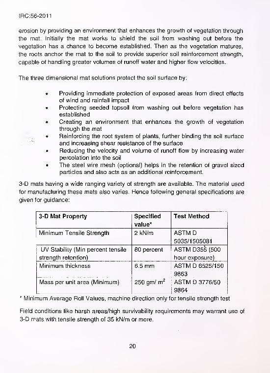
3-D mats having a wide ranging variety of strength are available. The material used
for manufacturing these mats also varies. Hence following general specifications are
given for guidance:
3-D Mat Property Specified
value*
Test l\/lethod
Minimum Tensile Strength 2 kN/m ASTM D
5035/1505081
UV Stability (Min percent tensile
strength retention)
80 percent ASTM D355 (500
hour exposure)
Minimum thickness 6.5 mm ASTM D 6525/150
9863
Mass per unit area (Minimum) 250 gm/ m^ ASTM D 3776/50
9864* Minimum Average Roll Values, machine direction only for tensile strength test
Field conditions like harsh areas/high survivability requirements may warrant use of
3-D mats with tensile strength of 35 kN/m or more.
20
IRC:56-2011
Fig. 13 Vegetation Growth after Application of 3-D Mats
on Denuded Road Side Slope
21
IRC:56-2011
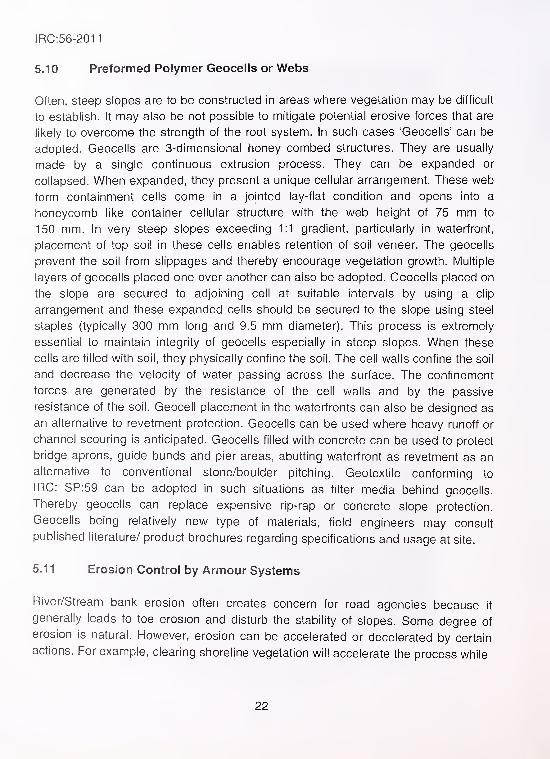
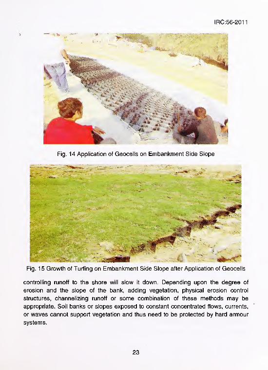
5.10 Preformed Polymer Geocells or Webs
Often, steep slopes are to be constructed in areas where vegetation may be difficult
to establish. It may also be not possible to mitigate potential erosive forces that are
likely to overcome the strength of the root system. In such cases 'Geocells' can be
adopted. Geocells are 3-dimensional honey combed structures. They are usually
made by a single continuous extrusion process. They can be expanded or
collapsed. When expanded, they present a unique cellular arrangement. These web
form containment cells come in a jointed lay-flat condition and opens into a
honeycomb like container cellular structure with the web height of 75 mm to
150 mm. In very steep slopes exceeding 1:1 gradient, particularly in waterfront,
placement of top soil in these cells enables retention of soil veneer. The geocells
prevent the soil from slippages and thereby encourage vegetation growth. Multiple
layers of geocells placed one over another can also be adopted. Geocells placed on
the slope are secured to adjoining cell at suitable intervals by using a clip
arrangement and these expanded cells should be secured to the slope using steel
staples (typically 300 mm long and 9.5 mm diameter). This process is extremely
essential to maintain integrity of geocells especially in steep slopes. When these
cells are filled with soil, they physically confine the soil. The cell walls confine the soil
and decrease the velocity of water passing across the surface. The confinement
forces are generated by the resistance of the cell walls and by the passive
resistance of the soil. Geocell placement in the waterfronts can also be designed as
an alternative to revetment protection. Geocells can be used where heavy runoff or
channel scouring is anticipated. Geocells filled with concrete can be used to protect
bridge aprons, guide bunds and pier areas, abutting waterfront as revetment as an
alternative to conventional stone/boulder pitching. Geotextile conforming to
IRC: SP:59 can be adopted in such situations as filter media behind geocells.
Thereby geocells can replace expensive rip-rap or concrete slope protection.
Geocells being relatively new type of materials, field engineers may consult
published literature/ product brochures regarding specifications and usage at site.
5.1 1 Erosion Control by Armour Systems
River/Stream bank erosion often creates concern for road agencies because it
generally leads to toe erosion and disturb the stability of slopes. Some degree of
erosion is natural. However, erosion can be accelerated or decelerated by certain
actions. For example, clearing shoreline vegetation will accelerate the process while
22
IRC:56-2011
Fig. 14 Application of Geocells on Embankment Side Slope
Fig. 15 Growth of Turfing on Embankment Side Slope after Application of Geocells
controlling runoff to the shore will slow it down. Depending upon the degree of
erosion and the slope of the bank, adding vegetation, physical erosion control
structures, channelizing runoff or some combination of these methods may be
appropriate. Soil banks or slopes exposed to constant concentrated flows, currents,
or waves cannot support vegetation and thus need to be protected by hard armour
systems.
23
IRC:56-2011
The erosion control structures for bank protection are as follows:
1) Rip-rap - Comprises of stone of different sizes (conforming to
specified gradation) placed against the river bank to deflect the
force of the water hitting the banks. Stone pitching refers to
placement of approximately single sized rocks along the slope to
serve the same purpose.
2) Retaining walls, toe-walls or break walls and sheet piles that are
placed in such a way to form a barrier between the shore and the
water front.
3) Gabion baskets/revet mattresses that are filled with stones of
specified size and provided on slopes
4) Geotextile Bags - Bags made from geotextile material, which are
filled with sand/suitable type of soil and are kept on the slopes in
place of stone pitching
When a hard armour system is in place, water can seep in and out of the bank or
slope, but the force of water is resisted by the armour. As the water seeps, it can
gradually carry soil particles along with it. The resulting voids cause armour support
to be lost after some time. This process is called 'piping' which can culminate in
shifting, rolling, or other instability in the hard armour system. Typical solutions
include placing a filter layer between the bank soil and the armour to prevent piping.
Traditional filter layers have been graded sand and aggregate which are very costly
because they are constructed from select graded materials. Also, the filter layer
must be of a controlled thickness. On a steep slope, it can be very difficult to
properly construct such aggregate filter layers.
Geotextiles have become .standard filter layers for hard armour systems because
they overcome the drawbacks of graded sand and aggregate filters. These are
manufactured with specific hydraulic and soil retention properties to suit the soil that
needs protection. Also, they can be installed with ease on slopes, even under water.
Specifications and other details about provision of geotextile layer below such
armour protection system can be obtained from IRC SP:59, 'Guidelines for Use of
Geotextiles in Road Pavements and Associated Works'. Details about river bank
erosion control techniques can be obtained from 'IRC:89, Guidelines for Design and
Construction of River Training and Control Works for Road Bridges' and from
MoRTH Specifications for Road and Bridge Works. Brief details about gabions/revet
mattresses are given in Annex, ill.
24
IRC:56-2011
6 BIOENGINEERING EROSION CONTROL
Stream bank and embankment side slope erosion can be severe, in cases wliere
sliorelines are composed of easily erodible soil and where the road runs along the
stream. Traditional methods of controlling stream flow and wave induced erosion
have relied on structural practices like rip-rap, retaining walls and sheet piles. In
many cases these methods are expensive or may be ineffective. An alternative
approach is bioengineering, a method of construction using live plants alone or
combined with dead or inorganic materials, to produce living, functioning systems to
prevent erosion, control sediment and provide habitat. Bioengineering involves the
use of live plants to add structural strength to soil.
Advantages of bioengineering solutions are:
1) Low cost and lower long-term maintenance cost than traditional
methods
2) Low maintenance requirement of live plants after they are
established
3) Environmental benefits of wildlife habitat, water quality
improvement and aesthetics
4) Improved strength over time as root systems develop and increase
structural stability
5) Compatibility with environmentally sensitive sites with limited
access.
Limitations of bioengineering methods include:
1) Installation season is often restricted to plant dormant seasons,
when site access is limited
2) The availability of locally adapted plants may be limited
3) Labour needs are intensive and skilled, experienced labour maynot be available
4) Installers may not be familiar with bioengineering principles anddesigns (untrained)
Plants that root quickly are used in a variety of ways to control erosion. There are
several ways in which bioengineering solutions can be implemented for protection
against erosion as explained in following sections.
6.1 Contour Wattling
One bioengineering technique that has been successfully used is called 'wattling'. It
is a bundle of dormant stem cuttings tied together. When the wattles are planted in a
bank along a contour, they sprout a continuous line of roots and shoots (resembling
25
IRC:56-2011
a retaining wall of plants) and quickly stabilises the soil than individual plants. Within
a few years, the "sprouts" look like a tree lining/continuous row of shrubs.
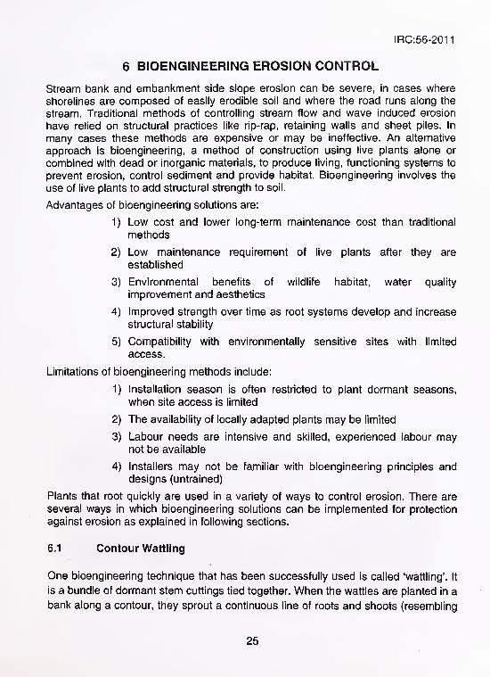
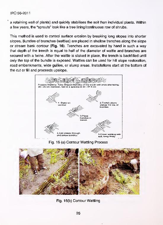
This method is used to control surface erosion by breaking long slopes into shorter
slopes. Bundles of branches (wattles) are placed in shallow trenches along the slope
or stream bank contour (Fig. 16). Trenches are excavated by hand in such a way
that depth of the trench is equal to half of the diameter of wattle and branches are
secured with a twine. After the wattle is staked in place, the trench is backfilled until
only the top of the bundle is exposed. Wattles can be used for hill slope restoration,
road embankments, wide gullies, or slump areas. Installations start at the bottom of
the cut or fill and proceeds upslope.
Prepare Wattling: Tube Shaped Bundles of live brush with ends alternating.
20 - 25 cm diameter, tied at a spacing of 30 - 37.5 cm
Fig. 16(b) Contour Wattling
26
IRC:56-2011
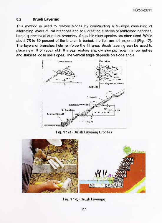
6.2 Brush Layering
This method is used to restore slopes by constructing a fill-slope consisting of
alternating layers of live branches and soil, creating a series of reinforced benches.
Large quantities of dormant branches of suitable plant species are often used. While
about 75 to 80 percent of the branch is buried, the tips are left exposed (Fig. 17).
The layers of branches help reinforce the fill area. Brush layering can be used to
place new fill or repair old fill areas, restore shallow slumps, repair narrow gullies
and stabilise loose soil slopes. The vertical angle depends on slope angle.
Cross Section Plan View
Fig. 17 (a) Brush Layering Process
Fig. 17 (b) Brush Layering
27
IRC:56-2011
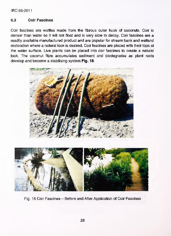
6.3 Coir Fascines
Coir fascines are wattles made from the fibrous outer husk of coconuts. Coir is
denser than water so it will not float and is very slow to decay. Coir fascines are a
readily available manufactured product and are popular for stream bank and wetland
restoration where a natural look is desired. Coir fascines are placed with their tops at
the water surface. Live plants can be placed into coir fascines to create a natural
look. The coconut fibre accumulates sediment and biodegrades as plant roots
develop and become a stabilising system Fig. 18.
Fig. 18 Coir Fascines - Before and After Application of Coir Fascines
28
IRC:56-2011
6.4 Pre-Vegetated Mats
Pre-vegetated mats are live plants grown on a movable mat of organic material.
Pre-vegetated mats are made of coir or other slowly degradable material and can
use many types of plants. They come in many sizes and materials and are moved
and installed in one piece. They are generally 1.2 m by 2.4 m in size for easy
handling. Vegetated mats are grown in nurseries for upto a year or more to provide
a good plant stand. Thin mats can be rolled up and shipped without special packing.
Thick mats are handled with heavy equipment because of their weight. Mats are
usually used in wetland or lakeshore environments, so wetland plants are the most
common.
6.5 Interplanting Rip-Rap
Rip-rap is often used to protect stream banks and lakeshores. Live cuttings can be
interplanted in rip-rap to provide additional slope stability. Root growth below the rip-
rap will improve soil strength and live vegetation will hide the rocks, presenting a
more natural look.
6.6 Staking
Staking is used extensively in bioengineering practice. Stakes can be live or dry.
Live staking is often done with willows to stabilise soil or to stake other materials in
place. Manufactured timber stakes, 0.6 to 1.0 m long, are used to secure wattles
and coir fascines. Timber stakes for upland application need to have a bias, or angle
cut, making it easier to install. For wetland or streamside applications, stakes need
straight parallel sides to prevent heaving from water pressure.
Live cuttings should be soaked in cold water for at least 24 hours before they are
used. This not only provides the cuttings with needed moisture but also improves
rooting. Live potted plants are often used. Care of live plants before and during
planting is critical for success. Live plants raised indoors need to be acclimatised to
the outdoor environment before planting.
6.7 Effectiveness of Bioengineering Techniques
Bioengineering can be effective in many stream bank, lakeshore and hill slope
erosion situations, but it will not solve all soil erosion or slope failure problems. The
29
IRC:56-2011
success of a project hinges on many factors including proper design, plant selection,
proper installation, weather conditions and outside factors like animal damage. Site
evaluation is important to determine whether there is adequate sunlight, soil type
and water quality to support vigorous plant growth. Bioengineering solutions may not
be successful in submerged areas or in geologically unstable sites. Nor are they
ideal for high stress areas with severe wave action, rapid or long-term water level
fluctuations or at locations where flow of water is very fast. The following list includes
tips that may help ensure a successful bioengineering project.
Bioengineering solutions are not to be attempted in situations where:
a) There is severe soil or water contamination
b) The stream bottom is degrading
c) Locations where human or animal traffic at the site cannot be
controlled; or
d) There is too much shade for selected plant species to thrive.
Further, it should be noted that, in case of river bank protection, while using
bioengineering techniques, water elevation is the most critical element for successful
installation. Records of normal, high and low water elevations for the site must be
available at any particular site. The seasonal changes in water elevation and how
rapidly these changes occur must also be known. Before implementing
bioengineering measures, one must be sure to fence out animals and people, if
needed. If the plants are damaged, supplemental planting may be necessary. An
awareness of flood or drought conditions that could impact installation must be
there. Severe weather will reduce seedling survival. Sometimes a combination of
various practices is found to be very effective and has been adopted at many
locations. There is a need to provide regular monitoring and maintenance, especially
in the first year, to assure adequate plant survival. There is also need to involve the
proper design professionals and botanical/agronomy experts to provide information
on hydrology, plantings and structural design. A multi-disciplinary approach will
assure success.
7 SLOPES IN COHESIONLESS SOILS
In a purely cohesionless soil, it is rather difficult to establish vegetation. Even if it
were possible, the sand grains in-between the network of root-system are most
susceptible of being 'piped our or washed out', since the distant roots can hardly
30
IRC:56-2011
afford resistance to the movement of individual grains at tine surface. Once the
movement starts, it can become progressively unconfined and is most liable to 'flow'.
The remedial treatment is therefore to provide 25 cm to 30 cm thick clayey soil (but
not heavy clays) as a blanket covering the slopes of the embankment, tamp it well
on the slopes and subsequently provide the simple vegetative treatment /'
recommended in Section 5.1. Alternatively, root mat systems like 3-D mats or'
geocells can also be used in case of cohesionless soils.
8 SLOPES IN BLACK COTTON SOILS
Invariably, there does not appear to be any need for special treatment against
erosion on black cotton soil slopes, since this type of soil promotes natural growth of
grass and other types of vegetation. The main problem seems to be the formation of
shrinkage cracks. Therefore, it is recommended that these slopes may be managed
with the simple method of providing vegetative turfing if the natural growth of grass
happens to be inadequate. Artificial watering can be resorted to if there are
economic means of procuring water, in the eventuality of the rainfall proving to be
very scanty and in the event of the work having to be carried out beyond the
monsoon season. Vetiver planting and any other suitable method can also be taken
up on these slopes.
9 SELECTION OF EROSION CONTROL METHODThe following suggestions may be generally kept in view for adopting suitable
method of erosion control for soil slopes:
a) Developing vegetation cover would be the best method to prevent
soil erosion. This may be attempted by using 'Simple Turfing
Method'. At locations where turfing is to be achieved within a short
time period, transplantation of readymade turfs can be tried.
b) Organic mulch application (either manually or by using hydroseeding)
can be adopted to aid simple vegetative turfing. By using
hydroseeding method, inaccessible and near vertical slopes can be
successfully vegetated and hydroseeding method can be used in
combination with nettings/ mats to make them even more effective.
c) At locations where simple turfing method cannot ensure vegetation
cover, natural fibre based netting can be adopted to support
vegetation growth. When the site is located in a drought prone area
and it is difficult to sustain green cover throughout the year, synthetic
geogrids can be adopted to provide long term protection.
31
IRC:56-2011
d) Where vegetation cover alone is insufficient and soil surface needs to
be protected in the absence of vegetation cover in certain patches,
root reinforcing geosynthetic systems (3-D mats or geocells) can be
used. Depending upon the duration for which protection needed
(short term - 2 to 3 years or for longer term), either natural fibre
based or polymer based 3-D mats can be adopted. For slope heights
more than 5 m, root reinforcing systems would be better suited.
e) For slopes in the waterfront having velocity of flow in excess of 3
m/sec or having wave uplift effect, having inundation or continuous
flooding for many days, slope protection system as indicated in
Section 5.11 shall be resorted to. For floodable slope with siity clay
type of soil, combination of rip-rap and geogrids may be used upto
high flood level and for the remaining slope portion geogrid may be
used. Should occasional flooding is envisaged in slope laid with
geogrid, appropriate plant species which can survive under short
term submergence shall be chosen.
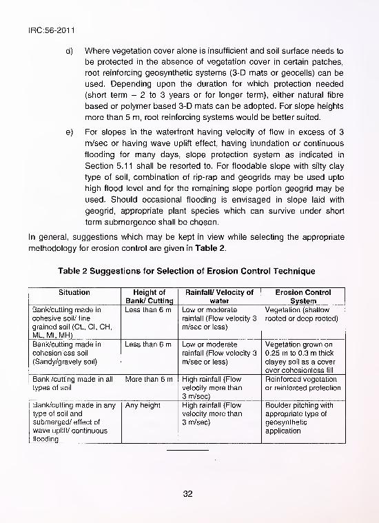
In general, suggestions which may be kept in view while selecting the appropriate
methodology for erosion control are given in Table 2.
Table 2 Suggestions for Selection of Erosion Control Technique
Situation Height of
Bank/ Cutting
Rainfall/ Velocity of
water
Erosion Control
SystemBank/cutting made in
cohesive soil/ fine
grained soil (CL, CI, CH,ML, Ml, MH)
Less than 6 m Low or moderate
rainfall (Flow velocity 3
m/sec or less)
Vegetation (shallow
rooted or deep rooted)
Bank/cutting made in
cohesionless soil
(Sandy/gravely soil)
Less than 6 m Low or moderate
rainfall (Flow velocity 3
m/sec or less)
Vegetation grown on
0.25 m to 0.3 m thick
clayey soil as a cover
over cohesionless fill
Bank /cutting made in all
types of soil
More than 6 m High rainfall (Flow
velocity more than
3 m/sec)
Reinforced vegetation
or reinforced protection
Bank/cutting made in anytype of soil andsubmerged/ effect of
wave uplift/ continuous
flooding
Any height High rainfall (Flow
velocity more than
3 m/sec)
Boulder pitching with
appropriate type of
geosynthetic
application
32
IRC:56-2011
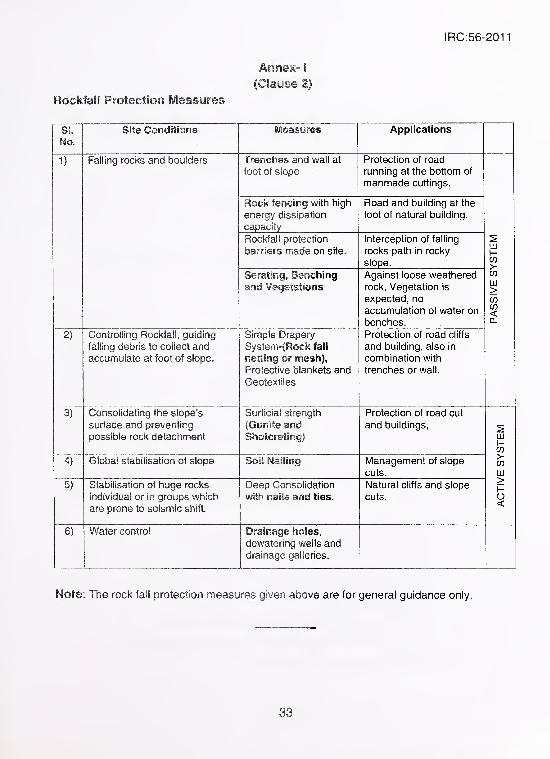
Annex- i
(Clause 2)
Rockfail Protectiori IVIeasures
SLNo.
Site Conditions Wieasyres Applications
1) Falling rocks and boulders Trenches and wall at
foot of slope
Protection of road
running at the bottom of
manmade cuttings.
Rock fencing with high
energy dissipation
capacity
Road and building at the
foot of natural building.
Rockfail protection
barriers made on site.
Interception of falling
rocks path in rocky
slope.
/STEM
Serating, Benchingand Vegetations
Against loose weathered
rock, Vegetation is
expected, no
accumulation of water on
benches.
PASSIVE
S'
2) Controlling Rockfail, guiding
falling debris to collect andaccumulate at foot of slope.
Simple Drapery
System-(R0ck fall
netting or mesh),
Protective blankets and
Geotextiles
Protection of road cliffs
and building, also in
combination with
trenches or wall.
3) Consolidating the slope's
surface and preventing
possible rock detachment
Surficial strength
(Gonite andShotcretirsg)
Protection of road cut
and buildings,
STEM
4) Global stabilisation of slope Soil Nailing Management of slope
cuts.
>-
UJ
5) Stabilisation of huge rocks
individual or in groups which
are prone to seismic shift.
Deep Consolidation
with nails and ties.
Natural cliffs and slope
cuts.ACTIV
6) Water control Drainage holes,
dewatering wells anddrainage galleries.
Mote: The rock fall protection measures given above are for general guidance only.
33
IRC:56-2011
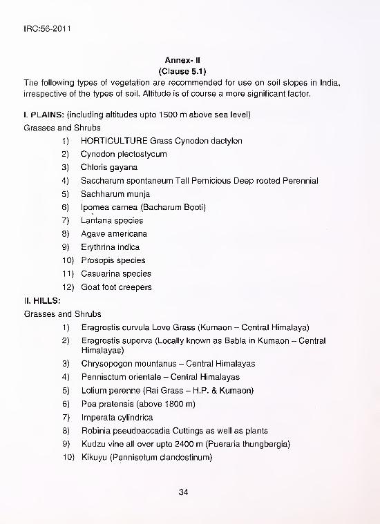
Annex- II
(Clause 5.1)
The following types of vegetation are recommended for use on soil slopes in India,
irrespective of the types of soil. Altitude is of course a more significant factor.
I. PLAINS: (including altitudes upto 1500 m above sea level)
Grasses and Shrubs
1 ) HORTICULTURE Grass Cynodon dactylon
2) Cynodon plectostycum
3) Chloris gayana
4) Saccharum spontaneum Tall Pernicious Deep rooted Perennial
5) Sachharum munja
6) Ipomea carnea (Bacharum Booti)
7) Lantana species
8) Agave americana
9) Erythrina indica
1 0) Prosopis species
11) Casuarina species
1 2) Goat foot creepers
II. HILLS:
Grasses and Shrubs
1) Eragrostis curvula Love Grass (Kumaon - Central Himalaya)
2) Eragrostis superva (Locally known as Babia in Kumaon - Central
Himalayas)
3) Chrysopogon mountanus - Central Himalayas
4) Pennisctum orientale - Central Himalayas
5) Lolium perenne (Rai Grass - H.P. & Kumaon)
6) Poa pratensis (above 1800 m)
7) Imperata cylindrica
8) Robinia pseudoaccadia Cuttings as well as plants
9) Kudzu vine all over upto 2400 m (Pueraria thungbergia)
10) Kikuyu (Pennisetum clandestinum)
34
IRC:56-2011
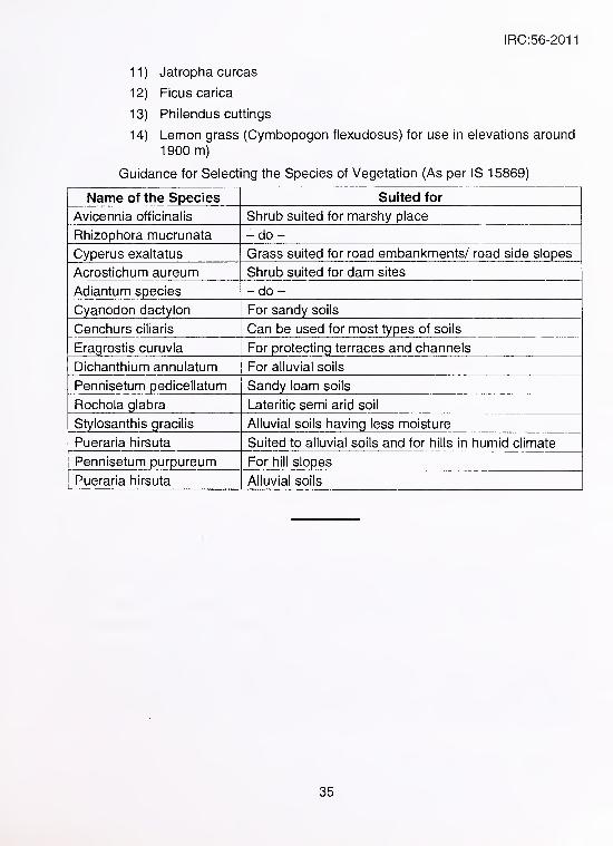
11) Jatropha curcas
12) Ficus carica
13) Philendus cuttings
14) Lemon grass (Cymbopogon flexudosus) for use in elevations around
1900 m)
Guidance for Selecting the Species of Vegetation (As per IS 15869)
Name of the Species Suited for
Avicennia officinalis Shrub suited for marshy place
Rhizophora mucrunata -do-Cyperus exaltatus Grass suited for road embankments/ road side slopes
Acrostichum aureum Shrub suited for dam sites
Adiantum species -do-Cyanodon dactylon For sandy soils
Cenchurs ciliaris Can be used for most types of soils
Eragrostis curuvia For protecting terraces and channels
Dichanthium annulatum For alluvial soils
Pennisetum pedicellatum Sandy loam soils
Rochola glabra Lateritic semi arid soil
Stylosanthis gracilis Alluvial soils having less moisture
Pueraria hirsuta Suited to alluvial soils and for hills in humid climate
Pennisetum purpureum For hill slopes
Pueraria hirsuta Alluvial soils
35
IRC:56-2011
AooeX" ill
(ClaoseSJI)
Slope Erosion Protection Using Gabions and Mattresses
With mechanically woven double twisted steel wire mesh products such as Gabions,
it is possible to construct flexible structures that effectively sustain the eroding slope
and also preserve their natural look, thus providing eco~compatible solutions. The
hexagonal shape of the mesh provides a better distribution of the working tensions
along the wires that form the mesh. Double twist avoids spreading of the damage
caused by the accidental breaking of any wire. The steel wire shall either be heavily
zinc coated or zinc plus PVC coated to provide adequate protection against
corrosion. Steel wire mesh Gabions and Revet Mattresses should conform to ASTMspecification A 975 or ISO 7989 and ISO 22034. Gabion baskets are also made
using welding process. While such welded wire mesh gabions do not possess
flexibility as compared to woven wire mesh gabions, welded wire mesh gabions can
be made to any convenient size and also their protective coating thickness can be
easily varied.
The products of Mechanically Woven Double twisted hexagonal steel wire meshes
that can be used for protecting the slope from erosion are
a) Gabions
b) Gabion mattresses (revet mattresses)
Gabions
Gabions are rectangular wire mesh baskets filled with rock at the project site to form
flexible, permeable, monolithic structures. They are made of hexagonal shaped
double twisted steel woven wire mesh, with high mechanical characteristics. The
gabion is divided into cells by means of diaphragms positioned at approximately 1 mcentres. The steel wire used in the manufacture of the gabion shall be coated with
zinc or zinc and polymeric coated for protection from corrosion. In order to reinforce
the structure, all mesh panel edges are selvedged with a wire having a greater
diameter. With 30 per cent voids, gabion structures offer free drainage providing
higher bank stability when used for river bank protection.
36
IRC:56-2011
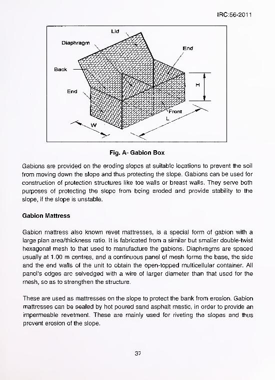
Fig. A- Gabion Box
Gabions are provided on the eroding slopes at suitable locations to prevent the soil
from moving down the slope and thus protecting the slope. Gabions can be used for
construction of protection structures like toe walls or breast walls. They serve both
purposes of protecting the slope from being eroded and provide stability to the
slope, if the slope is unstable.
Gabion Mattress
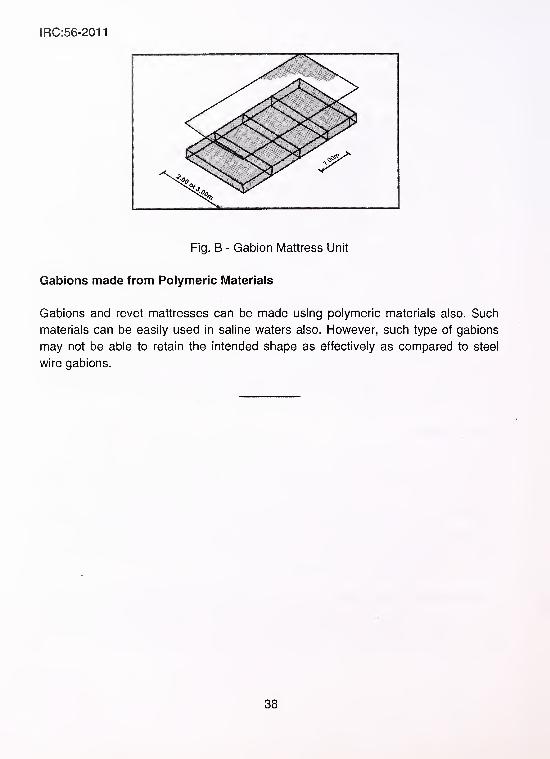
Gabion mattress also known revet mattresses, is a special form of gabion with a
large plan area/thickness ratio. It is fabricated from a similar but smaller double-twist
hexagonal mesh to that used to manufacture the gabions. Diaphragms are spaced
usually at 1 .00 m centres, and a continuous panel of mesh forms the base, the side
and the end walls of the unit to obtain the open-topped multicellular container. All
panel's edges are selvedged with a wire of larger diameter than that used for the
mesh, so as to strengthen the structure.
These are used as mattresses on the slope to protect the bank from erosion. Gabion
mattresses can be sealed by hot poured sand asphalt mastic, in order to provide an
impermeable revetment. These are mainly used for riveting the slopes and thus
prevent erosion of the slope.
3^
IRC:56-2011
Fig. B - Gabion Mattress Unit
Gabions made from Polymeric IVIaterials
Gabions and revet mattresses can be made using polymeric materials also. Such
materials can be easily used in saline waters also. However, such type of gabions
may not be able to retain the intended shape as effectively as compared to steel
wire gabions.
38

(The Official amendments to this document would be published bythe IRC in its periodical, 'Indian Highways' which shall be
considered as effective and as part of the code/guidelines/manual,
etc. from the date specified therein)