recommended practices for construction of - superior...
TRANSCRIPT
Recommended Practicesfor Construction ofResidential MasonryBasements in MinnesotaFifth Edition
Includes cold weather masonry construction guidelinesand recommended radon guidelines
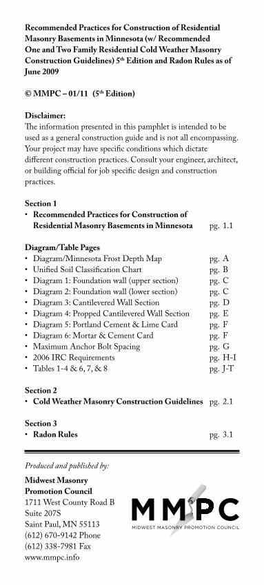
Recommended Practices for Construction of Residential Masonry Basements in Minnesota (w/ Recommended One and Two Family Residential Cold Weather Masonry Construction Guidelines) 5th Edition and Radon Rules as of June 2009
© MMPC – 01/11 (5th Edition)
Disclaimer:The information presented in this pamphlet is intended to be used as a general construction guide and is not all encompassing. Your project may have specific conditions which dictate different construction practices. Consult your engineer, architect, or building official for job specific design and construction practices.
Section 1• Recommended Practices for Construction of Residential Masonry Basements in Minnesota pg. 1.1
Diagram/Table Pages • Diagram/MinnesotaFrostDepthMap pg. A• UnifiedSoilClassificationChart pg. B• Diagram1:Foundationwall(uppersection) pg. C• Diagram2:Foundationwall(lowersection) pg. C• Diagram3:CantileveredWallSection pg. D• Diagram4:ProppedCantileveredWallSection pg. E• Diagram5:PortlandCement&LimeCard pg. F• Diagram6:Mortar&CementCard pg. F• MaximumAnchorBoltSpacing pg. G• 2006IRCRequirements pg. H-I• Tables1-4&6,7,&8 pg. J-T
Section 2• Cold Weather Masonry Construction Guidelines pg. 2.1
Section 3• Radon Rules pg. 3.1
Produced and published by:
Midwest MasonryPromotion Council1711WestCountyRoadBSuite207SSaintPaul,MN55113(612)670-9142Phone(612)338-7981Faxwww.mmpc.info
1.1
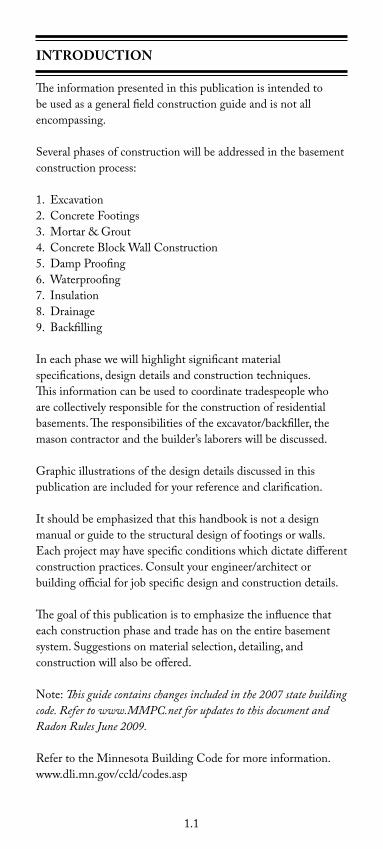
INTRODUCTION
The information presented in this publication is intended to be used as a general field construction guide and is not all encompassing.
Severalphasesofconstructionwillbeaddressedinthebasementconstructionprocess:
1.Excavation2.ConcreteFootings3.Mortar&Grout4.ConcreteBlockWallConstruction5.DampProofing6.Waterproofing7.Insulation8.Drainage9.Backfilling
Ineachphasewewillhighlightsignificantmaterialspecifications,designdetailsandconstructiontechniques.This information can be used to coordinate tradespeople who are collectively responsible for the construction of residential basements.Theresponsibilitiesoftheexcavator/backfiller,themason contractor and the builder’s laborers will be discussed.
Graphicillustrationsofthedesigndetailsdiscussedinthispublication are included for your reference and clarification.
Itshouldbeemphasizedthatthishandbookisnotadesignmanual or guide to the structural design of footings or walls. Eachprojectmayhavespecificconditionswhichdictatedifferentconstructionpractices.Consultyourengineer/architectorbuilding official for job specific design and construction details.
Thegoalofthispublicationistoemphasizetheinfluencethateach construction phase and trade has on the entire basement system.Suggestionsonmaterialselection,detailing,andconstruction will also be offered.
Note:This guide contains changes included in the 2007 state building code. Refer to www.MMPC.net for updates to this document and Radon Rules June 2009.
RefertotheMinnesotaBuildingCodeformoreinformation.www.dli.mn.gov/ccld/codes.asp
1.2
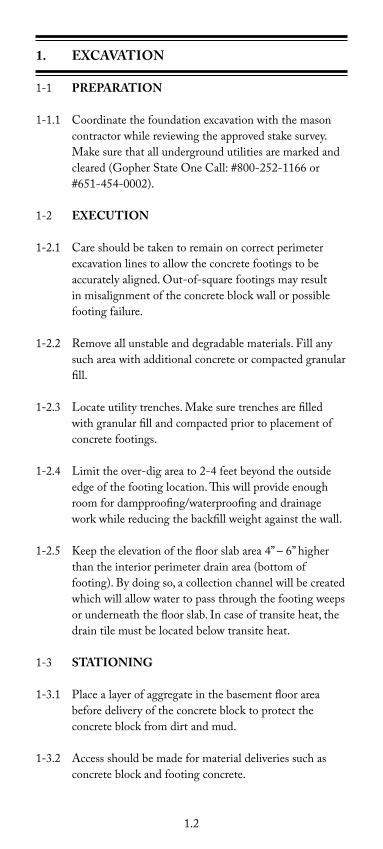
1. ExCavaTION
1-1 PREPaRaTION
1-1.1 Coordinatethefoundationexcavationwiththemasoncontractorwhilereviewingtheapprovedstakesurvey.Makesurethatallundergroundutilitiesaremarkedandcleared(GopherStateOneCall:#800-252-1166or#651-454-0002).
1-2 ExECUTION
1-2.1 Careshouldbetakentoremainoncorrectperimeterexcavationlinestoallowtheconcretefootingstobeaccuratelyaligned.Out-of-squarefootingsmayresultinmisalignmentoftheconcreteblockwallorpossiblefooting failure.
1-2.2 Removeallunstableanddegradablematerials.Fillanysuch area with additional concrete or compacted granular fill.
1-2.3 Locateutilitytrenches.Makesuretrenchesarefilledwith granular fill and compacted prior to placement of concrete footings.
1-2.4 Limittheover-digareato2-4feetbeyondtheoutsideedge of the footing location. This will provide enough roomfordampproofing/waterproofinganddrainageworkwhilereducingthebackfillweightagainstthewall.
1-2.5 Keeptheelevationofthefloorslabarea4”–6”higherthantheinteriorperimeterdrainarea(bottomoffooting).Bydoingso,acollectionchannelwillbecreatedwhich will allow water to pass through the footing weeps orunderneaththefloorslab.Incaseoftransiteheat,thedrain tile must be located below transite heat.
1-3 STaTIONING
1-3.1 Placealayerofaggregateinthebasementfloorareabeforedeliveryoftheconcreteblocktoprotecttheconcreteblockfromdirtandmud.
1-3.2 Accessshouldbemadeformaterialdeliveriessuchasconcreteblockandfootingconcrete.
1.3
2. CONCRETE FOOTINGS
2-1 DESIGN
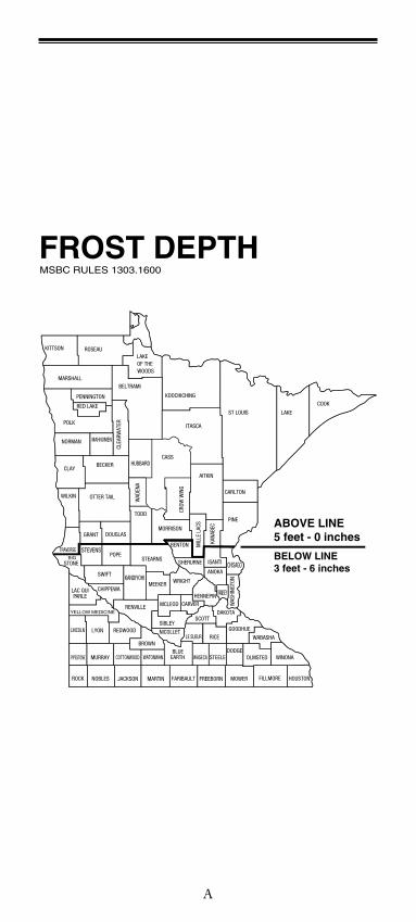
2-1.1 Concrete footings must bear on soil which is beneath themaximumfrostpenetrationdepth.Refertothe[AppendixpageAfortheMinnesotaFrostDepthMap.]
2-1.2 Refer to IRC Table 403.1 for minimum footing width. Formostconditionstypicalfootingsizeis8”highby16”or20”wide.Footingdimensionrequirementscanvarydependingonsoilandloadconditions.Footingprojectionsshouldbeatleast2inchesbeyondthefoundation wall.
2-1.3 Footingconcreteshouldhaveaminimumcompressivestrengthof2,500p.s.i.Specifically,callforthestrengthofconcreteyourprojectrequires.ReferenceAppendixTables6,7,&8onpagesQ-Tofthisbooklet.CantileverFoundationsrequireaminimumcompressivestrengthof3,000p.s.i.
2-1.4 Althoughnotalwaysmandatory,two½”minimumreinforcingrods(rebar)placed3inchesfromthebottom of the footing running parallel to the wall, are recommendedtohelpavoidcrackingand/ordifferentialsettlement of the footing.
2-1.5 Footingsshouldbecontinuous.Footingheightchangesare typically accomplished by the use of vertical bulkheadsreinforcedwithtwo½”(minimum)reinforcingrods.
2-1.6 Dowelsinthefootingsarenottypicallyrequiredbycodeforresidentialconcreteblockwalls.Exception:SomeCantileverWallsconditionsmayrequiredowels.SeeAppendixTables6,7&8onpageQ-Tofthisbooklet.Referencetofootnoteh.
2-2 CONSTRUCTION
2-2.1 The footings should be formed and poured as soon as possibleaftertheexcavationiscompleted.Thiswillavoidexcessivemoisture(rain,snow)fromsaturatingthegroundandpossiblydestabilizingthesoil.Ifthesoildoesbecome“soft”,theareashouldbescrapedofforre-dug.Takepropercaretoensurethatminimumelevationandclearance from the water table is attained.
1.4
2-3 Donotpourfootingsoverunstablematerialsuchastreeroots,constructiondebris,softspots,ice,etc.Removeallunstable material and fill resulting voids with compacted granular fill or concrete before forming or pouring footings.
2-4 Footingalignmentmustbeaccuratesothatthecenterlineoftheconcreteblockwallstaysascloseaspossibletothe center line of the footing.
2-5 Cautionshouldbetakenwhenaddingwatertoconcreteinthefield.Excessivewatercanseverelyreducethestrength of concrete.
2-6 Donottrowelfootingsurfaces.Aslightlyroughfootingsurface helps assure a good bond between the first course ofconcreteblockandthefooting.
3. MORTaR & GROUT
3-1 MORTaR •PreblendedMortar:AdrymixtureofPortland
Cement,HydratedLimeandOvenDriedMasonrySandformulatedandblendedinamanufacturingfacility to meet the property specification requirementsofASTMC270.
•FieldMixedMortars:AmixtureofPortlandCement,HydratedLimeandMasonrySandorMasonry/MortarCementandMasonrySandmixedatthejobsitetotheproportionspecificationrequirementsofASTMC270.
3-1.1 AllmortarusedinfoundationworkshouldbeTypeSorTypeM.RefertoMCMAMortarCardsonpageF.
3-1.2 Mortarmaybepre-blendedorproportionedon-siteandshouldmeetASTMC270.
3-1.3 Watershouldbepotableandshouldnotexceed160˚F(71˚C).
3-1.4 The preparation of mortar and grout in the field is an integralpartoftheconstructionofmasonrywalls.Toprovide consistent batching, materials used to charge the mixermustbecontrolled.
1.5
3-1.5 Pre-Blended Mortar3-1.5.1 Proper Mixing Procedures
Duetothefactthattherearemanytypesofmixers,thisprocedurereferstomixingmasonrymortarsinastandardmechanicalmixer.
1. Add2/3ofrequiredwatertoanempty,cleanmixerandstartthemixer.
2. AddPreblendedMortar,PreblendedColoredMortarorGrouttothemixer.
3. Ifnecessary,addremainingwatertothemixeruntilproper consistency is achieved.
4. Mixbetween3and10minutes.
Note: Completely empty mortar content into wheelbarrow or container.
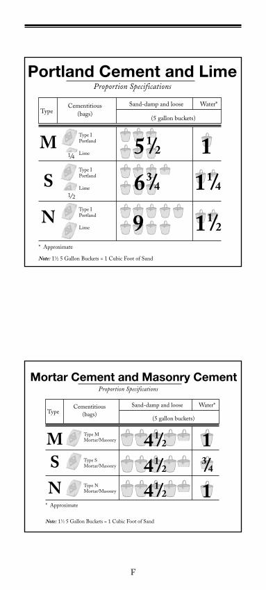
3-1.6 Proportioning On-Site Mortar3-1.6.1 The Mortar Cement and Masonry Cement table and
the Portland Cement and LimetableontheappendixpageFofthisbookreferencetypicalmortartypesandproportioningusingASTMC270.
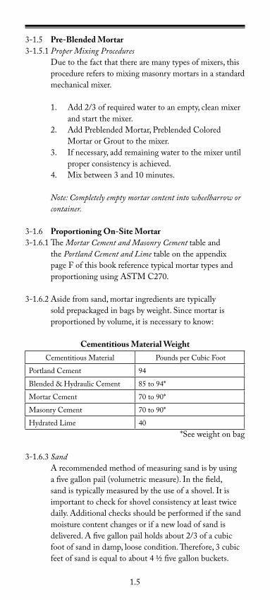
3-1.6.2Asidefromsand,mortaringredientsaretypicallysoldprepackagedinbagsbyweight.Sincemortarisproportionedbyvolume,itisnecessarytoknow:
Cementitious Material WeightCementitiousMaterial PoundsperCubicFoot
PortlandCement 94
Blended&HydraulicCement 85to94*
MortarCement 70to90*
MasonryCement 70to90*
HydratedLime 40*Seeweightonbag
3-1.6.3 SandArecommendedmethodofmeasuringsandisbyusingafivegallonpail(volumetricmeasure).Inthefield,sandistypicallymeasuredbytheuseofashovel.Itisimportanttocheckforshovelconsistencyatleasttwicedaily.Additionalchecksshouldbeperformedifthesandmoisture content changes or if a new load of sand is delivered.Afivegallonpailholdsabout2/3ofacubicfootofsandindamp,loosecondition.Therefore,3cubicfeetofsandisequaltoabout4½fivegallonbuckets.
1.6
3-1.6.4Proper Mixing ProceduresDuetothefactthattherearemanytypesofmixers,thisprocedurereferstomixingmasonrymortarsinamechanicalmixer.
1. Add2/3ofrequiredwatertoanempty,cleanmixerandstartthemixer.
2. Add½theamountofsandrequiredtothemixer3. Addanycoloringpigmentstothemixer(where
applicable).4. Addlimetothemixer(ifapplicable).5. Addcementtothemixer:(Cement,Masonry
Cement,orMortarCement).6. Addremainingsandtothemixer.7. Ifnecessary,addremainingwatertothemixeruntil
proper consistency is achieved.8. Mixbetween3minutes(minimum)*and15
minutes(maximum)afteraddingthelastofthewaterinstep(7)above.
(*Additionalmixingtimeuptotenminutesmayberequiredwhenusingmortarmaterialscontainingovendriedsand.)Note: Completely empty mortar contents into wheelbarrow or container.
3-1.6.5 Retempering Freshmortarshouldbepreparedattherateitisusedtomaintainworkabilityandconsistencyonthejobsite.Mortarthathasbeenmixedbutnotusedimmediatelywillexperiencestiffeningastheproductdriesout.Toreduce this evaporation effect, you may wet the mortar board and cover the mortar in the tub or wheelbarrow. Ifnecessarytorestoreworkability,mortarmayberetemperedbyaddingsmallamountsofwater.Ingeneral,mortarmayberetemperedupto2½hoursafteroriginalmixing.Mortarover2½hoursoldshouldbediscarded.
3-2 GROUT •PreblendedGrout:AdrymixtureofPortland
Cement,OvenDriedMasonrySandandAggregateformulated and blended in a manufacturing facility tomeettherequirementsofASTMC476.
3-2.1 Groutmaybepre-blended,proportionedon-site,ordeliveredbyready-mixtruckandshouldmeetASTMC476.
1.7
3-2.2 Pre-Blended Grout3-2.2.1Proper Mixing Procedures
Duetothefactthattherearemanytypesofmixers,thisprocedurereferstomixingmasonrymortarsinastandardmechanicalmixer.
1. Add2/3ofrequiredwatertoanempty,cleanmixerandstartthemixer.
2. AddGrouttothemixer.3. Ifnecessary,addremainingwatertothemixeruntil
proper consistency is achieved.4. Mixbetween3and10minutes.
Note: Completely empty grout contents into wheelbarrow or container.
3-2.3 Proportioned On-Site Grout3-2.3.1Proportions for Fine Grout Use1partcementmixedwith2¼to3partssand.
3-2.3.2Proportions for Coarse Grout Use1partcementmixedwith2¼partssandand1to2
parts3/8"aggregate.
3-2.3.3 Proper Mixing ProceduresDuetothefactthattherearemanytypesofmixers,thisprocedurereferstomixingmasonrymortarsinamechanicalmixer.
1. Add2/3ofrequiredwatertoanempty,cleanmixerandstartthemixer.
2. Addsandand3/8”aggregatetothemixerandmixfor30seconds.
3. Addcementtothemixer.4. Ifnecessary,addremainingadmixturesandwaterto
themixeruntilproperconsistencyisachieved.5. Mixbetween3minutes(minimum)*and15
minutes(maximum)afteraddingthelastofthewaterinstep(4)above.
3-3 PROTECTING MaSONRy MaTERIalS Bagged Materials
• Storeonpalletsofftheground• Completelycovertoprotectfromrainorsnow• Stockpileonoppositesideofmixerfromwater
supply and sand
1.8
Sand (On-site proportioning)• Placestockpileontarptoprotectfrom
contamination from below• Coverwithtarpwhennotinusetomaintain
consistent moisture content and avoid contaminants• Storeonoppositesideofmixerfrombagged
materials• Storedifferentaggregatesseparatelytoavoidcross
contaminationofstockpiles
Concrete Masonry Units (CMU or Block)• Coverstockpilestokeepdryandclean.• Storeawayfrommixingsiteand/orcement
materials
3-4 HOT WEaTHER MORTaR aND GROUT ISSUESHotweatherconstructionoccurswhentheambienttemperatureexceeds90°Fwithawindvelocityofgreaterthan8mph.
Potential problems of hot weather construction:• Rapidlossofworkability• Rapidevaporationofwaterrequiredforcement
hydration and curing.
Procedures to follow when working with masonry in hot weather:
• Keepmortar,groutandCMU’sascoolaspracticalusingtechniquessuchasplacingmaterialsintheshadeandusingcoolwaterwhenmixing.
• Keepanysurfacethatcomesincontactwiththemortarorgroutsuchasmixers,wheelbarrows,shovels, mortar boards, trowels damp.
• Limittheamountofmortarthatisspreadonthebedjointsto4feetaheadoftheCMU.PlaceCMUwithin one minute of spreading the mortar.
• Inhot,dryandwindyweather,lightlyfogormistthe finished wall, if possible.
3-5 PROTECTION OF UNFINISHED WallSAllunfinishedwallsshouldbecoveredwithweather-resistant material, on both sides, from the top of thewalldowntothefootingsfor48hoursafterconstruction.Wherenecessary,installwindbreakswhenwindvelocityexceeds15mph(6.7m/s).
1.9
4. CONCRETE BlOCK Wall CONSTRUCTION
4-1 MaTERIalS
4-1.1 Concreteblockusedforresidentialfoundationsshould complywithASTMC90.Propercareshouldbetakento
maintaindryconcreteblockpriortobuildingthewall.
4-2 DESIGN
4-2.1 Priortolayingthefirstcourseofconcreteblock,reviewthe layout, dimensions and locations of all wall openings. Determineifshorterconcreteblocklengths(cuts)arerequired.Startingyourwallwiththecuts(ifbondwillallow)orplacingcutsoneithersideofwallopeningswillmakeforamoreattractivewall.
4-2.2 Structuralfoundationblocksmustbeaminimum6"width.Whereawallchangeswidth,thetopcourseofthewiderblockshouldbeeitherasolidunitorgroutedsolid.
4-2.3 Minimumverticalreinforcementbarsizeandspacingfor8",10"and12"nominalwallthicknessshouldcomplywithTablesR404.1.1(1),R404.1.1(2),R4041.1(3)orR404.1.1(4)ofthe2006InternationalResidentialCode™(IRC).RefertopagesJ-Pfortables1-4.Alternatereinforcingbarsizesandspacinghavinganequivalentcross-sectionalareaofreinforcementperlineal foot of wall should be permitted provided the spacingofthereinforcementdoesnotexceed72inches.SeeAppendixforTables2,3,and4onpagesK-Pwithalternatebarsizes,spacingandsoilclasses.
Permanentlysupportedfoundationwallswhicharesupportedatthetopbyfloormembersshallhavereinforcing bars positioned toward the inside face shell oftheconcreteblockcore.Bypositioningthereinforcingbars in this manner, the walls will have greater resistance to lateral earth pressures. The distance from the face of the soil side of the wall to the center of vertical reinforcement should be the minimum specified at each table:8"CMU=5",10"CMU=6.75"and12"CMU=8.75".SoilclassesareinaccordancewiththeUnifiedSoilClassificationSystemreferencedinIRCTableR405.1onpageB.
1.10
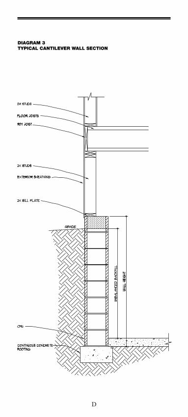
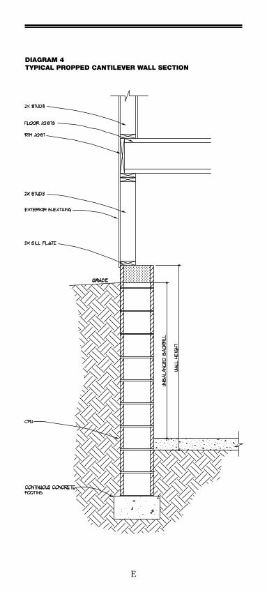
4-2.4 Foundationwallswhicharenotpermanentlysupportedatthetopbyfloormembersareconsidered“cantileveredwalls.”RefertoFootnoteConTables6,7,and8onAppendixpagesQ-Tforwallreinforcementrequirementsfor8",10"and12"walls.Notefootnotes(g)and(h)forconditionswhichmayrequire“proppedcantileveredwalls”(seediagram4onpageE)ormayrequiredowelingtothefootings.SpecialDesignisalwaysanalternativetothetables.AnotheralternativeistobuildthewallfullheighttofloorbearingandreinforcetoTables2,3or4onpagesK-P.Notethatshortwallstypicaltofrostfootingorlook-outfoundationsdonotrequirereinforcement.
4-2.5 The wood sill plate should be anchored to the foundation withanchorboltsspacedamaximumof6feetoncenter.SeeAppendixpageGformaximumboltspacing.Whenverticalreinforcingisrequired,theanchorboltsorstrapsshould align with the reinforcing. Note: Not all bolts or straps need to be placed at corefills. Anchorboltsshouldalsobelocatedwithin12inchesfromtheendsofeachplatesection. Note: Where longer walls require multiple sill plate sections, consider installing an additional bolt at anticipated joint locations.Boltsshouldbeatleast½inchindiameterandshouldextendaminimumof7inchesintomasonryor concrete. anchor Bolts require a 2" diameter by 0.125" galvanized thick washer counter sunk 0.25" into top of sill plate. Foundation anchor straps may be used when spaced as required to provide equivalent anchorage to 1/2 –inch diameter (12.7 mm) anchor bolts. When vertical reinforcing is required by other sections of this code, the foundation anchor straps should align with the reinforcing.
4-3 CONSTRUCTION
4-3.1 The top of the footing must be clean, free of dirt, mud, iceoranymaterialwhichmightweakenthebondbetween the mortar and footing.
4-3.2 Layfirstcourseofconcreteblockonthecenterlineofthefooting.Allfaceshellsoftheconcreteblockshouldbesetinmortar.Wherethewallistobegrouted,mortarshould be placed so it does not severely project into the corestobegroutedwhichwillpermitthegrouttomakefull contact with the footing.
4-3.3 Layconcreteblockinarunningbondwitha3/8"mortarjointcoveringthehorizontalandverticalfaceshells.
1.11
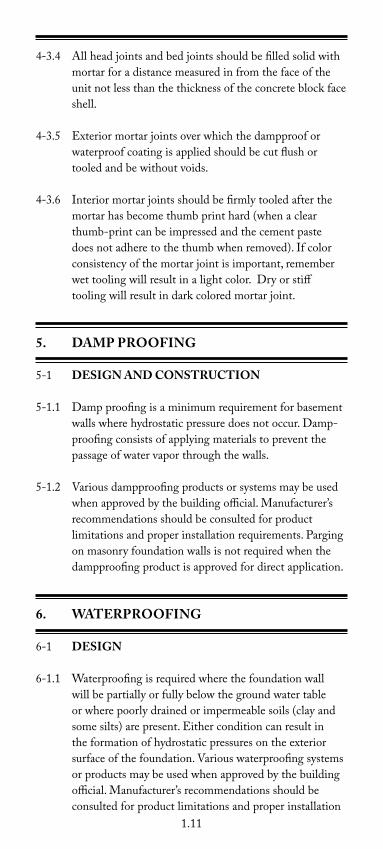
4-3.4 Allheadjointsandbedjointsshouldbefilledsolidwithmortar for a distance measured in from the face of the unitnotlessthanthethicknessoftheconcreteblockfaceshell.
4-3.5 Exteriormortarjointsoverwhichthedampprooforwaterproofcoatingisappliedshouldbecutflushortooled and be without voids.
4-3.6 Interiormortarjointsshouldbefirmlytooledafterthemortarhasbecomethumbprinthard(whenaclearthumb-printcanbeimpressedandthecementpastedoesnotadheretothethumbwhenremoved).Ifcolorconsistency of the mortar joint is important, remember wettoolingwillresultinalightcolor.Dryorstifftoolingwillresultindarkcoloredmortarjoint.
5. DaMP PROOFING
5-1 DESIGN aND CONSTRUCTION
5-1.1 Dampproofingisaminimumrequirementforbasementwallswherehydrostaticpressuredoesnotoccur.Damp-proofing consists of applying materials to prevent the passage of water vapor through the walls.
5-1.2 Various dampproofing products or systems may be used whenapprovedbythebuildingofficial.Manufacturer’srecommendations should be consulted for product limitationsandproperinstallationrequirements.Pargingonmasonryfoundationwallsisnotrequiredwhenthedampproofing product is approved for direct application.
6. WaTERPROOFING
6-1 DESIGN
6-1.1 Waterproofingisrequiredwherethefoundationwallwill be partially or fully below the ground water table orwherepoorlydrainedorimpermeablesoils(clayandsomesilts)arepresent.Eitherconditioncanresultintheformationofhydrostaticpressuresontheexteriorsurface of the foundation. Various waterproofing systems or products may be used when approved by the building official.Manufacturer’srecommendationsshouldbeconsulted for product limitations and proper installation
1.12
requirements.
6-1.2 Areasofthebasementwallwhereporch,garage,fireplace or other walls intersect should be waterproofed. Contact the product manufacturer or distributor for specific recommendations.
6-2 CONSTRUCTION
6-2.1 Applywaterproofcoatingtoconcreteblockwallsthatareclean, free of dirt, mud, ice or any material which might reduce the bond between the coating and the concrete blocksurface.
6-2.2 Coverthebaseintersectionoftheexteriorconcreteblockwall and the concrete footing surface.
6-2.3 Mostcoatingsrequiremodifiedmixingandapplicationprocedureswhentemperaturesdropbelow20˚F.Contact the coating manufacturer or distributor for specific recommendations.
7. INSUlaTION
7-1 DESIGN aND CONSTRUCTION
7-1.1 Allfoundationwallsshouldhaveexterior,integralorinteriorinsulationconformingtotherequirementsoftheMinnesotaEnergyCode.RefertotheMinnesotaEnergyCodeforspecificrequirements.
7-1.2 Integralinsulationincludesplasticfoamandrigidpolystyreneinserts.Rigidpolystyreneinserts,designedto be continuous, allow for grout and reinforcing in the insulatedcores.ToverifysystemR-values,referencetheNationalConcreteMasonryAssociation“NCMAConcreteMasonryR-ValueEvaluation.”
8. DRaINaGE
8-1 DESIGN aND CONSTRUCTION
8-1.1 Therearetwopurposesofadrainagesystem:
1. Relievethewallsandfloorslabofhydrostaticpressure by drawing down subsurface water to a
1.13
levelwhichisbelowthefloorslab.
2. Collectanddrainawaywaterthatseepsdownthroughthebackfillfromrainfall,snowmeltandroofrun-off.
8-1.2 Drainsshouldbeprovidedaroundmasonryfoundationsthat retain earth and enclose habitable or usable spaces locatedbelowgrade.Drainagetiles,gravelorcrushedstone drains, perforated pipe or other approved systems or materials should be installed at or below the area to be protected and should discharge by gravity or mechanical meansintoanapproveddrainagesystem.Gravelorcrushedstonedrainsshouldextendatleast1footbeyondtheoutsideedgeofthefootingand6inchesabovethetop of the footing and be covered with an approved filter membrane material . The top of open joints of drain tiles should be protected with strips of building paper, and the drainage tiles or perforated pipe should be placed on a minimumof2inchesofwashedgravelorcrushedrockatleastonesievesizelargerthatthetilejointopeningorperforationandcoveredwithnotlessthat6inchesofthesame material. Exception: A drainage system is not required when the foundation is installed on well-drained ground or sand-gravel mixture soil is according to the Unified Soil Classification System, Group I Soils, as detailed in Table-IRC R405.1 on page B.
9. BaCKFIllING
9-1 PREPaRaTION
9-1.1 Donotplacebackfillmaterialbeforeconcreteblockwallshavebeenproperlycuredandbracedorthesubfloorsystem is in place.
9-1.2 Aminimumwoodbracingsystemissuggestedtoconsistof4"x4"beams,oneplacedverticallyagainstthewallandtheothersetata45degreeangleagainsttheverticalatthe7thor8thconcreteblockcourseona12coursewall,securedtotheverticalwitha2"x4"tieandanchoredbydriving2"x6"stakesatleast12"intotheground.Ifthe4"x4"inclinedbraceislongerthan8',anadditional2"x4"braceshouldbesecuredtothebottomoftheverticalbraceandnailedintotheinclinedbrace.Ifusinga mechanical bracing system, follow manufacturer’s recommendations. NOTE:Bracingshouldremainuntil
1.14
subfloorsystemisinplace.
9-1.3 Bracingshouldbepositionedatamaximumof8'on center with offsets braced at one side of all inside corners,
preferably, and where possible brace walls at corefill locations.
9-1.4 Backfillonlyafterthewaterproofinganddrainagesystems is in place.
9-2 ExECUTION
9-2.1 Backfillingshouldtakeplaceinseveralliftsusingmaterialwhichisfreeoflargestones,frozenearth,organic materials or construction debris.
9-2.2 Caremustbetakennottodamagethedrainagesystem,waterproofcoatingorexteriorinsulationduringbackfilling.
9-2.3 Donotbackfillwithwatersaturateddirt,soil,orothermaterials(especiallysoilswithhighclaycontents)orplacebackfillwhereanyappreciableamountofwaterisstanding.Wetmaterialsmaycreateexcessivehydrostaticpressure and could lead to wall failure.
9-2.4 Avoidsubjectingthewallstohighimpactloadslikeearthsliding down a steep slope or boulders rolling into the wall.
9-2.5 Do not operate equipment over the backfill during the backfilling operation or after construction operations. Equipment should never be operated within 3 feet of any basement wall system. Compaction of backfill near the structure must not be done with heavy equipment.
9-2.6 Donotoperateheavyequipmentataperpendicularor90°angletothewallwhenbackfilling.Operatingequipmentata45°reducespressureagainstthewall.
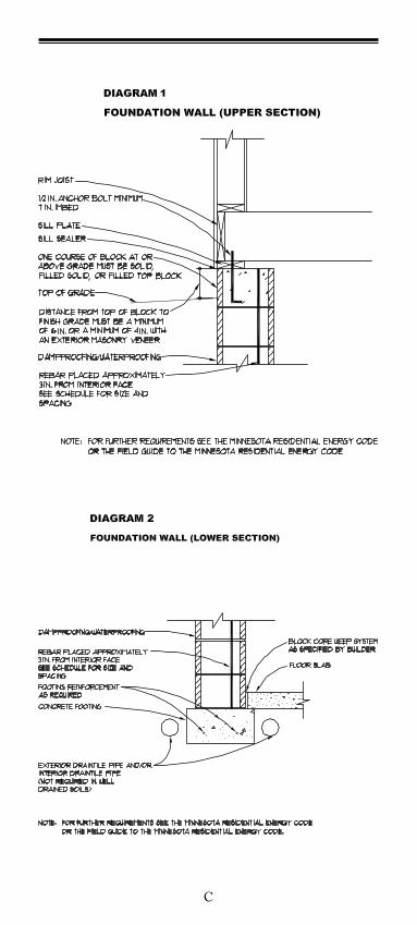
9-2.7 Masonryfoundationwallsshouldextendabovefinishedgradeaminimumof6inches.ReferenceIRCR404.1.6.Seediagram1onpageC.
9-2.8 Backfillaroundthefoundationshouldbecoveredwitha low permeability soil sloping away from the wall a minimumof6inchesinthefirst10’.
1.15
References:1.“BuildingFoundationDesignHandbook”,preparedbythe
UndergroundSpaceCenterattheUniversityofMinnesota,forOakRidgeNationalLaboratoryandtheU.S.DepartmentofEnergy,1988.
2.“RecommendedPracticesforMasonryBasementWallConstruction”,bytheconcreteandmasonrycommitteeoftheNorthStarChapter(Minnesota)ofICBO,1983.
3.“RecommendedPracticesforConstructionofResidentialMasonryBasements”,byNewYorkStateConcreteMasonryAssociation,1994.
4.InternationalResidentialCode2006TM
5.NationalConcreteMasonryAssociationPublicationTR68B
6.RecommendedPracticesforConstructionofResidentialMasonryBasementsinMinnesota4thEdition
7.MinnesotaStateBuildingCode
8.MinnesotaStateEnergyCode
9.MCMAMortarCards
1.16
Tables
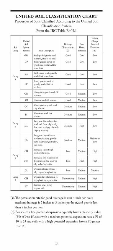
UnifiedSoilClassificationChart
Table2-1MinimumConcreteTemperatures
MaximumAnchorBoltSpacingforSupportedFoundationWall
AppendixTable1[Basedonthe2006IRCTableR404.1.1(1)PlainMasonryFoundationWalls]
AppendixTable2[Basedonthe2006IRCTableR404.1.1(2)]8InchMasonryFoundationWallswithReinforcing[d>5inches(a)]
AppendixTable3[BasedonIRCTableR404.1.1(3)]10InchMasonryFoundationWallswithReinforcing[d>6.75inches(a)]
AppendixTable4[BasedonIRCTableR404.1.1(4)]12InchMasonryFoundationWallswithReinforcing[d>8.75inches(a)]
AppendixTable6[BasedonIRCTableR404.1.1(6)]8"CantileveredConcreteandMasonryFoundationWalls
AppendixTable7[BasedonIRCTableR404.1.1(7)]10"CantileveredConcreteandMasonryFoundationWalls
AppendixTable8[BasedonIRCTableR404.1.1(8)]12"CantileveredConcreteandMasonryFoundationWalls
Diagrams
MinnesotaFrostDepthMap
Diagram1-FoundationWall(uppersection)
Diagram2-FoundationWall(lowersection)
Diagram3-CantileverWallSection
Diagram4-TypicalProppedCantileveredWallSection
Mortar Cards
1)MortarCementandMasonryCement
2)PortlandCementandLime
A
B
UNIFIED SOIl ClaSSIFICaTION CHaRTPropertiesofSoilsClassifiedAccordingtotheUnifiedSoil
ClassificationSystemFromtheIRCTableR405.1
SoilGroup
UnifiedSoil
SystemSymbol SolidDescription
DrainageCharacteristics
(a)
FrostHeave
Potential
Volume Change Potential
Expansion(b)
Group1
GW
GP
Well-gradedgravels,sandmixtures,littleornofines.Poorly-gradedgravelsorgravelsandmixtures,littleor no fines.
Good
Good
Low
Low
Low
Low
SW Wellgradedsands,gravellysands, little or no fines. Good Low Low
SPPoorly-gradedsandsorgravelly sands, little or no fines.
Good Low Low
GM Siltygravels,gravel-sand-siltmixtures. Good Medium Low
SM Siltyandsand-siltmixture. Good Medium Low
Group2
GC Clayeygravels,gravel-sand-claymixture. Medium Medium Low
SC Claysands,sand-claymixture. Medium Medium Low
ML
Inorganicsiltsandveryfinesand,rockflour,siltyorclayfine sands or clayey silts with slightly plasticity.
Medium High Low
CL
Inorganicclaysoflowtomedium plasticity, gravelly clays, sandy clays, silty clays, lean clays.
Medium Medium MediumtoLow
Group3
CH Inorganicclaysofhighplasticity, fat clays. Poor Medium High
MHInorganicsilts,micaceousordiatomaceous fine sandy or silty soils, classic silts.
Poor High High
Group4
OL Organicsiltsandorganicsilty clays of low plasticity. Poor Medium Medium
OH Organicclaysofmediumtohigh plasticity, organic silts. Unsatisfactory Medium High
PT Peatandotherhighlyorganic soils. Unsatisfactory Medium High
(a).Thepercolationrateforgooddrainageisover4inchperhour,mediumdrainageis2inchesto3inchesperhour,andpoorislessthan2inchesperhour.
(b).Soilswithalowpotentialexpansiontypicallyhaveaplasticityindex(PI)of0to15,soilswithamediumpotentialexpansionhaveaPIof10to35andsoilswithahighpotentialexpansionhaveaPIgreaterthan20.
C
D
E
F
Portland Cement and LimeProportion Specifications
Type
Type IPortlandM
S
N
Lime
Type IPortland
Lime
Type IPortland
Lime
* Approximate
Note: 1 1⁄2 5 Gallon Buckets = 1 Cubic Foot of Sand
1⁄4
1⁄2
Cementitious(bags)
Sand-damp and loose Water*
(5 gallon buckets)
5 1/2
6 3/4
9
1
1 1/4
1 1/2
Mortar Cement and Masonry CementProportion Specifications
Type
Type MMortar/MasonryM
S
N
Type SMortar/Masonry
Type NMortar/Masonry
* Approximate
Note: 1 1⁄2 5 Gallon Buckets = 1 Cubic Foot of Sand
Cementitious(bags)
Sand-damp and loose Water*
(5 gallon buckets)
4 1/2
4 1/23/4
4 1/2
1
1
G
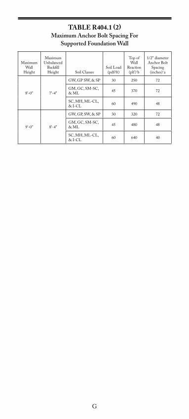
TaBlE R404.1 (2)Maximum Anchor Bolt Spacing For
Supported Foundation Wall
MaximumWall
Height
MaximumUnbalanced
BackfillHeight SoilClasses
SoilLoad(pdf/ft)
TopofWall
Reaction(plf )ˆb
1/2"diameterAnchorBolt
Spacing(inches)ˆa
8'-0" 7'-4"
GW,GPSW,&SP 30 250 72
GM,GC,SM-SC,&ML 45 370 72
SC,MH,ML-CL,&I-CL 60 490 48
9'-0" 8'-4"
GW,GP,SW,&SP 30 320 72
GM,GC,SM-SC,&ML 45 480 48
SC,MH,ML-CL,&I-CL 60 640 40
H
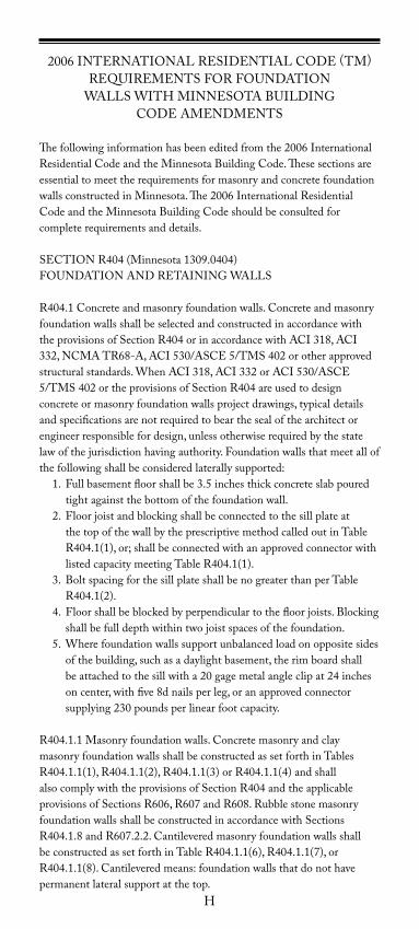
2006INTERNATIONALRESIDENTIALCODE(TM)REQUIREMENTSFORFOUNDATION
WALLSWITHMINNESOTABUILDING CODEAMENDMENTS
Thefollowinginformationhasbeeneditedfromthe2006InternationalResidentialCodeandtheMinnesotaBuildingCode.ThesesectionsareessentialtomeettherequirementsformasonryandconcretefoundationwallsconstructedinMinnesota.The2006InternationalResidentialCodeandtheMinnesotaBuildingCodeshouldbeconsultedforcompleterequirementsanddetails.
SECTIONR404(Minnesota1309.0404)FOUNDATIONANDRETAININGWALLS
R404.1Concreteandmasonryfoundationwalls.Concreteandmasonryfoundation walls shall be selected and constructed in accordance with theprovisionsofSectionR404orinaccordancewithACI318,ACI332,NCMATR68-A,ACI530/ASCE5/TMS402orotherapprovedstructuralstandards.WhenACI318,ACI332orACI530/ASCE5/TMS402ortheprovisionsofSectionR404areusedtodesignconcrete or masonry foundation walls project drawings, typical details andspecificationsarenotrequiredtobearthesealofthearchitectorengineerresponsiblefordesign,unlessotherwiserequiredbythestatelawofthejurisdictionhavingauthority.Foundationwallsthatmeetallofthefollowingshallbeconsideredlaterallysupported: 1. Fullbasementfloorshallbe3.5inchesthickconcreteslabpoured
tight against the bottom of the foundation wall. 2. Floorjoistandblockingshallbeconnectedtothesillplateat
thetopofthewallbytheprescriptivemethodcalledoutinTableR404.1(1),or;shallbeconnectedwithanapprovedconnectorwithlistedcapacitymeetingTableR404.1(1).
3. BoltspacingforthesillplateshallbenogreaterthanperTableR404.1(2).
4. Floorshallbeblockedbyperpendiculartothefloorjoists.Blockingshall be full depth within two joist spaces of the foundation.
5. Wherefoundationwallssupportunbalancedloadonoppositesidesof the building, such as a daylight basement, the rim board shall beattachedtothesillwitha20gagemetalangleclipat24inchesoncenter,withfive8dnailsperleg,oranapprovedconnectorsupplying230poundsperlinearfootcapacity.
R404.1.1Masonryfoundationwalls.ConcretemasonryandclaymasonryfoundationwallsshallbeconstructedassetforthinTablesR404.1.1(1),R404.1.1(2),R404.1.1(3)orR404.1.1(4)andshallalsocomplywiththeprovisionsofSectionR404andtheapplicableprovisionsofSectionsR606,R607andR608.RubblestonemasonryfoundationwallsshallbeconstructedinaccordancewithSectionsR404.1.8andR607.2.2.CantileveredmasonryfoundationwallsshallbeconstructedassetforthinTableR404.1.1(6),R404.1.1(7),orR404.1.1(8).Cantileveredmeans:foundationwallsthatdonothavepermanent lateral support at the top.
I
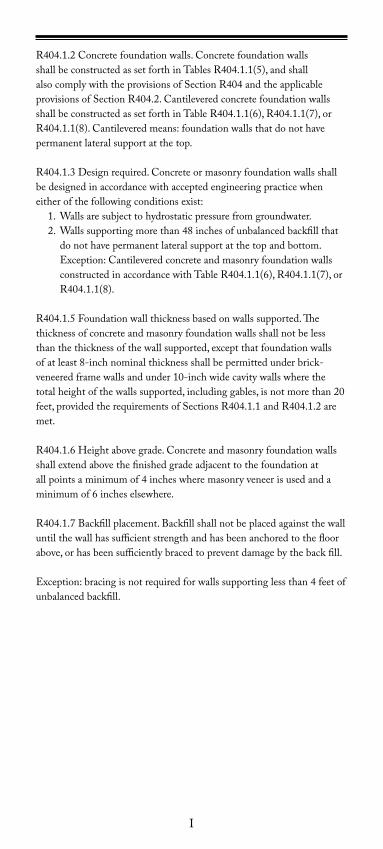
R404.1.2Concretefoundationwalls.ConcretefoundationwallsshallbeconstructedassetforthinTablesR404.1.1(5),andshallalsocomplywiththeprovisionsofSectionR404andtheapplicableprovisionsofSectionR404.2.CantileveredconcretefoundationwallsshallbeconstructedassetforthinTableR404.1.1(6),R404.1.1(7),orR404.1.1(8).Cantileveredmeans:foundationwallsthatdonothavepermanent lateral support at the top.
R404.1.3Designrequired.Concreteormasonryfoundationwallsshallbe designed in accordance with accepted engineering practice when eitherofthefollowingconditionsexist: 1. Wallsaresubjecttohydrostaticpressurefromgroundwater. 2. Wallssupportingmorethan48inchesofunbalancedbackfillthat
do not have permanent lateral support at the top and bottom. Exception:CantileveredconcreteandmasonryfoundationwallsconstructedinaccordancewithTableR404.1.1(6),R404.1.1(7),orR404.1.1(8).
R404.1.5Foundationwallthicknessbasedonwallssupported.Thethicknessofconcreteandmasonryfoundationwallsshallnotbelessthanthethicknessofthewallsupported,exceptthatfoundationwallsofatleast8-inchnominalthicknessshallbepermittedunderbrick-veneeredframewallsandunder10-inchwidecavitywallswherethetotalheightofthewallssupported,includinggables,isnotmorethan20feet,providedtherequirementsofSectionsR404.1.1andR404.1.2aremet.
R404.1.6Heightabovegrade.Concreteandmasonryfoundationwallsshallextendabovethefinishedgradeadjacenttothefoundationatallpointsaminimumof4incheswheremasonryveneerisusedandaminimumof6incheselsewhere.
R404.1.7Backfillplacement.Backfillshallnotbeplacedagainstthewalluntilthewallhassufficientstrengthandhasbeenanchoredtothefloorabove,orhasbeensufficientlybracedtopreventdamagebythebackfill.
Exception:bracingisnotrequiredforwallssupportinglessthan4feetofunbalancedbackfill.
J
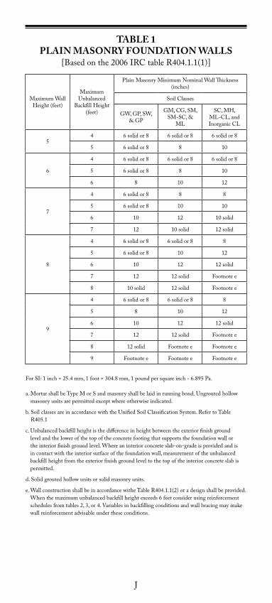
TaBlE 1PlaIN MaSONRy FOUNDaTION WallS
[Basedonthe2006IRCtableR404.1.1(1)]
MaximumWallHeight(feet)
MaximumUnbalanced
BackfillHeight(feet)
PlainMasonryMinimumNominalWallThickness(inches)
SoilClasses
GW,GP,SW,&GP
GM,CG,SM,SM-SC,&
ML
SC,MH,ML-CL,andInorganicCL
54 6solidor8 6solidor8 6solidor8
5 6solidor8 8 10
6
4 6solidor8 6solidor8 6solidor8
5 6solidor8 8 10
6 8 10 12
7
4 6solidor8 8 8
5 6solidor8 10 10
6 10 12 10solid
7 12 10solid 12solid
8
4 6solidor8 6solidor8 8
5 6solidor8 10 12
6 10 12 12solid
7 12 12solid Footnotee
8 10solid 12solid Footnotee
9
4 6solidor8 6solidor8 8
5 8 10 12
6 10 12 12solid
7 12 12solid Footnotee
8 12solid Footnotee Footnotee
9 Footnotee Footnotee Footnotee
ForSI:1inch=25.4mm,1foot=304.8mm,1poundpersquareinch-6.895Pa.
a.MortarshallbeTypeMorSandmasonryshallbelaidinrunningbond.Ungroutedhollowmasonryunitsarepermittedexceptwhereotherwiseindicated.
b.SoilclassesareinaccordancewiththeUnifiedSoilClassificationSystem.RefertoTableR405.1
c.Unbalancedbackfillheightisthedifferenceinheightbetweentheexteriorfinishgroundlevel and the lower of the top of the concrete footing that supports the foundation wall or theinteriorfinishgroundlevel.Whereaninteriorconcreteslab-on-gradeisprovidedandisin contact with the interior surface of the foundation wall, measurement of the unbalanced backfillheightfromtheexteriorfinishgroundleveltothetopoftheinteriorconcreteslabispermitted.
d.Solidgroutedhollowunitsorsolidmasonryunits.
e.WallconstructionshallbeinaccordancewitheTableR404.1.1(2)oradesignshallbeprovided.Whenthemaximumunbalancedbackfillheightexceeds6feetconsiderusingreinforcementschedulesfromtables2,3,or4.Variablesinbackfillingconditionsandwallbracingmaymakewall reinforcement advisable under these conditions.
K
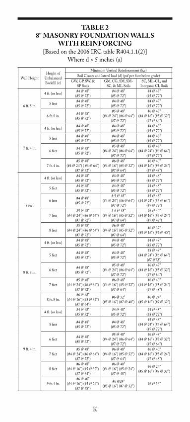
TaBlE 28" MaSONRy FOUNDaTION WallS
WITH REINFORCING[Basedonthe2006IRCtableR404.1.1(2)]
Whered>5inches(a)
WallHeightHeightof
UnbalancedBackfill(e)
MinimumVerticalReinforcement(b,c)SoilClassesandlateralload(d)(psfperfootbelowgrade)
GW,GP,SW,&SPSoils
GM,CG,SM,SM-SC,&MLSoils
SC,ML-CL,and InorganicCLSoils
6ft.8in.
4ft.(orless) #4@48"(#5@72")
#4@48"(#5@72")
#4@48"(#5@72")
5feet #4@48"(#5@72")
#4@48"(#5@72")
#4@48"(#5@72")
6ft.8in. #4@48"(#5@72")
#5@48"(#4@24")(#6@64")
(#7@72")
#6@48"(#4@16")(#5@32")
(#7@64")
7ft.4in.
4ft.(orless) #4@48"(#5@72")
#4@48"(#5@72")
#4@48"(#5@72")
5feet #4@48"(#5@72")
#4@48"(#5@72")
#4@48"(#5@72")
6feet #4@48"(#5@72")
#5@48"(#4@24")(#6@64")
(#7@72")
#5@48"(#4@24")(#6@64")
(#7@72")
7ft.4in.#5@48"
(#4@24")(#6@64")(#7@72")
#6@48"(#4@16")(#5@32")
(#7@64")
#6@40"(#4@16")(#5@24")
(#7@48")
8feet
4ft.(orless) #4@48"(#5@72")
#4@48"(#5@72")
#4@48"(#5@72")
5feet #4@48"(#5@72")
#4@48"(#5@72")
#4@48"(#5@72")
6feet #4@48"(#5@72")
#5@48"(#4@24")(#6@64")
(#7@72")
#5@48"(#4@24")(#6@64")
(#7@72")
7feet#5@48"
(#4@24")(#6@64")(#7@72")
#6@48"(#4@16")(#5@32")
(#7@64")
#6@40"(#4@16")(#5@24")
(#7@48")
8feet#5@48"
(#4@24")(#6@64")(#7@72")
#6@48"(#4@16")(#5@32")
(#7@64")
#6@32"(#5@16")(#7@40")
8ft.8in.
4ft.(orless) #4@48"(#5@72")
#4@48"(#5@72")
#4@48"(#5@72")
5feet #4@48"(#5@72")
#4@48"(#5@72")
#5@48"(#4@24")(#6@64")
(#7@72")
6feet #4@48"(#5@72")
#5@48"(#4@24")(#6@64")
(#7@72")
#6@48"(#4@16")(#5@32")
(#7@64")
7feet#5@48"
(#4@24")(#6@64")(#7@72")
#6@48"(#4@16")(#5@32")
(#7@64")
#6@40"(#4@16")(#5@24")
(#7@48")
8ft.8in.#6@48"
(#4@16")(#5@32")(#7@64")
#6@32"(#5@16")(#7@40")
#6@24"(#5@16")(#7@32")
9ft.4in.
4ft.(orless) #4@48"(#5@72")
#4@48"(#5@72")
#4@48"(#5@72")
5feet #4@48"(#5@72")
#4@48"(#5@72")
#5@48"(#4@24")(#6@64")
(#7@72")
6feet #4@48"(#5@72")
#5@48"(#4@24")(#6@64")
(#7@72")
#6@48"(#4@16")(#5@32")
(#7@64")
7feet#5@48"
(#4@24")(#6@64")(#7@72")
#6@48"(#4@16")(#5@32")
(#7@64")
#6@40"(#4@16")(#5@24")
(#7@48")
8feet#6@48"
(#4@16")(#5@32")(#7@64")
#6@40"(#4@16")(#5@24")
(#7@48")
#6@24"(#5@16")(#7@32")
9ft.4in.#6@40"
(#4@16")(#5@24")(#7@48")
#6@24"(#5@16")(#7@32") #6@16"
L
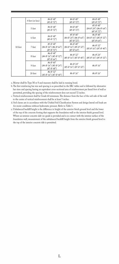
10feet
4feet(orless) #4@48"(#5@72")
#4@48"(#5@72")
#4@48"(#5@72")
5feet #4@48"(#5@72")
#4@48"(#5@72")
#5@48"(#4@24")(#6@64")
(#7@72")
6feet #4@48"(#5@72")
#5@48"(#4@24")(#6@64")
(#7@72")
#6@48"(#4@16")(#5@32")
(#7@64")
7feet#5@48"
(#4@24")(#6@64")(#7@72")
#6@48"(#4@16")(#5@32")
(#7@64")
#6@32"(#5@16")(#7@40")
8feet#6@48"
(#4@16")(#5@32")(#7@64")
#6@32"(#5@16")(#7@40")
#6@24"(#5@16")(#7@32")
9feet#6@40"
(#4@16")(#5@24")(#7@48")
#6@24"(#5@16")(#7@32") #6@16"
10feet #6@32"(#5@16")(#7@40") #6@16" #6@16"
a.MortarshallbeTypeMorSandmasonryshallbelaidinrunningbond.b.ThefirstreinforcingbarsizeandspacingisasprescribedintheIRCtablesandisfollowedbyalternative
barsizesandspacinghavinganequivalentcross-sectionalareaofreinforcementperlinealfootofwallaspermitted,providingthespacingofthereinforcementdoesnotexceed72inches.
c.VerticalreinforcementshallbeGrade60minimum.Thedistancefromthefaceofthesoilsideofthewalltothecenterofverticalreinforcementshallbeatleast5inches.
d.SoilclassesareinaccordancewiththeUnifiedSoilClassificationSystemanddesignlateralsoilloadsareformoistconditionswithouthydrostaticpressure.RefertoTable1.
e.Unbalancedbackfillheightisthedifferenceinheightoftheexteriorfinishgroundlevelandthelowerof the top of the concrete footing that supports the foundation wall or the interior finish ground level. Whereaninteriorconcreteslab-on-gradeisprovidedandisincontactwiththeinteriorsurfaceofthefoundationwall,measurementoftheunbalancedbackfillheightfromtheexteriorfinishgroundleveltothe top of the interior concrete slab is permitted.
M
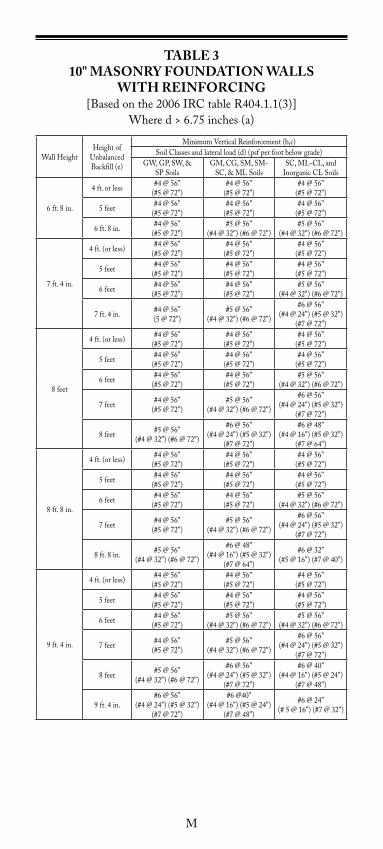
TaBlE 310" MaSONRy FOUNDaTION WallS
WITH REINFORCING[Basedonthe2006IRCtableR404.1.1(3)]
Whered>6.75inches(a)
WallHeightHeightof
UnbalancedBackfill(e)
MinimumVerticalReinforcement(b,c)SoilClassesandlateralload(d)(psfperfootbelowgrade)
GW,GP,SW,&SPSoils
GM,CG,SM,SM-SC,&MLSoils
SC,ML-CL,and InorganicCLSoils
6ft.8in.
4ft.orless #4@56"(#5@72")
#4@56"(#5@72")
#4@56"(#5@72")
5feet #4@56"(#5@72")
#4@56"(#5@72")
#4@56"(#5@72")
6ft.8in. #4@56"(#5@72")
#5@56"(#4@32")(#6@72")
#5@56"(#4@32")(#6@72")
7ft.4in.
4ft.(orless) #4@56"(#5@72")
#4@56"(#5@72")
#4@56"(#5@72")
5feet #4@56"(#5@72")
#4@56"(#5@72")
#4@56"(#5@72")
6feet #4@56"(#5@72")
#4@56"(#5@72")
#5@56"(#4@32")(#6@72")
7ft.4in. #4@56"(5@72")
#5@56"(#4@32")(#6@72")
#6@56"(#4@24")(#5@32")
(#7@72")
8feet
4ft.(orless) #4@56"(#5@72")
#4@56"(#5@72")
#4@56"(#5@72")
5feet #4@56"(#5@72")
#4@56"(#5@72")
#4@56"(#5@72")
6feet #4@56"(#5@72")
#4@56"(#5@72")
#5@56"(#4@32")(#6@72")
7feet #4@56"(#5@72")
#5@56"(#4@32")(#6@72")
#6@56"(#4@24")(#5@32")
(#7@72")
8feet #5@56"(#4@32")(#6@72")
#6@56"(#4@24")(#5@32")
(#7@72")
#6@48"(#4@16")(#5@32")
(#7@64")
8ft.8in.
4ft.(orless) #4@56"(#5@72")
#4@56"(#5@72")
#4@56"(#5@72")
5feet #4@56"(#5@72")
#4@56"(#5@72")
#4@56"(#5@72")
6feet #4@56"(#5@72")
#4@56"(#5@72")
#5@56"(#4@32")(#6@72")
7feet #4@56"(#5@72")
#5@56"(#4@32")(#6@72")
#6@56"(#4@24")(#5@32")
(#7@72")
8ft.8in. #5@56"(#4@32")(#6@72")
#6@48"(#4@16")(#5@32")
(#7@64")
#6@32"(#5@16")(#7@40")
9ft.4in.
4ft.(orless) #4@56"(#5@72")
#4@56"(#5@72")
#4@56"(#5@72")
5feet #4@56"(#5@72")
#4@56"(#5@72")
#4@56"(#5@72")
6feet #4@56"(#5@72")
#5@56"(#4@32")(#6@72")
#5@56"(#4@32")(#6@72")
7feet #4@56"(#5@72")
#5@56"(#4@32")(#6@72")
#6@56"(#4@24")(#5@32")
(#7@72")
8feet #5@56"(#4@32")(#6@72")
#6@56"(#4@24")(#5@32")
(#7@72")
#6@40"(#4@16")(#5@24")
(#7@48")
9ft.4in.#6@56"
(#4@24")(#5@32")(#7@72")
#6@40"(#4@16")(#5@24")
(#7@48")
#6@24"(#5@16")(#7@32")
N
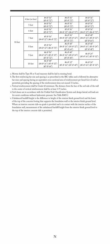
10feet
4feet(orless) #4@56"(#5@72")
#4@56"(#5@72")
#4@56"(#5@72")
5feet #4@56"(#5@72")
#4@56"(#5@72")
#4@56"(#5@72")
6feet #4@56"(#5@72")
#5@56"(#4@32")(#6@72")
#5@56"(#4@32")(#6@72")
7feet #5@56"(#4@32")(#6@72")
#6@56"(#4@24")(#5@32")
(#7@72")
#6@48"(#4@16")(#5@32")
(#7@64")
8feet #5@56"(#4@32")(#6@72")
#6@48"(#4@16")(#5@32")
(#7@64")
#6@40"(#4@16")(#5@24")
(#7@48")
9feet#6@56"
(#4@24")(#5@32")(#7@72")
#6@40"(#4@16")(#5@24")
(#7@48")
#6@24"(#5@16")(#7@32")
10feet#6@48"
(#4@16")(#5@32")(#7@64")
#6@32"(#5@16")(#7@40")
#6@24"(#5@16")(#7@32")
a.MortarshallbeTypeMorSandmasonryshallbelaidinrunningbond.b.ThefirstreinforcingbarsizeandspacingisasprescribedintheIRCtablesandisfollowedbyalternative
barsizesandspacinghavinganequivalentcross-sectionalareaofreinforcementperlinealfootofwallaspermitted,providingthespacingofthereinforcementdoesnotexceed72inches.
c.VerticalreinforcementshallbeGrade60minimum.Thedistancefromthefaceofthesoilsideofthewalltothecenterofverticalreinforcementshallbeatleast3.75inches.
d.SoilclassesareinaccordancewiththeUnifiedSoilClassificationSystemanddesignlateralsoilloadsareformoistconditionswithouthydrostaticpressure.SeeTableR405.1
e.Unbalancedbackfillheightisthedifferenceinheightoftheexteriorfinishgroundlevelandthelowerof the top of the concrete footing that supports the foundation wall or the interior finish ground level. Whereaninteriorconcreteslab-on-gradeisprovidedandisincontactwiththeinteriorsurfaceofthefoundationwall,measurementoftheunbalancedbackfillheightfromtheexteriorfinishgroundleveltothe top of the interior concrete slab is permitted.
O
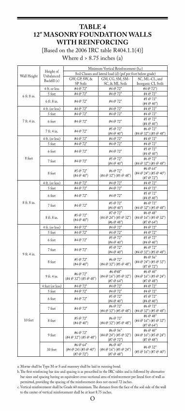
TaBlE 412" MaSONRy FOUNDaTION WallS
WITH REINFORCING[Basedonthe2006IRCtableR404.1.1(4)]
Whered>8.75inches(a)
WallHeightHeightof
UnbalancedBackfill(e)
MinimumVerticalReinforcement(b,c)SoilClassesandlateralload(d)(psfperfootbelowgrade)
GW,GP,SW,&SPSoils
GM,CG,SM,SM-SC,&MLSoils
SC,ML-CL,and InorganicCLSoils
6ft.8in.
4ft.orless #4@72" #4@72" #4@72")5feet #4@72" #4@72" #4@72"
6ft.8in. #4@72" #4@72" #5@72"(#4@40")
7ft.4in.
4ft.(orless) #4@72" #4@72" #4@72"5feet #4@72" #4@72" #4@72"
6feet #4@72" #4@72" #5@72"(#4@40")
7ft.4in. #4@72" #5@72"(#4@40")
#6@72"(#4@32")(#5@48")
8feet
4ft.(orless) #4@72" #4@72" #4@72"5feet #4@72" #4@72" #4@72"
6feet #4@72" #4@72" #5@72"(#4@40")
7feet #4@72" #5@72"(#4@40")
#6@72"(#4@32")(#5@48")
8feet #5@72"(#4@40")
#6@72"(#4@32")(#5@48")
#6@64"(#4@24")(#5@40")
(#7@72")
8ft.8in.
4ft.(orless) #4@72" #4@72" #4@72"5feet #4@72" #4@72" #4@72"
6feet #4@72" #4@72" #5@72"(#4@40")
7feet #4@72" #5@72"(#4@40")
#6@72"(#4@32")(#5@48")
8ft.8in. #5@72"(#4@40")
#7@72"(#4@24")(#5@32")
(#6@48")
#6@48"(#4@16")(#5@32")
(#7@64")
9ft.4in.
4ft.(orless) #4@72" #4@72" #4@72"5feet #4@72" #4@72" #4@72"
6feet #4@72" #5@72"(#4@40")
#5@72"(#4@40")
7feet #4@72" #5@72"(#4@40")
#6@72"(#4@32")(#5@48")
8feet #5@72"(#4@40")
#6@72"(#4@32")(#5@48")
#6@56"(#4@24")(#5@32")
(#7@72")
9ft.4in. #6@72"(#4@32")(#5@48")
#6@48"(#4@16")(#5@32")
(#7@64")
#6@40"(#4@16")(#5@24")
(#7@48")
10feet
4feet(orless) #4@72" #4@72" #4@72"5feet #4@72" #4@72" #4@72"
6feet #4@72" #5@72"(#4@40")
#5@72"(#4@40")
7feet #4@72" #6@72"(#4@32")(#5@48")
#6@72"(#4@32")(#5@48")
8feet #5@72"(#4@40")
#6@72"(#4@32")(#5@48")
#6@48"(#4@16")(#5@32")
(#7@64")
9feet #6@72"(#4@32")(#5@48")
#6@56"(#4@24")(#5@32")
(#7@72")
#6@40"(#4@16")(#5@24")
(#7@48")
10feet#6@64"
(#4@24)(#5@40")(#7@72")
#6@40"(#4@16")(#5@24")
(#7@48")
#6@32"(#5@16")(#7@40")
a.MortarshallbeTypeMorSandmasonryshallbelaidinrunningbond.b.ThefirstreinforcingbarsizeandspacingisasprescribedintheIRCtablesandisfollowedbyalternative
barsizesandspacinghavinganequivalentcross-sectionalareaofreinforcementperlinealfootofwallaspermitted,providingthespacingofthereinforcementdoesnotexceed72inches.
c.VerticalreinforcementshallbeGrade60minimum.Thedistancefromthefaceofthesoilsideofthewalltothecenterofverticalreinforcementshallbeatleast8.75inches.
P
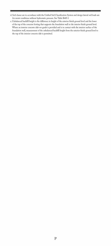
d.SoilclassesareinaccordancewiththeUnifiedSoilClassificationSystemanddesignlateralsoilloadsareformoistconditionswithouthydrostaticpressure.SeeTableR405.1
e.Unbalancedbackfillheightisthedifferenceinheightoftheexteriorfinishgroundlevelandthelowerof the top of the concrete footing that supports the foundation wall or the interior finish ground level. Whereaninteriorconcreteslab-on-gradeisprovidedandisincontactwiththeinteriorsurfaceofthefoundationwall,measurementoftheunbalancedbackfillheightfromtheexteriorfinishgroundleveltothe top of the interior concrete slab is permitted.
Q
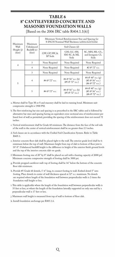
TaBlE 68" CaNTIlEvERED CONCRETE aND
MaSONRy FOUNDaTION WallS[Basedonthe2006IRCtableR404.1.1(6)]
MaximumWall
Height(j)(feet)
MaximumUnbalancedBackfill(e)
(feet)
MinimumVerticalReinforcementSizeandSpacingfor 8-INCHNominalWallThickness(a)(b)(c)(e)(f )(i)(k)
SoilClasses(d)
GW,GP,SW,&SPSoils
GM,GC,SM,SM-SC,&ML
Soils
SC,MH,ML-CL,andInorganicCL
Soils
43 NoneRequired NoneRequired NoneRequired
4 NoneRequired NoneRequired #2@72"o.c.
5
3 NoneRequired NoneRequired NoneRequired
4 #4@72"o.c. #4@56"o.c.(h)(#5@72"o.c.)
#4@40"o.c.(g)(#5@56"o.c.) (#6@72"o.c.)
5 #4@72"o.c. #4@56"o.c.(h)(#5@72"o.c.)
#4@40"o.c.(g)(#5@56"o.c.) (#6@72"o.c.)
a.MortarshallbeTypeMorSandmasonryshallbelaidinrunningbond.Minimumunitcompressivestrengthis1900PSI.
b.ThefirstreinforcingbarsizeandspacingisasprescribedintheIRCtablesandisfollowedbyalternativebarsizesandspacinghavinganequivalentcross-sectionalareaofreinforcementperlinealfootofwallaspermitted,providingthespacingofthereinforcementdoesnotexceed72inches.
c.VerticalreinforcementshallbeGrade60minimum.Thedistancefromthefaceofthesoilsideofthewalltothecenterofverticalreinforcementshallbenogreaterthan2.5inches.
d.SoilclassesareinaccordancewiththeUnifiedSoilClassificationSystem.RefertoTableR405.1.
e.Interiorconcretefloorslabshallbeplacedtighttothewall.Theexteriorgradelevelshallbe6:minimumbelowthetopofwall.Maximumheightfromtopofslabtobottomoffloorjoistis10'-0".Unbalancedbackfillheightisthedifferenceinheightoftheexteriorfinishgroundlevelsandthetopoftheinteriorconcreteslab-on-grade.
f.Minimumfootingsizeof20"by8"shallbeplacedonsoilwithabearingcapacityof2000psf.Minimumconcretecompressivestrengthoffootingshallbe3000psi.
g.Provideproppedcantileverwall:topoffootingshallbe16"belowthebottomoftheconcretefloorslabminimum.
h.Provide#5Grade60dowels,1'-6"long,toconnectfootingtowall.Embeddowel5"intofooting.Placedowelsincenterofwallthicknessspacedat32"o.c.maximum.Nodowelsarerequiredwherelengthofthefoundationwallbetweenperpendicularwallsis2timesthefoundation wall height or less.
i. This table is applicable where the length of the foundation wall between perpendicular walls is 35feetorless,orwherethelengthofthefoundationlaterallysupportedononlyoneendbyaperpendicularwallis17feetorless.
j.Maximumwallheightismeasuredfromtopofwalltobottomoffloorslab.
k.InstallfoundationanchorageperR403.1.6.
R
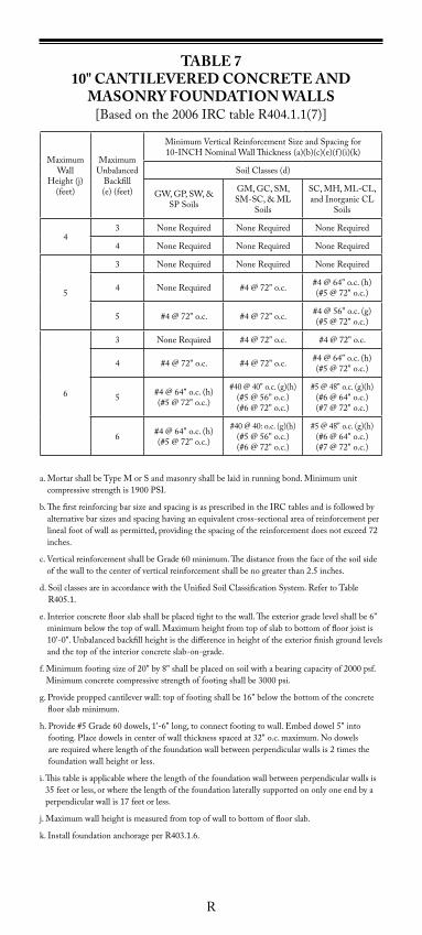
TaBlE 710" CaNTIlEvERED CONCRETE aND
MaSONRy FOUNDaTION WallS[Basedonthe2006IRCtableR404.1.1(7)]
MaximumWall
Height(j)(feet)
MaximumUnbalanced
Backfill (e)(feet)
MinimumVerticalReinforcementSizeandSpacingfor 10-INCHNominalWallThickness(a)(b)(c)(e)(f )(i)(k)
SoilClasses(d)
GW,GP,SW,&SPSoils
GM,GC,SM,SM-SC,&ML
Soils
SC,MH,ML-CL,andInorganicCL
Soils
43 NoneRequired NoneRequired NoneRequired
4 NoneRequired NoneRequired NoneRequired
5
3 NoneRequired NoneRequired NoneRequired
4 NoneRequired #4@72"o.c. #4@64"o.c.(h)(#5@72"o.c.)
5 #4@72"o.c. #4@72"o.c. #4@56"o.c.(g)(#5@72"o.c.)
6
3 NoneRequired #4@72"o.c. #4@72"o.c.
4 #4@72"o.c. #4@72"o.c. #4@64"o.c.(h)(#5@72"o.c.)
5 #4@64"o.c.(h)(#5@72"o.c.)
#40@40"o.c.(g)(h)(#5@56"o.c.) (#6@72"o.c.)
#5@48"o.c.(g)(h)(#6@64"o.c.) (#7@72"o.c.)
6 #4@64"o.c.(h)(#5@72"o.c.)
#40@40:o.c.(g)(h)(#5@56"o.c.) (#6@72"o.c.)
#5@48"o.c.(g)(h)(#6@64"o.c.) (#7@72"o.c.)
a.MortarshallbeTypeMorSandmasonryshallbelaidinrunningbond.Minimumunitcompressivestrengthis1900PSI.
b.ThefirstreinforcingbarsizeandspacingisasprescribedintheIRCtablesandisfollowedbyalternativebarsizesandspacinghavinganequivalentcross-sectionalareaofreinforcementperlinealfootofwallaspermitted,providingthespacingofthereinforcementdoesnotexceed72inches.
c.VerticalreinforcementshallbeGrade60minimum.Thedistancefromthefaceofthesoilsideofthewalltothecenterofverticalreinforcementshallbenogreaterthan2.5inches.
d.SoilclassesareinaccordancewiththeUnifiedSoilClassificationSystem.RefertoTableR405.1.
e.Interiorconcretefloorslabshallbeplacedtighttothewall.Theexteriorgradelevelshallbe6"minimumbelowthetopofwall.Maximumheightfromtopofslabtobottomoffloorjoistis10'-0".Unbalancedbackfillheightisthedifferenceinheightoftheexteriorfinishgroundlevelsandthetopoftheinteriorconcreteslab-on-grade.
f.Minimumfootingsizeof20"by8"shallbeplacedonsoilwithabearingcapacityof2000psf.Minimumconcretecompressivestrengthoffootingshallbe3000psi.
g.Provideproppedcantileverwall:topoffootingshallbe16"belowthebottomoftheconcretefloorslabminimum.
h.Provide#5Grade60dowels,1'-6"long,toconnectfootingtowall.Embeddowel5"intofooting.Placedowelsincenterofwallthicknessspacedat32"o.c.maximum.Nodowelsarerequiredwherelengthofthefoundationwallbetweenperpendicularwallsis2timesthefoundation wall height or less.
i. This table is applicable where the length of the foundation wall between perpendicular walls is 35feetorless,orwherethelengthofthefoundationlaterallysupportedononlyoneendbyaperpendicularwallis17feetorless.
j.Maximumwallheightismeasuredfromtopofwalltobottomoffloorslab.
k.InstallfoundationanchorageperR403.1.6.
S
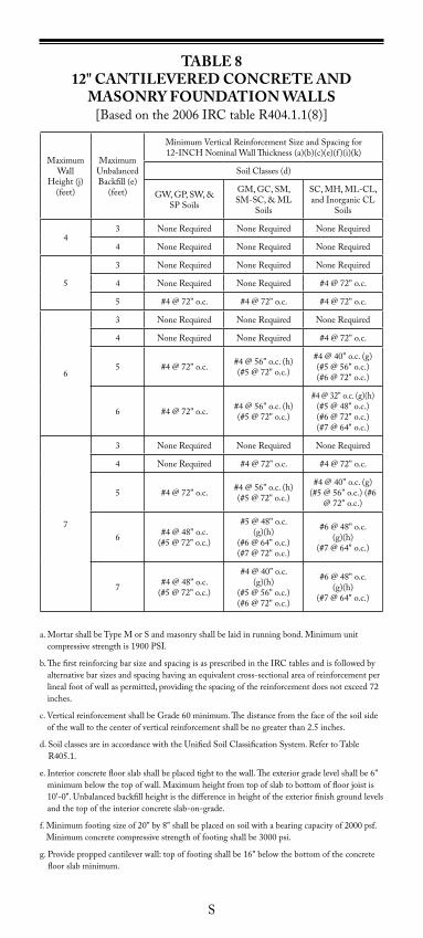
TaBlE 812" CaNTIlEvERED CONCRETE aND
MaSONRy FOUNDaTION WallS[Basedonthe2006IRCtableR404.1.1(8)]
MaximumWall
Height(j)(feet)
MaximumUnbalancedBackfill(e)
(feet)
MinimumVerticalReinforcementSizeandSpacingfor 12-INCHNominalWallThickness(a)(b)(c)(e)(f )(i)(k)
SoilClasses(d)
GW,GP,SW,&SPSoils
GM,GC,SM,SM-SC,&ML
Soils
SC,MH,ML-CL,andInorganicCL
Soils
43 NoneRequired NoneRequired NoneRequired
4 NoneRequired NoneRequired NoneRequired
5
3 NoneRequired NoneRequired NoneRequired
4 NoneRequired NoneRequired #4@72"o.c.
5 #4@72"o.c. #4@72"o.c. #4@72"o.c.
6
3 NoneRequired NoneRequired NoneRequired
4 NoneRequired NoneRequired #4@72"o.c.
5 #4@72"o.c. #4@56"o.c.(h)(#5@72"o.c.)
#4@40"o.c.(g)(#5@56"o.c.) (#6@72"o.c.)
6 #4@72"o.c. #4@56"o.c.(h)(#5@72"o.c.)
#4@32"o.c.(g)(h)(#5@48"o.c.) (#6@72"o.c.)(#7@64"o.c.)
7
3 NoneRequired NoneRequired NoneRequired
4 NoneRequired #4@72"o.c. #4@72"o.c.
5 #4@72"o.c. #4@56"o.c.(h)(#5@72"o.c.)
#4@40"o.c.(g)(#5@56"o.c.)(#6
@72"o.c.)
6 #4@48"o.c.(#5@72"o.c.)
#5@48"o.c.(g)(h)
(#6@64"o.c.) (#7@72"o.c.)
#6@48"o.c.(g)(h)
(#7@64"o.c.)
7 #4@48"o.c.(#5@72"o.c.)
#4@40"o.c.(g)(h)
(#5@56"o.c.) (#6@72"o.c.)
#6@48"o.c.(g)(h)
(#7@64"o.c.)
a.MortarshallbeTypeMorSandmasonryshallbelaidinrunningbond.Minimumunitcompressivestrengthis1900PSI.
b.ThefirstreinforcingbarsizeandspacingisasprescribedintheIRCtablesandisfollowedbyalternativebarsizesandspacinghavinganequivalentcross-sectionalareaofreinforcementperlinealfootofwallaspermitted,providingthespacingofthereinforcementdoesnotexceed72inches.
c.VerticalreinforcementshallbeGrade60minimum.Thedistancefromthefaceofthesoilsideofthewalltothecenterofverticalreinforcementshallbenogreaterthan2.5inches.
d.SoilclassesareinaccordancewiththeUnifiedSoilClassificationSystem.RefertoTableR405.1.
e.Interiorconcretefloorslabshallbeplacedtighttothewall.Theexteriorgradelevelshallbe6"minimumbelowthetopofwall.Maximumheightfromtopofslabtobottomoffloorjoistis10'-0".Unbalancedbackfillheightisthedifferenceinheightoftheexteriorfinishgroundlevelsandthetopoftheinteriorconcreteslab-on-grade.
f.Minimumfootingsizeof20"by8"shallbeplacedonsoilwithabearingcapacityof2000psf.Minimumconcretecompressivestrengthoffootingshallbe3000psi.
g.Provideproppedcantileverwall:topoffootingshallbe16"belowthebottomoftheconcretefloorslabminimum.
T
h.Provide#5Grade60dowels,1'-6"long,toconnectfootingtowall.Embeddowel5"intofooting.Placedowelsincenterofwallthicknessspacedat32"o.c.maximum.Nodowelsarerequiredwherelengthofthefoundationwallbetweenperpendicularwallsis2timesthefoundation wall height or less.
i. This table is applicable where the length of the foundation wall between perpendicular walls is 35feetorless,orwherethelengthofthefoundationlaterallysupportedononlyoneendbyaperpendicularwallis17feetorless.
j.Maximumwallheightismeasuredfromtopofwalltobottomoffloorslab.
k.InstallfoundationanchorageperR403.1.6.
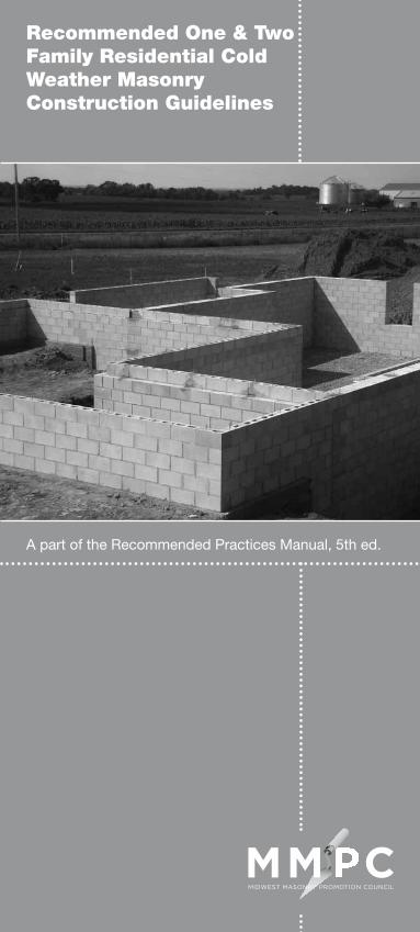
Recommended One & TwoFamily Residential ColdWeather MasonryConstruction Guidelines
A part of the Recommended Practices Manual, 5th ed.

NOTES
2.1
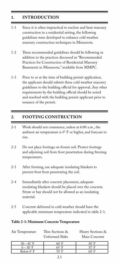
1. INTRODUCTION
1-1 Sinceitisoftenimpracticaltoencloseandheatmasonryconstruction in a residential setting, the following guidelines were developed to enhance cold weather masonryconstructiontechniquesinMinnesota.
1-2 These recommended guidelines should be following in additiontothepracticesdiscussedin“RecommendedPracticesforConstructionofResidentialMasonryBasementsinMinnesota,”availablefromMMPC.
1-3 Priortooratthetimeofbuildingpermitapplication,the applicant should submit these cold weather masonry guidelinestothebuildingofficialforapproval.Anyotherrequirementsbythebuildingofficialshouldbenotedand resolved with the building permit applicant prior to issuance of the permit.
2. FOOTING CONSTRUCTION
2-1 Workshouldnotcommence,unlessat6:00a.m.,theambientairtemperatureis0°Forhigher,andforecasttorise.
2-2 Donotplacefootingsonfrozensoil.Protectfootingsandadjoiningsoilfromfrostpenetrationduringfreezingtemperatures.
2-3 Afterforming,useadequateinsulatingblanketstoprevent frost from penetrating the soil.
2-4 Immediatelyafterconcreteplacement,adequateinsulatingblanketsshouldbeplacedovertheconcrete.Straworhayshouldnotbeallowedasaninsulatingmaterial.
2-5 Concrete delivered in cold weather should have the applicableminimumtemperatureindicatedintable2-1.
Table 2-1: Minimum Concrete Temperature
AirTemperature ThinSections& HeavySections& UnformedSlabs MassConcrete
30–45˚F 60˚F 50˚F0–30˚F 65˚F 55˚F
Below0˚F 70˚F 60˚F
2.2
Themaximumtemperatureofconcreteproducedwithheatedaggregates, heated water, or both, should at no time during its productionortransportationexceed90°F.Note: The temperature of the concrete produced during hot weather should be as low as practical.
3. MaSONRy MaTERIalS
3-1 Masonrymaterials(ConcreteBlock,BrickorStone)storedonthejobshouldbecoveredandkeptdry.
3-2 Allmasonrylaidshouldbefreefromiceandsnow.
3-3 Whenambienttemperaturesare25°Forlower,allwallsafterconstructionshouldbecoveredwithwind-resistantmaterial, on both sides, from the top of the wall down to the footings.
4. MORTaR aND GROUT
4-1 The following recommendations should be met for the following temperatures.
• Temperatures40°F-32°F ConstructionRequirements:Heatmaterialstoproducemortarorgroutbetween40°F-120°F (4°C-49°C).
• Temperatures32°Fandbelow ConstructionRequirements:Heatmaterialstoproducemortarorgroutbetween40°F-120°F (4°C-49°C).Maintainmortarorgroutabovefreezinguntilusedinmasonry.
4-2 AdditionalComments
a. Incoldweatherconditions,acceleratingtheinitialset time of mortar or grout materials may be desired.Useoneofthesemethods:
a.TypeIIImaybeusedinplaceofTypeIfor faster initial set time and faster initial strength gain.
b.Setacceleratedpre-blendedmortarmaybe used for faster initial set time and faster initial strength gain.
c.Aliquidsetacceleratormaybeaddedtomortar or grout for faster initial set time
2.3
and faster initial strength gain.
b.Mortarshouldbemixedinsmalleramountssoitcan be used before it cools.
c. Everyeffortshouldbemadetoproduceconsecutivebatches of mortar with consistent temperatures.
d.Coverwallswithwind-resistantmaterialstopreventrapid heat loss or water from entering masonry.
References:
1.“RecommendedOneandTwoFamilyColdWeatherMasonryConstructionGuidelines”,MinnesotaCodesandFireSafetyCouncil,1993.
Tables
Table2-1MinimumConcreteTemperatures
Diagrams
MinnesotaFrostDepthMap
Mortar Cards
1)MortarCementandMasonryCement
2)PortlandCementandLime

2.4
NOTES
2.5
RecommendedRadon Guidelines
A part of the Recommended Practices Manual, 5th ed.

NOTES
3.1
INTRODUCTION
AsofJune1,2009allnewhousesbuiltinMinnesotaarerequiredtoincludefeaturesdesignedtoresistorreducetheinfiltrationofradongas.Radon,anodorless,tastelessgasthatforms from the decay of naturally occurring uranium found in rockandsoilthroughoutMinnesota,isthesecondleadingcauseoflungcancerintheU.S. Thechangetothestatebuildingcoderequiresbuilderstoinstalla“passive”radonmitigationsystemthatdoesnotincludeapoweredexhaustfan.Thesesystemsreducesoilgasentrypointsand provide a route to vent the gases to the outdoors. Formoreinformationonthehealthrisksassociatedwithradon,visitwww.health.state.mn.us/radon.FormoreinformationonMinnesotabuildingcodesrelatedtoradon,contactDonSivigny,MNDepartmentofLabor&Industry,[email protected].
1322.2100 INCORPORaTION By REFERENCE
AppendixF,RadonControlMethods,ofthe2006editionoftheInternationalResidentialCode(AppendixF)aspromulgatedbytheInternationalCodeCouncil,Inc.(ICC),FallsChurch,VA22041,isincorporatedbyreferenceandmadepartoftheMinnesotaStateBuildingCodeexceptasqualifiedbytheapplicableprovisionsinchapter1300,andasamendedinparts1322.2101to1322.2103.AppendixFisnotsubjecttofrequentchangeandacopyofAppendixF,withamendmentsforusinMinnesota,isavailableintheofficeofthecommissioneroflaborandindustry.Portionsofparts1322.2101to1322.2103reproducetextandtablesfromAppendixF,whichiscopyrightedbytheICC.Allrightsreserved.
Statutory authority: MS s 326B.02; 326B.101; 326B.106; 326B.13
History: 33 SR 1480 Posted: June 17, 2009
3.2
1322.2101 SECTION aF101, SCOPE
Subpart1.General.AppendixF,SectionAF101,isamendedtoreadasfollows: Thepurposeofparts1322.2101to1322.2103istoestablishrequirementsforradon-resistantconstructioninnewresidentialconstructionbuilttotherequirementsofMinnesotaRules,chapter1305or1309.
Subp.2.Figure aF101.AppendixF,FigureAF101,isdeleted in its entirety.
Subp.3.Table aF101(1).AppendixF,TableAF101(1),is deleted in its entirety.
Statutory authority: MS s 326B.02; 326B.101; 326B.106; 326B.13
History: 33 SR 1480 Posted: June 17, 2009
3.3
1322.2102 SECTION aF102, DEFINITIONS
Subpart1.General. AppendixF,SectionAF102,isamendedtoreadasfollows: aF102.1 General. The definitions in this part apply to
MinnesotaRules,parts1322.2101 to 1322.2103.
SUB-SlaB DEPRESSURIZaTION SySTEM (Passive). Asystemdesignedtoachievelowersub-slabairpressurerelativeto indoor air pressure by use of a vent pipe routed through the conditionedspaceofabuildingandconnectingthesub-slabareawithoutdoorair,therebyrelyingontheconvectiveflowofairupward in the vent to draw air from beneath the slab.
SUB-SlaB DEPRESSURIZaTION SySTEM (active). Asystemdesignedtoachievelowersub-slabairpressurerelativetoindoorairpressurebyuseofafan-poweredventdrawingairfrom beneath the slab.
DRaIN TIlE lOOP.Acontinuouslengthofdraintileorperforatedpipeextendingaroundalloftheinternalperimeterofa basement or crawl space.
RaDON GaS.Anaturallyoccurring,chemicallyinert,radioactivegasthatisnotdetectablebyhumansenses.Asagas,itcanmovereadilythroughparticlesofsoilandrockandcanaccumulate under the slabs and foundations of homes where it caneasilyenterintothelivingspacethroughconstructioncracksand openings.
SOIl-GaS RETaRDER.Acontinuousmembraneof6-mil(0.15mm)polyethylene,3-mil(0.075mm)cross-laminatedpolyethylene,orotherequivalentmaterialusedtoretardtheflowof soil gases into a building.
SUB-MEMBRaNE DEPRESSURIZaTION SySTEM. Asystemdesignedtoachievelowersub-membraneairpressurerelative to crawl space air pressure by use of a vent drawing air frombeneaththesoil-gas-retardermembrane.
Subp.2.Figure aF102.
3.4
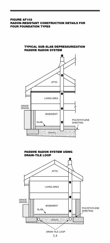
TYPICAL SUB-SLAB DEPRESSURIZATIONPASSIVE RADON SYSTEM
ATTIC
LIVING AREA
BASEMENT
SLABPOLYETHYLENESHEETING
GRAVEL
GRADEGRAVEL
PASSIVE RADON SYSTEM USINGDRAIN-TILE LOOP
FIGURE AF102RADON-RESISTANT CONSTRUCTION DETAILS FORFOUR FOUNDATION TYPES
ATTIC
LIVING AREA
BASEMENT
SLAB POLYETHYLENESHEETING
DRAIN TILE LOOP
GRADEGRAVEL
GRAVEL
3.5
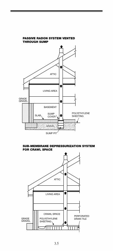
PASSIVE RADON SYSTEM VENTEDTHROUGH SUMP
SUB-MEMBRANE DEPRESSURIZATION SYSTEMFOR CRAWL SPACE
ATTIC
LIVING AREA
BASEMENT
SLABPOLYETHYLENESHEETING
GRAVEL
SUMP PIT
SUMPCOVER
GRADEGRAVEL
ATTIC
LIVING AREA
CRAWL SPACE
POLYETHYLENESHEETING
PERFORATEDDRAIN TILEGRADE
GRAVEL
3.6
1322.2103 SECTION aF103, REqUIREMENTS
AppendixF,SectionAF103,isamendedtoreadasfollows:
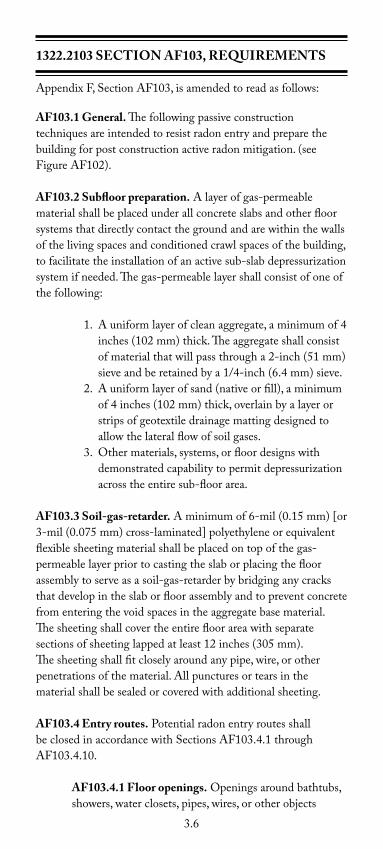
aF103.1 General. The following passive construction techniquesareintendedtoresistradonentryandpreparethebuildingforpostconstructionactiveradonmitigation.(seeFigureAF102).
aF103.2 Subfloor preparation.Alayerofgas-permeablematerialshallbeplacedunderallconcreteslabsandotherfloorsystems that directly contact the ground and are within the walls of the living spaces and conditioned crawl spaces of the building, tofacilitatetheinstallationofanactivesub-slabdepressurizationsystemifneeded.Thegas-permeablelayershallconsistofoneofthefollowing:
1.Auniformlayerofcleanaggregate,aminimumof4inches(102mm)thick.Theaggregateshallconsistofmaterialthatwillpassthrougha2-inch(51mm)sieveandberetainedbya1/4-inch(6.4mm)sieve.
2.Auniformlayerofsand(nativeorfill),aminimumof4inches(102mm)thick,overlainbyalayerorstripsofgeotextiledrainagemattingdesignedtoallowthelateralflowofsoilgases.
3.Othermaterials,systems,orfloordesignswithdemonstratedcapabilitytopermitdepressurizationacrosstheentiresub-floorarea.
aF103.3 Soil-gas-retarder.Aminimumof6-mil(0.15mm)[or3-mil(0.075mm)cross-laminated]polyethyleneorequivalentflexiblesheetingmaterialshallbeplacedontopofthegas-permeablelayerpriortocastingtheslaborplacingthefloorassemblytoserveasasoil-gas-retarderbybridginganycracksthatdevelopintheslaborfloorassemblyandtopreventconcretefrom entering the void spaces in the aggregate base material. Thesheetingshallcovertheentirefloorareawithseparatesectionsofsheetinglappedatleast12inches(305mm).The sheeting shall fit closely around any pipe, wire, or other penetrationsofthematerial.Allpuncturesortearsinthematerial shall be sealed or covered with additional sheeting.
aF103.4 Entry routes.PotentialradonentryroutesshallbeclosedinaccordancewithSectionsAF103.4.1throughAF103.4.10.
aF103.4.1 Floor openings.Openingsaroundbathtubs,showers, water closets, pipes, wires, or other objects

3.7
thatpenetrateconcreteslabsorotherfloorassembliesshallbefilledwithapolyurethanecaulkorequivalentsealant applied in accordance with the manufacturer’s recommendations.
aF103.4.2 Concrete joints.Allcontroljoints,isolationjoints, construction joints, and any other joints in concrete slabs or between slabs and foundation walls shallbesealedwithacaulkorsealant.Gapsand
joints shall be cleared of loose material and filled with polyurethanecaulkorotherelastomericsealantappliedin accordance with the manufacturer’s recommendations.
aF103.4.3 Condensate drains. Condensate drains shall
be trapped or routed through nonperforated pipe to daylight.
aF103.4.4 Sumps.Sumppitsopentosoilorservingastheterminationpointforsub-slaborinteriordraintileloopsshallbecoveredwithagasketedorotherwisesealedlid.Sumpsusedasthesuctionpointinasub-slabdepressurizationsystemshallhavealiddesignedtoaccommodatetheventpipe.Sumpsusedasafloordrainshallhavealidequippedwithatrappedinlet.
aF103.4.5 Foundation walls.Hollowblockmasonryfoundation walls shall be constructed with either a continuous course of solid masonry, one course of masonry grouted solid, or a solid concrete beam at or above finished ground surface to prevent passage of air fromtheinteriorofthewallintothelivingspace.Whereabrickveneerorothermasonryledgeisinstalled,thecourse immediately below that ledge shall be sealed. Joints,cracks,orotheropeningsaroundallpenetrationsofbothexteriorandinteriorsurfacesofmasonryblockorwood foundation walls below the ground surface shall
befilledwithpolyurethanecaulkorequivalentsealant.Penetrationsofconcretewallsshallbefilled.
aF103.4.6 Waterproofing/dampproofing.Theexteriorsurfacesofportionsofconcreteandmasonryblockwalls below the ground surface shall be dampproofed or waterproofedinaccordancewithSectionR406ofthiscode.
aF103.4.7 air-handling units.Air-handlingunitsincrawl spaces shall be sealed to prevent air from being drawn into the unit.
3.8
Exception:Unitswithgasketedseamsorunitsthatareotherwisesealedbythemanufacturertopreventleakage.
aF103.4.8 Ducts.Ductworkpassingthroughor beneath a slab shall be of seamless material unless the
air-handlingsystemisdesignedtomaintaincontinuouspositivepressurewithinsuchducting.Jointsinsuchductworkshallbesealedtopreventairleakage.
Ductworklocatedincrawlspacesshallhaveallseamsand joints sealed by closure systems in accordance with MinnesotaRules,chapter1346.
aF103.4.9 Unconditioned crawl space floors. Openingsaroundallpenetrationsthroughfloorsaboveunconditionedcrawlspacesshallbecaulkedorotherwisefilledtopreventairleakage.
aF103.4.10 Unconditioned crawl space access.Accessdoors and other openings or penetrations between basements and adjoining unconditioned crawl spaces shallbeclosed,gasketed,orotherwisefilledtopreventairleakage.
aF103.5 Passive sub-membrane depressurization system. Inbuildingswithcrawlspacefoundations,thefollowingcomponentsofapassivesub-membranedepressurizationsystemshall be installed during construction.
aF103.5.1 ventilation.Unconditionedcrawlspacesshallbeprovidedwithventstotheexteriorofthebuilding. The minimum net area of ventilation openings shallcomplywithSectionR408.1ofthiscode.
aF103.5.2 Soil-gas-retarder. The soil in crawl spaces shall be covered with a continuous layer of minimum
6-mil(0.14mm)polyethylenesoil-gas-retarder.Thegroundcovershallbelappedaminimumof12inches(305mm)atjointsandshallextendtoallfoundationwalls enclosing the crawl space area.
aF103.5.3 vent pipe. Aplumbingteeorotherapprovedconnectionshallbeinsertedhorizontallybeneaththesheetingwithone10-footsectionofaperforatedpipeconnectedtoeachsideofthe“T”fittingandthenconnectedtoa3-or4-inchdiameter(76mmor102mm)fittingwithaverticalventpipeinstalledthroughthe sheeting. The vent pipe shall be of solid piping
3.9
materialandshallbeextendedupthroughthebuildingfloors,terminatedatleast12inches(305mm)abovetheroofinalocationatleast10feet(3,048mm)away
from any window or other opening into the conditioned spacesofthebuildingthatislessthan2feet(610mm)
belowtheexhaustpoint,and10feet(3,048mm)fromany window or other opening in adjoining or adjacent buildings.
aF103.6 Passive sub-slab depressurization system. Inbuildingswithbasements,foundations,and/orconditionedcrawlspaces,orslab-on-gradebuildings,thefollowingcomponentsofapassivesub-slabdepressurizationsystemshallbe installed during construction. aF103.6.1 vent pipe.Aminimum3-inchdiameter(76
mm)ABS,PVC,orequivalentgastightpipeshallbeembeddedverticallyintothesub-slabaggregateorotherpermeablematerialbeforetheslabiscast.A“T”fittingwithone10-footsectionofaperforatedpipeconnectedtoeachsideofthe“T”fittingorequivalentmethodshallbe used to ensure that the pipe opening remains within thesub-slabpermeablematerial.Alternatively,the3-inch(76mm)pipeshallbeinserteddirectlyintoaninteriorperimeter drain tile loop or through a sealed sump cover wherethesumpisexposedtothesub-slabaggregateorconnected to it through a drainage system.
Thepipeshallbeextendedupthroughthebuildingfloors,terminateatleast12inches(305mm)abovethesurfaceoftheroofinalocationatleast10feet(3048mm)awayfromanywindoworotheropeningintotheconditionedspacesofthebuildingthatislessthan2feet(610mm)belowtheexhaustpoint,and10feet(3048mm)fromanywindoworotheropeninginadjoiningoradjacent buildings.
Exception:Ifanactivesub-slabdepressurizationsystemisinstalled, the vent pipe may be routed through unconditioned space within the building or garage, provided the vent pipe is in-sulatedtoaminimumofR-4.Radonventpipesshallterminateatleast12inchesabovetherooforshallbeconnectedtoasingleventthatterminatesatleast12inchesabovetheroof.Foractivesystems,asystemmonitoringdevicemustalsobeinstalled.Allotherrequirementsofthissectionapply.
aF103.6.2 Multiple vent pipes.Inbuildingswhereinteriorfootingsorotherbarriersseparatethesub-slab
3.10
aggregateorothergas-permeablematerial,eachareashallbefittedwithanindividualventpipe.Radonventpipes shall connect to a single vent that terminates at least12inchesabovetherooforeachindividualvent
pipeshallterminateseparatelyatleast12inchesabovethe roof.
aF103.7 vent pipe drainage.Allcomponentsoftheradonventpipe system shall be installed to provide positive drainage to the groundbeneaththeslaborsoil-gas-retarder.
aF103.8 vent pipe accessibility.Radonventpipesshallprovideenough space around the pipe for future installation of a fan system. The space provided for installation of a future fan shall beaminimumof24inchesindiameter,centeredontheaxisoftheventstack,andshallextendforaminimumverticaldistanceof3feet.
Exception: The radon vent pipe need not be accessible in an at-tic space where an approved rooftop electrical supply is provided for future use.
aF103.9 vent pipe identification.Allradonventpipesshallbeidentifiedwithatleastonelabeloneachfloorandinaccessibleattics.Thelabelshallread:“RadonReductionSystem.”
aF103.10 Combination foundations.Combinationbasement/crawlspaceorslab-on-grade/crawlspacefoundationsshallhaveseparate radon vent pipes installed in each type of foundation area.Eachradonventpipeshallterminateabovetherooforshallbe connected to a single vent that terminates above the roof.
Exception:Asingleventpipeisallowedinabuildingwithacombinationfoundationaslongassoilgasescanflowfreelybetween the areas of the combination foundations and it is con-nected to an approved vent pipe.
aF103.11 Building depressurization.JointsinairductsandplenumsinunconditionedspacesshallmeettherequirementsofMinnesotaRules,chapter1346.Thermalenvelopeairinfiltrationrequirementsshallcomplywiththeenergyconservationprovi-sionsinchapter1322.FirestoppingshallmeettherequirementscontainedinSectionR602.8.
3.11
aF103.12 Power source.Toprovideforfutureinstallationofanactivesub-membraneorsub-slabdepressurizationsystem,anelectricalcircuitterminatedinanapprovedboxshallbeinstalledduring construction in the attic or other anticipated location of vent pipe fans.
Statutory authority: MS s 326B.02; 326B.101; 326B.106; 326B.13
History: 33 SR 1480
Posted: June 17, 2009
3.12
NOTES
3.13
NOTES

Midwest Masonry Promotion Council1711WestCountyRoadB,Suite207S
SaintPaul,MN55113(612)670-9142•(612)338-7981Fax
www.mmpc.info