recommended content of information on … · recommended content of information on damage control...
TRANSCRIPT

GUIDELINES
No. 5
RECOMMENDED CONTENT OF INFORMATION ON DAMAGE CONTROL IN DRY CARGO SHIPS
NOVEMBER 1997
DETNORSKE VERITAS Veritasveien I, N-1322 H0Vik, Norway Tel.: +47 67 57 99 00 Fax: +47 67 57 99 11
FOREWORD DET NORSKE VERlTAS (DNV) is an autonomous and independent Foundation with the object of safeguarding life, property and the environment at sea and ashore.
DET NORSKE VERITAS AS (ONV AS), a fuJJy owned subsidiary Society of the Foundation, undertakes classification and ce1iification and ensures the quality of ships, mobile offshore units, fixed offshore structures, facilities and systems, and carries out research in connection with these functions. The Society operates a world-wide network of survey stations and is authorised by more than 120 national administrations to cany out surveys and, in most cases, issue certificates on their behalf.
Guidelines
Guidelines are publications which give infonnation and advice on technical and formal matters related to the design, building, operating, maintenance and repair of vessels and other objects, as well as the services rendered by the Society in this connection. Aspects concerning classification may be included in the publication.
An updated list of Guidelines is available on request. The list is also given in the latest edition of the Introduction-booklets to the "Rules for Classification of Ships", the "Rules for Classification of Mobile Offshore Units" and the "Rules for Classification of High Speed and Light Craft".
In "Rules for Classification of Fixed Offshore Installations", only those Guidelines which are relevant for this type of structure have been listed.
0 Det Norske Veritas AS 1997
Data processed and typeset by Division Technology and Products, Det Norskc Veritas AS
Printed in Norway by Det Norske Veritas AS 97- 10-27 08:40- GuOS.doc
11.97.2000
ll 1s agreed lhal save as PfOvided below Del Norske Ventas. ils subsidiaries. bodtes. off1Cers, dlreclors, employees and agenis shdl have no liabllily for any loss. damage or expense allegedly caused directly or lndlreclly by U1elr mistake or negligel\Ce. breach ol warranty. or any othllf acl, omission or error by !hem, including gross negllgenoo or wilful misconduct by any such person with lho exception of gross negligence or wilful rnisconducl by the governing bodies or seniorexeoJlive olr1Cers of Det Norske Veriia.s. This appUes regardless of wllether Ute loss. damage or expense has affected anyone with Whom Del Norsk& Verltas has a conlracl or a third par1y who has acted or relied on decisions made or inlormaOon given by or on behalf ol De! N1>rske Verilas. • However. if any person uses the services of De! Norske Veiilas 01 ils subsidiaries or relies on any decision made or infomialioo given by or on behalf of them and In consequence suffers a loss, damage or expense proved to be due to lheir negligence, omission or defaufl theJl Del Norske Verilas wiD pay by w~ of compensation to such pelSOll a sum representing his proved loss • In !he l!'lenl Del Norske Verilas or ilS subsidiaries may be held liable in accordance wilh lhe sections above, !he <maont of compensabon shall under no circwnstances exceed the amount of lhe lee, if any, charged for lhat particular seivice, decision, advice or information. • Under no cl!cumstaoces whatsoever shall the ind'.ividual or ln<fividuals who have personally caused the loss, damasie or expense be held riable. • In !he event lhat 1J1Y P'Q'lislon in this mon shall be invalid under the law ot any jurisdclioo. the validity of the remaining plOYislons shall not in any~ be affected.
CONTENTS
1. Introduction ...................................................................................................................................................................... 4 2. Recommended forn1at of the Dan1age Control Plan ...................................................................................................... 4 2.1 Watertight subdivision .............................................................................................................. .......................................... 4 2.2 External openings .............................................................................................................................................................. .4 2.3 Means of closure on internal pipes ............................................................................ .............................. ... ... .................... .4 2.4 Results from damage stability calculations ... ...... ... ... ... ... ... ............ ... ... ........ ... ...... .......... ....... .......... ... ............ ... .. ..... ..... ..... 4 2.5 General precautions: (SOLAS Reg. 11-1/23-1 , item 3 .1) ...... .... ................... ..... .......... ..... ................................................... 4 2.6 Specific precautions: (SOLAS Reg. Il-1123-1, item 3.2) ......................................................................... ............ .. ..... .. ..... .4 3. Recommended format of the Damage Control Manual ................................................................................................ 5 4. Special consideration for B-60 or :0..100 bulk-carricrs .................................................................................................. S Appendix A. IMO MSC/Circ.434: " Guidelines for the preparations of the effect of flooding to the master on
dry cargo ship" ............................................................................................................................................... 6 Appendix B. Extract from the Damage Control Manual .................................................................................................... 7 B. l Introduction ...................... ...... ... ... ....................... ... .. ......................... ...... .. ... ...................... .. .. ...... ...................... ... ... .. .... ... . 7 B.2 Assumptions .......... ... .... ....................... ................................................................................................. .............................. 7 B.3 What can be found in the manua l? ............. ................. ........ .................... ......... .............................. ... ........... ....................... 7 B.4 When Damaged ........ .... .................... ......................................... ......................... ...................... ....... .................................. . ? Appendix C. Example of tables of Internal and External Openings ................................................................................. 10 C. J Air Pipes ........................................................................................................................................................................... 10 C.2 Ventilation ........................................................................................................................................................................ 10 C.3 Doors ..... .. ... ...................... ...... .. .. .. ..................... .. ..... ... .. ...... .............. ..... ... .......................... .. ..... ... ......................... ...... .. .. 11 C.4 Valves .... .................... .... .... .... ............... ..... ......................... ... ..... ........................ ..... .... ......... ..... ......... ........... ........ ........... 11 C.S Small Hatches ......... ........ ... .... ... .... .... .... ..... ........................ ............. .................... .......... ........ ........ ...... ........ ... ............. ...... l l Appendix D. Recommended layout of the Damage Control Plan ..................................................................................... 13
DET NORSKE VERIT AS
4
1. Introduction
Regulation 23- 1 of SOLAS Ch. II-1 , Part B, states that "there shall be permanently exhibited or readily available on the navigating bridge, for the guidance of the officer in charge of the ship, a plan showing for each deck and hold the boundaries of the watertight compartments, the openings therein with the means of closure and position of controls thereof, and the arrangements for the correction of any list due to flooding. In addition, booklets containing the aforementioned infonnation shall be made available to the officers of the ship."
In a footnote to this text reference is made to MSC/Circ.434; "Guidelines for the preparation of the effect of flooding to the master on dry cargo ship". The content of this Circular is attached as Appendix A to this document.
In this guideline the information which is considered relevant in connection with the preparation of a damage control plan has been collected.
2. Recommended format of the Damage Control Plan
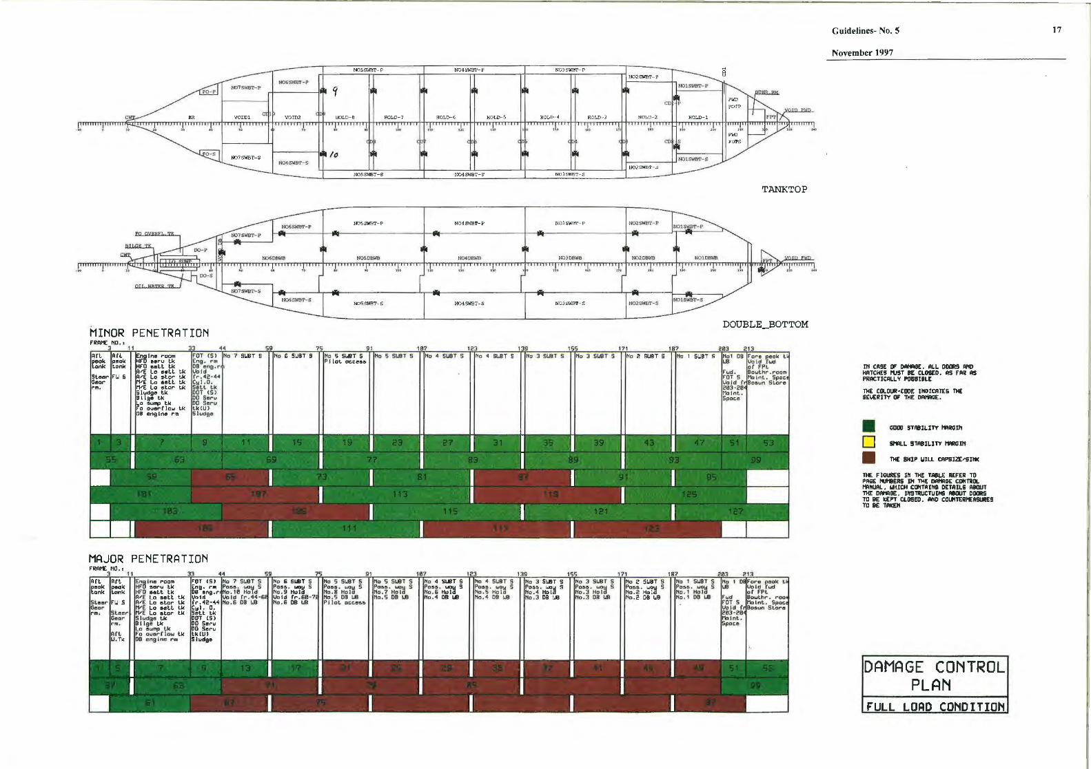
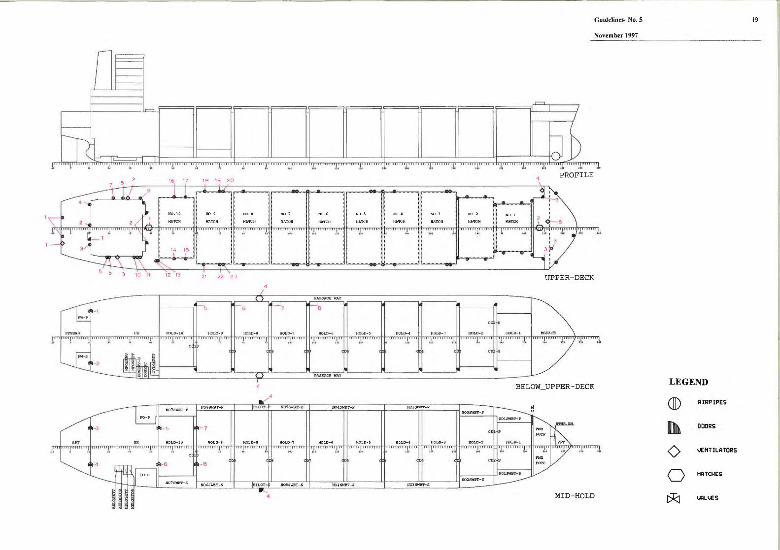
The recommended folillat is shown in Appendix D, and comprises the following:
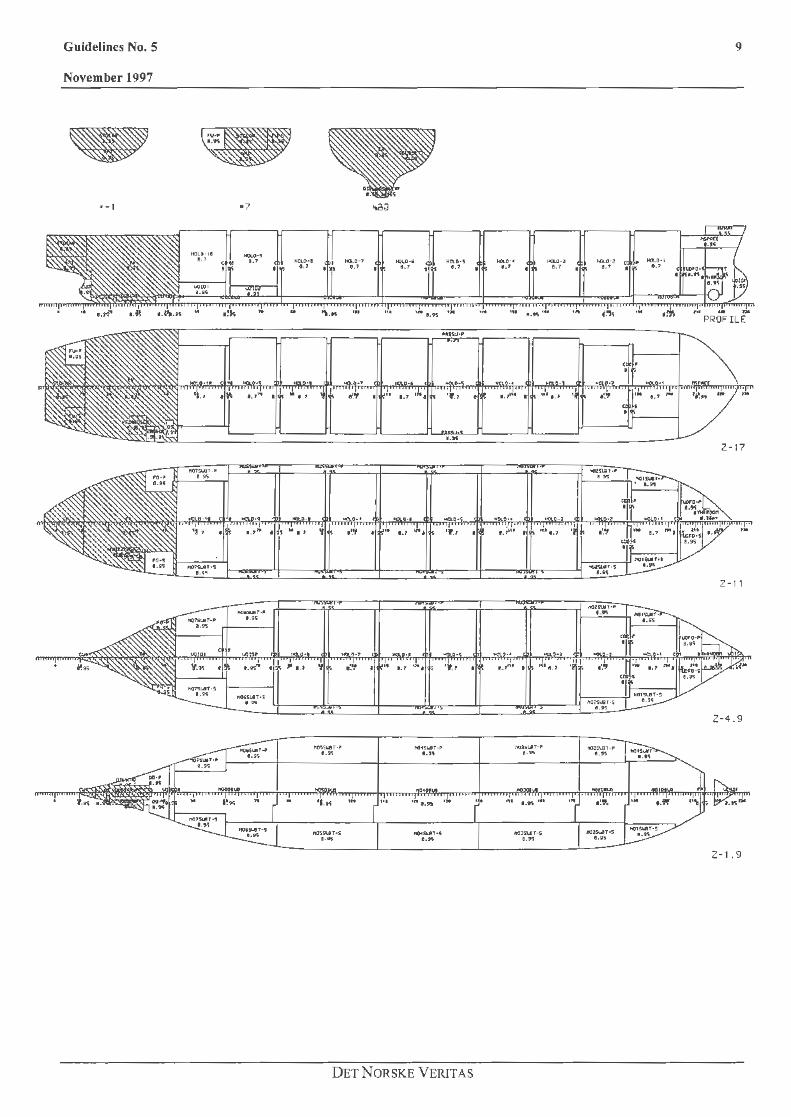
2.1 Watertight subdivision
Plan showing the watertight subdivision for each deck.
2.2 External openings External openings, such as doors, hatches, ventilators and air pipes have been indicated on the drawing. Each opening has been marked with a symbol and a number. The openings are collected and described in the table attached as Appendix C.
lncluded in the description are their positions and their means of closure. Openings which shall maintain the watertight integrity, and which can become submerged in case of damage (See SOLAS Cb. II-1, Part B-1 Reg. 25-10), should be specifically marked.
2.3 Means of closure on internal pipes
The means of closure on internal pipes carried through watertight bulkheads have been marked on the plan. Typically, this may be the ballast water lines, the cargo hold bilge lines and the fuel lines. The valves on such lines would nolillally be kept closed and opened only when needed for operation. Ventilation ducts are in some cases equipped with measures for closing as well.
2.4 Results from damage stability calculations Below the plan showing the watertight boundaries is the plan showing the result of the damage stability calculations. For each compartment and combinations of compartments the ship's capability of surviving the corresponding damage has been indicated by utilising the following colour code:
Guidelines No. 5
November 1997
Green: The ship will survive the asswned S=l damage.
Yellow: The ship may survive the assumed O<S<l damage,but witl1 small margins.
Red: The ship will capsize or sink. S=O
Other symbols or shadowing may be used alternatively.
ln each box used to visualise the extent of damage there is.a number referring to a page in the Damage Control Manual. In the Damage Control Manual further details .on the effect of flooding is given as specified in paragraph 3.
An example Damage Control Plan is shown in Appendix D. It may be found necessary to present several plans in order to visualise the effect of minor/major penetration etc.
2.5 General precautions: (SOLAS Reg. 11-1/23-1, item 3.1)
The general precautions may consist of:
• A list of or reference to a table of external openings that shall be kept closed during navigation. Doors or hatches that may be opened only under the authorisation of the officer of the watch should be noted in particular.
• A 1 ist of or reference to a table of internal openings that shall be kept closed during navigation. Doors or hatches that may be opened only under the authorisation of the officer of the watch should be noted in particular.
• Reference to other documents kept onboard that concerns maintenance ofwatertight/weathertight integrity.
• Means of securing cargo, or reference to other documents available onboard such as the "Cargo Securing Manual".
• Reference to the stability documents.
2.6 Specific precautions: (SOLAS Reg. 11-1/23-1, item 3.2)
The specific precautions may consist of:
• A list of measures in case of damage, such as closing of doors that are used at sea.
• Sounding of alarms • Countenneasures such as cross-flooding or
counterflooding (should not be proposed unless supported by calculations).
DET NORSKE VERlTAS
Guidelines No. 5
November 1997
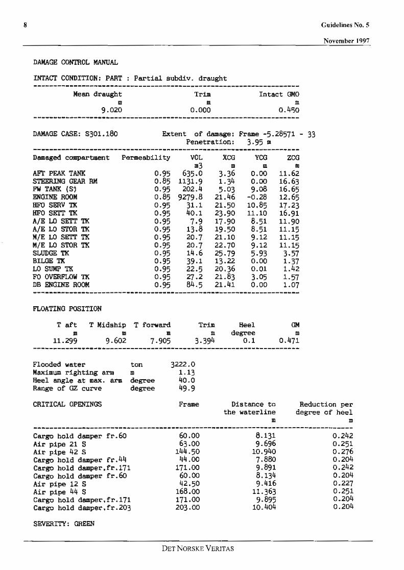
3. Recommended format of the Damage Control Manual Ao extract from the Damage Control Manual is presented in Appendix B. The first pages show the introduction and the description of the information that is contained in the document, together with instructions for use. On the Damage Control Plan, for each box that is used to visualise the extent of damage, there is a number referring to a page in the Damage Control Manual. On the corresponding page in the Damage Control Manual, there is a sketch of the damage case, and a summary of important results such as amount of inflooded water, floating position and critical openings is given.
4. Special consideration for B-60 or B-100 bulk-carriers
5
For a typical B-60 or B-100 bulk carrier, the information listed in the above items is not readily available. The damage stability calculations that are required according to lCLL are carried out at only one draught and for one loading condition, and the ship is required to meet either one (B-60) or twocompartment (B-l 00) damage cases. It is not the intention that the requirements for a Damage Control Information should require additional and extensive damage stability calculations. However, it is important that the conclusions that can be drawn from the damage stability calculations are included as infonnation to the master. In its simplest form this may be a statement such as: "The ship is designed to survive any damage occurring between watertight bulkheads" or "The ship is designed to survive any damage involving any one watertight bulkhead''. It is further recommended to mark each zone with a reference number to the approved damage stability book, in which further details, such as floating position, critical openings etc. can be found. The other items that have been listed above are considered relevant for all vessels.
DET NORSKE VERITAS

6 Guidelines No. 5
November 1997
Appendix A. IMO MSC/Circ.434: "Guidelines for the preparations of the effect of flooding to the master on dry cargo ship"
MSC/Circ.434 13 February 1996
GUlDELINES FOR THE PREPARATION OF INFORMATION ON THE EFFECT OF FLOODING TO BE PROVIDED TO MASTERS OF DRY CARGO SHIPS
I) The Maritime Safety Committe! at its fifty-second session approved the guidelines for the preparation of infonnation on the effect of flooding to be provided to masters of new dry cargo ships as set out in the annex.
2) The guidelines are intended for the use of administrations to the extent they consider necessary.
ANN.EX
GUIDELINES FOR THE PREPARATION OF INFORMATION ON THE EFFECT OF FLOODING TO BE PROVIDED TO MASTERS OF DRY CARGO SHIPS
I) The infonnation provided on the effect of flooding, together with the damage control plan (resolution A.515(13), regulation IJ-1/23- l of the 1974 SOLAS Convention, as amended) and any associated booklet, intends to assist the master in exercising his judgement
2) in cases of serious flooding of the ship. It is not meant to replace his judgement, but to make him aware of the capabilities of the ship.
3) Cases to be investigated and provided in this information should at least include the flooding of the machinery space and each cargo compartment individually. The cases to be investigated for cargo ships with unusual compartmentation may require special consideration.
4) For these investigations the ship should be considered, before floodillg, as floating on an even keel at least for two separate draughts, one of which is to include the summer load line draught. The centre of gravity of the ship (KG) should be taken either from intact stability information or should correspond to the assumed load condition.
5) When considering flooding of the machinery space, a permeability of 0.85 should be used. For flooding of cargo compartments a range of anticipated permeabilities should be applied. These permeabilities need not be lower than 0.60 nor be greater than 0.95.
6) The results of these flooding investigations should be presented in a concise, easily assimilated form for each condition. Critical factors could be presented in tabular fonnat. A description of the assumptions made in compiling the information should also be given.
DETNORSKE VERITAS
Guidelines No. 5 7
November 1997
Appendix B. Extract from the Damage Control Manual
B.1 Introduction
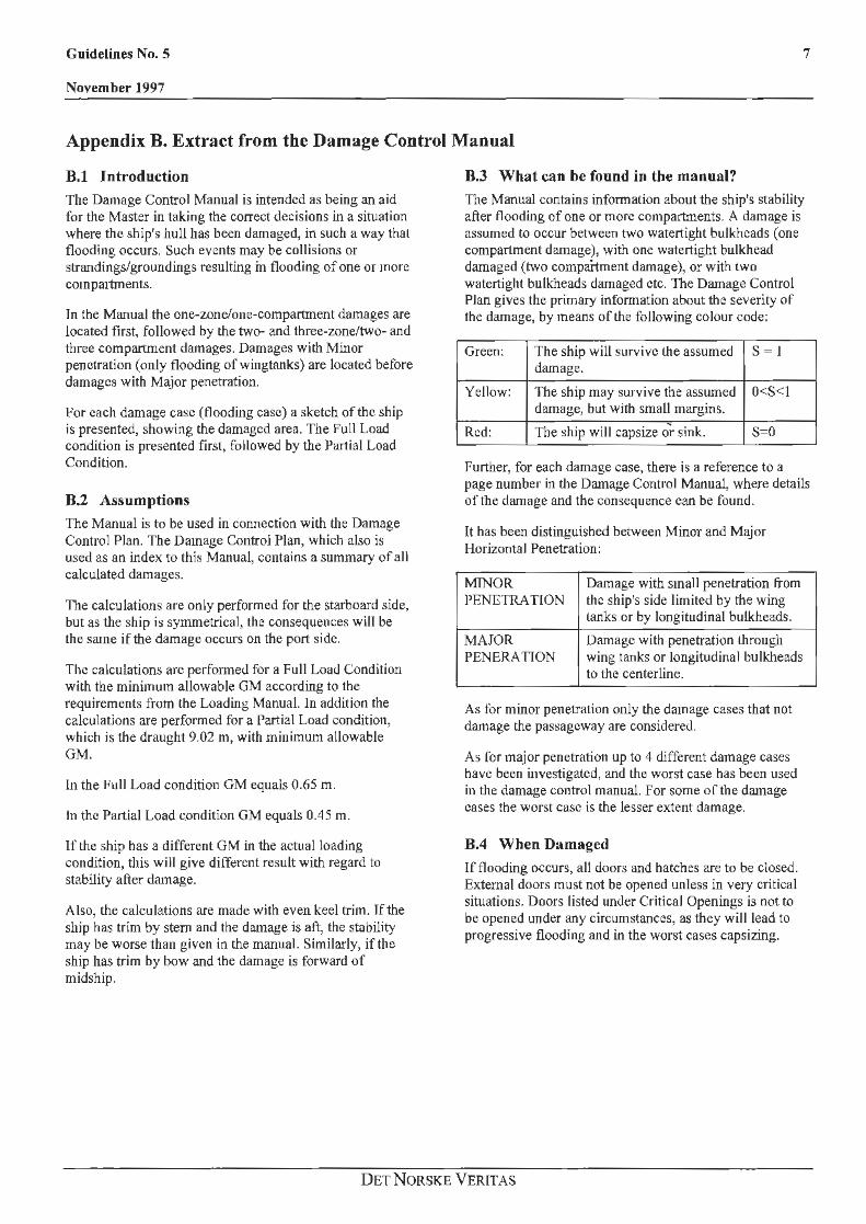
The Damage Control Manual is intended as being an aid for the Master in taking the correct decisions in a situation where the ship's hull has been damaged, in such a way that flooding occurs. Such events may be collisions or strandings/groundings resulting in flooding of one or more compa1tments.
Jn the Manual the one-zone/one-compartment damages are located first, followed by the two- and three-zone/two- and three compartment damages. Damages with Minor penetration (only flooding ofwingtanks) are located before damages with Major penetration.
for each damage case (flooding case) a sketch of the ship is presented, showing the damaged area. The Full Load condition is presented first, followed by the Partial Load Condition.
B.2 Assumptions The Manual is to be used in connection with the Damage Control Plan. The Damage Control Plan , which also is used as an index to this Manual, contains a summary of all calculated damages.
The calculations are only performed for the starboard side, but as the ship is symmetrical, the consequences will be the same if the damage occurs on the port side.
The calculations arc performed for a Full Load Condition with the minimum allowable GM according to the requirements from the Loading Manual. In addition the calculations are performed for a Partial Load condition, which is the draught 9.02 m, with minimum allowable GM.
In the Full Load condition GM equals 0.65 m.
In the Partial Load c.ondition GM equals 0.45 m.
If the ship has a different GM in the actual loading condition, this will give different result with regard to stability after damage.
Also, the calculations are made with even keel trim. Jfthe ship has trim by stem and the damage is aft, the stability may he worse than given in the manual. Similarly, if the ship has trim by bow and the damage is forward of midship.
B.3 What can be found in the manual?
The Manual contains information about the ship's stability after flooding of one or more compartments. A damage is assumed to occur between two watertight bulkheads (one compartment damage), with one watertight bulkhead damaged (two compartment damage), or with two watertight bulkheads damaged etc. The Damage Control Plan gives the primary information about the severity of the damage, by means of the following colour code:
Green: The ship will survive the assumed S = J damage.
Yellow: The ship may survive the assumed O<S<I damage, but with small margins.
Red: The ship will capsize o"'r sink. S=O
Further, for each damage case, there is a reference to a page number in the Damage Control Manual, where details of the damage and the consequence can be found.
It has been distinguished between Minor and Major Horizontal Penetration:
MINOR Damage with small penetration from PENETRA TlON the ship's side limited by the wing
tanks or by longitudinal bulkheads.
MAJOR Damage with penetration through PENERATTON wing tanks or longitudinal bulkheads
to the centerline.
As for minor penetration only the damage cases that not damage the passageway are considered.
As for major penetratio11 up to 4 different damage cases have been investigated, and the worst case has been used in the damage control manual. For some of the damage cases the worst case is the lesser extent damage.
B.4 When Damaged
If flooding occurs, all doors and hatches are to be closed. External doors must not be opened unless in very critical situations. Doors listed under Critical Openings is not to
be opened under any circumstances, as they will lead to progressive flooding and in the worst cases capsizing.
DET NORSKE VERlT AS
8
DAMAGE CONTROL MANUAL
INTACT CONDITION: PART : Partial subdiv. draught
Mean draught m
9.020
Trim m
0.000
Intact GMO m
o.4'50
DAMAGE CASE: S301 . 180 Extent of damage: Frame -5.28571 -Penetration: 3.95 Jl
------------------------------------------------------------------Dam.aged compartment Permeability
AFT PF.AK TANK 0.95 STEERING GEAR RM 0.85 FW TANK (S} 0. 95 ENGINE ROOM 0.85 HFO SERV TK 0.95 HFO SEIT TK 0.95 A/E LO SETr TK 0.95 A/E LO SI'OR TK 0 .95 M/E LO SE'IT TK 0.95 M/E LO STOR TK 0.95 SLUDGE TK 0.95 BILGE TK 0.95 LO SUMP TK 0.95 FO OVERFLOW TK 0.95 DB ENGINE ROOM 0.95
FLOATING POSITION
T aft T Midship T forward m
11.299
Flooded water
m 9.602
Maximum righting arm Heel angle at max . arm Range of GZ curve
Ill
7.905
ton m degree degree
VOL XCG YCO m3 m m
635.0 3.36 0.00 1131.9 1.34 0.00 202.4 5.03 9.08
9279.8 21.46 -0.28 31.1 21.50 10.85 40.1 23.90 11.10 7,9 17.90 8.51
13.8 19.50 8 .51 20.7 21.10 9.12 20.7 22.70 9.12 14.6 25.79 5.93 39.1 13.22 o.oo 22.5 20 . 36 0.01 27.2 21.83 3.05 84.5 21.41 0.00
Trim m
Heel degree
0.1
3222 .0 1.13 40.0 49 .9
3,394
ZCG m
11.62 16.63 16.65 12.65 17.23 16.91 11.90 11.15 11.15 11.15 3.57 1.37 1.42 1.57 1.07
GM m
0.471
Guidelines No. 5
November 1997
33
CRITICAL OPENINGS Frame Distance t o the waterline
Reduction per degree of heel
Cargo hold dam.per fr.60 Air pipe 21 S Air pipe 42 S Cargo hold damper fr.44 Cargo hold damper.fr . 171 Cargo bold damper fr.60 Air pipe 12 S Air pipe 44 S Cargo hold damper,fr.171 Cargo hold damper,fr.203
SEVERITY: GREEN
60. 00 63.00
144 .50 44 .oo
171.00 60 . 00 42.50
168.00 171.00 203 .00
DET NORSKE VERITAS
m
8 . 131 9. 696
10.940 7.880 9.891 8. 134 9. 416
11.363 9.895
10. 404
Ill
0 . 242 0 . 251 0 . 276 0.204 0.242 0. 204 0.227 0 .251 0.204 0.204
Guidelines No. 5 9
November 1997
··""' . ~· •- I
DET N ORSKE V ER£T AS
lO
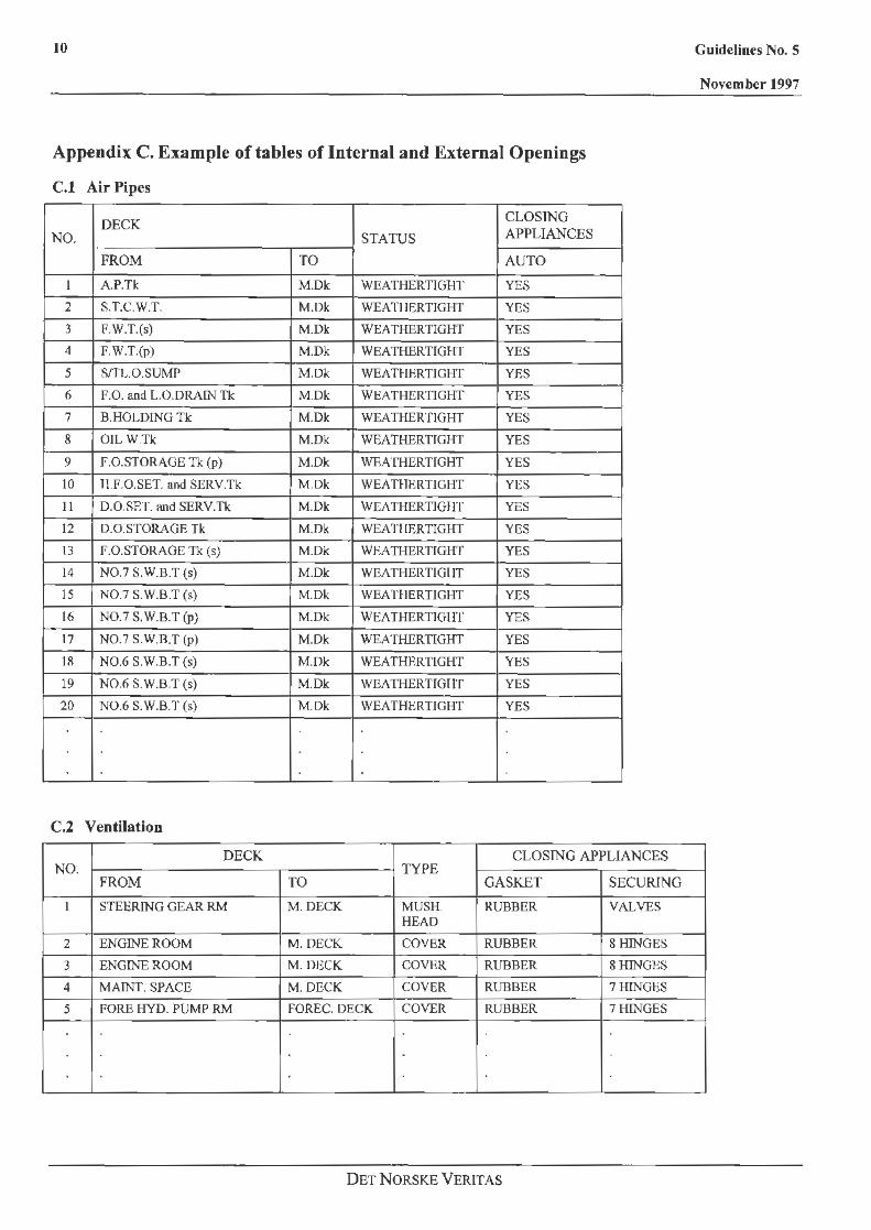
Appendix C. Example of tables of Internal and External Openings
C.1 Air Pipes
DECK CLOSING
NO. STATUS APPLIANCES
FROM TO AUTO
I A.P.Tk M.Dk WEATHERTIGHT YES
2 S.T.C.W.T. M.Dk WEA Tl IERTJGHT YES
3 F.W.T.(s) M.Dk WEATHER TIGHT YES
4 F.W.T.(p) M.Dk WEATHERTIGHT YES
5 S/TL.O.SUMP M.Dk WEATHERTIGHT YES
6 F.O. and LO.DRAIN Tk M.Dk WEATHERTIGHT YES
7 B.HOLDING Tk M.Dk WEATHERflGHT YES
8 OIL W.Tk M.Dk WEATHERTIGHT YES
9 F.O.STORAGE Tk (p) M.Dk WEATHER TIGHT YES
10 ll.F.0.SET. and SERV.Tk M.Dk WEA TIJERTIGHT YES
11 0.0.SET. and SERV.Tk M.Dk WEA THERTIGf IT YES
12 D.O.STORAOR Tk M.Dk WEA Tl IF,RTIGHT YES
13 F.O.STORAOE Tk (s) M.Dk WEATHERTIGHT YES
14 N0.7 S.W.B.T (s) M.Dk WEATHERTIGIIT YES
15 N0 .7 S.W.B.T (s) M.Dk WEAHIERTIGHT YES
16 N0.7 S.W.B.T (p) M.Dk WEATHERTJGIIT YES
17 N0.7 S.W.B.T (p) M.Dk WEATHERTIGHT YES
1R N0.6 S.W.B.T (s) M.Dk WEATHRRTIGHT YES
19 N0.6 S.W.B.T(s) M.Dk WEATHERTIGTIT YES
20 N0.6 S.W.B.T (s) M.Dk WEATHERTIGHT YES
C.2 Ventilation
DECK CLOSING APPLIANCES NO. TYPE
FROM TO GASKET SECURING
I STEERING GEAR RM M.DECK MUSH. RUBBER VALVES HEAD
2 ENGINE ROOM M.DECK COVER RUBBER 8HJNGES
3 ENGINE ROOM M. DECK COVER RUBBER 8 HINGES
4 MAINT. SPACE M.DECK COVER RUBBER 7 HINGES
5 FORE HYO. PUMP RM FOREC. DECK COVER RUBBER 7 HINGES
DET NORSKE VERIT AS
Guidelines No. S
November 1997

Guidelines No. S 11
November 1997
C.3 Doors
LOCATION NO. DESCRIPTION TIGHTNESS TYPE
DECK Fr. No. PIS OPENING STATUS
1 A COMM. WEATHER TIGHT HINGED MAIN Dk 11 s #1
2 A COMM. WEATHER TIGHT HINGED MAIN Dk 38 PIS #1
3 MAINT. SPACE WEATHER TIGHT HINGED MAIN Dk 210 PIS #1
4 PILOT DOOR WATER TIGHT HINGED Below MAIN Dk 87 PIS #2
5 CARGO HOLD WATER TIGHT HINGED Below Upp. Dk 60 P/S #2
6 CARGO HOLD WATER TIGHT HINGED 13elow Upp. Dk 76 PIS #2
#I To be kept closed during navigation.
#2 May be opened only under the authorization of the officer of the watch.
C.4 Valves
LOCATION NO. DESCRIPTION TYPE
Fr. No. PIS
l F.W.Tk (p) SELF CLOSING V N 1 1 PIS
2 F.W.Tk (S) SELF CLOSING V N 11 PIS
3 A.P.Tk. GATE NON-RETURN VIV 11 p
4 A.P.Tk. GA TE NON-RETIJRN VN 11 s 5 NO. 10 CARGO HOLD BIW REMOTEVN 44 p
6 NO. IO CARGO HOLD BIW REMOTE VIV 44 s 7 NO. 9 CARGO HOLD BIW REMOTEVN 60 p
8 NO. 9 CARGO HOLD B/W REMOTE VIV 60 s 9 NO. 8 CARGO HOLD B/W REMOTE VIV 76 p
JO NO. 8 CARGO HOLD BIW REMOTE VIV 76 s
C.5 Small Hatches
LOCATION NO. DESCRIPTION TIGHTNESS
DECK Fr. No. P/S
1 AFT HATCH WATER TIGHT MAINDk 39 -2 FOREHJ\TCH WATER TIGHT FORECASTLE Ok 208 -3 ROPE HATCH WEATHER TIGIIT FORECASTI..E Dk 214 s 4 PASSAGE WAY WATER TIGHT Below UPP. Dk 87 PIS
DET NORSKE V ERIT AS

12
D ETNORSKE VERITAS
Guidelines No. 5
November 199'7
Guidelines- No. 5
November 1997
Appendix D. Recommended layout of the Damage Control Plan
DET NORSKE VERITAS
13
14
D ETNORSKE VERITAS
Guidelines No. 5
November 1997

MINOR PENETRATION FRAK: HO.:
3 11 Arl Att.
r:~~ r:~~ St.oar FU 5 Gear rm.
33 44 r:or IS) Ho ? St.BT s Eng. rm ~ 1 :n9.r fr,42·44 C!jl.O. Satt t.I< DOT (Sl DO Ser11 DO Scru Lk<Ul Sludge
MAJOR PENETRATION rRAl"E: N(I.:
3 11 33 Art. Art. ~r8 1~: .. ~0~~ ror <S> No 7 Sl.81 S ~eol< reok Eng. rm ~~~~a tfc:Vd
5 onl< onk HF'O •at.t. t.k
59 ?5 91 No 6 SIJBT S Ho S SW8T S No S SI.ST S
PI lot. crc.c:.c:oo
91 No 6 SI.Jin S No S Sl.8T S No 5 SI.BT S
~~~~·H~M s ~~~;·H:l~ S ~~~~· .. ~~ s 11<'£ Lo i!Ot.t tk
08 ang.r Vold Uo Id fr. 44·61 Uold fr .jl0· 7E No.S DB t.8 No. 5 DB t.s
St.oor ru s A/E Lo at.er t.k lr.42·'\4 Ho.6 OB !.8 No.6 08 l.B p J I Ot ac.c.C:!>S Gcor- rvE LQ eet.t. t.k ~~li ~k rm. Steer !VE Lo &lor tk
Geel" Sludge t.k DOT (SI rm. Bilge tk DO Seru
Lo OU"'f) tk DO Serv
C't. f'o overt low t.k LklU) .Tk DB engine rM Slud9e1
I I I I I I
II ,_,
10? 123 139 ISS 171
Ho 4 5"8T S Ho 4 51.JST S No 3 StJ8T S Ho 3 SIJBT 5 No 2 SIJST S
10? 123 139 1SS 1?1 Ho 4 SI.BT S No 4 St.eT S No 3 51.eT S No 3 51.8T S No 2 SUST S
~~~S·H~~ S Poe~ . wciy S ~~~~·H~~ 5 ~~~~·H~M 5 ~~~L~::l~ s Ho.<; Hold
No.4 DB L8 No.'< Dli W8 No.3 OB UB No.3 08 1.8 No.2 08 I.IS
I I I I I ,_, I I I
TANK TOP
DOUBLE_BOTTOM
8? 203 213 No SIJ8T 5 Nol OB Fora peol< ~·
18? Ho 1 Sl.JBT S
~~~~·H::~ S No. 1 08 1.8
I
I
IJB Uo Id fwd
Fwd. F'OT S Uold r 203· <?0 Molnt. Space
of FPt. Bowl.hr.room Mo l nt.. Spec 8oeun Store
203 213 No I DE~l~ ~~k ti UB or F'Pt. rwct Bowt.hr. roo• l'OT s Uofd r. Mo lnt . Spoc•
Booun Store 203 -20 Molnt.. Spece
-
Guidelines- No. 5
November 1997
I/f CA!l£ OF 1)#1'16£. ALL DO()jtS AllD HATCHES 11JST 8£ C~OSED, AB rAR AS PAllCTJCALLY POSSISl.E
THt COl.OLJR•COOE llll>ICArtS THE SEVEIUTY or 'mE OAHAGE.
• GOOD STilHLITY HARGllf
1::::1 SHALL STAtILJTY MllRGIH
• THE SHIP WIU. CAPSl2t/6JHK
THE FJGUllE11 lit THE TABLE llEF'£A TD PAGE llU111EA9 Itl THE DA>#:IGC COllTROL l'WIUAL. I.MICH cotmUN!i DETAILS ABOUT THE DAMAG£, JllS'lllUCTUIHS AllOOT DOORS TD 8E ICEPT Cl..OSED. lVfD COU!ft£Al'l:A!lllAE6 TO 8E TAJ(£11
DAMAGE CONTROL PLAN
PART LOAD CONDITION
15
MINOR PENETRATION Fli'Rl'C ND . 1
3 IHI. Arl
r:~~ ~~~~ Stear FUS G"or ~m.
FOT <S > Ho 7 SI.el S Erig. rm
lk ~l~n9.r tk rr.42- 44
t~ ~~li0i.1< DOT IS> OD Se ru 00 Se rv tklU> S l udge
MAJOR PENETRATION FRAl'C HO. 1
3 11 33 44 AFI. RH ~f!8 1~:r:0~k FOT <S> Ho 7 SUIT S eeok e•ok En9. ,.,. ~~~fe ::Yd
5 onk onk
59 75 9 1
!9
Ho 6 SWBT S Ho 5 Sl8T 5 No 5 SUIT S p I lot. OC.C.066
75 91 Mo Ii SUBT S Mo 5 Sl.ST S Ho 5 SUIT S
~~~~·H~M 5 ~~~~·H~M 5 ~~~~-H~M 5 WO set.t ti< A/E Lo eelt t k e:s:"B·"' Vo Id fr-.44-61 Vo ld fr- . 68-71 Ho,5 OB UI Ho. 5 DB 1.8
51.oer- Fu S R/E Lo et.or- tk fr.42-44 Ho.6 DO lJ8 Ho.6 DB 1..8 Pl lot. DCC.II&& Gear 11/E Lo Hlt. t.k C11 I . O. ,..,, Steer- l'VE Lo e I.or tk Solt tk
Gear Sludga tk DOT CS) rm. Bl lge t.k DD Ser-11
Lo "UfftP tk DD Ser-11 Art. Fa ouarf low t k l.lllU) U.Tk DB engine rm Sl udge
I I I I I I
II I I
187 Mo 4 SLIH S
107 Ho 4 SI.ST S
~~~~ -H~M 5
Ho.4 OB L8
I I
123 139 155 171 Ho 4 SLJ8T 5 Mo J suns Ho 3 SI.ST S Ho I! SIJ9T S
123 139 155 171 Ho 4 Sl.'9T S Mo 3 SLIH S Ho 3 St.ST S Ho 2 Sl.8T S
~~~~-H~~M 5 ~~~~-H~M 5 ~~~~-H~M 5 ~~~~-H~~ S Ho. 4 DO lJ8 Ho.3 OB I.II Ho.3 OB lJ8 Ho.e DB 1.19
I I I I I I
I I
TANKTOP
DOUBLE_BOTTOM
187 203 213 Ho 1 SWBT S Hal DB Fore peak t
t..8 Vo Id ti.id
187 Ho 1 SUBT S
~~~~ -H~M 5
Ho. 1 DB lJ8
I
I
Fwd. FOT 5 Va Id r 203-20 Molnl. Space
or FPL Bowlhr-.r-oom Molnt. Spoc Bo11un SLoro
203 213 Ho I OE Faro f>OOk ti 1.8 Vo Id ti.id
or FPt. Fi.id Bowl.hr-. roo• FOT S Mo Int. Spoc1 Vold r. Bo11un Stor-o 283 -20 Molnt.. Space
-
Guidelines- No. 5
November 1997
rH CA9£ OF' 0NNE . ALL Ooat!I AM> HATCHES ltl9T 8E CLOSED. RS FAil AS PRACTICALLY P069I8LE
TM£ CG.DL.R•CDOE Jlfl>ICRTE6 THE 9EIA:IUTY OF THE DR~E.
• GDDD STABJUTY ~th [::J St!ALL STABILITY ~I" • THE SHIP LllU. CAPBIZE"Sltte
1l£ F !GUii£$ l~ THE TAfl.,E RlFEll TO P~ IU'eEA& II! TWf; ~GE Catt'fllOL ~!!URL , llUCff CIJITlUltS DETAILS RIOIJT TI.: DAHA8£ • 1119 TltUCTU lH!I AIOUT ooms TD llE 1C£ PT CLOSED • NII) CO~TE111'£llSUIE9 TD It TAICEM
DAMAGE CONTROL PLAN
FULL LOAD COMDITIOM
17
2
3 10 11
f'O-P
(fr ...
16 17
N0.10
15
12 1'3
N07SWBT-P
5
HOLD-10 l l llf(l iirTTII
"
18 19 20
N0.9 H0.8 N0.7 N0.6 NO.S
21 22 21
4
4
ll06SWBT-P PILOT- NOSSWBT-P N04SWBT-P
-e D D D
PIL<n'- N05SWBT-S ----·.::-~ ____ ...._ ______ _
4
Guidelines- No. 5 19
November 1997
4 PROFILE
N0.4 NO.~ N0.2 N0.1
UPPER-DECK
BELOW_UPPER-DECK LEGEND
1103SWBT-P CID AIRPIPES
• DOORS
HOLD-3 rm,-rnnrrrri
?'O H'O <> \JENTILATORS
0 HATCHES
MID-HOLD r9<l VAL\JES