recommendations room hmi
TRANSCRIPT


Recommendations for Cargo Control
Room HMI
First published in 2021 by Witherby Publishing
ISBN: 978-1-85609-996-7 eBook ISBN: 978-1-85609-997-4
© Copyright of SIGTTO, Bermuda
The Society of International Gas Tanker and Terminal Operators (SIGTTO) is a non-profit making organisation dedicated to protect and promote the mutual interests of its members in matters related to the safe and reliable operation of gas tankers and terminals within a sound environment. The Society was founded in 1979 and was granted consultative status at IMO in November 1983.
www.sigtto.org
Notice of Terms of Use
While the information and advice given in this document (Recommendations for Cargo Control Room HMI, 2021) has been developed using the best information currently available, it is intended purely as guidance to be used at the user’s own risk. No warranties or representations are given nor is any duty of care or responsibility accepted by The Society of International Gas Tanker and Terminal Operators (SIGTTO), the members or employees of SIGTTO, or by any person, firm, company or organisation who or which has been in any way concerned with the furnishing of information or data, the compilation or any translation, publishing, supply or sale of the document, for the accuracy of any information or advice in the document or any omission from the document or for any consequence whatsoever resulting directly or indirectly from compliance with, adoption of, or reliance on guidance contained in the document even if caused by failure to exercise reasonable care.
Published by
Witherby Publishing Group Ltd Navigation House, 3 Almondvale Business Park, Almondvale Way, Livingston EH54 6GA, Scotland, UK
+44 (0)1506 463 [email protected]
Cover image courtesy of Kongsberg Maritime AS

iv
Contents
Part – 1 Introduction ............................................................................................................................................. 11. Introduction ..................................................................................................................................... 32. Scope ............................................................................................................................................. 33. Introduction to Cargo Control Room HMI Design ................................................................................ 34. Key Publications .............................................................................................................................. 4
Part – 2 Recommendations .................................................................................................................................... 55. HMI Design Process ......................................................................................................................... 76. Further Guidance .......................................................................................................................... 28
Annexes ............................................................................................................................................................. 33Annex 1 – Glossary of Terms and Abbreviations ....................................................................................... 35Annex 2 – Reference List ......................................................................................................................... 36

Part – 1
Introduction


3
Introduction
1. Introduction
This document recommends the application of ergonomic design principles to the human-machine interface (HMI) in cargo control rooms (CCRs) on gas carriers. The effective design of displays enhances the usability of systems and equipment. It reduces human error, enhances situational awareness and supports safe and effective monitoring and control under normal and abnormal modes of operation.
This document builds on Recommendations for Designing Cargo Control Rooms1, which recommends a human-centred approach to the design of CCRs. This includes defining the operational philosophy, role requirements and operational tasks to facilitate a clear understanding of the information and control functions required by the operator for each task. Recommendations for Cargo Control Room HMI builds on this understanding and recommends a design process that ensures the HMI supports the operator, allowing safe and effective operation of the system.
It is recommended that ship owners work with system designers, Classification Societies and shipyards to create an HMI that clearly presents the appropriate information and control functions. This allows the operational philosophy to be safely implemented in the development of the CCR. The information in this document is based on established standards, such as ISO 11064 2.
Part 1 of this document provides a general introduction to this topic. Part 2 details the recommended design process steps for the HMI and provides further guidance for screen-based gas carrier CCR design.
2. Scope
This document provides guidance for all types of liquefied gas carriers. These recommendations are prepared for and apply only to new ships. They do not apply to existing ships and there is no expectation that existing ships should be altered.
Where significant retrofit or upgrade projects are being planned for existing liquefied gas carriers, these recommendations may provide helpful guidance if the design of the HMI is revisited.
3. Introduction to Cargo Control Room HMI Design
While drawing on several sources, this document focuses on ISO 11064-5 3. This covers the principles and processes to be adopted when designing the HMI of a control station. These should ensure that the use of controls and displays in the CCR is as reliable, safe, comfortable and efficient as possible.
ISO 11064-5 introduces standards and recommendations for:
� Selecting the appropriate display and control types
� structuring and presenting information on screens and shared off workstation displays
� establishing control and dialogue procedures.
1 SIGTTO – Recommendations for Designing Cargo Control Rooms (Reference 1)2 ISO 11064 – Ergonomic design of control centres (Reference 2)3 ISO 11064 – Ergonomic design of control centres – Part 5: Displays and controls (Reference 2)
4
Introduction
ISO 9241-110 4 explains how applying ergonomic principles to the HMI aims to satisfy the following principles of effective interaction between the user and the system:
� Suitability for the user’s tasks: the operating functions and the user-system interactions are based on thetask’s characteristics, as defined through task analysis5
� self-descriptiveness: the control system presents appropriate information, when and where it is beneficialto the user, to make its capabilities and use immediately obvious without the need for avoidable user-system interactions
� conformity with user expectations: the control system’s behaviour is predictable based on the context ofuse and commonly accepted conventions
� learnability: the control system supports discovery of its capabilities and how to use it, allows explorationof the control system, minimises the need for learning and provides support, including self-help guides,when learning is needed
� user tolerance (robustness): the control system assists the user in avoiding errors and, in case ofidentifiable errors, assists the user to recover from errors.
4. Key Publications
This document is intended as a starting point and cannot, and does not attempt to, address all areas of CCR HMI ergonomics and design. There are many useful publications that should be considered, including:
� ISO 11064 – Ergonomic design of control centres (Reference 2)
� ISO 9241 – Ergonomics of human-system interaction — Part 220: Processes for enabling, executing andassessing human-centred design within organizations (Reference 3)
� ISO 26800 – Ergonomics — General approach, principles and concepts (Reference 4).
4 ISO 9241 – Ergonomics of human-system interaction – Part 110: Interaction principles (Reference 3)5 See SIGTTO – Recommendations for Designing Cargo Control Rooms (Reference 1)

Part – 2
Recommendations


7
Recommendations
5. HMI Design Process
This document recommends a six-step process for designing the HMI. This is a slightly modified version of the seven-step display and control specification process laid out in ISO 11064 6. In this modified version, shown in Figure 1, Steps 3 and 4 from ISO 11064 have been merged.
Ship owners should provide detailed information, based on task analysis, in the specification for the HMI. This will give significant input to Steps 1, 2 and 3, the main focus of these recommendations. The system designer can then take the design forward, building and testing initial concepts through to the detailed design and verification stages.
The design process should take account of earlier decisions made using Recommendations for Designing Cargo Control Rooms7. These involve task synthesis, role identification, workstation numbers, information and control functions for each task. Although the development of the control interfaces should be based on these decisions, it may be necessary to revisit original assumptions as the detailed design of the control and display interface develops.
Step 1 – Information �ow analysis between operator andsystem
Step 2 – Develop general approach to interface design:prepare outline project guidelines
Task analysis
Workload estimates
General principles
Standards
Operational scenariosFunctional requirementsUsers
ISO 11064-78
Step 3 – Development, prototyping and testing of initialinterface concepts
Step 4 – Finalise project guidelines on interface design
Step 5 – Detailed design of control and display interface
Step 6 – Veri�cation and validation
Task synthesis
8Figure 1: HMI design process, based on ISO 11064 9
6 ISO 11064 – Ergonomic design of control centres (Reference 2)7 SIGTTO – Recommendations for Designing Cargo Control Rooms (Reference 1)8 ISO 11064 – Ergonomic design of control centres – Part 7: Principles for the evaluation of control centres (Reference 2)9 ISO 11064 – Ergonomic design of control centres (Reference 2)

8
Recommendations
5.1 Step 1 – Information Flow Analysis Between Operator and System
Step 1 focuses on the information flow necessary to undertake the control tasks, based on the operational philosophy and task synthesis. Task synthesis involves the identification and allocation of tasks, including their required information and control functions.
This step should use task synthesis, role identification, workstation numbers, relevant information and control functions for each task, as identified using Recommendations for Designing Cargo Control Rooms10. For this step, detailed methods of presentation and possible options for technology are not considered.
The following questions should be addressed in this step:
� Has the context of use for each intended or actual user group been described in a suitable format andsufficient detail for later use? This could include user needs analysis, user requirements specification andevaluation
� have the needs related to aspects of user experience been identified? This should include, whereappropriate:
� organisational impacts
� online help
� user documentation
� training
� maintenance and support
� long-term use
� the user’s aesthetic experience of the physical design
� have relevant stakeholders, such as representative users, subject matter experts and managers, beenconsulted to obtain a representative and complete set of user needs, including those derived fromorganisational and management needs?
� has each user need been stated as an outcome to be achieved by the user (what needs to be achieved,rather than how) and the circumstances in which users have these needs?
5.2 Step 2 – Develop a General Approach to the Interface Design
In this step, the overall framework for the design of the control display is developed. This process is used to scope the project guidelines for the interfaces that will be developed in Step 4. This step will list the main topics to be covered.
ISO 11064-5 11 covers the principles for the ergonomic design of the HMI. They are grouped into:
� General principles
� display-related principles
� control and interaction-related principles.
10 SIGTTO – Recommendations for Designing Cargo Control Rooms (Reference 1)11 ISO 11064 – Ergonomic design of control centres – Part 5: Displays and controls (Reference 2)

9
Recommendations
These principles are common to many applications of ergonomics but have been selected for their particular relevance to control room design. They are ordered so that they begin with wider considerations and move on to more specific considerations.
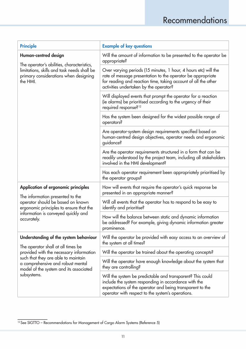
Drawing on ISO 11064, the principles considered most relevant to the design of the CCR HMI on gas carriers are listed in the first column of Table 1. The second column contains examples of key questions to consider when specifying the requirements of the HMI for each task and subtask identified in Step 1.
In addition to the principles in Table 1, the following high-level aspects should be considered:
� Has the harm that can result from poorly considered human-centred design for the users, organisationand project been assessed?
� have the potential system health and safety hazards, such as fatigue, eye strain and mental stress, beenassessed, including specific software-related risks?
� have potential conflicts between human-centred design and other design attributes been resolved?
� have project resources been provided? This includes involvement of a sufficiently representative range ofusers, needed to mitigate risks to achieve the required human-centred design.
Principle Example of key questions
Efficient HMI
The HMI shall support the operator to complete their activities efficiently and effectively.
How will the operator be presented with only the information relevant to the task?
How will tasks that can be automated easily and safely be allocated to the system and the process be made transparent to the operator?
Will recurrent tasks be executed by easily repeatable sequences?
How will closed circuit television (CCTV) images be presented in accordance with operator requirements, such as use of split screens?
How will available help, such as manuals, be integrated into the system?
How will the process for performing infrequent tasks be made self-explanatory or supported by help information?
10
Recommendations
Principle Example of key questions
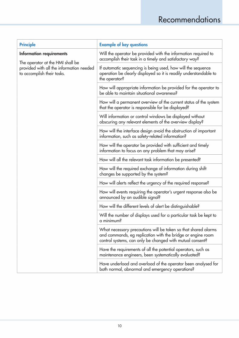
Information requirements
The operator at the HMI shall be provided with all the information needed to accomplish their tasks.
Will the operator be provided with the information required to accomplish their task in a timely and satisfactory way?
If automatic sequencing is being used, how will the sequence operation be clearly displayed so it is readily understandable to the operator?
How will appropriate information be provided for the operator to be able to maintain situational awareness?
How will a permanent overview of the current status of the system that the operator is responsible for be displayed?
Will information or control windows be displayed without obscuring any relevant elements of the overview display?
How will the interface design avoid the obstruction of important information, such as safety-related information?
How will the operator be provided with sufficient and timely information to focus on any problem that may arise?
How will all the relevant task information be presented?
How will the required exchange of information during shift changes be supported by the system?
How will alerts reflect the urgency of the required response?
How will events requiring the operator’s urgent response also be announced by an audible signal?
How will the different levels of alert be distinguishable?
Will the number of displays used for a particular task be kept to a minimum?
What necessary precautions will be taken so that shared alarms and commands, eg replication with the bridge or engine room control systems, can only be changed with mutual consent?
Have the requirements of all the potential operators, such as maintenance engineers, been systematically evaluated?
Have underload and overload of the operator been analysed for both normal, abnormal and emergency operations?
11
Recommendations
Principle Example of key questions
Human-centred design
The operator’s abilities, characteristics, limitations, skills and task needs shall be primary considerations when designing the HMI.
Will the amount of information to be presented to the operator be appropriate?
Over varying periods (15 minutes, 1 hour, 4 hours etc) will the rate of message presentation to the operator be appropriate for reading and reaction time, taking account of all the other activities undertaken by the operator?
Will displayed events that prompt the operator for a reaction (ie alarms) be prioritised according to the urgency of their required response? 12
Has the system been designed for the widest possible range of operators?
Are operator-system design requirements specified based on human-centred design objectives, operator needs and ergonomic guidance?
Are the operator requirements structured in a form that can be readily understood by the project team, including all stakeholders involved in the HMI development?
Has each operator requirement been appropriately prioritised by the operator groups?
Application of ergonomic principles
The information presented to the operator should be based on known ergonomic principles to ensure that the information is conveyed quickly and accurately.
How will events that require the operator’s quick response be presented in an appropriate manner?
Will all events that the operator has to respond to be easy to identify and prioritise?
How will the balance between static and dynamic information be addressed? For example, giving dynamic information greater prominence.
Understanding of the system behaviour
The operator shall at all times be provided with the necessary information such that they are able to maintain a comprehensive and robust mental model of the system and its associated subsystems.
Will the operator be provided with easy access to an overview of the system at all times?
Will the operator be trained about the operating concepts?
Will the operator have enough knowledge about the system that they are controlling?
Will the system be predictable and transparent? This could include the system responding in accordance with the expectations of the operator and being transparent to the operator with respect to the system’s operations.
12 See SIGTTO – Recommendations for Management of Cargo Alarm Systems (Reference 5)

12
Recommendations
Principle Example of key questions
Avoid hidden information (flying blind)
The objects under control shall always be displayed.
Have system commands that might have serious adverse consequences been identified and mitigated by requiring confirmation before execution?
Has adequate consideration been given to the recording and handover of information that is not typically on the system and how it is collated?
Simplicity
Human-machine interaction should be kept simple through the application of a minimum number of rules.
Have emergency situations been identified and the required interactions made appropriately simple?
Operator support
The system should aid the operator in inputting information efficiently and correctly so that the risk of errors is minimised.
Have the possible operational operator errors that should be checked automatically been identified, such as high-level alarm override timers?
Have the inputs and tasks which should be plausibility checked, ie obviously wrong, been identified (units, rates etc)?
Feedback
Appropriate feedback shall be provided to the operator at all times.
Have the circumstances where adverse consequences may result from the operator’s action been identified and configured to provide appropriate feedback, such as system requests confirmation?
Error tolerance
The system shall take account of the fact that the operator will make errors and should minimise their effects.
Has each task where safeguards are needed been identified?
Table 1: Principles for the ergonomic design of the CCR HMI, based on ISO 1106413
13 ISO 11064 – Ergonomic design of control centres (Reference 2)

13
Recommendations
5.2.1 Example application of principles and key questions
Taking the tasks identified in Step 1 using Recommendations for Designing Cargo Control Rooms 14, key questions should be answered in the context of each task and subtask.
The high-level task definition for loading is shown as an example in Figure 2.
14 SIGTTO – Recommendations for Designing Cargo Control Rooms (Reference 1)

14
Recommendations
Task requiringinformation only
De�ne taskrequirements Loading
Gassing up
Preparing
New build
Loadedpassage
Gas trials
Emergencyprocedures
Troubleshooting
Regasi�cation
Preparation fordry dock
Ship to shiptransfer
Ballastpassage
Discharge
Cool down
Completion
Start
Monitoring
Line up
Disconnection
Levels and rates
Valveposition
Pressure
Ballaststatus
Trim
List
High duty compressor status
Alarms
Communication
Reliquefaction
Display
Control Method ofcontrol
Mimic
Controller
List images
Valve location
Local
Remote
Auto
High-level tasks
Task requiring bothinformation and control
Figure 2: Example of a simplified range of high-level tasks, from Recommendations for Designing Cargo Control Rooms

15
Recommendations
Task requiringinformation only
De�ne taskrequirements Loading
Gassing up
Preparing
New build
Loadedpassage
Gas trials
Emergencyprocedures
Troubleshooting
Regasi�cation
Preparation fordry dock
Ship to shiptransfer
Ballastpassage
Discharge
Cool down
Completion
Start
Monitoring
Line up
Disconnection
Levels and rates
Valveposition
Pressure
Ballaststatus
Trim
List
High duty compressor status
Alarms
Communication
Reliquefaction
Display
Control Method ofcontrol
Mimic
Controller
List images
Valve location
Local
Remote
Auto
High-level tasks
Task requiring bothinformation and control
Figure 2: Example of a simplified range of high-level tasks, from Recommendations for Designing Cargo Control Rooms

16
Recommendations
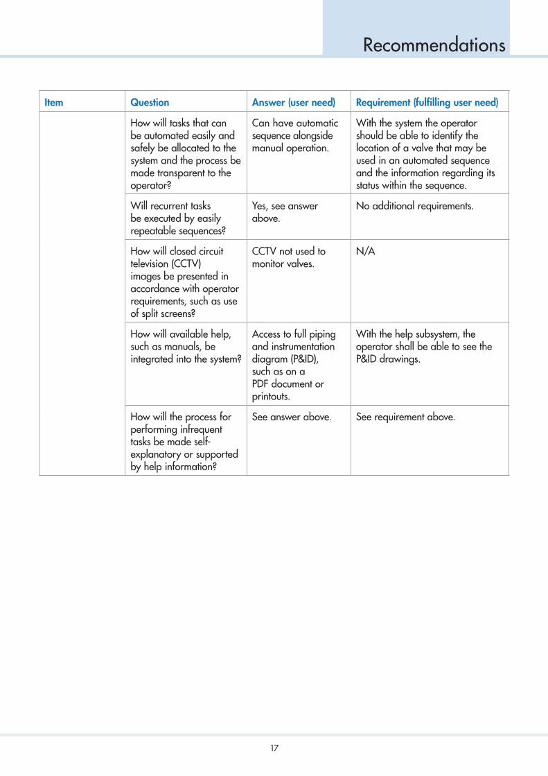
To illustrate how the questions from Table 1 may be applied, Table 2 shows potential answers to the questions from the operator’s perspective, ie the user need. It then shows how they may translate into requirements that should be specified to fulfil the user need.
In Table 2 the process is started at the lowest level and repeated, working up the hierarchy of levels. In this example not all tasks have been shown, only valve location, display, control and valve position have been selected to demonstrate the method. Not all questions will be relevant for all tasks, and in this example this is simply noted as not applicable (N/A).
Progressing up the hierarchy, it may be evident that the question has been addressed at the level below and this is noted as ‘see lower level’. When analysing the full scope of the HMI, all questions should be applied to all tasks and subtasks.
For further guidance on how to write user requirement specifications, see ISO 25065 15.
Item Question Answer (user need) Requirement (fulfilling user need)
Valve location
Physical and logical location of the valves used in the context of the task being analysed, ie completion.
How will the operator be presented with only the information relevant to the task?
To be able to see logical links between elements relevant to the operation, such as emergency shutdown (ESD) and pressure.
With the system the operator shall be able to access information on the location and logical control links of the valves.
View only specific symbols relevant to the task.
With the help subsystem, the operator shall be able to view a key to the symbols used. The owner’s symbol guide or international standards could be referenced here.
With the system the operator shall be able to see the status, position and type of each valve.
With the system the operator shall be able to see only the valves used during completion.
Access to more detailed information, such as set points, alarms, system limitations and time delays.
With the system the operator shall be able to see information on valve set points, alarms, system limitations and time delays.
With the system the operator shall be able to access this information within two clicks.
15 ISO 25065 – Systems and software engineering – Software product Quality Requirements and Evaluation (SQuaRE) – Common Industry Format (CIF) for Usability: User requirements specification (Reference 6)
17
Recommendations
Item Question Answer (user need) Requirement (fulfilling user need)
How will tasks that can be automated easily and safely be allocated to the system and the process be made transparent to the operator?
Can have automatic sequence alongside manual operation.
With the system the operator should be able to identify the location of a valve that may be used in an automated sequence and the information regarding its status within the sequence.
Will recurrent tasks be executed by easily repeatable sequences?
Yes, see answer above.
No additional requirements.
How will closed circuit television (CCTV) images be presented in accordance with operator requirements, such as use of split screens?
CCTV not used to monitor valves.
N/A
How will available help, such as manuals, be integrated into the system?
Access to full piping and instrumentation diagram (P&ID), such as on a PDF document or printouts.
With the help subsystem, the operator shall be able to see the P&ID drawings.
How will the process for performing infrequent tasks be made self-explanatory or supported by help information?
See answer above. See requirement above.

18
Recommendations
Item Question Answer (user need) Requirement (fulfilling user need)
Display
Display information needed and status of controls to complete the task, ie completion.
How will the operator be presented with only the information relevant to the task?
This is a combination of lower levels.
With the system the operator shall be able to quickly access and see the following information:
� For each tank:
� liquid level
� percentage full
� liquid volume
� fill limitations
� pressure, overfill override status
� primary valves:
� each manifold
� tank isolating and filling
� ballast tank filling
� for each valve:
� position (percentage open)
� close time set point
� ballast pump status
� high duty compressor status
� ESD status
� ESD override status.
How will tasks that can be automated easily and safely be allocated to the system and the process be made transparent to the operator?
Levels and flow control.
With the system the operator shall be able to view sequences and settings.
With the system the operator shall be able to select the set points for each valve used in the sequence.
19
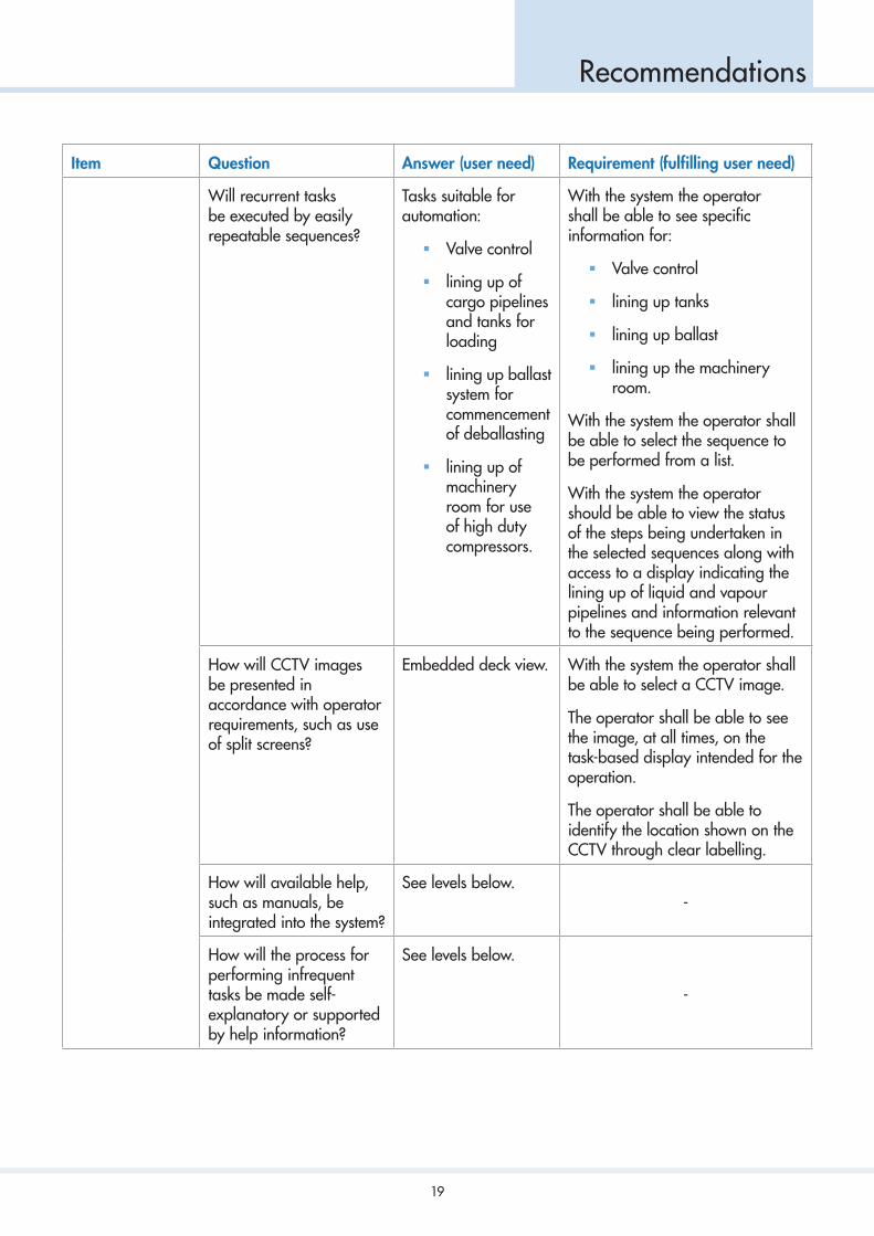
Recommendations
Item Question Answer (user need) Requirement (fulfilling user need)
Will recurrent tasks be executed by easily repeatable sequences?
Tasks suitable for automation:
� Valve control
� lining up ofcargo pipelinesand tanks forloading
� lining up ballastsystem forcommencementof deballasting
� lining up ofmachineryroom for useof high dutycompressors.
With the system the operator shall be able to see specific information for:
� Valve control
� lining up tanks
� lining up ballast
� lining up the machineryroom.
With the system the operator shall be able to select the sequence to be performed from a list.
With the system the operator should be able to view the status of the steps being undertaken in the selected sequences along with access to a display indicating the lining up of liquid and vapour pipelines and information relevant to the sequence being performed.
How will CCTV images be presented in accordance with operator requirements, such as use of split screens?
Embedded deck view. With the system the operator shall be able to select a CCTV image.
The operator shall be able to see the image, at all times, on the task-based display intended for the operation.
The operator shall be able to identify the location shown on the CCTV through clear labelling.
How will available help, such as manuals, be integrated into the system?
See levels below.-
How will the process for performing infrequent tasks be made self-explanatory or supported by help information?
See levels below.
-

20
Recommendations
Item Question Answer (user need) Requirement (fulfilling user need)
Control
Controls required to complete the task, ie completion.
How will the operator be presented with only the information relevant to the task?
For example, valve control requirements, valve pop up (face plate), type, position, order time delay and if it has a time out.
For controllable items, the operator should be able to access the controls within one click on the item to be controlled.
When pop ups (face plates) are used they shall only be open for a limited time (x16 second time out) and be movable on the display.
How will tasks that can be automated easily and safely be allocated to the system and the process be made transparent to the operator?
For example, tank level, overfill control, alarms and ESD.
With the system the operator shall be able to see:
� Tank level alarms
� tank overfill alarms,including set points
� status of overfill overridecontrols
� ESD system status
� ESD override control status.
Will recurrent tasks be executed by easily repeatable sequences?
Can be automatic sequence alongside manual operation.
With the system, when automated, the operator shall be able to select the set points.
With the system the operator shall be able to see the valve status.
With the system the operator shall be able to control the valve at any stage of the sequence.
How will CCTV images be presented in accordance with operator requirements, such as use of split screens?
N/A
-
How will available help, such as manuals, be integrated into the system?
More information and tag marks.
With the system the operator shall be able to view help in a menu within a specified number of clicks.
How will the process for performing infrequent tasks be made self-explanatory or supported by help information?
Flow control curves. Within the system the operator shall be able to view the flow control curves from the valve control menu.
16 A specified time, to be determined

21
Recommendations
Item Question Answer (user need) Requirement (fulfilling user need)
Valve position
Physical control of valves using the interface.
How will the operator be presented with only the information relevant to the task?
See lower level.
-
How will tasks that can be automated easily and safely be allocated to the system and the process be made transparent to the operator?
See lower level.
-
Will recurrent tasks be executed by easily repeatable sequences?
See lower level.-
How will CCTV images be presented in accordance with operator requirements, such as use of split screens?
See lower level.
-
How will available help, such as manuals, be integrated into the system?
See lower level.-
How will the process for performing infrequent tasks be made self-explanatory or supported by help information?
See lower level.
-
Table 2: Example application for valve position in the context of completion

22
Recommendations
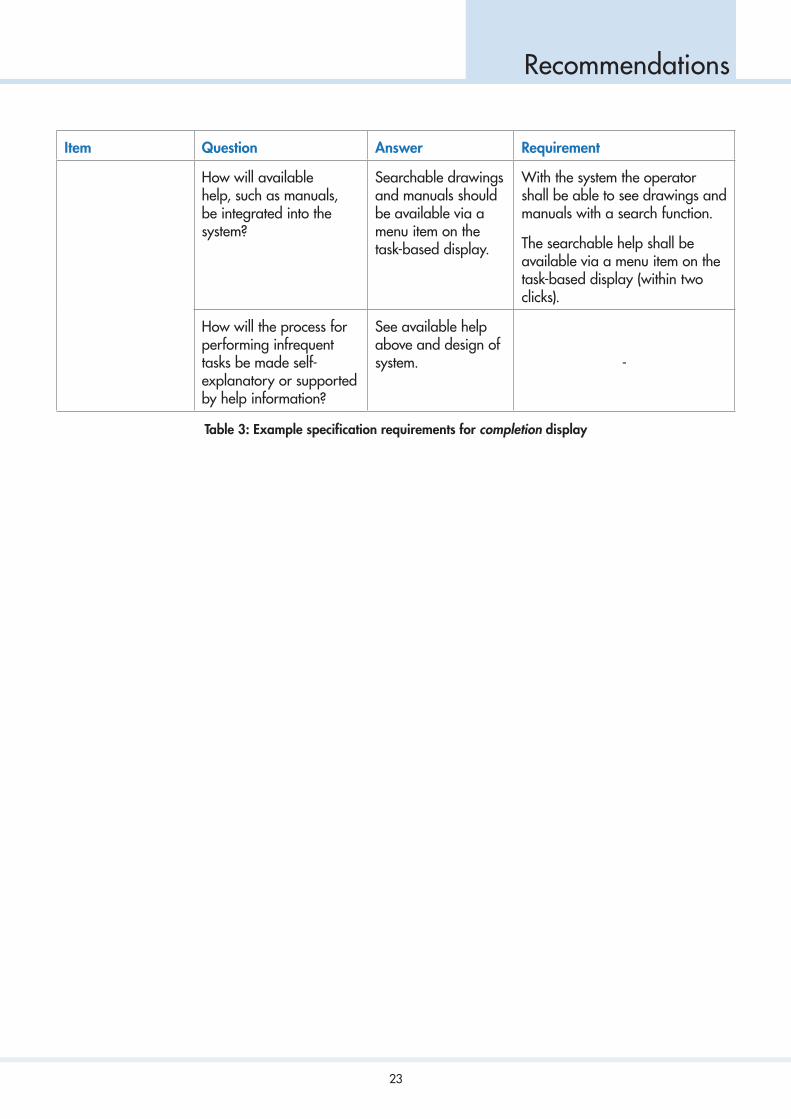
Table 3 shows what the output may look like at a higher task-based level for completion. At this stage, the requirement identification for the lower level tasks, such as levels and rates, pressure and valve position, will have been completed following the process demonstrated in the example in Table 2.
Item Question Answer Requirement
Completion How will the operator be presented with only the information relevant to the task?
See lower levels in the task analysis (see Table 2 example for valve position).
See relevant task analysis requirements from lower levels.
How will tasks that can be automated easily and safely be allocated to the system and the process be made transparent to the operator?
Completion sequences to be automated.
Display available to include sequence status, which step is running and next step (and when).
Access to sequence control available to the operator.
With the system the operator shall be able to select the appropriate automated completion sequence.
With the system the operator shall be able to see sequence status, which step is running, the next step and when it will run (at which limit).
With the system the operator shall be able to control the valve at any stage of the sequence.
Will recurrent tasks be executed by easily repeatable sequences?
Yes, automated sequences where beneficial to the operation but with ability to perform manually.
With the system the operator shall be able to perform the task manually or select automatic sequences.
Note: for manual operations see requirements for valve position.
How will CCTV images be presented in accordance with operator requirements, such as use of split screens?
A single CCTV image should be available at the workstation.
With the system the operator shall be able to select a CCTV image.
The operator shall be able to see the image at all times on the task-based display intended for the operation.
The operator shall be able to identify the location shown on the CCTV through clear labelling.
23
Recommendations
Item Question Answer Requirement
How will available help, such as manuals, be integrated into the system?
Searchable drawings and manuals should be available via a menu item on the task-based display.
With the system the operator shall be able to see drawings and manuals with a search function.
The searchable help shall be available via a menu item on the task-based display (within two clicks).
How will the process for performing infrequent tasks be made self-explanatory or supported by help information?
See available help above and design of system. -
Table 3: Example specification requirements for completion display

24
Recommendations
5.3 Step 3 – Development, Prototyping and Testing of Initial HMI Concepts
In this step, key elements of the interface are developed to the point that they can be tested in user trials. The proposed design would be expected to take account of the framework developed in Step 2, but more practical and effective solutions, should they emerge, should not be dismissed.
The task-based groupings from Step 2 may be further combined for similar tasks. These groupings will form the basis of the requirements that can be used to design a concept display, which can then be tested by users.
There are three possible approaches for designing the HMI:
1. Task-based: a combination of systems in single or multiple displays, that include the necessaryinformation and control functions for the normal execution of the task.
2. System-based: includes information about the system but is not tailored to the task.
3. A combination of task-based and system-based: where the overview display is task-based and sub-displays are system-based.
It is recommended that task-based displays are used, particularly for frequent operations.
For example, a grouping could be a combination of the loading and completion tasks, where similar information and controls will be used and the same display could be used, ie a loading display. The requirements derived from Step 2 for the loading and completion tasks would then be used by the designer to develop the concept display.
Feedback on the initial concept should be sought from users, which would then be used to refine it. Figure 3 shows an example initial concept design and user comments that might be anticipated from the first round of consultation.
Figure 4 shows the next iteration of the concept design, following initial user feedback. If this concept is considered to be sufficiently developed, it could be used by the system designer to develop a final concept. The final concept from the designer would then be tested again through user consultation before implementation.

25
Recommendations
Cou
rtesy
of K
ongs
berg
Mar
itim
e A
S
1A
utom
atio
n an
d Sa
fety
Man
ifold
trim
list
diag
ram
Setp
oint
s:
FPT
FPT
FPT
Barr
ier
1C
argo
Tan
k 1
Tim
eET
C: 2
335
Rate
: 289
0 m
3 /h
Vol:
8695
m3
Pres
s: 7
.2kP
A
Ave
tem
p: -1
62,5
C
FV 1
: 95%
FV 2
: 95%
12.3
689M
Car
go T
ank
1
Tim
eET
C: 2
335
Rate
: 289
0 m
3 /h
Vol:
8695
m3
Pres
s: 7
.2kP
A
Ave
tem
p: -1
62,5
C
FV 1
: 95%
FV 2
: 95%
12.3
689M
Car
go T
ank
1
Tim
eET
C: 2
335
Rate
: 289
0 m
3 /h
Vol:
8695
m3
Pres
s: 7
.2kP
A
Ave
tem
p: -1
62,5
C
FV 1
: 95%
FV 2
: 95%
12.3
689M
Car
go T
ank
1
Tim
eET
C: 2
335
Rate
: 289
0 m
3 /h
Vol:
8695
m3
Pres
s: 7
.2kP
A
Ave
tem
p: -1
62,5
C
FV 1
: 95%
FV 2
: 95%
12.3
689M
Barr
ier
1
Barr
ier
1
Barr
ier
1
FPT
FPT
FPT
FPT
FPT
FPT
Stab
ility
GM
:
BM:
Dra
fts:
FPT
FPT
FPT
Ring
Ope
nBW
TIn
activ
eSe
aO
pen
to L
ow
ETC
Bal
last:
HD
com
pres
sor
CC
TVAve
Tem
p: -1
62,5
C
Pres
s 3
.2 m
pa
CM
D C
TRL
09:0
2:59
09:0
2:40
TAG
1TA
G2
Ale
rt te
xt 1
Ale
rt te
xt 2
18:0
3:42
UTC
10
Show
flow
, pre
ssur
e an
d va
lve
posi
tion.
Shift
layo
ut fo
r ey
e tra
ckin
g –
mov
e al
l car
go in
form
atio
n to
left
and
balla
st to
rig
ht.
Rem
ove
barr
ier
info
rmat
ion.
Incl
ude
ESD
sta
tus.
Fo
r ba
llast
show
val
ve c
ontro
l, pr
essu
re, a
mpe
rage
and
flow
rat
e.
Figure 3: Example of a draft initial concept display for loading

26
Recommendations
Cou
rtesy
of K
ongs
berg
Mar
itim
e A
S
1Lo
adin
g
Man
ifold
Ave
. Tem
p:-1
62,5
ºC
3,2
mpa
3960
5 m
3/h
Pres
s. :
Clo
sed
ESD
sta
tus:
Aut
omat
ic lo
adin
gse
quen
ce:
Car
go ta
nk 1
Not
act
ive
Star
tSt
op
Vol:
FV1:
FV2:
Pres
s:
Ave
.Te
mp: Fill:
Car
go ta
nk 2
ETC
: 233
5
8695
m3
List:
BST1
PS
GM
:XX
X
Stab
ility
XXX
BM:
XXX
Dra
fts:
XXX
Ring
:
Out
let
Ope
nBW
T:In
activ
eSe
a:O
pen
to L
ow
-0.8
m 2350
m3
2.5
m
95
%
BST1
SS
2350
m3
2.5
m
95
%
BST2
PS
1200
m3
1.5
m
0
%
BST3
PS
6200
m3
10.5
m
95
%
BST4
PS
4200
m3
7.5
m
95
%
BST5
PS
5300
m3
6.0
m
95
%
BST2
SS
1200
m3
1.5
m
0
%
FPT
2350
m3
2.5
m
95
%
APT
5300
m3
6.0
m
95
%
BST3
SS
6200
m3
10.5
m
95
%
BST4
SS
4200
m3
7.5
m
95
%
BST5
SS
5300
m3
6.0
m
95
%
Trim
:0.
6 m
95 %
95 %
7.2
kPA
-162
,5 ºC
Rate
: 289
0 m
3/h
35 %
Vol:
FV1:
FV2:
Pres
s:
Ave
.Te
mp: Fill:
8695
m3
95 %
95 %
7.2
kPA
-162
,5 ºC
Rate
: 289
0 m
3/h
57 %
Vol:
FV1:
FV2:
Pres
s:
Ave
.Te
mp: Fill:
8695
m3
95 %
95 %
95 %
95 %
Pres
sure
Am
pera
ge
Flow
rat
e
2.5
bar
5000
m3/
h
Out
let
95 %
Pres
sure
Am
pera
ge
Flow
rat
e
2.5
bar
5000
m3/
h
Out
let
95 %
Pres
sure
Am
pera
ge
Flow
rat
e
2.5
bar
5000
m3/
h95
%
7.2
kPA
-162
,5 ºC
Rate
: 289
0 m
3/h
FV1:
FV2:
Rate
: 289
0 m
3/h
68 %
Vol:
Pres
s:
Ave
.Te
mp: Fill:
8695
m3
7.2
kPA
-162
,5 ºC
68 %
ETC
: 233
5
ETC
: 233
5
ETC
: 233
5
Car
go ta
nk 3
Car
go ta
nk 4
Sequ
ence
statu
s
Balla
st /
Deb
alla
st se
quen
ce s
tatu
sA
ctiv
e ste
p
Clo
sed
Clo
sed
Clo
sed
Clo
sed
Ope
n: 9
5%L1
P
L2P
VP
L3P
L4P
L1S
L2S
VS
L3S
L4S
Vapo
ur c
ross
over
val
ve
HD
com
pres
sor
Flow
3,2
kpa
70 IG
V
Pres
sure
Vane
pos
ition
CC
TV
Ope
n: 9
5%
Ope
n: 9
5%
Ope
n: 9
5%
Ope
n: 9
5%
Ope
n: 9
5%CM
D C
TRL
09:0
2:59
09:0
2:40
TAG
1A
lert
text
1A
lert
text
210
18:0
3:43
UTC
TAG
2
Figure 4: Example of the next iteration of a concept display for loading

27
Recommendations
At this stage of HMI development, the proposals are tested prior to finalising the project guidelines for interface design in Step 4.
As part of the concept display, control functions also need to be specified. For example, pop up control dialogues may be required for cargo and ballast valve control. For other items, a link through to a separate control window might be required.
5.4 Step 4 – Finalise Project Guidelines on Interface Design
During this step, lessons learnt during prototyping and testing in Step 3 are used. The final version of the project guidelines will form the basis for the detailed design of the control display interface. This will include, but not be limited to:
� Presentation of information
� control devices
� user guidance
� menu dialogues
� direct manipulation dialogues
� navigation
� alert management
� standards.
5.5 Step 5 – Detailed Design of Control and Display Interface
During this stage, the manufacturers and shipyard should develop the emerging interface. They should advise on any changes or compromises that could be necessary to successfully implement the requirements outlined in Steps 1 to 4. All decisions on the design, along with the reasoning behind them, should be documented together.
5.6 Step 6 – Verification and Validation
Verification and validation is an iterative process that should include manufacturers, shipyards, owners, operators and users.
This process should be conducted throughout the stages of control and display design, or at least from Step 3 onwards, and not just at the end of the process. This should ensure that all user requirements are implemented in the final design. For further information, see ISO 11064-7 17.
17 ISO 11064 – Ergonomic design of control centres – Part 7: Principles for the evaluation of control centres (Reference 2)

28
Recommendations
6. Further Guidance
This section provides further guidance for screen-based liquefied gas carrier CCR design.
6.1 General
All information presented on a visual display should have a useful purpose for the operator and unnecessary items should be avoided.
The more displays included in the system, the more difficult it becomes to navigate for the operator. If displays are unnecessary, they should be avoided.
The focus should be on what is active and why, not inactive possibilities like ESDs and interlocks. This should facilitate operator action on active elements.
6.2 Alarm Management
The effective presentation of alarms is a vitally important issue in CCR design. For further information, see Recommendations for Management of Cargo Alarm Systems18.
6.3 Types and Number of Pages (Navigating the System)
In most cases, it is not possible to present all the necessary data to undertake a task on a single display. It will be necessary to subdivide this information, with task overview on one display and further information on sub-displays, depending on their importance and frequency of use for the task.
A key requirement is that the data should be easy to find whenever needed.
Information pages should be capable of simultaneously presenting the set of data necessary for handling the worst-case scenario. This could include information, static graphics and controls. Toggling between different windows when performing a particular task should be avoided.
Where operating practices demand, dedicated overview information should be provided for the display parameters such as safety-related alarms. For further information see Section 16, ‘Critical Alarm and Action Panel (CAAP)’ in Recommendations for Management of Cargo Alarm Systems.
6.4 Windowing
The real-time environment found in control rooms imposes special requirements when using multiple windows on a display.
When considering the number of windows capable of being displayed at the same time, the visibility of information should be of primary importance. Relevant information should not be obscured by multiple windows, which may result in limits on the number being considered.
No window should obscure or overlay safety critical information or alarms.
6.5 Redistribution of Pages to Display Devices
The operator should be able to view pages on different displays to compensate for a failed display monitor. Each screen should be capable of displaying all categories of information.
18 SIGTTO – Recommendations for Management of Cargo Alarm Systems (Reference 5)

29
Recommendations
6.6 Developing Formats
A format is a particular way of presenting data to convey information to the user. It is important that the most appropriate format is chosen to enable the user to correctly interpret system outputs.
Formats include text, forms, histograms, bar charts, tables, mimics and diagrams, and can occupy an entire page or part of one. Reference should be made to industry or International Maritime Organization (IMO) recommendations, where applicable.
As a minimum, there should be consistency in orientation, direction of flow and formatting across all diagrams and mimics.
6.7 Trend Curves
When drawing trend curves, it is recommended that the following ergonomic guidance from ISO 1106419 is followed:
� Trend lines should be about twice as thick as the thickest line used in the background grids and scalebase lines
� if multiple parameters are being displayed on a trend, colours should be used and a wide spectralseparation between the colours should be provided
� trend displays should be capable of showing data collected during time intervals of different lengths
� trend rates should not fluctuate as a result of minor changes in data or oscillatory behaviour that can besuperimposed on a well-defined trend
� curves representing planned, projected or extrapolated data should be distinctive from curvesrepresenting actual data
� where applicable, upper and lower alarm limits should be indicated.
6.8 Graphs
Graphs are representations showing relationships between variables, such as temperature and pressure, differential barrier pressure and upper and lower tank temperature.
When creating graphs, it is recommended that the following guidance from ISO 11064 is taken into account:
� Graphs should be self-descriptive. It should be possible to interpret the data without consulting additionalinformation
� it should be possible to identify multiple curves without a separate legend
� if multiple parameters are being displayed on a graph, colours should be used and a wide spectralseparation between the colours should be provided
� it can be helpful for the target area, ie the preferred combination of X and Y axis values, to begraphically defined
� graphs that form recognisable patterns, relating to normal or abnormal conditions, can be helpful to theuser, ie spider graphs.
19 ISO 11064 – Ergonomic design of control centres (Reference 2)

30
Recommendations
6.9 Flowcharts
A flowchart is a diagram that illustrates sequential relationships among elements or events. ISO 11064 recommends the following for designing flowchart presentations for defined tasks:
� The available decision options should be presented in a logical order
� only a single decision should be required at each step
� the information should be presented in a logical, clear manner, through top-to-bottom or left-to-rightsequences.
6.10 Mimics and Diagrams
A mimic is a format combining graphics and alphanumerics, used to integrate system components into functionally orientated diagrams that reflect component relationships.
ISO 11064 recommends the following for creating mimics or diagrams:
� The mimic or diagram should contain the minimum amount of detail necessary to produce a meaningfulsituational model for the operator’s task
� the user should be able to easily identify any system components presented on a display (mimic diagram)and how they interact
� the use of flowpath lines should be minimised, but when used origin and destination points should beclearly labelled or begin and end at labelled components. Flow direction should be clearly indicated.
Different presentation may be required for different uses, and should be prioritised with task-based mimics for operations. For example, this could consider whether the display of all the pipelines is necessary or whether something more useful (dynamic) should be displayed instead. Piping and instrumentation diagrams (P&ID) may be useful for maintenance or delivery, but are not suitable as operational mimics.
6.11 Tags
There should be a documented defined logic to the system of naming and numbering tags. This information should be readily available to the operator.
6.12 Selecting Control Devices
Control devices should be seen as inputs to the system design and the graphical user interface. The type of device selected will influence the type of interface, in terms of the size and interaction principles with the elements on the display.
When selecting control devices, refer to Recommendations for Designing Cargo Control Rooms20.
6.13 Overview Displays
Control workstations should have overview information available and show the state of all facilities the operator is responsible for. This should be a starting point for navigating the hierarchy of more detailed pages. These overview displays can be on the workstation, closely coupled to specific workstations or remote and shared by a number of operators.
Frequently monitored events and trend displays may be employed as a type of overview display. An alternative recommendation is single-key access for frequently referenced data.
20 SIGTTO – Recommendations for Designing Cargo Control Rooms (Reference 1)

31
Recommendations
Where an overview system display (OSD) is used, important functions typically include provision of facility status overviews, directions to operators on additional information on operator stations and supporting crew coordination, communication and collaboration.
In practice, a combination of an off workstation, shared overview display and desk-based monitors can be appropriate where requirements for team working, visitors, mobility of users and provision of secondary support information are to be accommodated.
Important aspects to consider in OSD system design are:
� Allocation of information between on workstation displays and the shared off workstation display
� information structuring on the OSD
� user-system interaction with the OSD system
� consistency and compatibility between the OSD system and the rest of the operator stations.


Annexes

35
Annexes
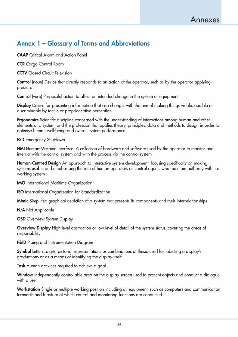
Annex 1 – Glossary of Terms and Abbreviations
CAAP Critical Alarm and Action Panel
CCR Cargo Control Room
CCTV Closed Circuit Television
Control (noun) Device that directly responds to an action of the operator, such as by the operator applying pressure
Control (verb) Purposeful action to affect an intended change in the system or equipment
Display Device for presenting information that can change, with the aim of making things visible, audible or discriminable by tactile or proprioceptive perception
Ergonomics Scientific discipline concerned with the understanding of interactions among human and other elements of a system, and the profession that applies theory, principles, data and methods to design in order to optimise human well-being and overall system performance
ESD Emergency Shutdown
HMI Human-Machine Interface. A collection of hardware and software used by the operator to monitor and interact with the control system and with the process via the control system
Human-Centred Design An approach to interactive system development, focusing specifically on making systems usable and emphasising the role of human operators as control agents who maintain authority within a working system
IMO International Maritime Organization
ISO International Organization for Standardization
Mimic Simplified graphical depiction of a system that presents its components and their interrelationships
N/A Not Applicable
OSD Overview System Display
Overview Display High-level abstraction or low level of detail of the system status, covering the areas of responsibility
P&ID Piping and Instrumentation Diagram
Symbol Letters, digits, pictorial representations or combinations of these, used for labelling a display’s graduations or as a means of identifying the display itself
Task Human activities required to achieve a goal
Window Independently controllable area on the display screen used to present objects and conduct a dialogue with a user
Workstation Single or multiple working position including all equipment, such as computers and communication terminals and furniture at which control and monitoring functions are conducted

36
Annexes
Annex 2 – Reference List
1. SIGTTO – Recommendations for Designing Cargo Control Rooms
2. ISO 11064 – Ergonomic design of control centres
3. ISO 9241 – Ergonomics of human-system interaction
4. ISO 26800 – Ergonomics — General approach, principles and concepts
5. SIGTTO – Recommendations for Management of Cargo Alarm Systems
6. ISO 25065 – Systems and software engineering — Software product Quality Requirements andEvaluation (SQuaRE) — Common Industry Format (CIF) for Usability: User requirements specification
