recommendation itu-r bt.2027 - serial …!msw-e.docx · web viewitu-r policy on ipr is described in...
TRANSCRIPT

Recommendation ITU-R BT.2027(08/2012)
Serial digital interface for production and international exchangeof HDTV 3DTV programmes
BT SeriesBroadcasting service
(television)

ii Rec. ITU-R BT.2027
Foreword
The role of the Radiocommunication Sector is to ensure the rational, equitable, efficient and economical use of the radio-frequency spectrum by all radiocommunication services, including satellite services, and carry out studies without limit of frequency range on the basis of which Recommendations are adopted.
The regulatory and policy functions of the Radiocommunication Sector are performed by World and Regional Radiocommunication Conferences and Radiocommunication Assemblies supported by Study Groups.
Policy on Intellectual Property Right (IPR)
ITU-R policy on IPR is described in the Common Patent Policy for ITU-T/ITU-R/ISO/IEC referenced in Annex 1 of Resolution ITU-R 1. Forms to be used for the submission of patent statements and licensing declarations by patent holders are available from http://www.itu.int/ITU-R/go/patents/en where the Guidelines for Implementation of the Common Patent Policy for ITU-T/ITU-R/ISO/IEC and the ITU-R patent information database can also be found.
Series of ITU-R Recommendations(Also available online at http://www.itu.int/publ/R-REC/en)
Series Title
BO Satellite deliveryBR Recording for production, archival and play-out; film for televisionBS Broadcasting service (sound)BT Broadcasting service (television)F Fixed serviceM Mobile, radiodetermination, amateur and related satellite servicesP Radiowave propagationRA Radio astronomyRS Remote sensing systemsS Fixed-satellite serviceSA Space applications and meteorologySF Frequency sharing and coordination between fixed-satellite and fixed service systemsSM Spectrum managementSNG Satellite news gatheringTF Time signals and frequency standards emissionsV Vocabulary and related subjects
Note: This ITU-R Recommendation was approved in English under the procedure detailed in Resolution ITU-R 1.
Electronic PublicationGeneva, 2012
ITU 2012
All rights reserved. No part of this publication may be reproduced, by any means whatsoever, without written permission of ITU.

Rec. ITU-R BT.2027 1
RECOMMENDATION ITU-R BT.2027
Serial digital interface for production and international exchangeof HDTV 3DTV1 programmes
(2012)
Scope
This Recommendation specifies the serial digital interface for production and international exchange of HDTV 3DTV programmes.
The ITU Radiocommunication Assembly,
considering
a) that 3DTV programmes are already being produced in several countries;
b) that the high-definition common image format of 1920 × 1080 pixels at 60, 50, 30, 25 and 24 frames a second has already been agreed as the international exchange format for HDTV programmes;
c) that the parameters of the two HDTV 3DTV signals (Le and Re)2 exactly match the parameters for HDTV specified in Recommendation ITU-R BT.709;
d) that the parameters specified in Recommendation ITU-R BT.709 meet the quality goals set for HDTV 3DTV;
e) that programmes produced and archived using the parameters specified in Recommendation ITU-R BT.709 will have long-term reusability;
f) that the relative timing between the Le and Re data streams at the point of exchange needs to be sufficiently accurate to allow downstream devices to resynchronize the frames for display,
recommends
1 that the serial digital interface parameters defined in Annex 1 should be used for production and international exchange of HDTV 3DTV programmes;
2 that Note 1 be considered part of the Recommendation.
NOTE 1 – Compliance with this Recommendation is voluntary. However, the Recommendation may contain certain mandatory provisions (e.g. to ensure interoperability or applicability) and compliance with the Recommendation is achieved when all of these mandatory provisions are met. The words “shall” or some other obligatory language such as “must” and the negative equivalents are used to express requirements.
1 In the context of this Recommendation, the term 3DTV is used to convey a stereoscopic image or image pair.
2 Le and Re are abbreviations for Left eye and Right eye, respectively.

2 Rec. ITU-R BT.2027
Annex 1
This Recommendation covers interfaces for the 4:2:2 sampling lattice at the frame rates of 24, 24/1.001, 25, 30 and 30/1.001 with 8 and 10-bit depth.
These interfaces for 3DTV images shall carry the Le and the Re images as two full resolution images along with audio and other data.
The Le image and the Re image shall have the same image format structure.
The electrical or optical characteristics of each link of the interface shall be in conformance with Recommendations ITU-R BT.1120 and BT.1367.
1 Dual 1.5 Gbit/s interface
One link of this interface shall carry an Le image and the other link shall carry an Re image, and shall be identified by the payload identifier.
Each Le and Re image of the stereoscopic image pair shall be of the same format and structure and shall be constructed as an individual 10-bit interface in accordance with Recommendation ITU-R BT.1120.NOTE – Each link can be treated as a 2D stream and can be processed with existing 2D equipment.
The timing difference between the serial digital clocks and EAV / SAV of the Le link and the Re link shall not exceed 400 ns at the source. This difference should be taken into consideration when designing systems and destination equipment input stages.
The 10-bit interfaces so constructed shall contain timing reference code words (SAV/EAV), line numbers and line-based CRCs as defined in Recommendation ITU-R BT.1120.
Each parallel 10-bit interface shall be frame-, line- and word-aligned, having an interface clock frequency of 148.5 MHz or 148.5/1.001 MHz as shown in Fig. 1.
FIGURE 1Dual 1.5 Gbit/s interface for 3DTV
1.1 Audio and ancillary data mapping
When present, ancillary data shall be mapped into the ancillary data space of the Le link and the Re link and shall be in conformance with Recommendation ITU-R BT.1364. The ancillary data shall be mapped onto the Le link first and any remaining data shall be mapped into the ancillary data space of the Re link. In some applications, there may be ancillary data intended for the Re or Le link only, in which case that ancillary data shall be inserted into the appropriate link.

Rec. ITU-R BT.2027 3
When present, audio data shall be mapped into the ancillary data space of the Le link and the Re link in conformance with Recommendation ITU-R BT.1365. The audio data shall be mapped onto the Le link first and any remaining data shall then be mapped onto the Re link. In some applications, audio data of the Le link may be duplicated in the Re link.
Time code should be present and shall be mapped into the ancillary data space of the Le link and Re link in conformance with Recommendation ITU-R BT.1366. Time address values shall be identical and may be used to establish synchronization of the Le and Re signals.
1.2 Payload identification
The payload identifier data structure shall be in conformance with Recommendation ITU-R BT.1614 and shall be mapped onto each link of the interface to identify the Le/Re images, picture frame rate, sampling structure, etc. Payload ID packets should be on the lines indicated below, and shall be inserted into the Y-channel of the data stream of each link.
1125 line interlaced systems placement
For digital interfaces having 1125 lines with interlaced (I) and progressive segmented frame (PsF) scanning structures, the payload ID ancillary data packet shall be added once per field. The location of the payload ID ancillary data packet should be on the following line. – 1125/I (field 1): Line 10– 1125/I (field 2): Line 572
1125 line progressive systems placement
For digital interfaces having 1125 lines with a progressive (P) scanning structure, the payload ancillary data packet shall be added once per frame. The location of the ancillary data packet should be on the following line:– 1125/P: Line 10
TABLE 1
Payload identifier overview
Bits Byte 1 Byte 2 Byte 3 Byte 4
Bit 7 1 Interlaced (0h) or progressive (1h) transport Horizontal pixel
count1920 (0h) all other
values reserved
Reserved (0h)
Bit 6 0 Interlaced (0h) or progressive (1h) picture
Stream assignmentLe stream (0h) or Re stream
(1h)
Bit 5 1 ReservedAspect ratio 16:9 (1h)
Unknown (0h)Reserved (0h)
Bit 4 1 Reserved Reserved Reserved (0h)

4 Rec. ITU-R BT.2027
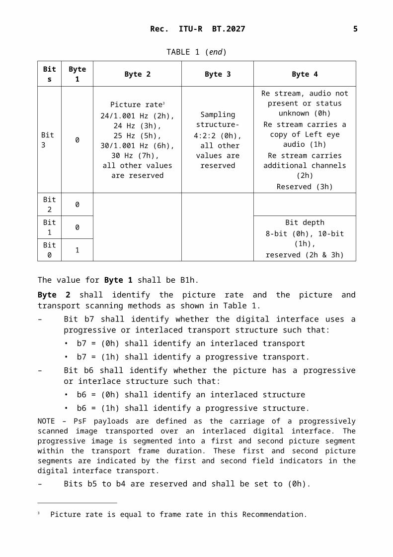
TABLE 1 (end)
Bits Byte 1 Byte 2 Byte 3 Byte 4
Bit 3 0
Picture rate3
24/1.001 Hz (2h),24 Hz (3h),25 Hz (5h),
30/1.001 Hz (6h),30 Hz (7h),
all other values are reserved
Sampling structure-4:2:2 (0h),
all other values are reserved
Re stream, audio not present or status unknown (0h)
Re stream carries a copy of Left eye audio (1h)
Re stream carries additional channels (2h)Reserved (3h)
Bit 2 0Bit 1 0 Bit depth
8-bit (0h), 10-bit (1h),reserved (2h & 3h)Bit 0 1
The value for Byte 1 shall be B1h.
Byte 2 shall identify the picture rate and the picture and transport scanning methods as shown in Table 1.– Bit b7 shall identify whether the digital interface uses a progressive or interlaced transport
structure such that:• b7 = (0h) shall identify an interlaced transport• b7 = (1h) shall identify a progressive transport.
– Bit b6 shall identify whether the picture has a progressive or interlace structure such that:• b6 = (0h) shall identify an interlaced structure• b6 = (1h) shall identify a progressive structure.
NOTE – PsF payloads are defined as the carriage of a progressively scanned image transported over an interlaced digital interface. The progressive image is segmented into a first and second picture segment within the transport frame duration. These first and second picture segments are indicated by the first and second field indicators in the digital interface transport.– Bits b5 to b4 are reserved and shall be set to (0h).– Bits b3 to b0 shall identify the picture rate in Hz.
Byte 3 shall identify the aspect ratio and sampling structure as shown in Table 1.– Bits b6 and b7 shall identify the horizontal pixel count:
• (0h) shall identify 1920 pixels• (1h) Reserved• (2h) Reserved• (3h) Reserved.
– Bit b5 shall identify the image aspect ratio:• b5 = (0h) shall identify an image with unknown aspect ratio• b5 = (1h) shall identify an image with a 16:9 aspect ratio.
3 Picture rate is equal to frame rate in this Recommendation.

Rec. ITU-R BT.2027 5
– Bit b4 is reserved and shall be set to (0h).
Bits b3 to b0 shall identify the sampling structure and be set to value (0h), which corresponds to 4:2:2 (Y′ C′B C′R).
Byte 4 shall identify other aspects of the payload as shown in Table 1.– Bit b7 is reserved and shall be set to (0h).– Bit b6 shall identify whether the stream carries the Le or Re images:
• b6 = (0h) shall Identify an Le image• b6 = (1h) shall identify an Re image.
– Bits b4 and b5 shall be reserved and set to (0h).– For the Le stream, bits b2 and b3 shall be reserved and set to (0h).– For the Re stream, bits b2 and b3 shall signal the nature of any audio data carried in the Re
stream:• (0h) shall identify that no audio is present in the Re stream or that the status of any
audio signals is unknown• (1h) shall identify that the Re stream carries a copy of the Le stream audio• (2h) shall identify that Re stream carries additional audio channels 17-32. When the
audio sampling is 96 kHz, these additional channels shall be channels 9-16• (3h) is reserved.
– Bits b1 and b0 shall identify the image pixel bit depth:• (0h) shall identify quantization using 8 bits per sample• (1h) shall identify quantization using 10 bits per sample• (2h) and (3h) are reserved.
2 Single 3 Gbit/s interface
The image formats to be transported by a single link 3 Gbit/s interface are the same as the image formats that can be transported by a dual 1.5 Gbit/s interface as outlined in § 1.
Each Le and Re image of the stereo image pair shall be constructed as an individual 10-bit interface in accordance with § 1.
The 10-bit interfaces so constructed shall contain timing reference code words (SAV/EAV), line numbers and line-based CRCs as defined in Recommendation ITU-R BT.1120.
Each parallel 10-bit interface shall be frame-, line- and word-aligned, having an interface frequency of 148.5 MHz or 148.5/1.001 MHz as shown in Fig. 1.
The Le and Re 10-bit interfaces so constructed shall be mapped into the 20-bit virtual interface defined in Recommendation ITU-R BT.1120 in § 4.6 – Single link 3 Gbit/s mapping – Dual link source.
The Le interface stream shall be mapped into data stream 1 of the virtual interface and the Re interface stream shall be mapped into data stream 2 of the virtual interface as shown in the diagram of Fig. 2. Any timing difference between the Le and Re interface streams shall be corrected prior to mapping into the virtual interface.

6 Rec. ITU-R BT.2027
2.1 Audio and other ancillary data mapping
When present, ancillary data packets including audio data and time code shall be mapped into the Le and Re 10-bit interfaces as defined in § 1.
2.2 Payload identification
The payload identifier shall be mapped onto each Le and Re 10-bit interface as defined in § 1. Bytes 2, 3 and 4 of the payload identifier shall be in conformance with the picture rate, sampling structure, aspect ratio, and bit depth, etc. as defined in § 1.
Byte 1 of the payload identifier shall be 8Fh.
Other parameters contained within the payload identifier are the same as in § 1.
Rec. ITU-R BT.2027 7
FIGURE 2Dual stream mapping for single 3 Gbit/s interface