reciprocating compressor - design and selection · pdf filereciprocating compressor i. purpose...
TRANSCRIPT

RECIPROCATING COMPRESSOR
TABLE OF CONTENT
I. Purpose 2 II. Units and Symbols 2 III. Unit Conversion 3 IV. Main Component of Reciprocating Compressor 3 V. Operating Range of Reciprocating Compressor 4 VI. Gas Compression 5 VII. Intercooler and Aftercooler 6 VIII. Compressor Control 7 IX. Calculation Formula 9 Appendix A. Size, Efficiency and Losses 11 Appendix B. Gas Properties 14 Appendix C. Compressor Control 19
Page : 1

RECIPROCATING COMPRESSOR
I. PURPOSE
To be used for selection, application into the system, power and cooling water estimation. This manual does not for designing reciprocating compressor and the related parts.
II. SYMBOLS AND UNIT
Designation Symbol Unit Pressure p bar A Pressure ratio r - Temperature t C Absolute Temperature T K Capacity (volume flow) Q m3 / hr Piston displacement volume VP m3 Volumetric efficiency ηV - Mechanical Efficiency ηM - Power P kW Brake horse power BHP kW Gas horse power GHP kW Speed N RPM Head H m Gas Constant R kJ/kg.K Molecular Mass MW kg/kgmole (=lb/lbmole )
Mole MM kgmole ( kgmole/h or kmol/h ) Density DS kg/m3 Specific Gravity SG Specific volume v m3/kg Specific Heat Cp kJ/kg.K Mass Flowrate G kg / hr Adiabatic Exponent k - Polytropic Exponent n - Isentropic exponent m - Compressibility Factor Z (capital) - Gravity g m/s2 (9.81) Heat Capacity MCp kJ/kgmole Enthalpy h kJ/kg Enthalpy different Δh kJ/kg Entropy s kJ/kg.K Piston diameter D mm Piston speed U m/s No. of stage i Integer number No. of throw z Integer number Power loss PLOSS kW Subkrip (Subscript) cr atau CR Critical a Adiabatic process red atau R Reduced p Polytropic s atau S Suction 1, 2 etc. Position d atau D Discharge I, II etc. Stage No. G Gas/GHP N Normal condition ( 0 O C , 1.013 bar A ) V Volumetric MAX, max Maximum STG Stage, throw
Page : 2
RECIPROCATING COMPRESSOR
III. UNIT CONVERSION
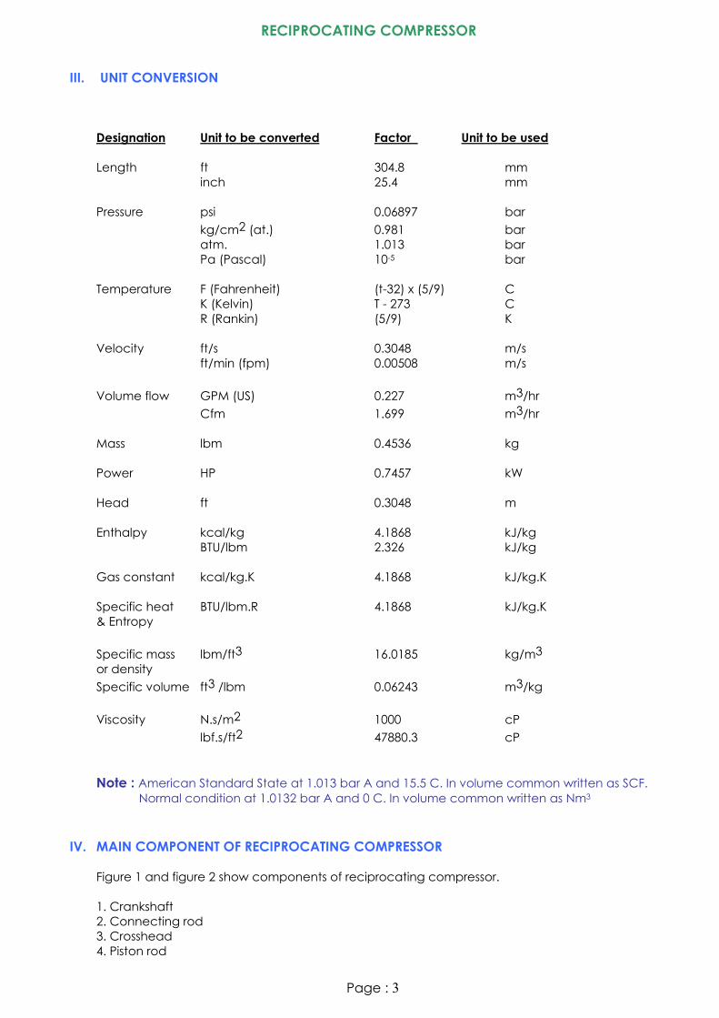
Designation Unit to be converted Factor Unit to be used Length ft 304.8 mm inch 25.4 mm Pressure psi 0.06897 bar kg/cm2 (at.) 0.981 bar atm. 1.013 bar Pa (Pascal) 10-5 bar
Temperature F (Fahrenheit) (t-32) x (5/9) C K (Kelvin) T - 273 C R (Rankin) (5/9) K Velocity ft/s 0.3048 m/s ft/min (fpm) 0.00508 m/s Volume flow GPM (US) 0.227 m3/hr Cfm 1.699 m3/hr Mass lbm 0.4536 kg Power HP 0.7457 kW Head ft 0.3048 m Enthalpy kcal/kg 4.1868 kJ/kg BTU/lbm 2.326 kJ/kg Gas constant kcal/kg.K 4.1868 kJ/kg.K Specific heat BTU/lbm.R 4.1868 kJ/kg.K & Entropy Specific mass lbm/ft3 16.0185 kg/m3 or density Specific volume ft3 /lbm 0.06243 m3/kg Viscosity N.s/m2 1000 cP lbf.s/ft2 47880.3 cP
Note : American Standard State at 1.013 bar A and 15.5 C. In volume common written as SCF. Normal condition at 1.0132 bar A and 0 C. In volume common written as Nm3
IV. MAIN COMPONENT OF RECIPROCATING COMPRESSOR
Figure 1 and figure 2 show components of reciprocating compressor. 1. Crankshaft 2. Connecting rod 3. Crosshead 4. Piston rod
Page : 3

RECIPROCATING COMPRESSOR
5. Piston and their rings 6. Packing rings or seal rings 7. Check valves 8. Suction unloader and clearance pocket 9. Distance pieces
Figure 1. Cross Section of Typical Reciprocating Compressor
Figure 2. Cross Section of Typical Reciprocating Compressor V. OPERATING RANGE OF RECIPROCATING COMPRESSOR
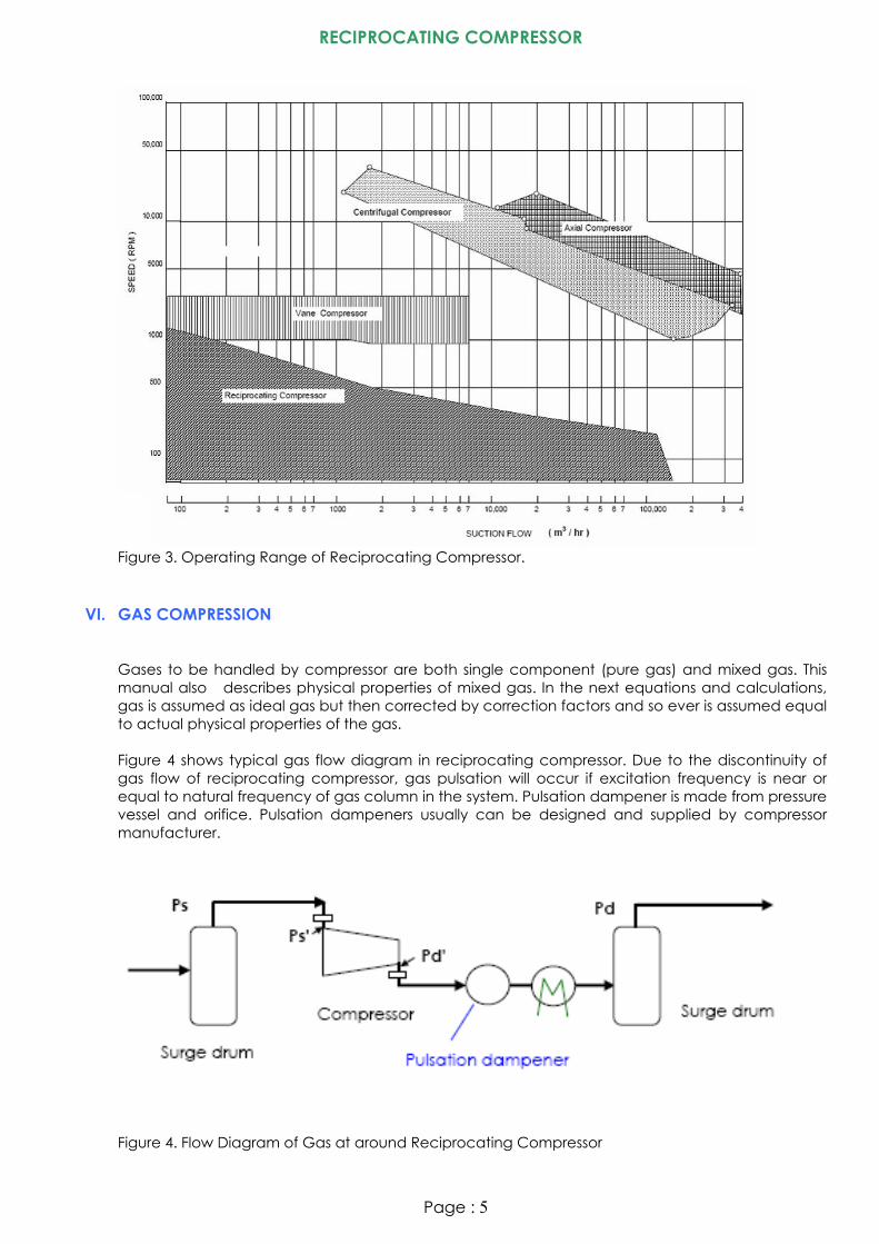
Figure 3 shows operating range of reciprocating compressor base on suction volume flow against speed (RPM). Comparing to the other compressor types, reciprocating compressor has lowest operating speed where below 1000 RPM. Compression ratio of reciprocating compressor is up to more than 500 where is highest compression ratio compared to the other compressor types.
Page : 4
RECIPROCATING COMPRESSOR
Figure 3. Operating Range of Reciprocating Compressor.
VI. GAS COMPRESSION
Gases to be handled by compressor are both single component (pure gas) and mixed gas. This manual also describes physical properties of mixed gas. In the next equations and calculations, gas is assumed as ideal gas but then corrected by correction factors and so ever is assumed equal to actual physical properties of the gas. Figure 4 shows typical gas flow diagram in reciprocating compressor. Due to the discontinuity of gas flow of reciprocating compressor, gas pulsation will occur if excitation frequency is near or equal to natural frequency of gas column in the system. Pulsation dampener is made from pressure vessel and orifice. Pulsation dampeners usually can be designed and supplied by compressor manufacturer.
Figure 4. Flow Diagram of Gas at around Reciprocating Compressor
Page : 5

RECIPROCATING COMPRESSOR
There is pressure drop at suction side and discharge side of reciprocating compressor due to inlet / outlet and check valve constructions. Ps is system suction pressure, Ps’ is intake pressure of compressor cylinder, Pd’ is outlet pressure of compressor cylinder and Pd is discharge pressure to the system. Gas compression process in reciprocating compressor can be expressed such in figure 5. In the way back from point 1 to point 3, gas flows or gas induced to cylinder is only from point 2 to 3, because from point 1 to 2 there is only gas expansion of residual gas in clearance space. Ratio of effective stroke (Le) by physical stroke (Lp) named volumetric efficiency.
Figure 5. Idealized Gas compression Process in Piston Displacement and Pressure VII. INTERCOOLER AND AFTERCOOLER
Intercooler is required when compressed gas temperature to the next compression will higher than permitted temperature during or after compression. Permitted gas temperature during compression is depending to the weakest of constructed components, cooling media or gas compressed properties itself. The following are typical permitted temperature in reciprocating compressor.
Page : 6

RECIPROCATING COMPRESSOR
Designation Permitted temperature ( C) Oil lubricated air compressor 160 for multi stage
200 for single stage Pure oxygen and pure chlorine 120 Dry cylinder with Teflon seals 200
Other typical standard give maximum temperature 150 C for any gas based on adiabatic process calculation. If intercooler is cooling water media type, differential temperature between inlet cooling water and exhaust gas from intercooler shall be not so close, i.e. higher than 5 oC or 8 to 10 oC is most used. Aftercooler is required when discharge system temperature of compressor is limited or to be cooled due to process requirements.
VIII. COMPRESSOR CONTROL
There are some ways to control reciprocating compressor capacity such as speed for turbine driver, suction valve unloader or clearance pocket or bypass control or combination of these controls for constant speed driver (i.e. electric motor). See also Appendix C. Figure 6 shows gas process in clearance pocket control. When residual gas space is larger, intake volume will decrease. Figure 7 shows gas process in suction valve unloader. Suction valve unloader controls pressure drop between suction pressure and cylinder suction pressure ( ΔPs’) and by itself, volume flow is also controlled because given energy by driver is constant or equal. Figure 8 shows gas process in bypass control system. Effective volume will reduced when bypass volume is become parts of total volume.
Figure 6. Volume Control by Clearance Pocket
Page : 7

RECIPROCATING COMPRESSOR
Figure 7. Volume Control by Suction Valve Unloader
Figure 8. Gas Process in Bypass Controller.
Page : 8

RECIPROCATING COMPRESSOR
IX. CALCULATION FORMULA All following calculation formula are related to required power, required cooling water, number of stage and gas condition for each stage of gas in reciprocating compressor. Brake horse power, BHP = MGHP η/ (kW) (1) where ηM is mechanical efficiency, see Appendix A. Gas horse power
GHP = )(6.3
10... 6
V
gHGη
−
(kW) (2)
where G is induced mass flow and ηV is volumetric efficiency, see Appendix A. G = DSS . Qs (kg/h) (3) DSS is density of gas in kg/m3 and Qs is induced volume flow in m3/hr For perfect gas,
Qs = )(69.269
.ps
QnTs and Qd =
)(69.269.pd
QnTd (m3/hr) (4)
Where Qn is volume flow at normal condition ( 0 C and 1.013 bar A)
DSS = TsRsps
.)(100
, DSN = )(273
3.101R
and DSD = psTdpdTsDSs
...
(m3 /hr) (5)
For actual gas with compressibility correction,
Qs = )(69.269
..psZsQnTs
and Qd = )(69.269
..pdZdQnTd
(m3/hr) where ZN ≈ 1 (6)
DSS = ZsTsRsps..
)(100 , and DSD =
ZdTdZspdTsDSs
....
(m3 /hr) (7)
Hydrodynamic head in adiabatic process,
H = }1)''}{(
1{))()((1000 )1(
−−
−kk
pspd
kk
gTsRZs
(m) (8)
With substitution, GHP can be rewritten as the following equation,
GHP = ⎪⎭
⎪⎬
⎫
⎪⎩
⎪⎨
⎧−⎟⎟
⎠
⎞⎜⎜⎝
⎛
⎭⎬⎫
⎩⎨⎧
−
⎟⎠⎞
⎜⎝⎛ −
1''
1)/('02778.0
1kk
VV pspd
kkQsxpsx
ηλη (9)
Where (pd’/ps’ = r’ ) is compression ratio. pd’ and ps’ are in absolute pressure (bar A) and
Page : 9

RECIPROCATING COMPRESSOR
k is adiabatic exponent. Following figure 9 shows relation between compression process and the exponents. Isothermal compression is where gas always in constant temperature during compression. Adiabatic compression is where gas always in constant entropy during compression. There is no heat loss or heat addition and no friction that potentially produce heat. Polytropic compression is where during gas compression there is heat loss and friction as an actual compression process. GHP in equation (1) can be written Figure 9. Gas Compression Process and Their Exponents Practically, n is almost equal with k for reciprocating compressor without special cooling process. R = Ro / MW (kJ/kg.K) Ro = 8.314 (kJ/kgmole.K) See Appendix B for R, MW, k and Z for several gas. Discharge Temperature
Td = Ts .)1(
)''( k
k
pspd −
(10)
If discharge temperature is limited at Tdmax, then maximum pressure ratio become
MAXpspd )
''( =
)1
()max( −k
k
TsTd
(11)
Average piston speed (also piston rod and crosshead),
U = 60
002.0 NxLx m/s (12)
Where L is piston stroke in mm, N crankshaft speed in RPM. Several data shows U is in the range of 2 up to 6 m/s.
Page : 10

RECIPROCATING COMPRESSOR
APPENDIX A. SIZE, EFFICIENCY, LOSSES AND MAXIMUM FRAME BHP A.1. VOLUMETRIC EFFICIENCY
Piston displacement volume, VP = 7.8675 x 10⁻¹⁰ x D2 (m3) (A.1) Piston displacement volume flow / acting, QP = 4.7205 x 10⁻⁸ x D2 x N (m3/hr) (A.2) Adiabatic volumetric efficiency,
ηVO = )01.0(1'11
cxr k ⎟⎟⎠
⎞⎜⎜⎝
⎛−− and c <
)1'(
)1(1001
0
−
− −
k
EXPv
r
η , ηVO-EXP , c >2 % (A.3)
k is adiabatic exponent, r is pressure ratio (pd/ps) and c is clearance volume divided by total volume of cylinder in %. ηVO-EXP is expected efficiency but c must be approximately > 2 %. Correction factors due to the actual compression process are given such as the following equations, ηV = 0.96 x ηVO or ηV = ηVO – 0.05 . In this manual, ηV is taken as : ηV = 0.95 x ηVO (A.4) During compression there is heating effect during suction stroke, gas leak through valves, piston rings and piston rod seals. Actual delivered of gas become smaller than induced gas at intake. Defined “Supply efficiency”, λ . λ = ηV . (λ /ηV ) Typical of λ/ηV is given in the following equation, λ/ηV = 1.03 – 0.03116 r + 0.001 r2 , r within the range of 1 up to 5 (A.5) Required piston capacity, Qp = Qs / λ (m3/hr) (A.6)
or
Qp = VV
Qsηηλ )./(
(m3/hr) (A.7)
A.2. INTAKE AND EXHAUST LOSSES
Pressure drop at intake and exhaust is (see also figure 4), 0.08 x p at low pressure stage and 0.03 x p for other stage ps’ = 0.92 x ps for low pressure and ps’ = 0.97 x ps for high pressure (A.8) pd’ = 1.08 x pd for low pressure and pd’ = 1.03 x pd for high pressure
A.3. HEAD AT EACH STAGE
Page : 11
RECIPROCATING COMPRESSOR
When temperature is limited during compression, maximum head for each stage is
HSTG-MAX = }1)''}{(
1{))()((1000 )
1(
max −−
−kk
pspd
kk
gTsRZs
(A.9)
where (pd’/ps’)max = r’STG-MAX-T = )
1(
)max( −kk
TsTd
or pdSTG-MAX-T = ps )
1(
)max( −kk
TsTd
bar A (A.10)
r’ is also limited by maximum frame power of compressor. Substitute equation 1, 2 and A.9,
HSTG-MAX = zGg
BHP Vmframe
..10.6.3 6ηη
and r’STG-MAX-P = { } )1
(1...1000
)1.(.−+
−
kk
TsRZkkgH
(A.11)
If so, maximum r’ is selected whichever is lower.
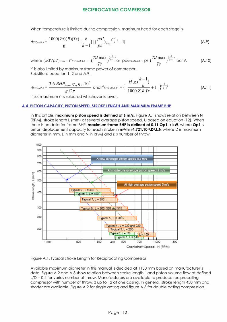
A.4. PISTON CAPACITY, PISTON SPEED, STROKE LENGTH AND MAXIMUM FRAME BHP In this article, maximum piston speed is defined at 6 m/s. Figure A.1 shows relation between N (RPM), stroke length L (mm) at several average piston speed, U based on equation (12). When there is no data for frame BHP, maximum frame BHP is defined at 0.11 Qp1. z kW, where Qp1 is piston displacement capacity for each stroke in m3/hr (4.721.10-8.D2.L.N where D is maximum diameter in mm, L in mm and N in RPM) and z is number of throw.
Figure A.1. Typical Stroke Length for Reciprocating Compressor Available maximum diameter in this manual is decided at 1130 mm based on manufacturer’s data. Figure A.2 and A.3 show relation between stroke length L and piston volume flow at defined L/D = 0.4 for varies number of throw. Manufacturers are available to produce reciprocating compressor with number of throw, z up to 12 at one casing. In general, stroke length 430 mm and shorter are available. Figure A.2 for single acting and figure A.3 for double acting compression.
Page : 12

RECIPROCATING COMPRESSOR
Figure A.2. Stroke length Against Piston Capacity Chart for Single Acting Compression
Figure A.3. Stroke length Against Piston Capacity Chart for Double Acting Compression
A.5. MECHANICAL EFFICIENCY The following figure shows mechanical efficiency, ηm
Figure A.4. Mechanical Efficiency of Reciprocating Compressor
Page : 13

RECIPROCATING COMPRESSOR
APPENDIX B. GAS PROPERTIES B.1. SINGLE GAS The following table presents single gas properties. There are MW (molecular weight), k (adiabatic
exponent), pcr (critical pressure ), Tcr (critical temperature) and MCp (=MW x Cp). Table 1. Pure Gas Properties Gas constant (R), specific heat (Cp) and k
Gas constant R = MW
314.8 (B.1)
Page : 14
RECIPROCATING COMPRESSOR
Specific heat Cp = 1
.−kkR
(B.2)
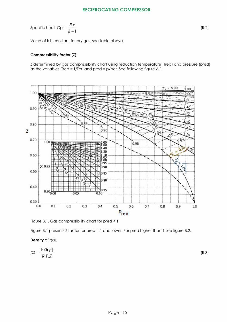
Value of k is constant for dry gas, see table above. Compressibility factor (Z) Z determined by gas compressibility chart using reduction temperature (Tred) and pressure (pred)
as the variables. Tred = T/Tcr and pred = p/pcr. See following figure A.1
Figure B.1. Gas compressibility chart for pred < 1 Figure B.1 presents Z factor for pred = 1 and lower. For pred higher than 1 see figure B.2. Density of gas,
DS = ZTRp..
)(100 (B.3)
Page : 15

RECIPROCATING COMPRESSOR
Figure B.2. Gas compressibility chart for pred higher than 1. B.2. MIXED GAS Gas constant (R), specific heat (Cp) and k of mixed gas Subscript (i) indicates partial of pure gas.
MW = ∑ (B.4) i
MWiMi )})((%01.0{
Where %Mi is partial mole of each individual gas in %
% Mi = ∑MMiMMi)(100
(B.5)
Where MMi is molal mass of each gas in kgmole or mols
MMi = MWiMgi
(B.6)
Where Mgi is mass of each gas in kg
k = ∑
∑− 314.8))(%(01.0
))(%(01.0MiMCpi
MiMCpi (B.7)
Gas constant R = MW
314.8
Page : 16

RECIPROCATING COMPRESSOR
Specific heat Cp = 1
.−kkR
Compressibility factor (Z) pcr = ∑ (B.8) ))((%01.0 pcriMi Tcr = ∑ (B.9) ))((%01.0 TcriMi Z factor determined using figure A.1 and A.2. Density of mixed gas,
DS = ZTRp..
)(100 (B.10)
B.3. WET GAS Gas shall be dry in centrifugal compressor to prevent internal parts and impeller from erosion due
to liquid particles. Gas condition shall be kept at little far from wet condition. Following table presents vapor pressure for some gases.
B.4. WET AIR Following steps describes how to determine properties of wet air.
1. Relative humidity RH in % 2. Dry bulb temperature tdb in C and then Tdb = 273 + tdb in K 3. Atmospheric pressure patm at bar A 4. From psychometric chart, determine wet bulb temperature twb and Twb = 273 + twb 5. From H2O saturated pressure table, determine saturated pressure at twb, pg 6. Partial pressure of H2O pw = 0.01 (%RH)(pg) 7. Partial pressure of dry air pa = patm – pg 8. Mole fraction of dry air Xa = pa / patm 9. Mole fraction of H2O Xw = pw / patm 10. Molal mass of wet air MW = (MWdry air)(Xa) + (MWH2O )(Xw) 11. MCp of wet air MCp = (MCp dry air)(Xa) + (MCp H2O)(Xw) 12. Gas constant R = 8.314 / MW 13. k k = MCp / (MCp-8.314) 14. Density DS = 100.patm / (R.Tdb)
Page : 17

RECIPROCATING COMPRESSOR
Table 2. Saturated pressure of H2O From % RH and tdb determine twb from following typical psychometric chart Figure B.3. Psychometric chart for air at 1 atm.
Page : 18
RECIPROCATING COMPRESSOR
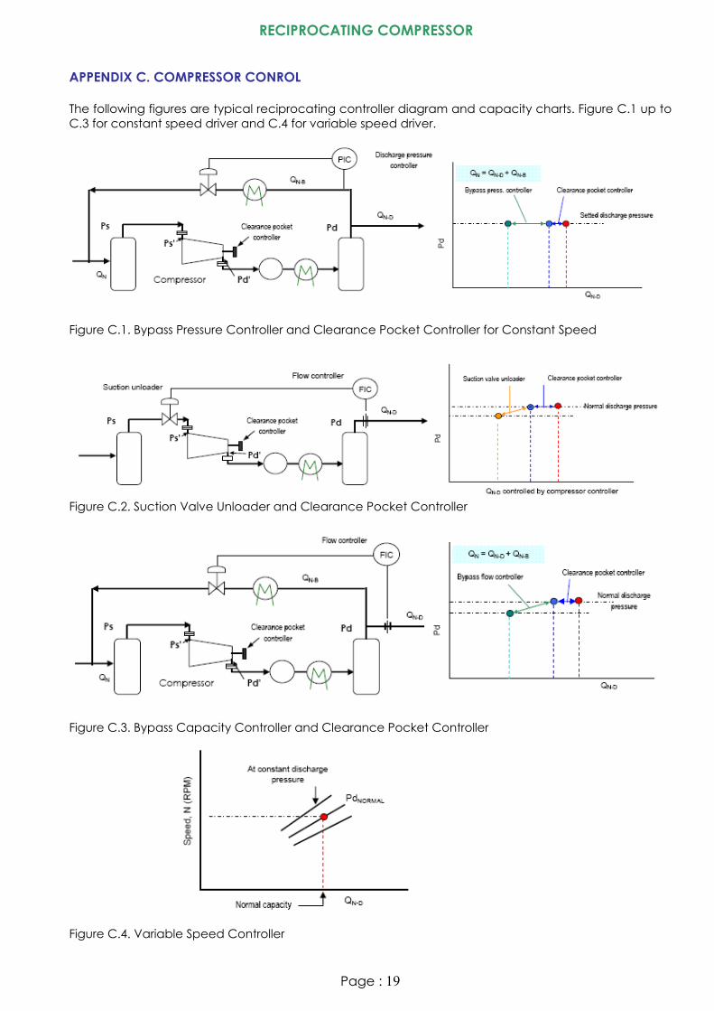
APPENDIX C. COMPRESSOR CONROL The following figures are typical reciprocating controller diagram and capacity charts. Figure C.1 up to C.3 for constant speed driver and C.4 for variable speed driver. Figure C.1. Bypass Pressure Controller and Clearance Pocket Controller for Constant Speed Figure C.2. Suction Valve Unloader and Clearance Pocket Controller Figure C.3. Bypass Capacity Controller and Clearance Pocket Controller Figure C.4. Variable Speed Controller
Page : 19