recent progress in heliogyro solar sail ......as a practical, advanced solar sail propulsion system...
TRANSCRIPT
RECENT PROGRESS IN HELIOGYRO SOLAR SAIL STRUCTURAL DYNAMICS
W. Wilkie (1), J. Warren (2), L. Horta (3) , J. Juang (4), S. Gibbs (5) , E. Dowell (6), D. Guerrant (7), D. Lawrence (8)
(1) NASA Langley Research Center, Mail Stop 230, Hampton, Virginia 23681-2199, USA, [email protected] (2) NASA Langley Research Center, Mail Stop 230, Hampton, Virginia 23681-2199, USA, [email protected] (3) NASA Langley Research Center, Mail Stop 230, Hampton, Virginia 23681-2199, USA, [email protected]
(4) NASA Langley Research Center, Mail Stop 230, Hampton, Virginia 23681-2199, USA, [email protected] (5) Duke University, Hudson Hall Box 900, Durham, North Carolina, 27708-0287, USA, [email protected]
(6) Duke University, 141 Hudson Hall, Durham, North Carolina, 27708-0287, USA, [email protected] (7) University of Colorado, 429 UCB, Boulder, Colorado, 80309-0429, USA, [email protected] (8) University of Colorado, 429 UCB, Boulder, Colorado, 80309-0429, USA, [email protected]
ABSTRACT
Results from recent National Aeronautics and Space Administration (NASA) research on the structural dynamics and control characteristics of heliogyro solar sails are summarized. Specific areas under investigation include coupled nonlinear finite element analysis of heliogyro membrane blade with solar radiation pressure effects, system identification of spinning membrane structures, solarelastic stability analysis of heliogyro solar sails, including stability during blade deployment, and results from small-scale in vacuo dynamics experiments with spinning high-aspect ratio membranes. A low-cost, rideshare payload heliogyro technology demonstration mission concept, used as a mission context for these heliogyro structural dynamics and solarelasticity investigations, is also described. 1 INTRODUCTION
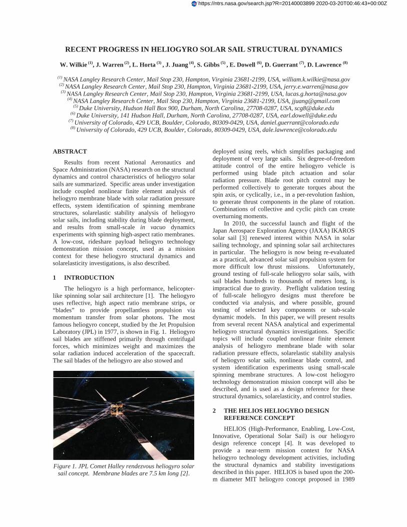
The heliogyro is a high performance, helicopter-like spinning solar sail architecture [1]. The heliogyro uses reflective, high aspect ratio membrane strips, or “blades” to provide propellantless propulsion via momentum transfer from solar photons. The most famous heliogyro concept, studied by the Jet Propulsion Laboratory (JPL) in 1977, is shown in Fig. 1. Heliogyro sail blades are stiffened primarily through centrifugal forces, which minimizes weight and maximizes the solar radiation induced acceleration of the spacecraft. The sail blades of the heliogyro are also stowed and
Figure 1. JPL Comet Halley rendezvous heliogyro solar
sail concept. Membrane blades are 7.5 km long [2].
deployed using reels, which simplifies packaging and deployment of very large sails. Six degree-of-freedom attitude control of the entire heliogyro vehicle is performed using blade pitch actuation and solar radiation pressure. Blade root pitch control may be performed collectively to generate torques about the spin axis, or cyclically, i.e., in a per-revolution fashion, to generate thrust components in the plane of rotation. Combinations of collective and cyclic pitch can create overturning moments. In 2010, the successful launch and flight of the Japan Aerospace Exploration Agency (JAXA) IKAROS solar sail [3] renewed interest within NASA in solar sailing technology, and spinning solar sail architectures in particular. The heliogyro is now being re-evaluated as a practical, advanced solar sail propulsion system for more difficult low thrust missions. Unfortunately, ground testing of full-scale heliogyro solar sails, with sail blades hundreds to thousands of meters long, is impractical due to gravity. Preflight validation testing of full-scale heliogyro designs must therefore be conducted via analysis, and where possible, ground testing of selected key components or sub-scale dynamic models. In this paper, we will present results from several recent NASA analytical and experimental heliogyro structural dynamics investigations. Specific topics will include coupled nonlinear finite element analysis of heliogyro membrane blade with solar radiation pressure effects, solarelastic stability analysis of heliogyro solar sails, nonlinear blade control, and system identification experiments using small-scale spinning membrane structures. A low-cost heliogyro technology demonstration mission concept will also be described, and is used as a design reference for these structural dynamics, solarelasticity, and control studies. 2 THE HELIOS HELIOGYRO DESIGN
REFERENCE CONCEPT
HELIOS (High-Performance, Enabling, Low-Cost, Innovative, Operational Solar Sail) is our heliogyro design reference concept [4]. It was developed to provide a near-term mission context for NASA heliogyro technology development activities, including the structural dynamics and stability investigations described in this paper. HELIOS is based upon the 200-m diameter MIT heliogyro concept proposed in 1989
https://ntrs.nasa.gov/search.jsp?R=20140003899 2020-03-20T00:46:43+00:00Z
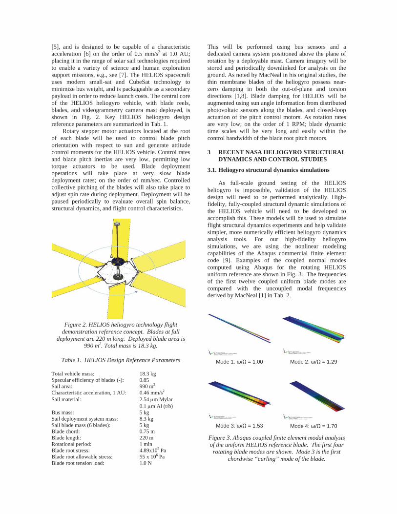
[5], and is designed to be capable of a characteristic acceleration [6] on the order of 0.5 mm/s2 at 1.0 AU; placing it in the range of solar sail technologies required to enable a variety of science and human exploration support missions, e.g., see [7]. The HELIOS spacecraft uses modern small-sat and CubeSat technology to minimize bus weight, and is packageable as a secondary payload in order to reduce launch costs. The central core of the HELIOS heliogyro vehicle, with blade reels, blades, and videogrammetry camera mast deployed, is shown in Fig. 2. Key HELIOS heliogyro design reference parameters are summarized in Tab. 1. Rotary stepper motor actuators located at the root of each blade will be used to control blade pitch orientation with respect to sun and generate attitude control moments for the HELIOS vehicle. Control rates and blade pitch inertias are very low, permitting low torque actuators to be used. Blade deployment operations will take place at very slow blade deployment rates; on the order of mm/sec. Controlled collective pitching of the blades will also take place to adjust spin rate during deployment. Deployment will be paused periodically to evaluate overall spin balance, structural dynamics, and flight control characteristics.
Figure 2. HELIOS heliogyro technology flight
demonstration reference concept. Blades at full deployment are 220 m long. Deployed blade area is
990 m2. Total mass is 18.3 kg.
Table 1. HELIOS Design Reference Parameters Total vehicle mass: 18.3 kg Specular efficiency of blades (-): 0.85 Sail area: 990 m2 Characteristic acceleration, 1 AU: 0.46 mm/s2 Sail material: 2.54 m Mylar 0.1 m Al (t/b) Bus mass: 5 kg Sail deployment system mass: 8.3 kg Sail blade mass (6 blades): 5 kg Blade chord: 0.75 m Blade length: 220 m Rotational period: 1 min Blade root stress: 4.89x10⁵ Pa Blade root allowable stress: 55 x 106 Pa Blade root tension load: 1.0 N
This will be performed using bus sensors and a dedicated camera system positioned above the plane of rotation by a deployable mast. Camera imagery will be stored and periodically downlinked for analysis on the ground. As noted by MacNeal in his original studies, the thin membrane blades of the heliogyro possess near-zero damping in both the out-of-plane and torsion directions [1,8]. Blade damping for HELIOS will be augmented using sun angle information from distributed photovoltaic sensors along the blades, and closed-loop actuation of the pitch control motors. As rotation rates are very low; on the order of 1 RPM; blade dynamic time scales will be very long and easily within the control bandwidth of the blade root pitch motors. 3 RECENT NASA HELIOGYRO STRUCTURAL
DYNAMICS AND CONTROL STUDIES
3.1. Heliogyro structural dynamics simulations
As full-scale ground testing of the HELIOS heliogyro is impossible, validation of the HELIOS design will need to be performed analytically. High-fidelity, fully-coupled structural dynamic simulations of the HELIOS vehicle will need to be developed to accomplish this. These models will be used to simulate flight structural dynamics experiments and help validate simpler, more numerically efficient heliogyro dynamics analysis tools. For our high-fidelity heliogyro simulations, we are using the nonlinear modeling capabilities of the Abaqus commercial finite element code [9]. Examples of the coupled normal modes computed using Abaqus for the rotating HELIOS uniform reference are shown in Fig. 3. The frequencies of the first twelve coupled uniform blade modes are compared with the uncoupled modal frequencies derived by MacNeal [1] in Tab. 2.
Mode 1: / = 1.00 Mode 2: / = 1.29
Mode 3: / = 1.53 Mode 4: / = 1.70
Figure 3. Abaqus coupled finite element modal analysis of the uniform HELIOS reference blade. The first four rotating blade modes are shown. Mode 3 is the first
chordwise “curling” mode of the blade.

Table 2. Uniform heliogyro blade frequencies FEM
frequency,Theoretica lfrequency, [1]
Mode Type
1 1st verti ca l 1.00 1.00
2 1st twis t 1.29 1.41
3 1st chord 1.53
4 2nd inplane 1.70 2.24
5 2nd chord 2.01
6 2nd twist 2.24 2.65
7 2nd vertica l 2.46 2.45
8 3rd chord 2.67
9 3rd twist 3.32 4.00
10 4th chord 3.41
11 3rd vertica l 3.88 3.87
12 5th chord 4.18 Out-of-plane (vertical) mode frequencies agree well, although significant discrepancies exist with the torsion and in-plane bending mode frequency predictions. Note that the Abaqus model is capable of capturing chordwise “curling” modes on the blade. These deflection modes would make control of a pure membrane heliogyro blade difficult, due to adverse couplings with solar radiation pressure, however the addition of battens should mitigate these issues [8]. Fully-coupled HELIOS blade structural dynamics finite element based simulations including solar radiation pressure have also been performed using Abaqus. An example case is shown in Fig. 4. Here the HELIOS uniform reference blade is freely rotating about the hub at an initial speed of 1 RPM. Radiation pressure is subsequently applied, followed by a blade collective pitch input of -20 degrees. For this case the sun angle is at -180 degrees relative to the positive spin axis, i.e., normal to and below the spin plane. Solar radiation pressure has been adjusted using the nominal 0.85 specular efficiency of the HELIOS sail. The blade root pitch input profile is shown in Fig. 4.a with the resulting tip torsional deflection shown in Fig. 4.b. The average blade tip twist between 25 and 75 revolutions is approximately 6.3 degrees which is comparable to the theoretical tip twist of 7.1 degrees predicted by MacNeal [8]. A small difference in tip twist is expected because of the relatively coarse, 4-element wide, chord-wise finite element discretization and that solar radiation pressure was not included in the theoretical solution. The center hub normalized angular velocity is shown in Fig. 4.c. The angular velocity increases as the blade is pitched due to the resulting solar radiation pressure induced torque about the spin axis. This is expected since the blade is freely spinning as it would be in flight. The average blade tip vertical displacement is shown in Fig. 4.d. The average blade tip vertical displacement before application of the root pitch input is
Figure 4. Fully coupled Abaqus time domain simulation
of HELIOS reference blade with solar radiation pressure at 1.0 AU.

approximately 0.286 meters which compares well with the MacNeal’s theoretical displacement of 0.281 meters [1]. Blade vertical deflection decreases over time as the blade and hub rotation rate, and resulting centrifugal forces, increase. Future studies will include nonuniform blade features and examine sensitivities of the finite element mesh discretization in more detail. 3.2. Solarelastic stability analysis
Heliogyro dynamics and solarelastic [10] stability studies are possible using the fully-coupled, finite element analysis methods described above, although these simulations are computationally. More efficient heliogyro analytical tools appropriate for rapid design and trade studies are needed. Our approach [11], previously explored by Natori [12], adapts rotating beam equations of motion developed for conventional helicopter rotor blade analysis for use with the heliogyro. These equations can be numerically solved using MATLAB-based codes, and although not applicable to all heliogyro flight conditions, can be used to evaluate heliogyro structural dynamic and stability behavior for many restricted, yet still relevant, cases. One such case is for a heliogyro operating at zero blade pitch angle with the spin axis pointed toward the sun. For this case, the equations of motion can be transformed into a second-order set of ordinary differential equations with constant coefficients valid for small deflections. The eigenvalues of this system can be evaluated as a function of fixed rotational speed and incident solar radiation pressure to determine operational stability boundaries for a given heliogyro design. Example stability behavior trends for the HELIOS uniform reference blade are shown in Fig. 5. Here the imaginary parts of the blade eigenvalues, corresponding to the normalized, i.e., per revolution, blade modal frequencies, are tracked as a function of effective solar radiation pressure. A blade flutter
Figure 5. Eigenvalue stability analysis of the HELIOS
uniform reference blade at the nominal rotational speed, = 1 RPM, and zero sun angle.
instability, signified by coalescence of the fundamental in-plane and torsional vibration modes, is indicated near an effective solar radiation pressure of 4.1 x 10⁻⁵ Pa. This corresponds to a heliocentric distance of about 0.5 AU. Blade dynamics in the vicinity of 1.0 AU (~0.91 x 10⁻⁵ Pa) are stable; at least for the nominal HELIOS rotational speed of 1 RPM. Further instabilities at higher solar radiation pressures are also indicated, most notably, a divergence instability near 5.3 x 10⁻⁵ Pa and a higher frequency flutter condition at 5.7 x 10⁻⁵ Pa, although such post-critical instabilities are not physically significant. Stability bounds for a given heliogyro blade design may also be mapped as function of rotor speed and effective solar radiation pressure. The stability boundary for the uniform HELIOS blade is shown in Fig. 6. Here, all unstable eigenvalues over the rotor speed range indicated have been tracked with the critical radiation pressure required to induce instability plotted against rotor speed. The lower bound in radiation pressure is indicated by the thick red line, with stable regions of rotational speed and radiation pressure lying below the line. Examination of this stability boundary plot indicates that at 1.0 AU solar radiation pressures (0.91 x 10⁻⁵ Pa) the HELIOS blade will encounter a solarelastic instability when rotational speed drops below approximately 0.6 RPM. Experimental verification of solarelastic stability characteristics would actually be an important goal of a heliogyro flight technology demonstration mission [2]. In practice, this could be accomplished by gradually reducing heliogyro rotation speed through the application of blade collective pitch; pausing periodically to experimentally evaluate the sub-critical changes in blade modal frequencies. As the dynamics of the heliogyro are relatively slow in real-time, stability boundaries may be approached slowly, and backed away from relatively quickly by re-application of blade collective pitch to increase the vehicle spin rate.
Figure 6. Solarelastic instability boundary of the
HELIOS uniform reference blade. Zero collective pitch and sun angle are assumed.
3.3. Stability during deployment
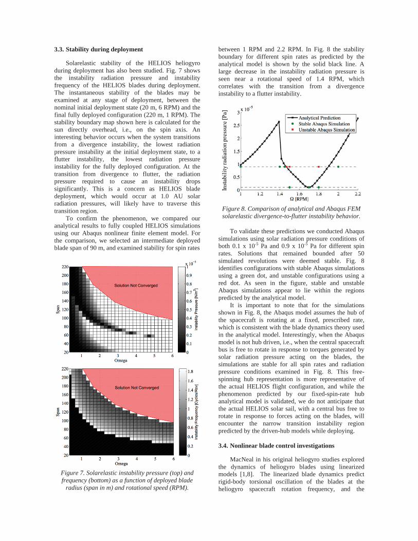
Solarelastic stability of the HELIOS heliogyro during deployment has also been studied. Fig. 7 shows the instability radiation pressure and instability frequency of the HELIOS blades during deployment. The instantaneous stability of the blades may be examined at any stage of deployment, between the nominal initial deployment state (20 m, 6 RPM) and the final fully deployed configuration (220 m, 1 RPM). The stability boundary map shown here is calculated for the sun directly overhead, i.e., on the spin axis. An interesting behavior occurs when the system transitions from a divergence instability, the lowest radiation pressure instability at the initial deployment state, to a flutter instability, the lowest radiation pressure instability for the fully deployed configuration. At the transition from divergence to flutter, the radiation pressure required to cause an instability drops significantly. This is a concern as HELIOS blade deployment, which would occur at 1.0 AU solar radiation pressures, will likely have to traverse this transition region. To confirm the phenomenon, we compared our analytical results to fully coupled HELIOS simulations using our Abaqus nonlinear finite element model. For the comparison, we selected an intermediate deployed blade span of 90 m, and examined stability for spin rates
Figure 7. Solarelastic instability pressure (top) and frequency (bottom) as a function of deployed blade
radius (span in m) and rotational speed (RPM).
between 1 RPM and 2.2 RPM. In Fig. 8 the stability boundary for different spin rates as predicted by the analytical model is shown by the solid black line. A large decrease in the instability radiation pressure is seen near a rotational speed of 1.4 RPM, which correlates with the transition from a divergence instability to a flutter instability.
Figure 8. Comparison of analytical and Abaqus FEM solarelastic divergence-to-flutter instability behavior.
To validate these predictions we conducted Abaqus simulations using solar radiation pressure conditions of both 0.1 x 10⁻⁵ Pa and 0.9 x 10⁻⁵ Pa for different spin rates. Solutions that remained bounded after 50 simulated revolutions were deemed stable. Fig. 8 identifies configurations with stable Abaqus simulations using a green dot, and unstable configurations using a red dot. As seen in the figure, stable and unstable Abaqus simulations appear to lie within the regions predicted by the analytical model. It is important to note that for the simulations shown in Fig. 8, the Abaqus model assumes the hub of the spacecraft is rotating at a fixed, prescribed rate, which is consistent with the blade dynamics theory used in the analytical model. Interestingly, when the Abaqus model is not hub driven, i.e., when the central spacecraft bus is free to rotate in response to torques generated by solar radiation pressure acting on the blades, the simulations are stable for all spin rates and radiation pressure conditions examined in Fig. 8. This free-spinning hub representation is more representative of the actual HELIOS flight configuration, and while the phenomenon predicted by our fixed-spin-rate hub analytical model is validated, we do not anticipate that the actual HELIOS solar sail, with a central bus free to rotate in response to forces acting on the blades, will encounter the narrow transition instability region predicted by the driven-hub models while deploying. 3.4. Nonlinear blade control investigations
MacNeal in his original heliogyro studies explored the dynamics of heliogyro blades using linearized models [1,8]. The linearized blade dynamics predict rigid-body torsional oscillation of the blades at the heliogyro spacecraft rotation frequency, and the

gyroscopic and inertia terms cancel exactly. The entire blade thus responds torsionally much like a flat plate, with the pitch at the blade tip closely tracking that commanded at the root. Unfortunately, this exact cancellation does not hold for the nonlinear blade dynamics undergoing large amplitude once-per-revolution (1P) cyclic root pitch commands, such as those that will be required (up to 45 degrees or more) to control the actual HELIOS flight vehicle. For these large amplitude conditions, blade torsional frequencies shift and can cause large amplitude torsional oscillations of the blade when coupled with 1P root pitch commands. Fig. 9 shows dynamic simulations using a nonlinear torsion-only finite element model [13,14] of the uniform HELIOS membrane blade at two cyclic pitch command amplitudes. Nonlinear torsional response to a 20° cyclic pitch input is shown at the top of Fig. 9. Although not all higher harmonics are completely damped, tip oscillations are reasonably bounded. In contrast, the nonlinear response for a 25° cyclic root pitch command, shown in the bottom of Fig. 9, is seen to be unacceptably large, even though the root cyclic pitch amplitude is only 5° greater than the 20° case. The first torsional mode frequency has also shifted below the 1P cyclic root pitch control frequency due to amplitude-dependent non-linearities. One approach for mitigating undesirable shifts in torsion modal frequencies is to increase the centrifugal
Figure 9. Nonlinear once-per-revolution (1P) cyclic
pitch torsional responses of a uniform membrane blade: (top) 20° root pitch amplitude, (bottom) 25° root pitch
amplitude.
stiffening of the blade. This may be accomplished using a larger tip mass, although this additional mass should be concentrated at the twist axis rather than distributed across the blade chord to minimize increases in the tip rotational moment of inertia. Centrifugal stiffening may also be increased by redirecting the spanwise tension acting along the blade to the leading and trailing edges. In practice, this load distribution could be accomplished using reinforced tension carrying elements at the edges of the blade, e.g., cables or ribbons, with periodic spanwise attachment of membrane sail panels to the edge members. This approach, with its enhanced torsional stiffening, was ultimately adopted for the very large, 15 km diameter JPL heliogyro studied in the 1970s [2]. For edge stiffened blades, the resulting structural dynamics more closely resemble those of a spinning rope ladder, instead of a simple uniform membrane sheet. Fig. 10 shows a simulation of the rope-ladder blade using both edge stiffeners and additional tip mass equal to approximately 10% of the idealized uniform membrane blade mass. Response of the edge-stiffened blade to the 25° cyclic pitch command is now seen to be stable, with blade flatness and settling time greatly improved. The blade is also well behaved for a much larger 60° cyclic profile. This initial work suggests that non-linear effects of torsion mode frequency shifts can be avoided and reasonable blade flatness maintained with modest structural design changes.
Figure 10. Nonlinear 1P cyclic pitch torsional response
of an edge-stiffened blade: (top) 25° root pitch amplitude, (bottom) 60° root pitch amplitude.

3.5. In vacuo spin dynamics experiments
Although exact dynamic testing of full-scale spinning heliogyros is not possible on the ground due to the presence of gravity, experiments on small sub-scale spinning membrane systems can be performed under one-g. The results from these experiments can be used for validating heliogyro structural dynamics models and for building confidence in analytical simulations of the full-scale vehicle. Such experiments were proposed during the JPL heliogyro study of the 1970s, although no experiments were performed. [15] Some earlier heliogyro spin dynamics validation experiments were attempted in air by MacNeal, but were severely complicated by atmospheric effects. [8] As an inexpensive pathfinder experiment, we have recently begun testing small-scale spinning membrane blades in our 2.5-m diameter vacuum sphere using a system constructed around low-cost, commercially available radio-controlled helicopter components. Fig. 11 shows the spin test apparatus in the vacuum chamber during initial testing. A hub-mounted videogrammetry camera system is used to recover displacement information from the spinning membrane blades. A rotational speed of 125 RPM ( = 2.08 Hz) was found to produce the smallest vibration levels and was used for the example shown here. Our ability to track targets varied depending on the pitch angle of the blade. In this example, 17.3 seconds of time history data was extracted for six targets. Out-of-plane displacement component time histories for all six targets are shown in Fig. 12. An eigensystem realization algorithm (ERA) [16] was used with the videogrammetry time history data to recover the system modes and frequencies. An Abaqus finite element model (FEM) was also used to predict the
Figure 11. Heliogyro membrane spin dynamics test apparatus in vacuum chamber: a) hub and camera assembly with rigid checkout blades; b) spin test
apparatus with 0.5 m Kapton membrane blades prior to spin up; c) fixed-frame camera view of spin test
apparatus in vacuum at 120 RPM; d) rotating frame camera view of the spinning membrane blade.
0 2 4 6 8 10 12 14 16 18
-3
-2
-1
0
1
2
3
4
5
Time (sec)
Out
-of-
Pla
ne D
ispl
acem
ent (
mm
)
data1data2data3data4data5data6
Figure 12. Videogrammetry measurements of out-of-
plane deflections for the 0-degree pitch spinning membrane blade. Rotational speed is 125 RPM ( =
2.08 Hz).
dynamics of the rotating membrane blade under gravity and centrifugal forces. The FEM accounts for the root offset of the blade from the center of rotation, although hub flexibility and mounting dynamics are not included. Modal frequencies and damping values identified for the first six blade modes are compared with predicted FEM frequencies in Tab. 3. Confidence levels for the identified modes are also shown. Only the first two blade modes were identified with a high degree of confidence. Fig. 13 shows a plot of the mass weighted cross-orthogonality between the experimental data and FEM results. Plotted along the ordinate are ERA values versus Abaqus along the abscissa. Unity values are indicated in black. The first identified experimental mode shape was the fundamental torsion mode at a normalized frequency of 0.99 (0.99 P), with the second mode being the fundamental out-of-plane bending mode at 1.14 P. Mode similarities are reflected in the high orthogonality value for the second identified mode versus the first predicted Abaqus mode, although mode order is switched between test and analysis.
Table 3. Experimentally identified modal properties for the 0-degree pitch spinning membrane blade.
Rotational speed is 125 RPM ( = 2.08 Hz).
FEMMode
No.Freq. ( )
Damp. (%)
Conf. (%)
Freq. ( )
1 0.99 0.06 100 1.032 1.14 0.09 66.2 1.443 1.61 0.72 6.0 2.404 1.87 2.04 4.1 4.055 1.96 1.21 8.1 5.496 2.94 1.26 4.8 7.06
Identified Modes

1 2 3 4 5 6
0.99
1.14
1.61
1.86
1.96
2.94
Mode Number
ERA
Iden
tifie
d Fr
eque
ncy,
P
FEM Frequency,P
1.03
1.43
2.40
4.05
5.49
7.05
0
0.2
0.4
0.6
0.8
1
Figure 13. Mass-weighted modal cross-orthogonality results for the experimentally identified blade modes
and Abaqus FEM modes.
Future modifications to the FEM and experimental apparatus should improve correlation. Modeling improvements will include the addition of mount and hub structural dynamics. Future spin dynamics experiments will be performed in our larger 2.5 m x 5 m thermal vacuum chamber under higher vacuum conditions. This should minimize unsteady aerodynamic effects more fully, allowing us to better measure blade transient dynamics and damping behavior. 4 SUMMARY AND CONCLUSIONS
Our detailed analytical and experimental investigations into the coupled structural dynamics of heliogyro membrane blades have been encouraging and, to date, have revealed no intractable stability and control issues for the heliogyro solar sail concept. Significant accomplishments include: Development of a coupled nonlinear finite element
heliogyro structural dynamics modeling capability including solar radiation pressure;
Development of a computationally efficient analytical solarelasticity modeling capability useful for heliogyro stability studies, including stability during blade deployment;
Development of a small-scale heliogyro dynamics ground testing capability.
Furthermore, we conclude that: Certain deployment instabilities seen when using
fixed spin rate heliogyro blade dynamics models are artefacts of the fixed spin rate assumption. These instabilities disappear when the central bus of the heliogyro is permitted to spin in response to blade forces.
Redirecting centrifugal tension loading to the blade leading and trailing edges, or adding tip mass to increase centrifugal stiffening, improves large-amplitude cyclic pitch response of the blades.
Ultimately, an actual spaceflight validation mission will be needed to prove feasibility of the heliogyro solar sail concept and retire risk. Given a near term effort to advance the technology readiness of critical systems,
most notably blade dynamics simulation capabilities, deployment mechanisms, solarelastic flutter dynamics and control systems including damping augmentation, and relevant ground test demonstrations, a HELIOS or HELIOS-like, low-cost heliogyro flight demonstration could be conducted in the relatively-near future. 5 REFERENCES
1. MacNeal, R., “The Heliogyro: An Interplanetary Flying Machine,” NASA Contractor Report CR 84460, June 1967. 2. MacNeal, R., Hedgepeth, J., “Helicopters for Interplanetary Space Flight,” 34th National Forum of the American Helicopter Society, Washington, D. C., May 1978. 3. Mori, O., et al., “Overview of IKAROS Mission,” in: Macdonald, M. (Ed.), Advances in Solar Sailing, pp. 25-43, Springer-Praxis, Springer Berlin Heidelberg, 2014. 4. Wilkie, W., et al., “Heliogyro Solar Sail Research at NASA,” in: Macdonald, M. (Ed.), Advances in Solar Sailing, pp. 631-650, Springer-Praxis, Springer Berlin Heidelberg, 2014. 5. Blomquist, R., “Design Study of a Solid-State Heliogyro Solar Sail,” M.S. thesis, Massachusetts Institute of Technology, Cambridge, MA, September 1990. 6. McInnes, C., Solar Sailing: Technology, Dynamics and Mission Applications, 1st ed., Springer-Praxis, Chichester, UK, 1999. 7. Macdonald, M., McInnes, C., “Solar Sail Science Mission Applications and Advancement,” Advances in Space Research, 48 (2011) 1702–1716. 8. MacNeal, R., “Structural Dynamics of the Heliogyro,” NASA CR-17445A, 1971. 9. Dassault Systèmes Simulia Corp., Providence, RI, USA. 10. Dowell, E., “Can Solar Sails Flutter?,” AIAA Journal, Vol. 49 (2011) 1305-1307. 11. Gibbs, S., Dowell, E., “Solarelastic Stability of the Heliogyro,” in: Macdonald, M. (Ed.), Advances in Solar Sailing, pp. 661-665, Springer-Praxis, Springer Berlin Heidelberg, 2014. 12. Natori, M., Nemat-Nasser, S., Mitsugi, J., “Instability of a Rotating Blade Subjected to Solar Radiation Pressure,” AIAA 30th Structures, Structural Dynamics and Materials Conference, April 1989. 13. Guerrant, D., Lawrence, D., Wilkie, W., “Performance of a Heliogyro Blade Twist Controller with Finite Bandwidth,” AIAA/AAS Astrodynamics Specialist Conference, August 2012, Minneapolis, MN. 14. Guerrant, D., Lawrence, D., “Heliogyro Solar Sail Blade Twist Stability Analysis of Root and Reflectivity Controllers,” AIAA Guidance, Navigation and Control Conference, August 2012, Minneapolis, MN. 15. “Solar Sail Technology Readiness Report,” 720-1, Jet Propulsion Laboratory, July 1977. 16. Juang, J.-N., Horta, L., Phan, M., “System/Observer/Controller Identification Toolbox,” NASA TM 107566, February 1992.