recent development of construction techniques...
TRANSCRIPT
RECENT DEVELOPMENT OF CONSTRUCTION TECHNIQUES IN CONCRETE BRIDGES
Man-Chung Tang, P.E., Exec. V.P., DRC Consultants, Inc., N.Y. Former V.P. and Ch. Eng., Dyckerhoff & Widmann, Inc., N.Y.
It is intended to report about various construction methods developed for concrete bridges. They can be briefly listed as f ollows : l) Free Cantilevers, 2) Segmental on Sliding Form, 3) Spanwise Segmental, 4) Incremental Launching, 5) Stage Casting, 6) Cantilever on Falsework, 7) Cable-Stayed Cantilever, 8) Segmental with Gantry or Truss. Most of these methods have been employed in the United States for the first time within the last 5 years. Some are under construction right now. Depending on site conditions and requirements, combinations of these methods can be used. This paper will discuss the advantages as well as the design problems of these methods.
Introduction
The decision of how a bridge should be built depends mainly on local conditions. These include cost of material, available equipment, allowable construction time and environmental restrictions. Since all these vary with location and time, the best construction technique for a given structure may also vary.
In this paper, several popular construction techniques now being used in the United States and Canada are discussed in more detail. Some special methods which are now being used in other parts of the world are also briefly mentioned.
c ............... r- ........ .:, ... ...... ~ ,.. ___ .... .. .. -.&..! - -'I"-''- vUlll;I l'll;;V 'i;; I ' \JVll.;>1,,.I Ul...1..IUll
The practice of free cantilever construction is quite old. However, it was first systematically developed for concrete by Finsterwalder and was applied in 1952 for the construction of the Lahn Bridge in West Germany. The basic principle of this method is to build the bridge in segments cantilevering from the pier in a balanced
172
manner. The segments under construction are supported by the already completed portion of the bridge. Construction starts by casting on top of a pier a short portion of the superstructure. Two form travelers (Fig. l) are then erected on this pier table. The form travelers carry the formwork and construction loads for the next segment and advance from segment to segment as construction proceeds. The segments are usually 15' (4.5m) to 16.5' (5m) long. Smaller segments under 10' (3 meters) have also been used.
Each working cycle of a cantilever segment consists of the following steps:
l. Move the form traveler ahead. This also brings the outside forms along.
2. Place rebars and tendons in webs and bottom slab.
3. Pull inside formwork forward. 4. Place rebars and tendons in top
slab. 5. Pour concrete after adjusting the
formwork. 6. After concrete has reached the
predetermined strength, stress tendons and the next cycle can start. Repeat the cycle.
In most cases, the segments are poured in weekly cycles. Shorter cycles, down to lY, to 2 days are possible if steam curing or special concrete admixture is used. In those cases, however, very strict quality control at the jobsite must be maintained.
The advantages of cantilever construction are:
1 C' "3 , ,.. ..... ... ,.. ..... 1.. ~ ,. .... ..... ... .... ......... '~ ...... ,.., 1 \A I o.J"- ""-'I I' I J II V \o I \,,; '-t U I I \,;;; U •
2. The repetitive cycle of the same work in each segment produces high labor efficiency.
3. Form travelers, equipped with hydraulic and mechanical devices for form stripping, moving, and resetting, mechanize the forming work.
4. Each segmental form is used many times, resulting in reduced forming

CENTERJACK
" .. I
I t==- -r-,. " l ~1'.;.";:ll:~ ==::::=.: I
f} CANTILEVER
FRONTAL UPPER (~,
I I ADDITIONAL FDRMWORK
l [] CONNECT ION FOR
~- L -BAR COMBIN ATIONS
I mTRESSIN OAR
I REAR GANG-BOARD
Fig. l
material cost.
These advantages have made prestressed concrete bridge construction most economical for the following conditions:
l. Terrain that makes falsework construction very expensive and difficult or even impossible.
2. Clearance requirements for ship, rail or street traffic that forbids falsework.
3. Length of bridge which allows many repetitive segment cycles taking advantage of labor efficiency and small formwork material and elimination of falsework cost.
The first long-span bridge constructed by this method in North America is the Knight Street Bridge (Fig. 2) in Vancouver with 360' (llOm) span.
j E -
BOTTOM FRAME WORK
Form Traveler
WORKING PLATFORM *
FRONTAL LOWER WORKING PLATFORM
~
r
52 m --~.r----------- 110 m -------- ----52 m----<
pig. 2 Knight Street Bridge
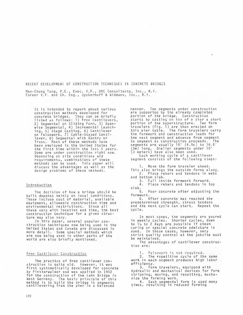
The Pine Valley Creek Bridge (Fig. 3) in California is the first in the United States. This spectacular bridge with a 450' (137m) main span and 350' (107m) high piers marks a successful introduction of the cantilever bridge construction to the United States. After the Pine Valley Creek Bridge, there have been a number of free cantilever bridges in the United States and Canada: the Kipapa Stream
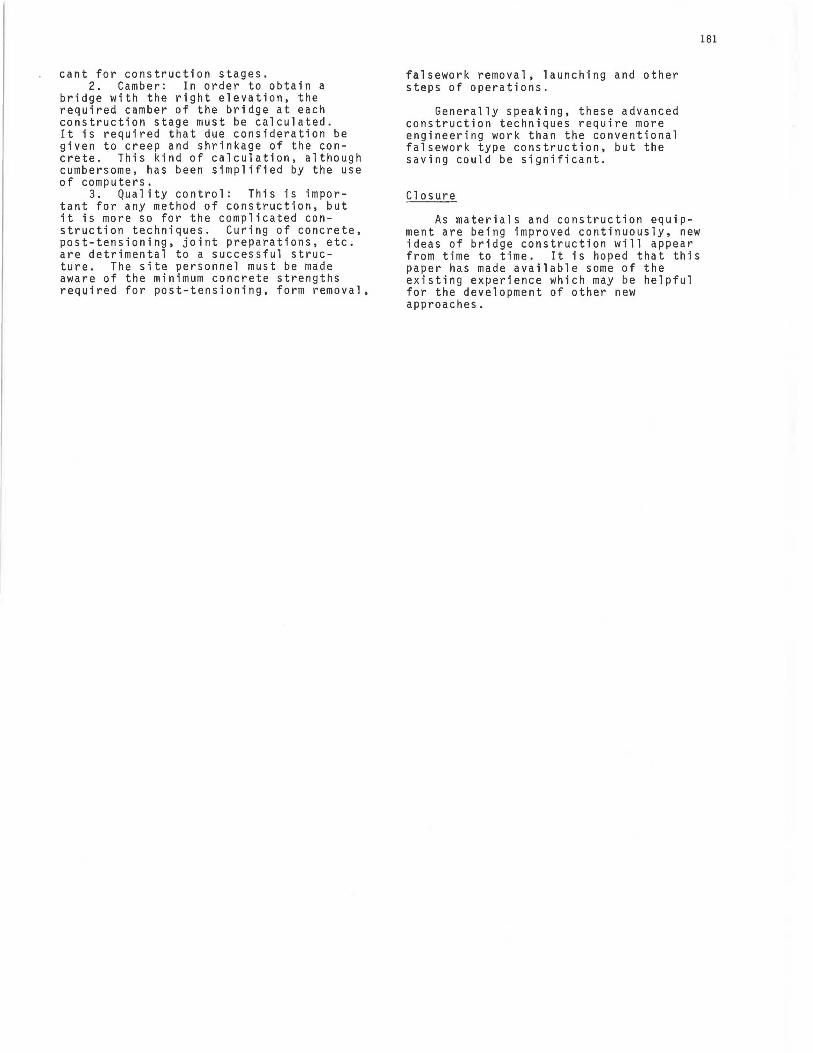
Bridge in Hawaii, the Grand Mere Bridge in Quebec and the world's record span of Koror-Babelthuap Bridge (Fig. 4) in the U.S. Trust Territory. This latter structure with its 790' span connects the two islands of Koror and Babelthuap. The tidal current of the strait prohibits the construction of any intermediate piers. Cantilever construction is the only possible method for this structure.
173
174
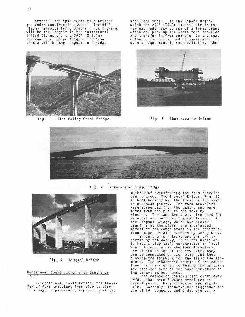
Several long-span cantilever bridges are under construction today. The 640' (l95m) Parrotts Ferry Bridge in California will be the longest in the continental United States and the 700' (213.4m) Shubenacadie Bridge (Fig. 5) in Nova Scotia will be the longest in Canada.
Fig. 3 Pine Valley Creek Bridge
spans are small. In the Ki papa Bridge which has 250' ( 76. 2m) spans, the transfer was made easy by use of a large crane which can pick up the whole form traveler and transfer it from one pier to the next without dismantling and reassemblage. If such an equipment is not available, other
Fig. 5
I 1
Shubenacadie Bridge
Fig. 4 Koror-Babelthuap Bridge
Fig. 6 Siegtal Bridge
Ca nt i lever Con str uc t ion with Gantry or Truss
In cantilever construction, the transfer of form travelers from pier to pier is a major expenditure, especially if the
methods of transferring the form traveler can be used. The Siegtal Bridge (Fig. 6) in West Germany was the first bridge using an overhead gantry. The form travelers were suspended from the gantry and were moved from one pier to the next by winches . The same truss was also used for material and personal transportation . In the Si~gtal Bridge, which has rocker bearings at the piers, the unbalanced moment of the cantilevers in the construction stages is also carried by the gantry.
Since the form travelers are transported by the gantry, it is not necessary to have a pier table constructed on local scaffolding. After the form travelers are placed on top of the new pier, they ~=~ b~ ~c~~e~tc~ t: ~a~h ~th~~ ~~d t~~: provide the formwork for the first two segments. The unbalanced moment of the cantilever is transferred to the gantry by tying the finished part of the superstructure to the gantry at both ends.
This met~od of constructing cantilever bridges has been further developed in recent years. Many varieties are available. Recently Finsterwalder suggested the use of 10' segments and 2-day cycles, a

procedure which might be convenient for many structures.
The writer has suggested to use a double truss running underneath the bridge instead of the overhead gantry. The advantage of using this double truss is that longer segments can be cast because the formwork is supported directly by the truss. Thirty foot (9m) segments are usually found economical for this scheme.
Either the overhead gantry or the underlying trusses can be used for both cast-in-place and precast construction. Because the precast units have to be transported and erected in single pieces, their weight must be kept to a manageable limit. Therefore, the segments in the precast scheme are usually shorter, mostly between 5' to 8' (l.5m to 2.4m).
The Kishwaukee River Bridge (Fig. 7) in Illinois is a precast segmental bridge to be erected by means of a gantry. The typical segments are f feet (2.lm) long and all tendons in the bridge are straight.
Fig. 7 Kishwaukee River Bridge
Cantilever Construction with Tem porary Sup por t s
If the bridge span is too short for free cantilever construction and the project is too smal 1 to warrant the use of a gantry, the bridge still can be built advantageously by the cantilever method but with temporary supports. The Miller Creek Bridge (Fig. 8) at Vail Pass in Colorado is a good example of this type of construction. To eliminate the work of reassemblage of form travelers from pier to pier, the construction of the bridge starts from both abutments and continues segmentally towards the center of the bridge. When the cantilever has reached half the span length, the weight of the subsequent segments is carried by temporary supports which are usually placed under every second segment. These temporary supports can be removed and reused for the next span after the next cantilever has reached approximately half span.
The method is economical if local supports are allowable and the superstructure is not very high above the ground. It retains practically all the advantages of free cantilever construction. In
Fig. 8 Vail Pass Bridge
L'™~ r
Fig. 9 Use of Staying Cables
addition, the finished portion of the superstructure can serve for the transportation of material and personnel during construction.
Cantilever with Staying Cables
Sometimes, temporary support as described in the last paragraph may not be permitted under local circumstances due to environmental restriction, very high piers or bad soil conditions, In this case staying cables can be used to replace the temporary supports (Fig. 9). This method has been used successfully for many bridges in Europe; one of these is the Berlin Bridge in West Germany. In North America this method has not yet been used. However, a similar system to this construction is actually the cable-stayed bridge, for example, the Pasco-Kennewick Bridge in Washington . This is a precast concrete bridge constructed in the cantilever method, and supplemental cables are used to erect the precast segments which weigh up to 300 tons a piece. The Hoechst Bridge in West Germany is an alternative in the cast-in-place method.
175

176
Span-wise Construction
If the bridge span is relatively sma l"l, very often a much larger pour, say one whole span, can be justified. In this case, putting the construction joints at about the inflection point appears to be logical. Every time, one span of the bridge from inflection point to inflection point can be constructed at the same time. The formwork can be removed after the post-tensioning of this span has been completed. In this way only one set of formwork equal to the length of one span is required for the whole bridge. This scheme is very suitable for multi-span bridges. One of the first of this type is the Elz Valley Bridge (Fig. 10)
Fig. l 0 Elz Valley Bridge - Spanwise Construction
in West Germany. This bridge was 330' (lOOm) above the valley, which ruled out any kind of falsework support. A form carrier was used to cast one span each time. This early scheme had the shape of a mushroom. The cross-section for this 123' (37.5m) span and 100' (30m) wide bridge was solid and varied from l '-10" (0.56m) to 8'-0" (2.5m). The form carrier of this bridge was understandably quite heavy.
Fig. 11 Fichera Bridge
However, the construction was speedy. After the initial assemblage and startup, a two-week cycle for each span was achieved.
After the Erz Valley Bridge had been successfully constructed by this method, a number of other bridges were built in the same manner, notabl y the Fichera
Bridge (Fig. 11) in Italy and the Brenner Autobahn Bridge (Fig. 12) in Aµstria. Several new bridges in other parts of the world are under construction by a similar method (Fig. 13-15).
If the piers are not very high, falsework can be used instead of the form carrier. This method was used for several smaller bridges in the United States and Canada. For example, the Cumberland Bridge in Maryland, the
Fig. 12 Brenner Autobahn Bridge
Clayton County Bridges (Fig. 16) in Georgia and the Bedford By-Passes No . l and No. 2 (Fig. 17) in Nova Scotia are designed and constructed in this method .
To allow for a simple construction in this type of bridge, the layout of tendons should follow a specific pattern so that all tendons can either be termi-

nated or coupled and extended at the construction joint. However, after the construction of so many bridges of this
type, various details are available to satisfy these requirements.
Fig. 13, a & b Ohlstadt Bridge, West Germany - Bridge & Formwork System
Fig. 14 Elevated Highway, Milan Fig. 15 Expressway, Rome-Florence
Fig. 16 Clayton County Bridge Fig. 17 Bedford By-Passes Georgia
177

178
Segmental Construction on Sliding Forms
When a bridge span becomes larger, span-wise construction becomes inefficient or difficult due to the large quantity of concrete which has to be cast at one time. An alternative to this is the construction using sliding forms.
The bridge span is divided into a number of segments which vary between 40' (12m) and 75' (23m) in length. The main post-tensioning of the span will be done after one span is finished, which is in principle the same as the span-by-span construction. However, partial post-tensioning after construction of each segment must be provided to take care of any bending
' stresses that may occur due to falsework settlement or other reaons. The best length of segments depends on the local conditions and the size of the bridge. The idea is to limit the quantity of material to be handled in each segment to a manageable dimension. Normally a one-week cycle for each segment is reasonable except for the first few segments.
Fig. 18 Eel River Bridge
The Eel River Bridge (Fig. 18) in northern California was the first in the United States constructed by this method. The segments were about 40' (l2m) long. After each segment was poured, the outside formwork was pushed ahead to the next segment, and the inside formwork would follow after the reinforcement and post-tensioning tendons were installed. The construction time had been slightly over l week per cycle for a bridge segment. ThP tnt;il l<>nni"h nf f;ilc:<>wnl"lt "'"" "hn11t 2~i ~~-i~e-i~{~i ~~n~i~-~~ - i~e--~~i~~;:-and the formwork was about 3% of the total contact form area. Considering the high cost of form- and falsework for bridge construction, the saving in this method is evident.
An alternate to this method is shown in (Fig. 19) by using a truss and temporary supports.
Stage Casting
Another alternative to the span-wise construction for longer spans is the stage casting method. In the segmental method on sliding forms, the bridge is separated into segments by vertical construction joints. In the stage casting method the bridge is separated by horizontal ~onstruction joints into horizontal slices. For medium-span bridges the falsework for a whole span can be very expensive due to the weights of the bridge, especially if the bridge is high and a gantry has to be used. In order to reduce the weight which is supported by the truss or falsework, the bridge can be designed in such a way that part of it is supported by the previously built parts.
The Denny Creek Bridge is the first bridge designed in this way. It is 2600' (793m) long and has regular spans of 188' (57.3m). The highest pier is about 180' (54.9m). Because of the high piers and because of the soil conditions at the site, falsework is not permitted. Therefore the writer suggested that the bridge be constructed in stages. (Fig. 20)
The bottom part of the box, the U-
Fig. 19 Sliding Form on Truss
shaped bottom slab and the webs of this bridge, is designed to carry the load of the middle part of the top slab, and the closed box will carry the wing slab. In this way, the truss is required to carry only the weight of the "U" which is approximately l/3 of the weight of the bridge. After the "U" has been post-tensioned, the truss can be advanced to the next span. (Fig. 21) The top slab of the "U" will be constructed by means of a sliding form 1.1h~rh +~~\1olc ~nc~~o +ho hnv nno ~~~n .... . - •• ... • - ..... ' - • '. - • .... ... ... • '... .... .... '" u '.... - ,.. ... '.
after the truss, and then the wing slab will be cast by another form carrier one span after the inside form so that all three parts of the cross-section can be under construction at the same time, but at different locations. It is estimated thai a two-week cycle for each span can be achieved after the learning period of a few spans.

STAGE I I I
STAGE II STAGE III
~ :u,TAGE
179
STAGE I
Fig. 20 & 21 Denny Creek Bridge - Stage Construction
Incremental Launching Method
The method as developed by Leonhardt has been applied very successfully to many bridges all around the world. The first of this type of bridge in the United States was built in Indiana {Fig. 22), and it can be anticipated that this method will gain popularity in the United States.
This method can be classified as segmental construction because it is cast in 40'-80' (12m-24m) segments but all at the abutment. It is very similar to an extrusion method used by the aluminum manufacturers. After each segment is cast, the bridge will be pushed out from the abutment so that the next segment can be cast right against the previous one. To simplify the construction, it is normally done in castin-place method and the formwork is two segments long. While the webs and top slabs of one segment are being cast, the bottom slab of the next segment will be poured simultaneously so that the use of the labor force can be more efficient. A steel girder is attached to minimize the cantilever moment at the front end of the bridge. {Fig. 23) The posttensioning of the bridge during launching is mainly centrical post-tensioning because the bending moment in these stages are reversible due to the everchanging support conditions.
The launching of the bridge is done by mechanism at the abutment. A simple method is to first lift the bridge slightly off the abutment by a hydraulic jack and use another hydraulic jack to push the bridge forward. Pulling devices have also been used for some recent bridges. Teflon pads and steel plates are used at the piers to reduce friction to about 2 to 3% of the vertical load.
There are certain restrictions for this type of construction. It is evident that the foundation at the abutment must be very sturdy. The superstructure must be either completely straight or has a constant curvature. Temporary supports are required for spans over about l 60' ( 49m), and the bridge should be slightly deeper than a comparable bridge built by other methods.
~1~JC3 ~3 ll\~' 4 187'-0" '3'6°1 ~ ¥lo • .~ .... J >·
Fig. 22 Wabash River Bridge Indiana
casting area
~_,,.1 ~ temporary suppotts
~-h-i n_g__.1~lLo_s_e __ tL-----~LL._
Fig. 23 Incremental .Launching
Recently, there have been bridges with more difficult geometric configurations being constructed in Europe by ·this method. For certain given local conditions, this may be feasible or even economical.

180
Cu111L> i r1d Li ur1s uf 01 fferent Methods
The various construction methods discussed can be combined in different ways to suit the local situation. For example, in the Koror-Babelthuap Bridge, while the free cantilever construction was the only method for the main span, the side spans of this bridge were constructed on falsework because the ground level at this area was very close to the soffit of the bridge. Taking further advantage of this local condition, the ground level at the side spans was built up to approximately the soffit level of the bridge with sand-fill and only a very light falsework was required for this part of the bridge. This was especially advantageous because lumber was very expensive in this area and the only available local lumber supplier produces only two-byfours.
t CANT. CONSTIL CANT.CONSTR.
]ffi"' TEMP. SUPPORTS
CANT.CONSTR. CANT.CONSTR.
~,.---t-t _[ _t_t_[_t -t _TI_t _t r-
t°N FALSEW ~
~111111IT JI m 11111)1 FALSEWORK
t CANT. CONS TR . ,.I,. C. C t c. c .,IJ:ANT . CO NSTR. t
'9'tt[ [ 1Ifttr Fig. 24 Vail Pass Bridges
Another example of a combination mPthnrl ic +hQ \l~il D~cc R~i~noc {~in ?A\ -- · -· · - -· · - ·-·· ·--- - · ·- :;J---· \' •::J• ..... ,
There are four bridges of similar size in the same project, however, the topography of these bridges differs. After careful consideration of all local conditions, different construction methods were proposed for these bridges using free cantilevers, temporary supports and falsework construction. It was significant that all four bridges were finished in one season.
An ingenious application of two combined construction methods is the MainFlingen Bridge in West Germany. This is a girder bridge with a main span of 436' (133m) over a navigational channel. This type of bridge has traditionally been built by the free cantilever method. However, the design and construction team used a combination of cable stays and incremental launching so that the bridge was built in segments at both abutments and launched incrementally over the main span simultaneously.
A similar but significant construction is now under way for the Danube Bridge in West Germany. This cablestayed bridge will be built by the incremental launching method on temporary supports. The towers and cables will be constructed after the bridge girder has been finished. This combination of methods is in sharp contrast to the last bridge. Th i s is a cable-stayed bridge but built on falsework as a girder bridge, while the Main-Flingen Bridge is a girder bridge but uses temporary cable stays.
This last example shows that the method of construction of any given bridge should be left to the contractor to decide . The best method or the most economical construction depends very much on the experience of the contractor, the equipment he can have available, the environmental constraints of the bridge site, etc. which are mostly unknown to the design engineer who has to work on the structural analysis normally 4 to 5 years before the bridge was out for tender. To restrict the contractor to a specific method using specific types of equipment could only result in a very expensive bridge and very often to inferior quality because this may or may not be in the experienced area of the success-ful bidder. As an engineer or as an owner, the final product -- the bridge, is of concern but not the intermediate stages of how the bridge is built.
Spe cial Requirements in Advanced Construction Techniques
It is understandable that a certain amount of engineering work is involved in applying any advanced construction technique. A bridge that is built in several stages or in many segments does not behave exactly the same way as a bridge that is built totally on falsework. The reinforcement and posttensioning requirements may also differ.
There are three imporLant areas that the engineering and construction team has to consider:
l. Stress analysis during construction: Because the loadings and support conditions of the bridge are different from the finished bridge, stresses in each construction stage must be calculated to insure the safety of the structure. For this purpose, realistic construction loads must be used and the site personnel must be informed of all the loading limitations. Wind and temperature are usually signifi-
cant for construction stages. 2. Camber: In order to obtain a
bridge with the right elevation, the required camber of the bridge at each construction stage must be calculated. It is required that due consideration be given to creep and shrinkage of the concrete. This kind of calculation, although cumbersome, has been simplified by the use of computers.
3. Quality control: This is important for any method of construction, but it is more so for the complicated construction techniques. Curing of concrete, post-tensioning, joint preparations, etc . are detrimental to a successful structure. The site personnel must be made aware of the minimum concrete strengths required for post-tensioning, form removal,
falsework removal, launching and other steps of operations.
Generally speaking, these advanced construction techniques require more engineering work than the conventional falsework type construction, but the saving could be significant.
Closure
As materials and construction equipment are being improved continuously, new ideas of bridge construction will appear from time to time. It is hoped that this paper has made available some of the existing experience which may be helpful for the development of other new approaches.
181