recent advances in nanomaterials for water protection and ... · recent advances in nanomaterials...
TRANSCRIPT
1
Supplementary Information
Recent Advances in Nanomaterials for Water Protection and Monitoring
Rasel Das,a,* Chad D. Vecitis,b Agnes Schulze,a Bin Cao,c Ahmad Fauzi Ismail,d Xianbo
Lu,e Jiping Chene and Seeram Ramakrishnaf,*
aLeibniz Institute of Surface Modificatioponytailn, Permoserstr 15, D-04318 Leipzig,
Germany.
bSchool of Engineering and Applied Sciences, Harvard University, Cambridge, Massachusetts
02138, United States.
cSchool of Civil and Environmental Engineering, Nanyang Technological University,
Singapore.
dAdvanced Membrane Technology Research Center, Universiti Teknologi Malaysia, 81310
Johor, Malaysia.
eCAS Key Laboratory of Separation Science for Analytical Chemistry, Dalian Institute of
Chemical Physics, Dalian 116023, China.
fCenter for Nanofibers and Nanotechnology, Department of Mechanical Engineering,
National University of Singapore, 117584, Singapore.
* Corresponding Author
E-mail: [email protected]/[email protected], (R.Das), Tel: + +49 (0)341 235 –
3147; Fax: +49 (0)341 235 – 2584, [email protected], (S. Ramakrishna).
Electronic Supplementary Material (ESI) for Chemical Society Reviews.This journal is © The Royal Society of Chemistry 2017
2
1. Current and Potential Selected Nanomaterials for Water Treatments
1.1 Carbon Nanostructures
The reactive carbon atoms can form direct covalent bonds with other carbons elements
through different hybridization states (sp, sp2, sp3) that result in wide range of carbon
nanostructures such as 0D fullerene, 1D CNT and CNF, 2D GFM and 3D carbon
superstructures.1 Due to their different sizes and crystallinity, the properties of carbon
nanostructures are completely different;2 suggesting their potential applications in wastewater
treatment would be varied significantly. Based on size variations (from bulk to nano state),
the carbon nanostructures would have different surface energies3; which ultimately determine
their stiffness and adhesion energy. An understanding of these energies is critical in terms of
knowing the aggregation and dispersibility of the carbon nanostructures in water. However,
efficacious hybrid NMs-based technology (e.g., carbon aerogels, thin films, etc.) for water
purification can be build up by merging 0D, 1D, and 2D carbon nanostructures. CNTs are
found popular in wastewater treatment than the other carbon nanostructures may be because
of their well-defined pore structures and surface functionality that facilitate specific surface
reactions.
1.1.1 Fullerene
Fullerenes commonly known as buckyballs are classified as an intermediate between
long spherical organic molecule and sp2 and sp3 hybridized nanoallotrope. Initially observed
in 1985 as the predicted C60 molecule consisting of 60 carbon atoms.4, 5 Subsequently C20,
C70, C80, C94 and similar structures have been discovered, but C60 has been the most
extensively studied to date. Fullerene is synthesized via Kratschmer-Huffman AD6 and
chemical synthesis methods.7 Fullerene carbon atoms arrange in 12 pentagonal (perfect
structure) and 20 hexagons to build a truncated icosahedra (spherical) structure, i.e., a
fullerene (C60) consisting of 20 + 2n carbon atoms will have n hexagons. The external
diameter of a fullerene molecule is 0.71 nm.2 Fullerenes are chemically stable and can be
easily functionalized by wet chemical agents. Fullerene is photocatalytically active in solar
spectrum, but may not be beneficial for adsorption due to low SSA (5 m2/g)8. BCC-research
proclaims that the fullerene market would exceed US $4.7 billion by 2016, but most of its will
be used in energy sector.9 The price of C60 was US $0.33/kg in 201010 which is currently
about US $4536/kg11 with the high cost due to complicated purification strategies (e.g., C60
needs to be isolated from other fullerene molecules). In order to use fullerene for bulk water
treatment; the cost of the material should not exceed US $45/kg.

3
1.1.2 Carbon Nanotube
CNT is one of the quintessential and fascinating NMs of the 21st century. Although
initially a fortuitous discovery,12 Iijima (1991)13 later atomically defined the material. Among
CNT synthesis methods, chemical vapor deposition (CVD) is more popular than arc discharge
(AD) and laser ablation (LA) for CNT production because of its low cost, simple set-up that
utilizes cheap catalysts (Fe, Ni, Co etc.) and carbon sources (coal, charcoal, asphalt etc.).14
CNT is composed of a hexagonal array of sp2 carbon atoms (graphite sheet) rolled to in a
cylindrical tube-like shape with one end initially capped by a fullerene-like tip that is easily
oxidatively opened.15 CNT can be categorized as either single-walled carbon nanotube
(SWCNT) consisting of a single graphene sheet16 where 1/3 are metallic and 2/3 are
semiconductive depending on chirality. On the other hand, multi-walled carbon nanotube
(MWCNT) composed of 3 or more concentric multiple graphite sheets where all are
conductive.13 The CNT length can be in µm range, and the SWCNT diameter (0.2-2.0 nm)
and the MWCNT diameter (2-100 nm). CNT have superior properties such as high
mechanical (elasticity: 1 TPa and tensile strength: 50-500 GPa), thermal stability (>700oC),
and electrical conductivity (3000-3500 W m-1 K-1).17-19 In regard to water treatment, CNT
have been used as adsorbents, photo- and biocatalysts supports, antimicrobial surface,
membranes, and sensors.20, 21 Commercial CNT potential can be estimated from its market
production value of US $37 million (SWCNT) and US $630 million (MWCNT) and is
expected to reach US $1.1 billion by 2016.22 Nearly 750 metric tons of CNT were utilized
over the past few years for energy and environmental applications and continues to increase.23
Current prices of SWCNT and MWCNT are US $25-300 and US $0.10-25/g, respectively.24
While MWCNT may not have some of the superior SWCNT individual properties, the
significant cost reduction would more than compensate for performance reduction while still
providing an enhanced material. It has been calculated that average costs of SWCNT is US
$1.26 and 2.2/g for organic and inorganic pollutants removal, respectively. On the contrary,
MWCNT will decrease cost to US $0.22 and 0.57/g for organic and inorganic pollutant
removal, respectively.24 Here it is important to note that since there is no actual cost per mass
of pollutant removed has been reported, Adeleye et al.24 measured some rough cost using a
snowball-type approach by taking information from existing studies. Cost was determined
using the cost to treat a volume of wastewater with a given engineered NMs-based technology
relative to the typical influent concentration for a given pollutant. The cost of NMs for
pollutant removal that we mention below has been determined from Adeleye et al.24 in order
to show a rough idea of their commercial feasibility, but one should not forget that cost of
4
such technology depends on their reusability, pollutants concentration, types, wastewater
matrix etc.
1.1.3 Carbon Nanofiber
CNF is a sp2-based carbon allotrope consisting of noncontinuous graphite fiber. CNF
synthesized by using catalytic CVD and catalytic-plasma-enhanced CVD methods.25
Alternatively, electrospinning is a common method to produce continuous CNF26, 27due to
simple methodology.45 CNF have an average diameter of 50-200 nm and an aspect ratio ≥
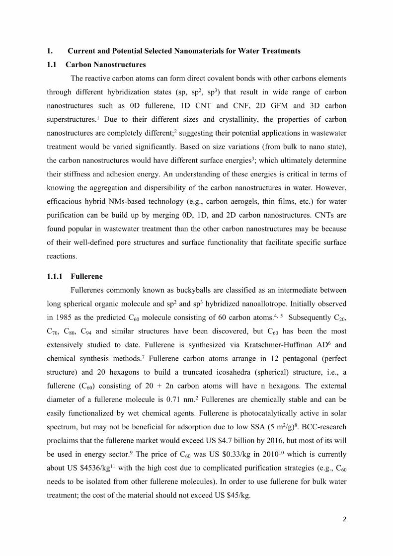
100. CNF graphene layer geometry can be categorized into platelet, herringbone/fishbone and
ribbon, or tubular perpendicular alignment, tilted and parallel to the fiber axis, respectively
(Fig. S1 (a, b and c)). Alternative CNF family members are stacked-cup/cone-stacked and
cone-helix consisting of truncated cones with helix architectures resulting large hollow cores
(Fig. S1 (d)).25
Fig. S1. Examples of CNF: (a) platelet, (b) ribbon and (c) herringbone. Structural difference
between the (d) CNF and (e) CNT. Panels a, b and c reprinted with permission from ref.2
Copyright 2014 American Chemical Society; and panels d and e reprinted with permission
from ref.28 Copyright 2005 American Institute of Physics.
CNF cone-helix lack of hollow core which is viewed as a main difference from CNT. If α = 0,
a continuous CNT structure will be restored (Fig. S1 (e)). CNF with cone and tilted-graphene

5
sheet motifs can be characterized when α > 0. Thence the angle determines the
physicochemical properties of CNF. In general, CNF has almost similar physicochemical
properties such as high mechanical, electrical, and thermal properties to CNT. CNF has been
studied in detail as an adsorbent for water pollutants, it uses for catalysis, separation, and
advanced redox has yet to be widely studied. Pyrograf Products Inc. reports nearly 70,000
pounds of CNF have been produced in recent years with the market price ranging from US
$200 to 1000/kg.29
1.1.4 Graphene Family Members
Pristine graphene (PG) is single atom thick sp2 hybridized carbon in a 2D honeycomb
lattice and is the fundamental building block of graphite. Boehm et al.30 first experimentally
identified PG in 1962, and a complete characterization was eventually completed by
Novoselov et al.31 in 2004. PG is synthesized by exfoliation of graphite in presence of specific
organic solvents under ultrasonications.32 Based on the number of layers presence, PG
classifies as single, a few- (2-5), multi- (2-10) graphene monolayer. Graphene layers >10, but
<100 nm in thickness or lateral dimensions constitute a graphite nanoplate/sheet. Two
alternative GFM are graphene oxide (GO) and reduced GO (rGO) synthesized by the
oxidative exfoliation of graphite33-36 and reduction of the GO, respectively.36-38 Graphene
quantum dot (GQD) is a recently identified GFM.39 GFM have physicochemical properties,
e.g., (Young’s modulus: 1 TPa, intrinsic strength: 130 GPa, electronic mobility: 2.5×105 cm2
V−1s−1 and thermal conductivity: >3000 WmK−1).40 GFMs have been examined as adsorbents,
photo- and biocatalysts supports, membranes, antimicrobial materials and sensors. Several
market research services suggest future GFM market prices of US $126 million (Lux
research), US $1 billion (Graphenea), and US $390 (IDTechEx’s) by 2020, 2022, and 2024,
respectively.41 Current GFM prices range from US $2.50 to 1000/g. About 1 mg of organic
pollutants removal from aqueous solution will cost US $1.77 and US $5.23 using GO and
rGO, respectively;24 suggesting a high expensive option than the CNT and CNF.
1.2 Metal and Metal Oxide Nanoparticles
Noble metal42 and metal oxide43-45 NPs have large surface area, but much lesser than
the carbon nanostructures; and can be easily functionalized with chemical groups to increase
affinity for target pollutants to be removed. In the bulk state, most of the metal particles have
shown low reactivity. Decreasing the metals size at nanoscale helps to expose more surface
reactive atoms and the functional groups which have been located at distal places will come-
up closer for enhanced chemical reactivity. But because of their high reactivity, the NP

6
undergoes self-oxidation processes and become extremely unstable. Therefore, they have
been widely studied as a component of nanocomposites rather than isolated counterpart.
1.2.1 Nanoscale Zero-Valent Iron
Nanoscale zero-valent iron (nZVI) can be synthesized using top down methods (e.g.,
abrasion, grinding, milling, and lithography) and bottom up approaches (e.g., chemical
reduction, ultrasound, and electrochemistry).46 It has zero valent metallic iron core surrounded
by iron oxide surface layer. Most of the synthesized nZVI has diameter in the range of 10-100
nm, which can be controlled via synthesis method selected. nZVI is widely used as a building
block permeable reactive barriers for in-situ ground water remediation, particularly;
perchlorates, arsenic (As) and chlorinated hydrocarbons.47 NANOFER 25S is a commercial
nZVI-based technology, which shows a high reactivity with a large scale of pollutants and
very low degree of agglomeration. Worldwide >50 nZVI pilot projects48 have been
implemented suggesting that nZVI is effective for environmental clean-up (adsorption,
degradation, and precipitation) because of its reactivity, abundance, and low cost (US
$3.75/kg ARS Technologies Inc., New Jersey, USA). It costs only US $0.00077/mg of As
removal from water.
1.2.2 Nano Silver
Pristine Ag NP is a crystalline form of metal Ag (0) particle having at least one
dimension in between 1 and 100 nm. They are obtained by wet chemistry, ion implantation
and biogenic processes.49 Ag NP produced with a number of morphologies such as spherical,
rod, prismatic, and cubic with the size and shape controlling reactivity. For example,
decreasing Ag NP size increases antibacterial activity50 because of greater SSA and Ag
toxicity as function of Ag+ dissolution. Ag NP are high thermal and electrical conductive, and
surface enhanced Raman scattering (SERS) making them versatile for application field.49 Ag
can be used as either individual NP for water disinfection or it has potential to work as a
component of other nanocomposites used for adsorption, catalysis, separation, and sensors.
The commercial price of Ag NP is US $ <10/g, and a cartridge having 120 g of Ag NP-based
antimicrobial composite can provide 3700 L of drinking water for a 5 member family. An
expense for this has been calculated only US $2 for media replacement, sediment pre-filter,
plastic assembly, and cartridge packing.24 It has been used in household water filter for a
longer period of time.51
7
1.2.3 Nano Titanium Dioxide
Titanium dioxide (TiO2) is a well-known transition metal oxide semiconductor.
Nanoscale TiO2 can be provided in a number of morphologies such as NP, nanotubes, and
nanorods. Based on their synthetic method (e.g., sol-gel, hydrothermal, solvothermal etc.) and
conditions, one can scrutinize size-dependent properties such as surface reactivity,
mechanical, optical, and electrical characteristics that are a function of surface and bulk
crystallinity. TiO2 NP exists as three major polymorphs e.g., rutile, anatase, and brookite, that
all have octahedral coordination. Rutile is more thermodynamically stable than anatase and
brookite. Anatase is photo-active in the solar spectrum, and thus has been studied widely for
water treatment. TiO2 abundance and stability promote industrial use, e.g., paints, papers,
pigments, antimicrobial coatings, and environmental application.52 The US alone (Altair and
DuPont)53 produced 1.5 Mt bulk TiO2. Realizing this market demand, only the US produces 1
Mt bulk TiO2 in 2016 where nearly 10% being TiO2 NP and within 10 years >90% is
projected to be nano. Current price of TiO2 NP ranges from 0.03 to 1.21 USD, and the
treatment cost is between US $0.50 and 1.0/g of water pollutants removal using engineered
TiO2.24 Graver Technologies and DOW international companies commercialized MetSorb and
ADSORBSIA™, respectively which utilize TiO2 NP as convenient and cost effective options
for removing As from drinking water. In addition, some commercial TiO2 photocatalysts e.g.,
Nippon Aerosil P-25,54 Kronos,55 Tayca TKP101, TKP102, and Evonik P25 are available in
the market. Since photocatalysts are not degraded in the production of oxidizing radicals, their
recrudescence and reusability would be a possible chance for their wide applications in water
treatment.
1.2.4 Nano Iron Oxide
Iron oxide NP is produced in the forms of magnetite (Fe3O4) and its oxidized form
maghemite (γ-Fe2O3) and both forms are magnetic. They can be synthesized by co-
precipitation, thermal decomposition, microemulsion, and flame pyrolysis.56 Ferrite displays
superparamagnetic behavior when their sizes <128 nm,56 and shows magnetic behavior
(saturation, Ms: 90 emu/g)57 when an external magnetic field is applied. Iron oxide NPs have
been widely used as supports for other NPs and polymers to magnetically recover adsorbents
and catalysts in both lab and field experiments. The price of Fe3O4 NP was US $0.44/g in
2010, and is currently significantly reduced at bulk levels.10 ArsenXnp (SolmeteX Inc.,
Philadelphia, PA, USA)58 is a commercially available magnetic NPs based adsorbent for As
removal and can be easily regenerated. In summary, a magnetic NP has all essential properties
which should be present to be an ideal NP for wastewater treatment. For example, it has

8
surface at which contaminants attached, a shell that provides stability and protects from
oxidation and a core that facilitates their recovery.
1.2.5 Nano Silicon Dioxide
Silicon dioxide (SiO2) is naturally abundant and convenient NP (5-25 nm) for water
treatment. SiO2 is produced by sol-gel process, reverse microemulsion, and flame synthesis.59
SiO2 NP having diameter (<5 nm) will have greatly increased surface silanol groups (≡Si-
OH),60 which can be used to graft of foreign organofunctional groups or anchor metal ions to
the surface (≡Si-OH) groups. The low production cost, high accessibility, non-toxicity, and
environmental safety have resulted in SiO2 NP being used in a number of water treatment
sectors such as adsorptions, catalysis and membranes. SiO2 NP market was US $1.62 billion
in 2014 due to its usage in a variety of commercial products.61 The cost of SiO2 NP for water
treatment is difficult to estimate, since SiO2 NP are commonly used as composite materials. In
summary, because of its diverse availability and specificity, SiO2 NP can be implemented in
continious manner and target specific pollutant removal, respectively.
1.2.6 Nano Zinc Oxide
Nanoscale zinc oxide (ZnO) have typical diameters of 20-45 nm and can be produced
in a range of morphologies e.g., nanoflowers, nanorods, nanowires, tetrapods, NPs, and
spheres, by a number of methods such as hydrothermal, sol-gel, CVD, laser ablation,
ultrasound, and anodization.62 ZnO has a tetrahedral crystal structure with a hexagonal unit
cell appears as noncentro-symmetric structure.63 ZnO NPs are transparent and have a high
electron mobility, and ambient luminescence. Water purification have evaluated the use of
ZnO NPs as adsorbent, photocatalyst, and disinfectant. Current global market demand of ZnO
NP is 30,000 t/year.64 US-Research International Inc. determines an average cost of pure ZnO
NP (80-200 nm) is US $0.46/g which can be used as a less expensive alternative to Ag NP for
water disinfection, if the efficiency of both are same in actions. Therefore, if highly reactive
ZnO NP able to be used at appropriate environment espicially antimicrobial and
photocatalysis will become one of the most promising wastewater treatment technologies due
to its flexible and manifold implementation and easy scalability.
1.2.7 Nano Aluminum Oxide
Aluminum oxide (Al2O3) NP typically consists of α, γ, δ, and θ phases among which α
is thermodynamically stable and can be synthesized by sol-gel, hydrothermal, ball milling,
pyrolysis, and laser ablation.65 Al2O3 NP has been widely used because of its enhanced

9
properties, e.g., high stability and hardness, electrically insulating and transparent. Al2O3 NP
is popular in the fields of adsorption, catalysis, antimicrobial as well as additive to ceramic
and polymer membranes. Current commercial price of Al2O3 NP (<50 nm) is US $3.7/g,
which is relatively expensive as compared to other NPs (e.g., nZVI, TiO2) for water treatment.
Nevertheless, α-Al2O3 has been commercially used as a component of ceramic composite
membrane. NanoCeram® (Argonide Corporation, Sanford, FL, USA) is a filter media
fabricated using Al2O3 nanofibers and cellulose and effective adsorptions of organic dirt,
bacteria, viruses, and proteins. To conclude, compared with many NPs, Al2O3 would be a first
priority NP for scientists for developing wastewater treatment technology especially catalysis
and membrane where stability is a major concern.
1.2.8 Nano Ceramic
Ceramic NPs are composed of inorganics such as hydroxyapatite, zirconia (ZrO2) and
others66 that are sythesized by sol-gel, sintering, and laser ablation. Bulk cerramic is brittle
and break upon impact, whereas cermaic NP is a very light, strong, flexible, durable, extremly
heat, and chemically stable.67 Ceramic NPs have been widely studied for membrane
separation, however, ceramic membranes cost 5-10 times higher than classical polymer
membranes,68 which may be offset by incraesed recyclability of the highly stable ceramic
membrane. Commercial ceramic membranes are CeraMem® and Membralox® which have
been used as point-of-use (POU) devices for water purification. Therefore, ceramic based
wastewater treatment technology would have high separation characteristics and long working
life even in harsh wastewater effluents.
1.2.9 Nano Zeolite
Zeolites are naturally abundant aluminosilicate minerals with nanometer scale (0.3-1
nm) 3D open crystalline structures. The channels and cavities of zeolite crystals are made by
tetrahedrally coordinated oxy-anions such as SiO4 and/or AlO4. The overall zeolite charge
depends on the extent of 3+/5+ doping. Pure SiO2 without any defects is neutral, whereas
negative charges appear by replacement of some Si4+ atoms by Al3+. Although zeolite can
adsorb heavy metal pollutants, zeolite based ceramic membrane has caught considerable
attention for water desalination. Estimated global zeolite consumption is 2 Tg/year driving
synthetic zeolites production (e.g., zeolite-A produced by Linde Corporation).69 Mitsui
Engineering & Shipbuilding commercializes NaA type zeolite membrane70 for fractionation
of azeotropes (e.g., isopropanol/water, acetonitrile/water and methylethylketone/water) cannot
be completely separated by distillation. Therefore, dosing of zeolite into wastewater treatment
10
technology can substantially improve characteristics and quality of treated water by saving on
energy and chemical agents.
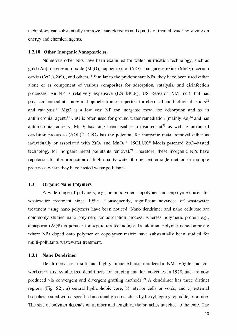
1.2.10 Other Inorganic Nanoparticles
Numerous other NPs have been examined for water purification technology, such as
gold (Au), magnesium oxide (MgO), copper oxide (CuO), manganese oxide (MnO2), cerium
oxide (CeO2), ZrO2, and others.71 Similar to the predominant NPs, they have been used either
alone or as component of various composites for adsorption, catalysis, and disinfection
processes. Au NP is relatively expensive (US $400/g, US Research NM Inc.), but has
physicochemical attributes and optoelectronic properties for chemical and biological senors72
and catalysis.73 MgO is a low cost NP for inorganic metal ion adsorption and as an
antimicrobial agent.71 CuO is often used for ground water remediation (mainly As)74 and has
antimicrobial activity. MnO2 has long been used as a disinfectant75 as well as advanced
oxidation processes (AOP)76. CeO2 has the potential for inorganic metal removal either as
individually or associated with ZrO2 and MnO2.71 ISOLUX® Media patented ZrO2-basted
technology for inorganic metal pollutants removal.77 Therefore, these inorganic NPs have
reputation for the production of high quality water through either sigle method or multiple
processes where they have hosted water pollutants.
1.3 Organic Nano Polymers
A wide range of polymers, e.g., homopolymer, copolymer and terpolymers used for
wastewater treatment since 1950s. Consequently, significant advances of wastewater
treatment using nano polymers have been noticed. Nano dendrimer and nano cellulose are
commonly studied nano polymers for adsorption process, whereas polymeric protein e.g.,
aquaporin (AQP) is popular for separation technology. In addition, polymer nanocomposite
where NPs doped onto polymer or copolymer matrix have substantially been studied for
multi-pollutants wastewater treatment.
1.3.1 Nano Dendrimer
Dendrimers are a soft and highly branched macromolecular NM. Vögtle and co-
workers78 first synthesized dendrimers for trapping smaller molecules in 1978, and are now
produced via convergent and divergent grafting methods.79 A dendrimer has three distinct
regions (Fig. S2): a) central hydrophobic core, b) interior cells or voids, and c) external
branches coated with a specific functional group such as hydroxyl, epoxy, epoxide, or amine.
The size of polymer depends on number and length of the branches attached to the core. The

11
branching units are anchored in a layer-by-layer (LBL) fashion called ‘generation’ (G). By
controlling the assembly process, one can tune dendrimer size, rigidity, hydrophobicity, and
hydrophilicity, void, volume and with stimuli response change in solvent polarity, pH, and
temperature.80 Dendrimers are mostly used for specific pollutant adsorption where the
functional group is targeted toward a specific pollutant. The company Starpharma marketed
poly (esteramine), poly-amidoamine (PAMAM), polypropyleneimine and poly-L-lysine as
Priostar®, Starburst®, Astramol® and Polylysine, respectively for both lab experimental and
field applications.81-84 In summary, dendrimers can be engineered with optimized potency that
might bring a new platform for controlled water pollutants removal.
Fig. S2. General structure showing components of a dendrimer. Reprinted with permission
from ref.85 Copyright 2015 Molecular Diversity Preservation International.
1.3.2 Nano cellulose
Nano cellulose is produced in several forms such as cellulose nanocrystals,
nanofibrillated cellulose (NFC), and bacterial nano cellulose with all having a fiber
morphology that is several µm long and have a diameter between 1 and 100 nm. Nano
cellulose is produced by acid and enzymatic catalysis, mechanical hydrolysis, and 2,2,6,6-
tetramethylpiperidinyl-1-oxyl (TEMPO)-mediated oxidation.86 The conversion of cellulose to
nano cellulose is important because of increasing SSA and generation of chemically reactive
sites or functionalities. Nano cellulose has good mechanical strength (Young's modulus in the
range 100–130 GPa)87 and controlled water solubility. Nano cellulose is a novel biomaterial
for water purification, but its utilization in others e.g., papers, cosmetics and medical products
(market value of US $47 million in 2014 and projected to approach US $278 million in
2019);88 reflecting its possibility for commercial water treatment technology.

12
1.3.3 Biopolymer
Aquaporins (AQPs) are a group of cell membrane spanning proteins that specifically
and actively transport water molecules across the cell membrane. The name “aquaporin” was
given by Agre et al.89 who were awarded Nobel Prize in 1993 for discovering the class of
proteins. AQP1 was the first discovered and now AQPs 0-12 have been identified in human
and mammalian cells.90 Microbes such as e.g., bacteria, yeast and archaea as well as plants
have also been reported to contain AQPs although different than mammalian. A single AQP is
roughly 120 kDa and consists of homotetramer structure. AQP have been utilized as a pore
channel for desalination membranes. Aquaporin A/S (Copenhagen, Denmark) is the first
commercial company who launched Aquaporin Inside™ membrane. In addition, very
recently, more than 25 patents have been filed on AQPs-based membrane systems.91
2. Asdorption
Fig. S3. Schematic representation of the adsorption forces.
Fig. S4. Structural representation of
13
four predicted major adsorption sites of CNTs in a bundle. Close-ended CNTs: adsorption
takes place PG > ES > IC, whereas open-ended CNTs: adsorption proceeds IS of open-ended
CNT walls > forms 1D chains in the PG > filling of the remaining axial sites of IC >
completion of a quasi-hexagonal monolayer on the ES.
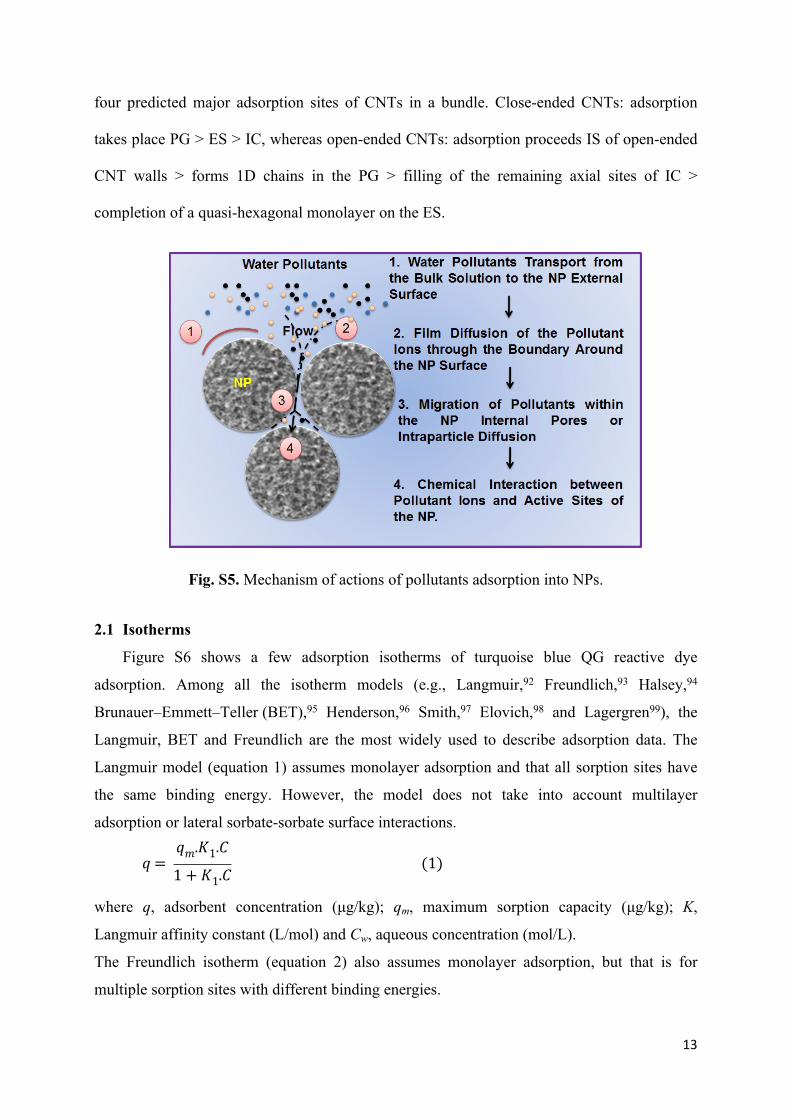
Fig. S5. Mechanism of actions of pollutants adsorption into NPs.
2.1 Isotherms
Figure S6 shows a few adsorption isotherms of turquoise blue QG reactive dye
adsorption. Among all the isotherm models (e.g., Langmuir,92 Freundlich,93 Halsey,94
Brunauer–Emmett–Teller (BET),95 Henderson,96 Smith,97 Elovich,98 and Lagergren99), the
Langmuir, BET and Freundlich are the most widely used to describe adsorption data. The
Langmuir model (equation 1) assumes monolayer adsorption and that all sorption sites have
the same binding energy. However, the model does not take into account multilayer
adsorption or lateral sorbate-sorbate surface interactions.
𝑞 = 𝑞𝑚.𝐾1.𝐶
1 + 𝐾1.𝐶 (1)
where q, adsorbent concentration (μg/kg); qm, maximum sorption capacity (μg/kg); K,
Langmuir affinity constant (L/mol) and Cw, aqueous concentration (mol/L).
The Freundlich isotherm (equation 2) also assumes monolayer adsorption, but that is for
multiple sorption sites with different binding energies.

14
𝑞𝑒 = 𝐾𝐹𝐶𝑒1/𝑛 (2)
where qe, the amount of adsorbate adsorbed per gram of the adsorbent at equilibrium (mg/g);
KF, Freundlich isotherm constant (mg/g) related to adsorption capacity; Ce, the equilibrium
concentration of adsorbate (mg/L); n, Freundlich exponent (unit less) related to adsorption
intensity.
1/n values indicate the isotherm would be (1/n = 0), favorable (0 <1/n < 1), or unfavorable
(1/n>1). For instance, the value of 1/n <1.0 for As(III) and As(V) adsorption on MWCNT-
ZrO2 adsorbent surface indicates a favorable adsorption process.100 However, Freundlich
isotherm is imperical thus physically meaningless giving minimal mechanistic insight. To
determine the kinetics of the mass transfer and chemical reaction that control the rate of the
sorption process, the pseudo-first and second order kinetic models as described in equations 3
and 4, respectively,101 yield insight.
𝑞𝑡 = 𝑞𝑒(1 ‒1
𝑒𝑘
1𝑡) (3)
𝑞𝑡 = 𝑡
1
𝑘2𝑞2𝑒
+ 𝑡
𝑞𝑒
(4)
where qt, the adsorbate mass adsorbed by a certain adsorbent mass at time t (mg/g); qe, the
equilibrium adsorption amount (mg/g); k1, the pseudo-first-order rate constant (1/min) and k2, the pseudo-second-order rate constant (g/mg min-1).

15
Fig. S6. Schematic representation of a typical batch adsorption of isotherm models. Reprinted
with permission from ref.102 Copyright 2010 SciElo. the Langmuir, Freundlich, Radke-
Prausnitz, and Redlich-Peterson isotherm models were fit to the equilibrium data on turquoise
blue QG reactive dye adsorption. Among them the Radke-Prausnitz model best represented
the equilibrium data for the dye, with coefficients of determination in the range of 0.93 to
0.99102.
2.2 Reusability of Adsorbents
Rao et al.103 designed a magnetic MIP using Fe3O4 grafted MWCNT, 4-tert-octylphenol, 4-
vinyl pyridine, and tetra-ethylorthosilicate as magnetic support, dummy template, functional
monomer, and cross-linker, respectively (Fig. S7 (Aa)). The magnetic dummy MIP (mag-
DMIPs) was highly selective to 4-nonylphenol, and the MAC was 52.4 mg/g after 20 min
contact time. Although the Ms decreases from 40.69 (MWCNT-Fe3O4) to 26.52 emu/g (mag-
DMIP) because of imprinting polymer, it is still sufficient to separate the adsorbent from
solution within 1 min as shown in Fig. S7 (Ab). In order to reusable the mag-DMIP, several
washing agents, such as methanol/water, chloroform/water, and acetonitrile/water were
evaluated with the methanol/water recovering most of the 4-nonylphenol sorbed to the mag-
DMIPs. Electrostatic self-assembly can be used to bind positively charged calcium carbonate
(CaCO3) to negatively charged CNT, forming a core-shell structure (Fig. S7 (B)). Increasing
adsorption capacity towards 2-naphthol 222 (mg/kg) (Freundlich) and enabling reusability
(>90% after four-cycle uses). Assaying an aromatic sorption capacity indicates affinity
follows the order of 2-naphthol > naphthalene > 4-chlorophenol.104 Greater affinity of 2-
naphthol is because of its greater hydrophobicity and larger aromatic ring than 4-chlorophenol
to the CNT surfaces on the composites. The classical batch sorption experiments, sorbents
such as CNT are used as a suspension in a fluiding bed making it difficult to retain the
sorbent. One solution is to immobilize the CNT on the membrane or filter to prevent release
to the environment. For example, a granular CNT-Al2O3 composite105 is porous and
mechanically stable, thus could be used in a practical column sorption application. Wei et
al.106 prepared a granular CNT/Al2O3 adsorbent using a hydrothermal calcination process and
evaluated potential for removal of pharmaceutical wastewater pollutants such as diclofenac
sodium (DS) and carbamazepine (CBZ) as displayed in Fig. S7 (C). Granular CNT/Al2O3 had
similar adsorption capacity to powder CNT attributed to minimal interference from Al2O3,
e.g., a CNT/Al2O3 reduced CNT agglomeration increasing the SSA from CNT (76) to
CNT/Al2O3 (237 m2/g) resulting in a Langmuir CNT/Al2O3 MAC of DS (40) and CBZ (60
16
μmol/L). In order to regenerate the CNT/Al2O3, thermal treatment (400oC) was applied to
combust the adsorbed DS and CBZ with removal efficiencies of regenerated CNT/Al2O3
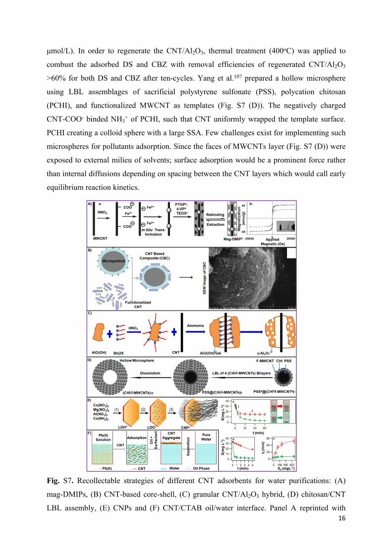
>60% for both DS and CBZ after ten-cycles. Yang et al.107 prepared a hollow microsphere
using LBL assemblages of sacrificial polystyrene sulfonate (PSS), polycation chitosan
(PCHI), and functionalized MWCNT as templates (Fig. S7 (D)). The negatively charged
CNT-COO- binded NH3+ of PCHI, such that CNT uniformly wrapped the template surface.
PCHI creating a colloid sphere with a large SSA. Few challenges exist for implementing such
microspheres for pollutants adsorption. Since the faces of MWCNTs layer (Fig. S7 (D)) were
exposed to external milieu of solvents; surface adsorption would be a prominent force rather
than internal diffusions depending on spacing between the CNT layers which would call early
equilibrium reaction kinetics.
Fig. S7. Recollectable strategies of different CNT adsorbents for water purifications: (A)
mag-DMIPs, (B) CNT-based core-shell, (C) granular CNT/Al2O3 hybrid, (D) chitosan/CNT
LBL assembly, (E) CNPs and (F) CNT/CTAB oil/water interface. Panel A reprinted with

17
permission from ref103 Copyright 2014 Elsevier. Panel B reprinted with permission from
ref.104 American Chemical Society 2015. Panel C reprinted with permission from ref.106
Copyright 2013 Elsevier. Panel D reprinted with permission from ref.107 Copyright 2012
American Chemical Society. Panel E reprinted with permission from ref.108 Copyright 2012
American Chemical Society. Panel F reprinted with permission from ref.109 Copyright 2015
Elsevier. Herein a4-tert-octylphenol, b4-vinyl pyridine, ctetra- ethylorthosilicate, dmagnetic
dummy molecularly imprinted polymers, epolystyrene sulfonate, fchitosan, gfunctionalized
MWCNT, hlayered double hydroxide, ilayered double oxide, jcarbon nanotube ponytails.
Recently, Wang et al.110 prepared a highly reusable CNT ponytail (CNP) by a 3-step
process (Fig. S7 (E)). First, Al, Mg, and Co ions were co-precipitated with OH- and CO32-
ions to form a layered double hydroxide (LDH) disc. Second, dehydration and decarbonation
of LDH was performed to form layered double oxide (LDO) and CoO. At last, CoO was
reduced to Co by H2, and CVD was used to grow CNT the nanometer-thin mineral discs.
Diameter, pore sizes and SSA of synthesized CNT were 4-7, 2-100 nm, and 365±10 m2/g,
respectively. The length of CNP was 100 μM and achieved maximum CNT mass and volume
fractions. The CNP MB adsorption capacity 150±9 mg/g, (Langmuir) and Escherichia coli (E.
coli) was 2.3±0.2 × 10⁹ CFU/g (Langmuir). CNP were separated from solution using three
methods: a) sedimentation, b) external magnet, and c) membrane filtration. Sedimentation is
very common in both large and small-scale. According to Fig. S7 (Ea), CNP (35 mg/L) settles
from the solution and becomes clear within 60 min (colored in green) as compared with free
CNT (colored in red). The precipitation followed the following sedimentation model equation
5:
𝑋 = 𝑋0𝑒‒ (𝑣
ℎ)𝑡 (5)
where X, changes of carbon concentration on time; v, the terminal settling velocity and h, the
height of the suspension 1.2±0.1 cm.
As shown in Fig. S7 E(a), critical time shift from I to II is displayed by quantitative analyses
of changes of X. In regime I, both the CNP and CNT precipitate similarly where X > 15 mg/L,
whereas decreasing X is noticed in regime II because of faster CNP precipitation than the free
CNT. CNP can also be separated by applying an external magnetic field due to the presence
of CoO NP in LDO with an Ms of 1.8 emu/g, which is sufficient to separate >95% of the CNP
in <5 min (square) faster than sedimentation (circles) (Fig. S7 (Eb)). Finally, vacuum

18
filtration of 50 mL solution of CNP through 0.8 μm membrane (green) requires less time as
compared with CNT (red) (Fig. S7 (Ec)). These results suggest that CNP would be energy and
cost efficient adsorbent than the CNT alone. However, since CNP contains highly toxic Co
may not be acceptable for water treatment.
Another separation process is to partition CNT at an oil/water (o/w) interface after
adsorption as shown in Fig. S7 (F). Cetyltrimethylammonium bromide (CTAB) is used as a
CNT surfactant such that the CNT composite coagulates at the (o/w) interface.109 The
composite has a Pb(II) MAC of 259 mg/g at pH 10.5. After adsorption, immiscible
cyclohexane added to generate 2 phases attracting all the aqueous phase CNT-Pb(II) through
shaking followed by settling. The CNT aggregation allows for easy and recycling.
Fig. S8 displays some most attractive Fe3O4-based reusable nanocomposites that have
recently been used for water purification. First, Wang et al.111 used sol-gel process to coat β-
CD on Fe3O4 which adsorbed the polychlorinated biphenyls (PCBs)-28 and 52 (Fig. S8 (a)).
The hydrophilic surface and hydrophobic cavity of β-CD were responsible to trap the water
pollutants with specific sizes.112 Fe3O4@β-CD showed higher adsorption capacity of PCB-28
(40.01 mmol/kg) than the PCB-52 (30.32 mmol/kg). Low adsorption of PCB-52 was because
of the presence of Cl atoms in phenyl rings which created different steric hindrance effects
during adsorption. Although Ms was decreased from 62.13 (Fe3O4) to 37.57 emu/g
(Fe3O4@β-CD), it was sufficient to recollect the nanocomposite within 30 sec. Second, in
order to adsorb the malachite green, RhB, Hg(II), and Ag(I); polyhedral oligomeric
silsesquioxane (POSS) bound with a dithiol organic chain on Fe3O4 (Fe3O4@POSS-SH) has
been studied (Fig. S8 (b)).113 Fe3O4@POSS-SH has shown SSA of 224.20 m2/g that helps to
adsorb 100 and 96% of malachite green and RhB, respectively. On the other hand, the thiol
group (-SH) and the POSS sulfur and oxygen atoms have contributed in adsorption of Hg(II)
(98.5) and Ag(I) (99.5%) into Fe3O4@POSS-SH. The recovered Fe3O4@POSS-SH (Ms:
14.29 emu/g) could retain at least 92% of adsorption efficiency after 5-cycle uses, suggesting
a good reusability of the nanocomposite. Third, poly(m-phenylenediamine) (PmPD) has been
used to coat Fe3O4 (Fe3O4@PmPD), which increases the Redlich−Peterson MAC of Cr(VI)
from 46.79 (Fe3O4) to 246.09 mg/g (Fe3O4@PmPD) (Fig. S8 (c)).114 The Cr(VI) removal
efficiency of Fe3O4@PmPD has found higher than the HA coated Fe3O4.115 Although the
adsorption, and reduction of Cr(VI) to Cr(III) have occurred simultaneously in both studies,
any chances of increasing the Cr adsorption capacity might be due to the nature and functional
groups of polymer used. Washing agent, e.g., NaOH is used to clean Fe3O4@PmPD after

19
adsorption and could be recollectable (Ms: 73 emu/g) which retained 70% of the Cr
adsorption capacity after 6-cycle uses.
Fig. S8. Fabrications of Fe3O4-based reusable nanocomposites and their adsorptive
mechanisms: (a) Fe3O4@β-CD, (b) Fe3O4-POSS-SH, (c) Fe3O4@PmPD, and (d) Fe3O4-
EDTA. Panel (a) reprinted with permission from ref.111 Copyright 2015 Elsevier. Panel (b)
reprinted with permission from ref.113 Copyright 2013 American Chemical Society. Panel (c)
reprinted with permission from ref.114 Copyright 2015 American Chemical Society. Panel (d)
reprinted with permission from ref.116 Copyright 2015 Elsevier Here aβ-cyclodextrin, bpolychlorinated biphenyls, cpolyhedral oligomeric silsesquioxane, dm-phenylenediamine, e3-
aminopropyltriethoxysilane and fethylenediaminetetraacetic acid.
At last, EDTA is a popular metal chelating agent that has been used to coat Fe3O4 (Fig. S8
(d)). The Fe3O4-EDTA showed Langmuir MAC of Cd(II) 79.4 mg/g and Freundlich MAC of
Pb(II) 100 mg/g.116 The nanocomposite could be easily recollectable (Ms: 52.8 emu/g) and
nearly 80% of removal efficiency could be maintained after 5-cycle uses. The results can also
be comparable with thiosalicylhydrazide modified Fe3O4 for metal adsorptions where

20
Langmuir MAC follows the trend of 188.7 Pb(II) > 107.5 Cd(II) > 76.9 Cu(I) > 51.3 Zn(II) >
27.7 mg/g.117
2.3 Factors Controlling Adsorption
Fig. S9. Relationship between BET surface area of CNT and MAC of (a) organic and (b)
inorganic water pollutants. Data collected from refs. (a)118-130 and refs. (b).131-138
21
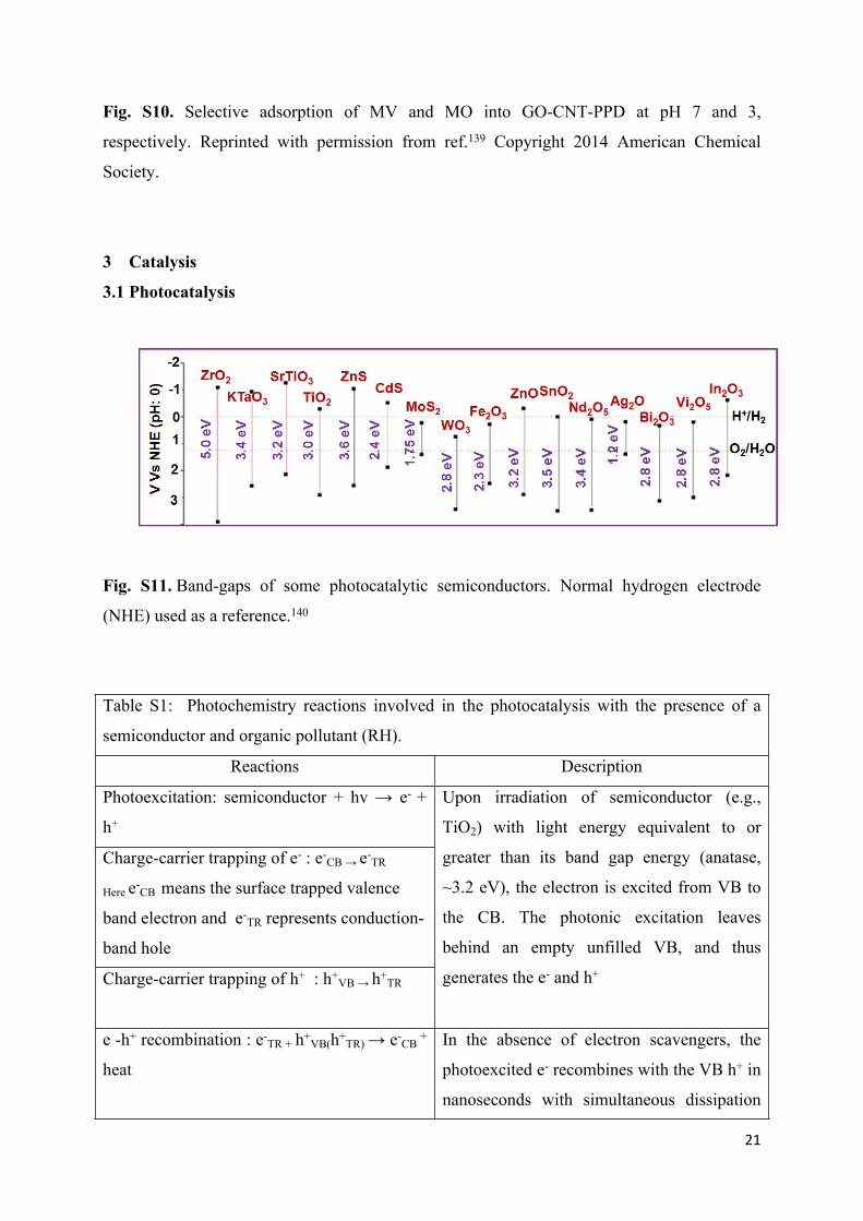
Fig. S10. Selective adsorption of MV and MO into GO-CNT-PPD at pH 7 and 3,
respectively. Reprinted with permission from ref.139 Copyright 2014 American Chemical
Society.
3 Catalysis
3.1 Photocatalysis
Fig. S11. Band-gaps of some photocatalytic semiconductors. Normal hydrogen electrode
(NHE) used as a reference.140
Table S1: Photochemistry reactions involved in the photocatalysis with the presence of a
semiconductor and organic pollutant (RH).
Reactions Description
Photoexcitation: semiconductor + hv → e- +
h+
Charge-carrier trapping of e- : e-CB → e-
TR
Here e-CB means the surface trapped valence
band electron and e-TR represents conduction-
band hole
Charge-carrier trapping of h+ : h+VB → h+
TR
Upon irradiation of semiconductor (e.g.,
TiO2) with light energy equivalent to or
greater than its band gap energy (anatase,
~3.2 eV), the electron is excited from VB to
the CB. The photonic excitation leaves
behind an empty unfilled VB, and thus
generates the e- and h+
e -h+ recombination : e-TR + h+
VB(h+TR) → e-
CB +
heat
In the absence of electron scavengers, the
photoexcited e- recombines with the VB h+ in
nanoseconds with simultaneous dissipation

22
of heat energy. Hence, the presence of e-
scavengers is vital for prolonging the
recombination and successful functioning of
photocatalysis
Oxidation of hydroxyls: (OH- )ads + h+ → oOHads
Photoexcited e- scavenging : (O2)ads + e- → O2
Generally, the h+ reacts with the adsorbed
surface OH- groups on the semiconductor
particle to produce surface adsorbed radical oOHads.
Protonation of superoxides : O2.- + oOH →
HOOo
Co-scavenging of e- : HOOo + e- → HO2-
Formation of H2O2: HOO- + H+ → H2O2
This O2o- radical can be further protonated to
form the HO2o and subsequently H2O2
Photodegradation by oOH : RH + oOH → Ro +
H2O
Direct photoholes: RH + h+ → Ro →
Intermediate(s)/Final Degradation Products
Photogenerated h+ and the formed reactive
oxygen species (e.g., oOH) can participate in
the degradation of organic pollutants
TiO2/hv
RH → intermediactes → CO2 + H2O +
inorganic ions
Organic compounds are degraded to their
corresponding intermediates and further
mineralized to CO2, H2O and inorganic ions
(from heteroatoms

23
Fig. S12. Mechanisms of the organic-ligand modified TiO2 for MB degradation under VL
irradiation.
Fig. S13. Summary of photocatalytic ozonations reaction principles. Reprinted with
permission from ref.141 Copyright 2015 Elsevier.
3.2 CWAO
24
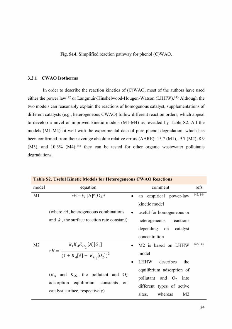
Fig. S14. Simplified reaction pathway for phenol (C)WAO.
3.2.1 CWAO Isotherms
In order to describe the reaction kinetics of (C)WAO, most of the authors have used
either the power law142 or Langmuir-Hinshelwood-Hougen-Watson (LHHW).143 Although the
two models can reasonably explain the reactions of homogenous catalyst, supplementations of
different catalysts (e.g., heterogeneous CWAO) follow different reaction orders, which appeal
to develop a novel or improved kinetic models (M1-M4) as revealed by Table S2. All the
models (M1-M4) fit-well with the experimental data of pure phenol degradation, which has
been confirmed from their average absolute relative errors (AARE): 15.7 (M1), 9.7 (M2), 8.9
(M3), and 10.3% (M4);144 they can be tested for other organic wastewater pollutants
degradations.
Table S2. Useful Kinetic Models for Heterogeneous CWAO Reactions
model equation comment refs
M1 rH = k1 [A]p [O2]q
(where rH, heterogeneous combinations
and k1, the surface reaction rate constant)
an empirical power-law
kinetic model
useful for homogeneous or
heterogeneous reactions
depending on catalyst
concentration
142, 144
M2𝑟𝐻 =
𝑘1𝐾𝐴𝐾𝑂2 [𝐴][𝑂2]
(1 + 𝐾𝐴[𝐴] + 𝐾𝑂2[𝑂2])2
(KA and KO2, the pollutant and O2
adsorption equilibrium constants on
catalyst surface, respectively)
M2 is based on LHHW
model
LHHW describes the
equilibrium adsorption of
pollutant and O2 into
different types of active
sites, whereas M2
143-145

25
represents single-site
mechanism and
irreversible reaction
between them
M3𝑟𝐻 =
𝑘1𝐾𝐴𝐾𝑂20.5[𝐴][𝑂2]0.5]
(1 + 𝐾𝐴[𝐴] + 𝐾𝑂20.5[𝑂2]0.5)2
M3 is quite similar to M2
in terms of same active
site reaction of pollutant
and O2 molecule, but O2
molecule undergoes
dissociation
surface reaction occurs
between the adsorbed
pollutant and O2
144
M4𝑟𝐻 =
𝑘1𝐾𝐴𝐾𝑂20.5[𝐴][𝑂2]0.5]
(1 + 𝐾𝐴[𝐴]) + (1 + 𝐾𝑂20.5[𝑂2]0.5)
suitable for reaction when
the dissociated O2 and
pollutant adsorb into
distinctly different active
sites of the catalyst
144, 146
However, the quality of M1-M4 has been compromised to describe the reactions of
CWAO of real wastewater pollutants. Some models have been improved using variables e.g.,
TOC and COD. Li et al.147 developed a triangular model called general lumped kinetic model
(GLKM) for non-catalytic WAO of acetic acid (Fig. S15 (a)). Since the GLKM model has
found unsuitable to express heterogeneous CWAO, Belkacemi et al.148 further improved the
performance of GLKM model based on LHHW called extended lumped kinetic model
(ELKM) (Fig. S15 (b)), which could be used to describe the reaction orders of multiple
wastewater pollutants degradation. The main difference between these two models is GLKM
could not express the adsorption/desorption of reactants/product as compared with ELKM.
26
Fig. S15. (a) Reaction orders of GLKM: Lump A, parent compounds and unstable
intermediates except acetic acid; Lump B, the refractory intermediates and acetic acid; and
Lump C, the end products; (b) Reaction orders of ELKM: Lump A, the parent aqueous
compounds adsorbed into catalyst surface; Lump B, the surface reactions of the adsorbed
intermediate; and Lump C, the end
product. Here K and its subscripts
represent the kinetic rate constant.
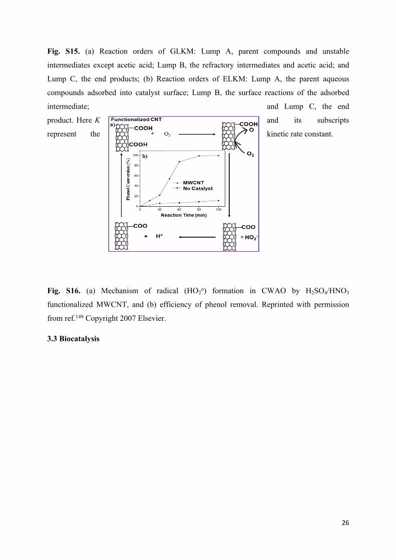
Fig. S16. (a) Mechanism of radical (HO2o) formation in CWAO by H2SO4/HNO3
functionalized MWCNT, and (b) efficiency of phenol removal. Reprinted with permission
from ref.149 Copyright 2007 Elsevier.
3.3 Biocatalysis

27
Fig. S17. Selected nanocareers for enzymes immobilization: (a) CNF/CNT favors side-by-
side attachments of two enzymes, (b) silica with nanoporous surface architectures is suitable
not only to immobilize the enzymes, but also other cofactors and/or biomolecules: i) TEM
image of dendrimer like nanoporous silica, (c) ship in a bottle (SB) model: i) to confine
enzymes inside the cage and ii) TEM image of SB topology, (d) gate keeper enzyme
immobilization for superior substrate diffusion: ii) optical micrograph of nanocages, and (e)
protein immobilized onto nanoflower: ii-iii) SEM images of Cu3(PO4)2.3H2O nanoflowers.
Panel (a) reprinted with permission from ref.150 Copyright 2014 Royal Society. Panel (b)
reprinted with permission from ref.151 Copyright 2013 Wiley-VCH. Panel (c) reprinted with
permission from ref.152 Copyright 2005 Wiley-VCH. Panel (d) reprinted with permission from
ref.153 Copyright 2013 Royal Society of Chemistry. Panel (e) reprinted with permission from
ref.154 Copyright 2012 Nature.

28
Fig. S18. Effects of (a) pH and (b) temperature on 3,4-POD activities. Reprinted with
permission from ref.155 Copyright 2016 Nature.
4 Membrane and Filtration
29
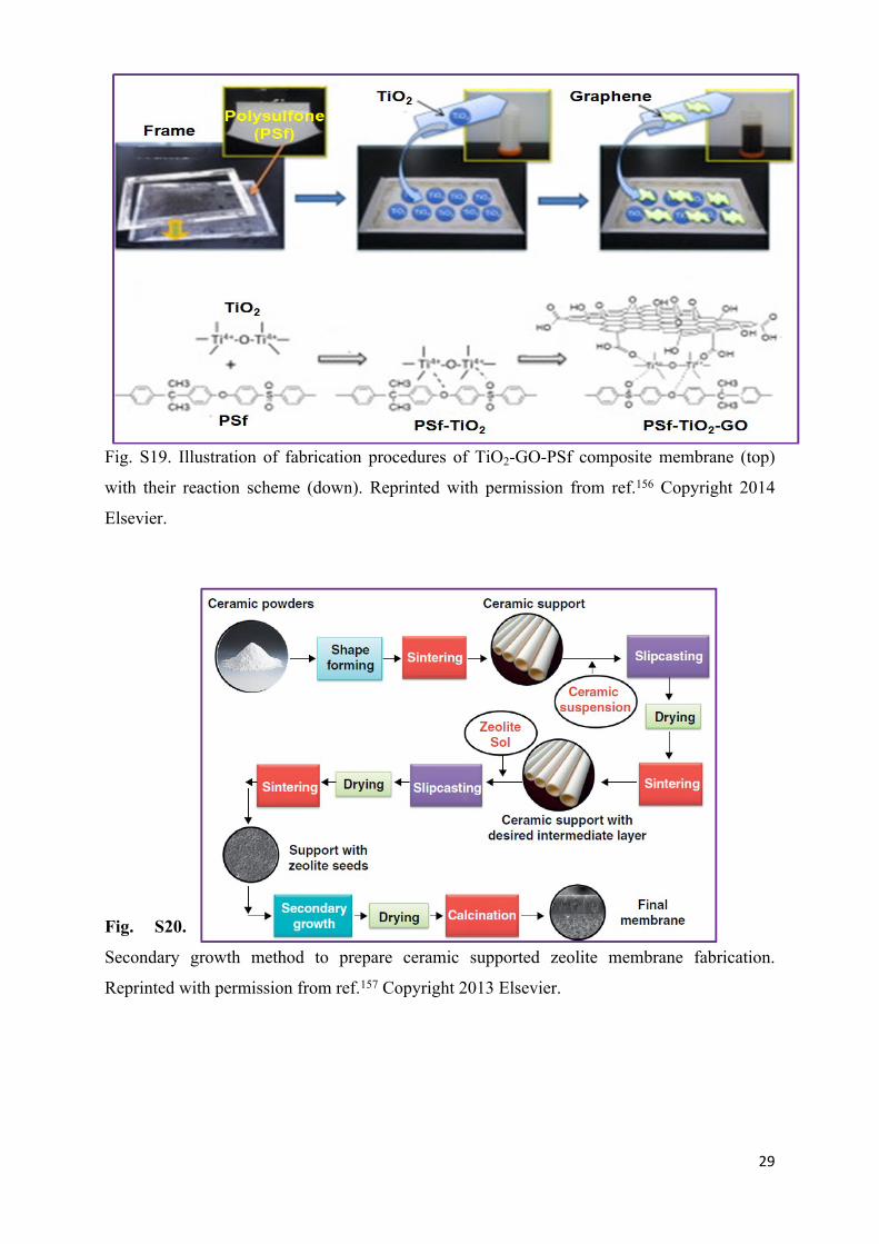
Fig. S19. Illustration of fabrication procedures of TiO2-GO-PSf composite membrane (top)
with their reaction scheme (down). Reprinted with permission from ref.156 Copyright 2014
Elsevier.
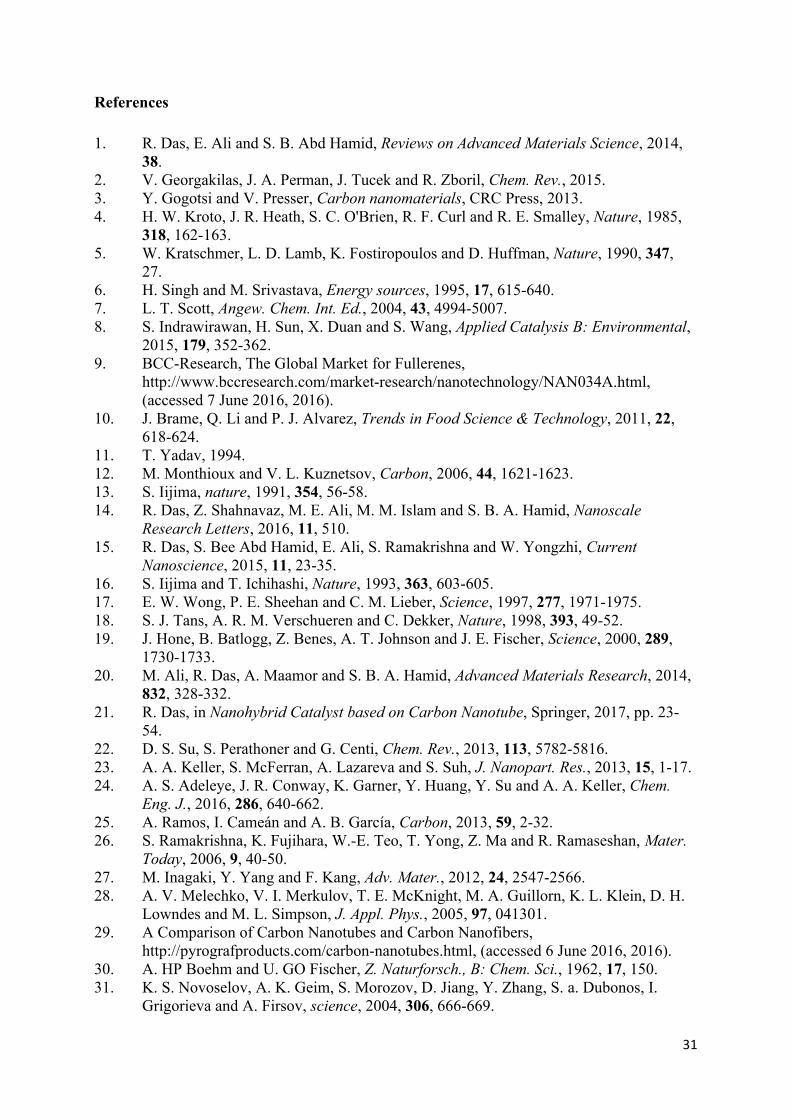
Fig. S20.
Secondary growth method to prepare ceramic supported zeolite membrane fabrication.
Reprinted with permission from ref.157 Copyright 2013 Elsevier.

30
Fig. S21. Schematic illustration of (A) block copolymer, and (B) effects of charge density on
the block copolymer phase nanostructures: (a) 2.5% charge, (b) 5.3% charge and (c) 17.0%
charge. Panel (A) reprinted with permission from ref.158 Copyright 2011 Nature. Panel (B)
reprinted with permission from ref.159 Copyright 2014 Nature.
Fig. S22. Illustration of three methods for NP coating onto ceramic membrane: (a)
electrophoretic deposition: charged TiO2 deposits onto alumina, (b) 3-
aminopropytriethoxysilane (APTES) molecule as a linker between the Ag NP and the ceramic
support, and (c) organic binder (e.g., phytic acid) for doping the Fe2O3 NP on ceramic
membrane surface using LBL apprach. Reprinted with permission from ref.160 Copyright 2010
Elsevier.
31
References
1. R. Das, E. Ali and S. B. Abd Hamid, Reviews on Advanced Materials Science, 2014, 38.
2. V. Georgakilas, J. A. Perman, J. Tucek and R. Zboril, Chem. Rev., 2015.3. Y. Gogotsi and V. Presser, Carbon nanomaterials, CRC Press, 2013.4. H. W. Kroto, J. R. Heath, S. C. O'Brien, R. F. Curl and R. E. Smalley, Nature, 1985,
318, 162-163.5. W. Kratschmer, L. D. Lamb, K. Fostiropoulos and D. Huffman, Nature, 1990, 347,
27.6. H. Singh and M. Srivastava, Energy sources, 1995, 17, 615-640.7. L. T. Scott, Angew. Chem. Int. Ed., 2004, 43, 4994-5007.8. S. Indrawirawan, H. Sun, X. Duan and S. Wang, Applied Catalysis B: Environmental,
2015, 179, 352-362.9. BCC-Research, The Global Market for Fullerenes,
http://www.bccresearch.com/market-research/nanotechnology/NAN034A.html, (accessed 7 June 2016, 2016).
10. J. Brame, Q. Li and P. J. Alvarez, Trends in Food Science & Technology, 2011, 22, 618-624.
11. T. Yadav, 1994.12. M. Monthioux and V. L. Kuznetsov, Carbon, 2006, 44, 1621-1623.13. S. Iijima, nature, 1991, 354, 56-58.14. R. Das, Z. Shahnavaz, M. E. Ali, M. M. Islam and S. B. A. Hamid, Nanoscale
Research Letters, 2016, 11, 510.15. R. Das, S. Bee Abd Hamid, E. Ali, S. Ramakrishna and W. Yongzhi, Current
Nanoscience, 2015, 11, 23-35.16. S. Iijima and T. Ichihashi, Nature, 1993, 363, 603-605.17. E. W. Wong, P. E. Sheehan and C. M. Lieber, Science, 1997, 277, 1971-1975.18. S. J. Tans, A. R. M. Verschueren and C. Dekker, Nature, 1998, 393, 49-52.19. J. Hone, B. Batlogg, Z. Benes, A. T. Johnson and J. E. Fischer, Science, 2000, 289,
1730-1733.20. M. Ali, R. Das, A. Maamor and S. B. A. Hamid, Advanced Materials Research, 2014,
832, 328-332.21. R. Das, in Nanohybrid Catalyst based on Carbon Nanotube, Springer, 2017, pp. 23-
54.22. D. S. Su, S. Perathoner and G. Centi, Chem. Rev., 2013, 113, 5782-5816.23. A. A. Keller, S. McFerran, A. Lazareva and S. Suh, J. Nanopart. Res., 2013, 15, 1-17.24. A. S. Adeleye, J. R. Conway, K. Garner, Y. Huang, Y. Su and A. A. Keller, Chem.
Eng. J., 2016, 286, 640-662.25. A. Ramos, I. Cameán and A. B. García, Carbon, 2013, 59, 2-32.26. S. Ramakrishna, K. Fujihara, W.-E. Teo, T. Yong, Z. Ma and R. Ramaseshan, Mater.
Today, 2006, 9, 40-50.27. M. Inagaki, Y. Yang and F. Kang, Adv. Mater., 2012, 24, 2547-2566.28. A. V. Melechko, V. I. Merkulov, T. E. McKnight, M. A. Guillorn, K. L. Klein, D. H.
Lowndes and M. L. Simpson, J. Appl. Phys., 2005, 97, 041301.29. A Comparison of Carbon Nanotubes and Carbon Nanofibers,
http://pyrografproducts.com/carbon-nanotubes.html, (accessed 6 June 2016, 2016).30. A. HP Boehm and U. GO Fischer, Z. Naturforsch., B: Chem. Sci., 1962, 17, 150.31. K. S. Novoselov, A. K. Geim, S. Morozov, D. Jiang, Y. Zhang, S. a. Dubonos, I.
Grigorieva and A. Firsov, science, 2004, 306, 666-669.

32
32. Y. Hernandez, V. Nicolosi, M. Lotya, F. M. Blighe, Z. Sun, S. De, I. McGovern, B. Holland, M. Byrne and Y. K. Gun'Ko, Nature nanotechnology, 2008, 3, 563-568.
33. W. S. Hummers Jr and R. E. Offeman, J. Am. Chem. Soc., 1958, 80, 1339-1339.34. L. Staudenmaier, Ber Dtsch Chem Ges, 1898, 31, 1481-1487.35. B. Brodie, Ann. Chim. Phys, 1855, 45, 351-353.36. D. R. Dreyer, S. Park, C. W. Bielawski and R. S. Ruoff, Chem. Soc. Rev., 2010, 39,
228-240.37. S. Abdolhosseinzadeh, H. Asgharzadeh and H. S. Kim, Scientific reports, 2015, 5.38. Y. Zhu, S. Murali, W. Cai, X. Li, J. W. Suk, J. R. Potts and R. S. Ruoff, Adv. Mater.,
2010, 22, 3906-3924.39. L. Ponomarenko, F. Schedin, M. Katsnelson, R. Yang, E. Hill, K. Novoselov and A.
Geim, Science, 2008, 320, 356-358.40. K. S. Novoselov, V. Fal, L. Colombo, P. Gellert, M. Schwab and K. Kim, Nature,
2012, 490, 192-200.41. P. Shapira, A. Gök and F. S. Yazdi, Graphene Research and Enterprise: Mapping
Innovation and Business Growth in a Strategic Emerging Technology, Nesta Working Paper, 2015.
42. T. Pradeep, Thin Solid Films, 2009, 517, 6441-6478.43. Q. Zhang, Q. Du, M. Hua, T. Jiao, F. Gao and B. Pan, Environ. Sci. Technol., 2013,
47, 6536-6544.44. Y. Liu, C. Luo, J. Sun, H. Li, Z. Sun and S. Yan, Journal of Materials Chemistry A,
2015, 3, 5674-5682.45. I. Ali, Chem. Rev., 2012, 112, 5073-5091.46. M. Stefaniuk, P. Oleszczuk and Y. S. Ok, Chem. Eng. J., 2016, 287, 618-632.47. L. Li, J. Hu, X. Shi, M. Fan, J. Luo and X. Wei, Environmental Science and Pollution
Research, 2016, 1-21.48. W. Yan, H.-L. Lien, B. E. Koel and W.-x. Zhang, Environmental Science: Processes
& Impacts, 2013, 15, 63-77.49. K. M. M. Abou El-Nour, A. a. Eftaiha, A. Al-Warthan and R. A. A. Ammar, Arabian
Journal of Chemistry, 2010, 3, 135-140.50. S. Agnihotri, S. Mukherji and S. Mukherji, RSC Advances, 2014, 4, 3974-3983.51. V. A. Oyanedel-Craver and J. A. Smith, Environ. Sci. Technol., 2007, 42, 927-933.52. U. EPA, National Center for Environmental Assessment, Office of Research and
Development, US Environmental Protection Agency, 2009, 222.53. D. K. Ellsworth, D. Verhulst, T. M. Spitler and B. J. Sabacky, Chemical innovation,
2000, 30, 30-35.54. X. Yan, T. Ohno, K. Nishijima, R. Abe and B. Ohtani, Chem. Phys. Lett., 2006, 429,
606-610.55. M. Pelaez, N. T. Nolan, S. C. Pillai, M. K. Seery, P. Falaras, A. G. Kontos, P. S.
Dunlop, J. W. Hamilton, J. A. Byrne and K. O'Shea, Applied Catalysis B: Environmental, 2012, 125, 331-349.
56. A. H. Lu, E. e. L. Salabas and F. Schüth, Angew. Chem. Int. Ed., 2007, 46, 1222-1244.57. V. Mameli, A. Musinu, A. Ardu, G. Ennas, D. Peddis, D. Niznansky, C. Sangregorio,
C. Innocenti, N. T. Thanh and C. Cannas, Nanoscale, 2016, 8, 10124-10137.58. I. Gehrke, A. Geiser and A. Somborn-Schulz, Nanotechnology, science and
applications, 2015, 8, 1.59. I. A. Rahman and V. Padavettan, Journal of Nanomaterials, 2012, 2012, 8.60. C. J. Brinker and G. W. Scherer, Sol-gel science: the physics and chemistry of sol-gel
processing, Academic press, 2013.61. Grand-View-Research, Precipitated Silica Market Analysis By Application (Rubber,
Agrochemicals, Oral Care, Food Industry)And Segment Forecasts To 2022,

33
http://www.grandviewresearch.com/industry-analysis/precipitated-silica-market, (accessed 10 June, 2016).
62. S. S. Kumar, P. Venkateswarlu, V. R. Rao and G. N. Rao, International Nano Letters, 2013, 3, 1-6.
63. S. Sabir, M. Arshad and S. K. Chaudhari, The Scientific World Journal, 2014, 2014.64. Research-&-Market, The Global Market for Zinc Oxide Nanoparticles 2015,
http://www.researchandmarkets.com/reports/3293016/the-global-market-for-zinc-oxide-nanoparticles, (accessed 10 June, 2016).
65. L. D. Hart, 1989.66. A.-I. Moreno-Vega, T. Gomez-Quintero, R.-E. Nunez-Anita, L.-S. Acosta-Torres and
V. Castaño, Journal of Nanotechnology, 2012, 2012.67. P. Patel, MRS Bull., 2014, 39, 929-929.68. R. Singh, Hybrid Membrane Systems for Water Purification: Technology, Systems
Design and Operations, Elsevier, 2006.69. A. Dyer, 1988.70. V. Van Hoof, C. Dotremont and A. Buekenhoudt, Sep. Purif. Technol., 2006, 48, 304-
309.71. K. Simeonidis, S. Mourdikoudis, E. Kaprara, M. Mitrakas and L. Polavarapu,
Environmental Science: Water Research & Technology, 2016, 2, 43-70.72. K. Saha, S. S. Agasti, C. Kim, X. Li and V. M. Rotello, Chem. Rev., 2012, 112, 2739-
2779.73. B. Puértolas, Á. Mayoral, R. Arenal, B. Solsona, A. Moragues, S. Murcia-Mascaros,
P. Amorós, A. B. Hungría, S. H. Taylor and T. García, ACS Catalysis, 2015, 5, 1078-1086.
74. K. J. McDonald, B. Reynolds and K. Reddy, Scientific reports, 2015, 5.75. S. M. Dizaj, F. Lotfipour, M. Barzegar-Jalali, M. H. Zarrintan and K. Adibkia,
Materials Science and Engineering: C, 2014, 44, 278-284.76. K. A. M. Ahmed, H. Peng, K. Wu and K. Huang, Chem. Eng. J., 2011, 172, 531-539.77. ISOLUX®Media, ISOLUX® Media is MEL Chemicals´ patented free-flowing
amorphous powder designed specifically for heavy metals reduction in drinking water applications, http://www.zrpure.com/drinking-water/isolux_media.asp, (accessed 11 June, 2016).
78. E. Buhleier, W. Wehner and F. Vögtle, Chemischer Informationsdienst, 1978, 9.79. D. A. Tomalia, Prog. Polym. Sci., 2005, 30, 294-324.80. G. Newkome, C. Moorefield and F. Vögtle, Dendritic Molecules: Concepts,
Syntheses, Perspectives, 1996, 37-47.81. D. R. Swanson, B. Huang, H. G. Abdelhady and D. A. Tomalia, New J. Chem., 2007,
31, 1368-1378.82. D. A. Tomalia and J. M. Fréchet, J. Polym. Sci., Part A: Polym. Chem., 2002, 40,
2719-2728.83. D. Tomalia and M. Rookmaker, Journal, 2009.84. D. Patton, Y. C. Sweeney, T. McCarthy and S. Hillier, Antimicrob. Agents
Chemother., 2006, 50, 1696-1700.85. A. Sharma and A. Kakkar, Molecules, 2015, 20, 16987-17015.86. I. A. Sacui, R. C. Nieuwendaal, D. J. Burnett, S. J. Stranick, M. Jorfi, C. Weder, E. J.
Foster, R. T. Olsson and J. W. Gilman, ACS applied materials & interfaces, 2014, 6, 6127-6138.
87. A. Dufresne, Mater. Today, 2013, 16, 220-227.88. BCC-Research, ‘Biomaterial of the Future’ Nanocellulose to Send Market Booming
with 42.8% CAGR, http://www.bccresearch.com/pressroom/avm/biomaterial-of-the-

34
future-nanocellulose-to-send-market-booming-with-42.8-percent-cagr, (accessed 11 June, 2016).
89. P. Agre, S. Sasaki and M. Chrispeels, American Journal of Physiology-Renal Physiology, 1993, 265, F461-F461.
90. C. H. Nielsen, Analytical and bioanalytical chemistry, 2009, 395, 697-718.91. C. Tang, Z. Wang, I. Petrinić, A. G. Fane and C. Hélix-Nielsen, Desalination, 2015,
368, 89-105.92. I. Langmuir, J. Am. Chem. Soc., 1918, 40, 1361-1403.93. H. Freundlich, Phys. Chem., 1906, 57, 385-470.94. G. Halsey, The Journal of Chemical Physics, 1948, 16, 931-937.95. S. Brunauer, P. H. Emmett and E. Teller, J. Am. Chem. Soc., 1938, 60, 309-319.96. A. P. Henderson, L. N. Seetohul, A. K. Dean, P. Russell, S. Pruneanu and Z. Ali,
Langmuir, 2009, 25, 931-938.97. C. Giles, T. MacEwan, S. Nakhwa and D. Smith, Journal of the Chemical Society
(Resumed), 1960, 3973-3993.98. O. G. L. SY Elovich, zv. Akad. Nauk. SSSR, Otd. Khim. Nauk 1962, 2, 209.99. S. Lagergren, Band, 1898, 24, 1-39.100. S. A. Ntim and S. Mitra, J. Colloid Interface Sci., 2012, 375, 154-159.101. H. Qiu, L. Lv, B.-c. Pan, Q.-j. Zhang, W.-m. Zhang and Q.-x. Zhang, Journal of
Zhejiang University Science A, 2009, 10, 716-724.102. D. Schimmel, K. Fagnani, J. Santos, M. Barros and E. Silva, Brazilian Journal of
Chemical Engineering, 2010, 27, 289-298.103. W. Rao, R. Cai, Y. Yin, F. Long and Z. Zhang, Talanta, 2014, 128, 170-176.104. L. Xu, J. Li and M. Zhang, Industrial & Engineering Chemistry Research, 2015, 54,
2379-2384.105. D. Shan, S. Deng, T. Zhao, G. Yu, J. Winglee and M. R. Wiesner, Chem. Eng. J.,
2016, 294, 353-361.106. H. Wei, S. Deng, Q. Huang, Y. Nie, B. Wang, J. Huang and G. Yu, Water Res., 2013,
47, 4139-4147.107. C. Yang and P. Liu, Industrial & Engineering Chemistry Research, 2012, 51, 13346-
13353.108. H. Wang, H. Ma, W. Zheng, D. An and C. Na, ACS applied materials & interfaces,
2014.109. L. Gao, H. Yin, X. Mao, H. Zhu, W. Xiao and D. Wang, Environmental Science and
Pollution Research, 2015, 1-8.110. H. Wang, H. Ma, W. Zheng, D. An and C. Na, ACS applied materials & interfaces,
2014, 6, 9426-9434.111. M. Wang, P. Liu, Y. Wang, D. Zhou, C. Ma, D. Zhang and J. Zhan, J. Colloid
Interface Sci., 2015, 447, 1-7.112. W. Hu, X. Wu, F. Jiao, W. Yang and Y. Zhou, Desalination and Water Treatment,
2016, 1-12.113. H.-B. He, B. Li, J.-P. Dong, Y.-Y. Lei, T.-L. Wang, Q.-W. Yu, Y.-Q. Feng and Y.-B.
Sun, ACS applied materials & interfaces, 2013, 5, 8058-8066.114. T. Wang, L. Zhang, C. Li, W. Yang, T. Song, C. Tang, Y. Meng, S. Dai, H. Wang and
L. Chai, Environ. Sci. Technol., 2015, 49, 5654-5662.115. W. Jiang, Q. Cai, W. Xu, M. Yang, Y. Cai, D. D. Dionysiou and K. E. O’Shea,
Environ. Sci. Technol., 2014, 48, 8078-8085.116. Y. Huang and A. A. Keller, Water Res., 2015, 80, 159-168.117. K. Zargoosh, H. Abedini, A. Abdolmaleki and M. R. Molavian, Industrial &
Engineering Chemistry Research, 2013, 52, 14944-14954.118. L. Zhang, P. Fang, L. Yang, J. Zhang and X. Wang, Langmuir, 2013, 29, 3968-3975.

35
119. X. Yan, B. Shi, J. Lu, C. Feng, D. Wang and H. Tang, J. Colloid Interface Sci., 2008, 321, 30-38.
120. H.-H. Cho, H. Huang and K. Schwab, Langmuir, 2011, 27, 12960-12967.121. S. Zhou, Y. Shao, N. Gao, J. Deng and C. Tan, CLEAN–Soil, Air, Water, 2013, 41,
539-547.122. Y. Lu, M. Jiang, C. Wang, Y. Wang and W. Yang, Water, Air, & Soil Pollution, 2013,
224, 1-12.123. N. Rambabu, C. A. Guzman, J. Soltan and V. Himabindu, Chemical Engineering &
Technology, 2012, 35, 272-280.124. G.-C. Chen, X.-Q. Shan, Y.-S. Wang, Z.-G. Pei, X.-E. Shen, B. Wen and G. Owens,
Environ. Sci. Technol., 2008, 42, 8297-8302.125. G.-C. Chen, X.-Q. Shan, Y.-Q. Zhou, X.-e. Shen, H.-L. Huang and S. U. Khan, J.
Hazard. Mater., 2009, 169, 912-918.126. Q. Fang and B. Chen, Carbon, 2012, 50, 2209-2219.127. B. Pan, D. Lin, H. Mashayekhi and B. Xing, Environ. Sci. Technol., 2008, 42, 5480-
5485.128. J. L. Sotelo, A. R. Rodríguez, M. M. Mateos, S. D. Hernández, S. A. Torrellas and J.
G. Rodríguez, Journal of Environmental Science and Health, Part B, 2012, 47, 640-652.
129. G.-C. Chen, X.-Q. Shan, Z.-G. Pei, H. Wang, L.-R. Zheng, J. Zhang and Y.-N. Xie, J. Hazard. Mater., 2011, 188, 156-163.
130. L. A. Al-Khateeb, A. Y. Obaid, N. A. Asiri and M. A. Salam, Journal of Industrial and Engineering Chemistry, 2014, 20, 916-924.
131. Y.-H. Li, S. Wang, J. Wei, X. Zhang, C. Xu, Z. Luan, D. Wu and B. Wei, Chem. Phys. Lett., 2002, 357, 263-266.
132. R. Q. Long and R. T. Yang, J. Am. Chem. Soc., 2001, 123, 2058-2059.133. Y.-H. Li, S. Wang, Z. Luan, J. Ding, C. Xu and D. Wu, Carbon, 2003, 41, 1057-1062.134. C. Lu and C. Liu, J. Chem. Technol. Biotechnol., 2006, 81, 1932-1940.135. H. Wang, A. Zhou, F. Peng, H. Yu and J. Yang, J. Colloid Interface Sci., 2007, 316,
277-283.136. H. Wang, A. Zhou, F. Peng, H. Yu and L. Chen, Materials Science and Engineering:
A, 2007, 466, 201-206.137. Y.-H. Li, Z. Di, J. Ding, D. Wu, Z. Luan and Y. Zhu, Water Res., 2005, 39, 605-609.138. C. Lu, C. Liu and G. P. Rao, J. Hazard. Mater., 2008, 151, 239-246.139. C. Sarkar, C. Bora and S. K. Dolui, Industrial & Engineering Chemistry Research,
2014, 53, 16148-16155.140. A. Kudo and Y. Miseki, Chem. Soc. Rev., 2009, 38, 253-278.141. J. Xiao, Y. Xie and H. Cao, Chemosphere, 2015, 121, 1-17.142. A. Sadana and J. R. Katzer, J. Catal., 1974, 35, 140-152.143. A. Pintar and J. Levec, Industrial & engineering chemistry research, 1994, 33, 3070-
3077.144. J. Guo and M. Al-Dahhan, Industrial & engineering chemistry research, 2003, 42,
5473-5481.145. S. K. Bhargava, J. Tardio, J. Prasad, K. Föger, D. B. Akolekar and S. C. Grocott,
Industrial & engineering chemistry research, 2006, 45, 1221-1258.146. J. Guo and M. Al-Dahhan, Industrial & engineering chemistry research, 2003, 42,
2450-2460.147. L. Li, P. Chen and E. F. Gloyna, AlChE J., 1991, 37, 1687-1697.148. K. Belkacemi, F. ç. Larachi and A. Sayari, J. Catal., 2000, 193, 224-237.149. S. Yang, W. Zhu, X. Li, J. Wang and Y. Zhou, Catal. Commun., 2007, 8, 2059-2063.
36
150. M. Misson, H. Zhang and B. Jin, Journal of the Royal Society Interface, 2015, 12, 20140891.
151. X. Du, B. Shi, J. Liang, J. Bi, S. Dai and S. Z. Qiao, Adv. Mater., 2013, 25, 5981-5985.
152. J. Lee, J. Kim, J. Kim, H. Jia, M. I. Kim, J. H. Kwak, S. Jin, A. Dohnalkova, H. G. Park and H. N. Chang, Small, 2005, 1, 744-753.
153. J. Liu, G. Lan, J. Peng, Y. Li, C. Li and Q. Yang, Chem. Commun., 2013, 49, 9558-9560.
154. J. Ge, J. Lei and R. N. Zare, Nature nanotechnology, 2012, 7, 428-432.155. R. Das, S. B. A. Hamid and M. S. M. Annuar, Scientific Reports, 2016, 6, 33572.156. Y. Gao, M. Hu and B. Mi, Journal of Membrane Science, 2014, 455, 349-356.157. Y. Lin and M. C. Duke, Current Opinion in Chemical Engineering, 2013, 2, 209-216.158. H. Shimizu and T. Fujita, Nature Reviews Nephrology, 2011, 7, 407-415.159. C. E. Sing, J. W. Zwanikken and M. O. de la Cruz, Nature materials, 2014, 13, 694-
698.160. J. Kim and B. Van der Bruggen, Environ. Pollut., 2010, 158, 2335-2349.